Everspring Industry Co SR132-1 Wireless Remote Control User Manual
Everspring Industry Co Ltd Wireless Remote Control
UserManual.wiki
>
Everspring Industry Co
>
SR132 1 User Manual
User Manual
Navigation menu
Upload a User Manual
Namespaces
Wiki Guide
HTML
PDF
Info
Views
User Manual
Discussion / Help
Navigation
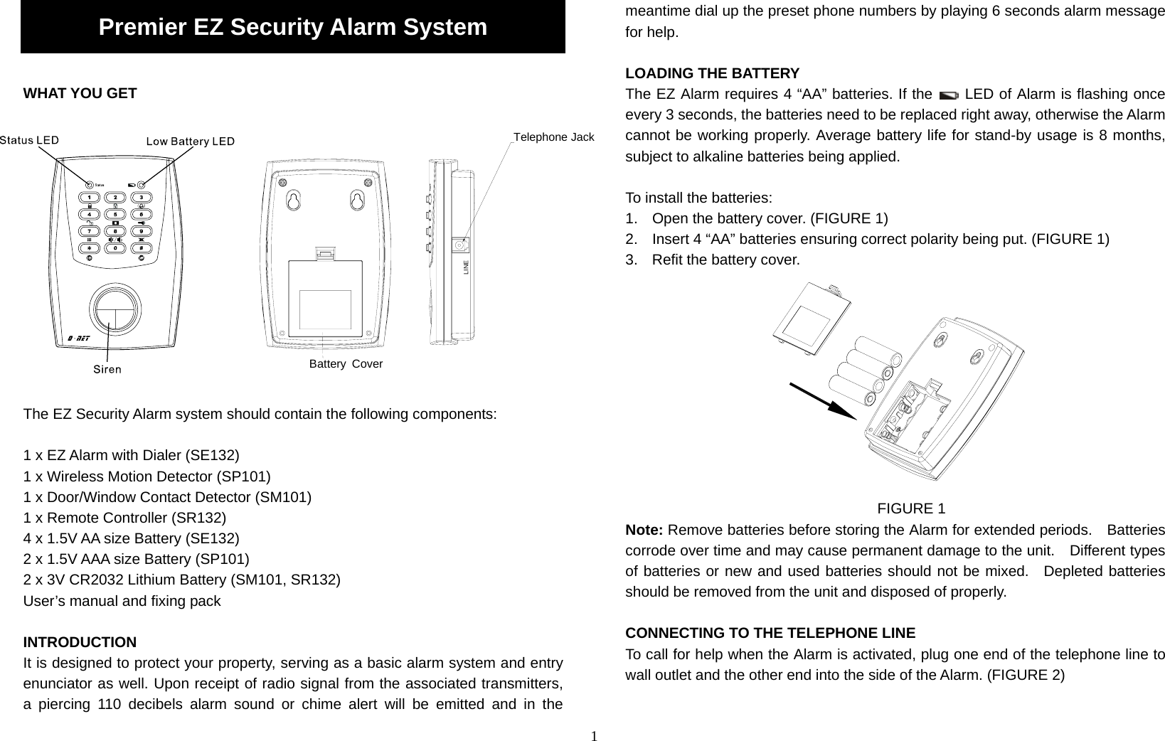
![2 FIGURE 2 CHOOSING A MOUNTING LOCATION When choosing a suitable location for the Alarm, the following points should be considered. 1. The Alarm should be located within a protected area with the System set, eg: an intruder cannot reach the Alarm without being detected by a detector. 2. The Alarm should be located in a position where it will be seen each day, but not visible from the door or windows. 3. Do not locate the Alarm closer than 1m to any large metallic object, eg: mirrors, radiators, fridges etc, as this may affect the radio range of the system. 4. Locate the Alarm in an easily accessible position between 1.5m and 2.0m above floor level. INSTALLING THE ALARM Mark the two fixing holes 50mm apart in a line on the wall. Drill two holes; fully insert the plastic wall plugs supplied and fit two 18mm screws into the wall plugs until almost fully home and hang the Alarm over these screws using the two keyhole slots in the top corners of the rear casing. (FIGURE 3) FIGURE 3 STARTING UP The Alarm is capable of memorizing up to 12 ID codes. For initial operation, the Status LED will flash once every 3 seconds, it means that the Alarm does not memorize any ID code or phone number. Without being programmed the phone number, the Alarm cannot make use of its dialer function, while failure in learning the ID code, the Alarm cannot be activated by the associated transmitters. It will stop flashing until the code learning and phone number have been programmed. Upon completion of batteries insertion, the Status LED will light up for one second and extinguish, confirming that the Alarm has initiated properly. The ex-factory mode is set for “disarm“ and 4-digit security code [ , , , ] has been set as the default security code. (Note: After removing or replacing the batteries, the Alarm security code would be automatically set back as default [ , , , ], while the preset ID codes will be still in existence.) SETTING THE 4-DIGIT SECURITY CODE Default setting: , , , For initial operation, press [ , , , ] 4-digit security code and then mode key, the Status LED and LED will keep illuminating. Press your new 4-digit security code and then mode key within 15 seconds. This 15-second allows users to enter new security code. As soon as the setting has been completed before 15-second is out, the Alarm will revert to disarm mode](https://usermanual.wiki/Everspring-Industry-Co/SR132-1/User-Guide-1053294-Page-2.png)