Everspring Industry Co SR801-2 U-NET SERIES User Manual
Everspring Industry Co Ltd U-NET SERIES Users Manual
Users Manual
1
Wirefree Remote Controller SR801-2
Installation and Operating Instructions
These instructions should be read in conjunction
with your System Installation and Operating
Manual and be retained for future reference
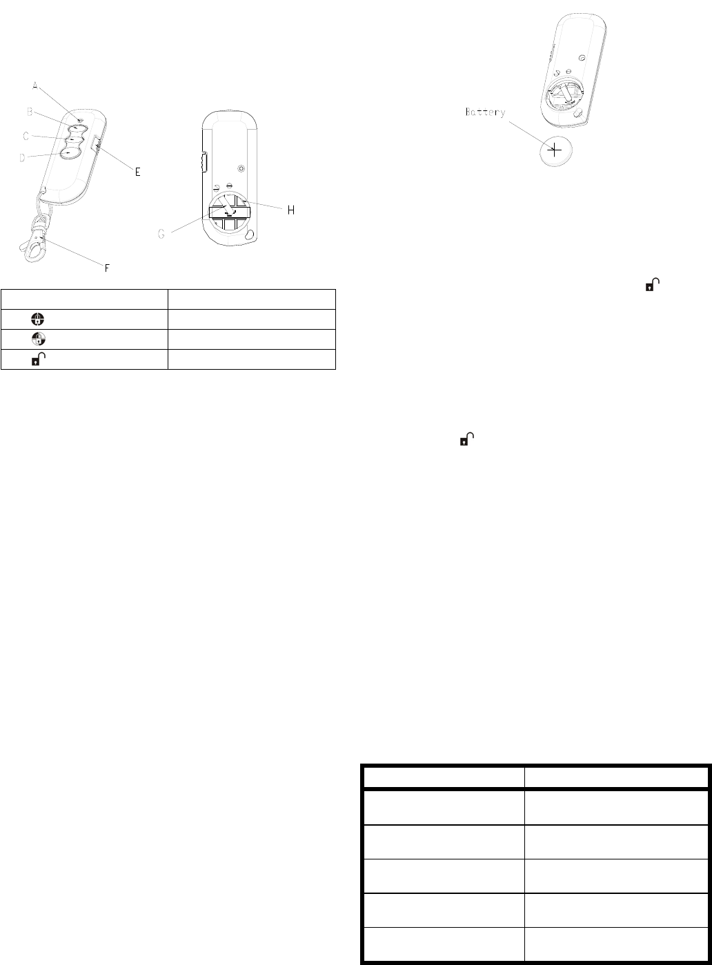
A LED indicator E Panic Switch
B Arm F Key Chain Ring
C Part-Arm G Negative Polarity
D Disarm H Positive Polarity
The Remote Controller is used to Arm, Part-Arm and
Disarm the system. It is compatible with a series of our
control panels, such as SC801 (2 zones), SC811 (8
zones), SC821 (12 zones) and SE801 (solar-powered
siren & strobe), operating at 868MHz or 923MHz only.
The Remote Controller also incorporates a Panic
switch. Activating the Panic switch will immediately
initiate a Full Alarm condition whether the system is
Armed or Disarmed, (unless the system is in Test
mode).
The Remote Controller adopts a CR2032 type Lithium
cell which under normal conditions will have typical life
in excess of 1 year. Under normal battery conditions
the LED on the Remote controller will only illuminate
when a button is pressed. However, under low
battery conditions the orange LED will illuminate every
time the button is pressed. When this occurs the
batteries should be replaced as soon as possible.
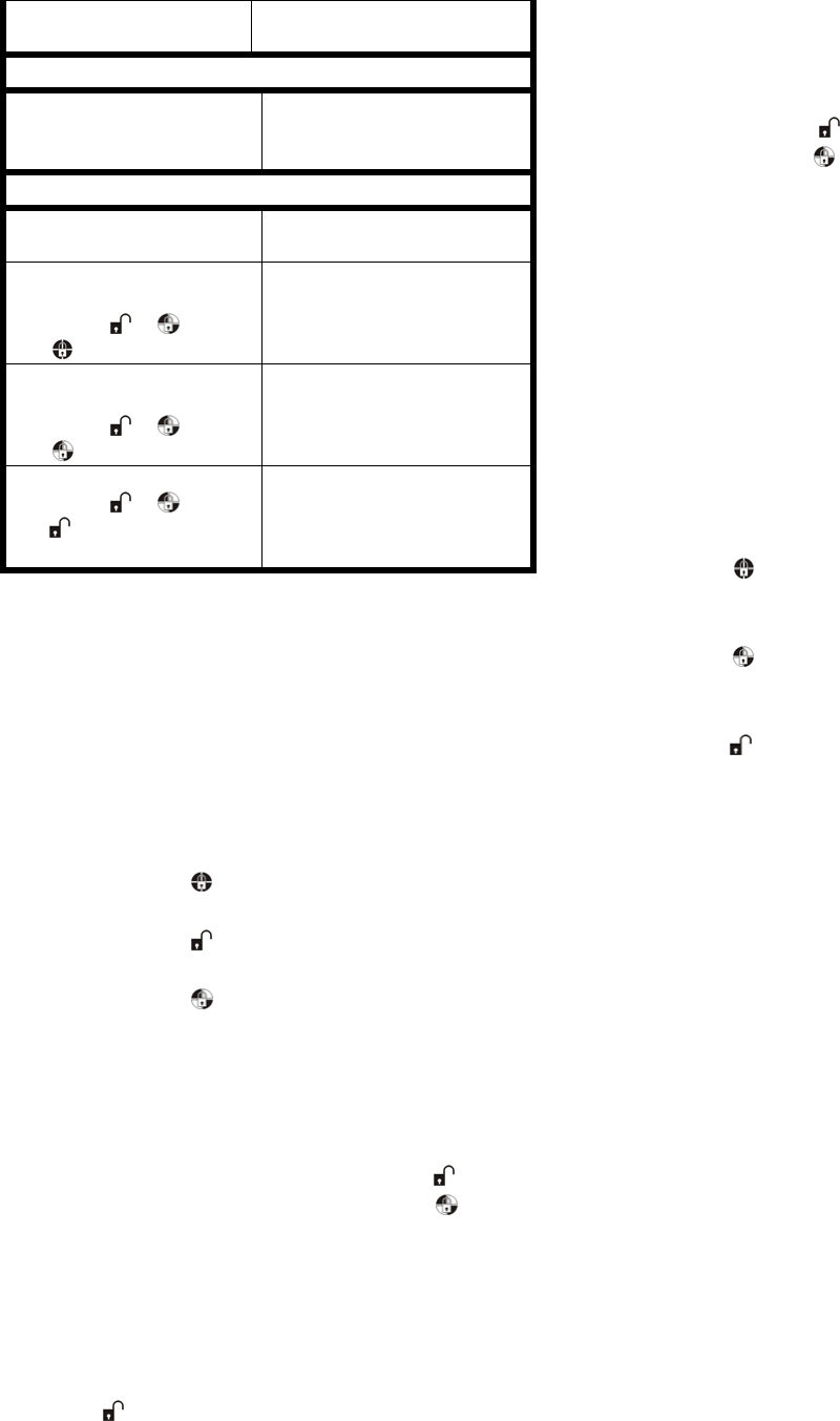
SETTING THE REMOTE CONTROLLER
1. Remove the rear cover with a coin.
2. Insert the battery ensuring that the +v terminal
faces upwards away from the PCB.
3. Replace the rear cover.
LEARNING THE ID CODE
In order to communicate with the Control Panel, the ID
code of the Remote Controller and Control Panel need
to be learnt with each other. By pressing the button
will emit the ID code to the Control Panel instantly,
subject to the Control Panel being set at the ID code
learning mode.
To emit the ID code to the control panel, proceed the
following steps in sequence:
1. Press the button for more than 3 seconds until
the green LED of the Remote Controller flashes. It
implies that the Remote Controller enters ID code
learning mode.
2. A 30-second countdown will start. If the ID code
has been learnt within 30 seconds by the control
panel successfully, the LED of the Remote
Controller will be on before exit the learning mode.
If failure, the LED of the Remote Controller will
flash three times rapidly before exit the learning
mode.
Note: The Remote Controller owns only one ID
code to be learnt by the control panel.
LED INDICATION
Function LED Indication
RF transmission Green LED illuminating for one
second
Failed RF transmission Red LED illuminating for one
second
Low battery Orange LED illuminating for
one second
Success in learning the ID
code
Green LED illuminating for 0.5
second
If the control panels have
been activated,
Green LED flashing for 3
seconds
2
the LED of Remote
Controller will be revealed
Connect to the Solar-powered siren & strobe (SE801)
System off Orange LED illuminating for 3
seconds -> Green LED
illuminating for 0.5 seconds
Connect to the SC801/SC811/SC821
Command in vain to the
control panel
Red LED flashing for 3
seconds
Enabling part-arm1 for
SP801 / SM801
1. Press
2.
1. Orange LED on steadily for
6 seconds -> flashing for
10 seconds
2. Green LED on for 1 second
Disabling part-arm1 for
SP801 / SM801
1. Press
2.
1. Orange LED on steadily for
6 seconds -> flashing for
10 seconds
2. Green LED on for 1 second
Omitting for SP801 / SM801
1. Press
2.
1. Orange LED on steadily for
6 seconds -> flashing for
10 seconds
2. Green LED on for 1 second
Note: Omit zone means a zone may be temporarily
omitted when the system is armed using the omit
feature. When the system is next disarmed any
zones set to omit will be cancelled.
Note: SP801 / SM801 refers to the Motion Sensor /
Door/Window Contact respectively.
OPERATING THE REMOTE CONTROLLER
1. Pressing the button will control the control
panel to enter the arm mode.
2. Pressing the button will control the control
panel to enter the disarm mode.
3. Pressing the button will control the control
panel to enter the part-arm 1.
4. By sliding the panic switch will activate the control
panel to initiate a full alarm condition.
5. When controlling the solar-powered siren & strobe
(SE801), proceed with the following steps:
a. System off: Press and hold the button
and use another finger to press the button,
the orange LED of the remote controller will
be illuminated for 3 seconds and turned
green for 0.5 seconds. It implies that the
remote controller emits a system off radio
signal to the solar-powered siren & strobe.
b. System on: Under system off mode, press the
button on the remote controller will control
the solar-powered siren & strobe to enter
system on mode.
SETTING THE PART-ARM & OMIT MODE
FOR THE MOTION SENSORS /
DOOR/WINDOW CONTACTS
When working with a SC series of our control panels,
I.E. SC801, SC811 & SC821, follow the steps below:
1. Press and hold the button and use another
finger to press the button. Do not release
these two buttons until the LED on the remote
controller has turned to orange. The orange LED
will illuminate for 6 seconds and be careful to
check out if the LED on both Motion Sensor
(SP801) / Door/Window Contacts (SM801) flashes
or not before 6 seconds is out. This is designed to
wake up the Motion Sensor (SP801) /
Door/Window Contacts (SM801). If the LED on
both sensors is flashing, it implies that the sensor
has been waked up. After 6 seconds has elapsed,
the orange LED on the Remote Controller will flash
for 10 seconds.
2. During this 10 seconds period,
- Press the button to emit enabled part-arm 1
command to the Motion Sensors (SP801) /
Door/Window Contacts (SM801).
- Press the button to emit disabled part-arm 1
command to the Motion Sensors (SP801) /
Door/Window Contacts (SM801).
- Press the button to emit omitted command to
the Motion Sensors (SP801) / Door/Window
Contacts (SM801).
Note: If failure to wake up or if there is an incorrect
control to the Motion Sensors (SP801) / Door/Window
Contacts (SM801), do not operate the remote controller
until the orange LED has flashed for 10 seconds.
TESTING THE REMOTE CONTROLLER
The operation of the Remote Controller should be
tested with the system in normal mode to ensure that
the new Remote Controller will successfully
communicate with the system and the Arm and Disarm
functions operate correctly. Also check by activating
the Panic switch on the Remote to initiate an alarm
condition.
Refer to your System Installation and Operating
Manual for further details on operating and testing the
system.
3
SPECIFICATIONS
Battery Type CR2032 3V/230mAhr
Operating Frequency 868MHz or 923MHz
*Specifications are subject to change without prior notice.
A501110742R01
Warning:
Do not dispose of electrical appliances as unsorted
municipal waste, use separate collection facilities.
Contact your local government for information
regarding the collection systems available.
If electrical appliances are disposed of in landfills or
dumps, hazardous substances can leak into the
groundwater and get into the food chain, damaging
your health and well-being.
When replacing old appliances with new once, the
retailer is legally obligated to take back your old
appliance for disposal at least for free of charge.
FEDERAL COMMUNICATIONS COMMISSION INTERFERENCE
STATEMENT
This equipment has been tested and found to comply
with the limits for a Class B digital device, pursuant to
Part 15 of the FCC Rules. These limits are designed to
provide reasonable protection against harmful
interference in a residential installation. This equipment
generates, uses and can radiate radio frequency
energy and, if not installed and used in accordance
with the instructions, may cause harmful interference to
radio communications. However, there is no guarantee
that interference will not occur in a particular
installation. If this equipment does cause harmful
interference to radio or television reception, which can
be determined by turning the equipment off and on, the
user is encouraged to try to correct the interference by
one or more of the following measures: – Reorient or
relocate the receiving antenna. – Increase the
separation between the equipment and receiver. –
Connect the equipment into an outlet on a circuit
different from that to which the receiver is connected. –
Consult the dealer or an experienced radio/TV
technician for help.
CAUTION:
Any changes or modifications not expressly approved
by the party responsible for compliance could void the
user's authority to operate the equipment.
This device complies with Part 15 of the FCC Rules.
Operation is subject to the following two conditions: (1)
This device may not cause harmful interference and (2)
This device must accept any interference received,
including interference that may cause undesired
operation.
Information for the OEMs and Integrators The following
statement must be included with all versions of this
document supplied to an OEM or integrator, but should
not be distributed to the end user. This device is
intended for OEM integrators only. Please See the full
Grant of Equipment document for other restrictions.
Label Information to the End User by the OEM or
Integrator The following regulatory and safety notices,
the final end product must be labeled with "Contains
FCC ID: FU5SR801-2 in a visible area.