Everspring Industry Co SR804 U-NET Series User Manual SR804 0 Keyfob Homesys 20170814
Everspring Industry Co Ltd U-NET Series SR804 0 Keyfob Homesys 20170814
User manual
1
SR804 Wireless Keyfob
Installation Instructions
General Introduction
The SR804 Wireless Keyfob is used to Arm, Partial Arm and Disarm the system.
The Keyfob also incorporates a Panic switch that will immediately initiate a Full
Alarm condition when the system is Armed or Disarmed. Its great compatibility with
our U-Net family security products makes it suitable for smart home cloud based
platforms such as Homesys
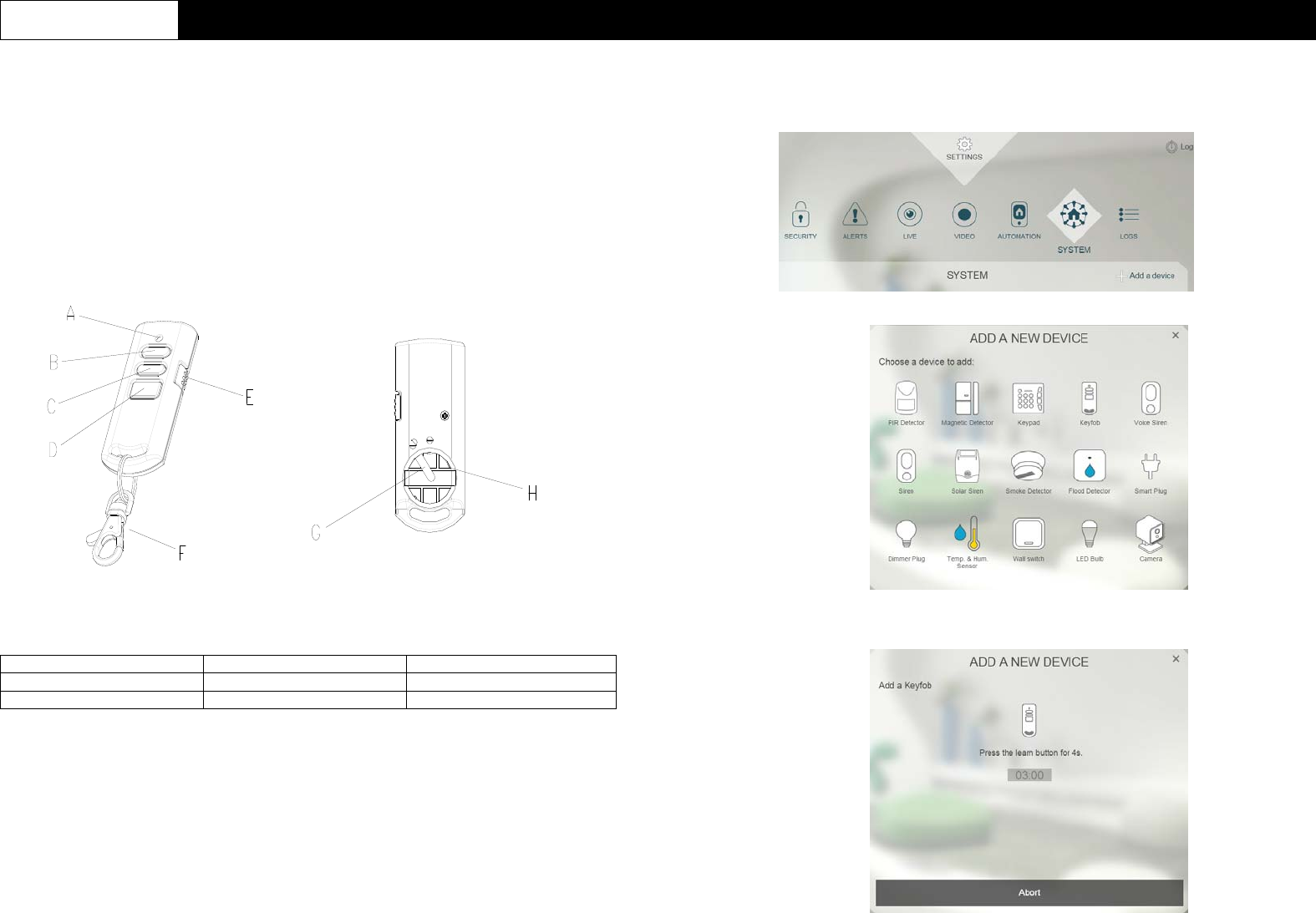
Product Overview
A
LED indicator B Arm C Partial Arm
D Disarm E Panic Switch F Key Chain Ring
G Ne
g
ative Polarit
y
H Positive Polarit
y
Binding with Homesys
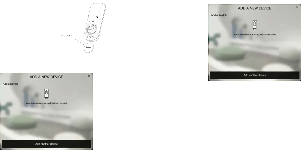
1. Remove the battery cover behind the keyfob.
2. Prepare the CR2032 coin cell battery by removing any plastic wrapping on the
battery. Do not insert the batteries yet into the unit.
3. Log into the Homesys account from a web browser.
4. Select “System”, then “Add a New Device”.
5. Select “Keyfob”.
6. The following screen will appear. This means the gateway is entering binding
mode.
2
7. Insert the battery ensuring that the +v terminal faces upwards away from the
PCB and replace the battery cover.
8. The screen below will appear in 10 seconds if the process is successful.
9. Time-out will occur if the binding process was unsuccessful. Please refer to the
“Manual binding” section.
Manual Binding
1. With the battery inserted, repeat steps 3 to 6 of the Binding with Homesys
section.
2. Press and hold the Disarm button for more than 3 seconds until the LED flashes
moderately (on for 2 second; off for 2 second). This implies keyfob has now
entered the binding mode and is waiting to receive binding signals from the
gateway.
3. Within 5 secs, the LED indicator then stop flashing and turn off, indicating the
learning procedure is completed. The screen below will appear indicating the
process is successful.
4. If after 30 seconds LED flashes rapidly for 3 times, it means the keyfob fails the
binding process
Operation & Testing
Operating the Keyfob
There are 5 operating modes provided by the keyfob.
1. ARM : Press and release the ARM button.
2. DISARM : Press and release
3. PARTIAL ARM 1: Press and release the Partial Arm button once
4. PANIC: Slide the Panic Switch and hold for at least 3 secs before releasing.
Note: The LED on the keyfob will turn green after button press is released. This
implies the keyfob receives a confirmation signal from the Gateway. Instead if the
LED turns red, this means the keyfob did not receive the reply from gateway
Testing the Keyfob
1. Press the Arm button to see if there is an entry in the LOGS page of your
Homesys account.
2. Press the Partial Arm button to see if there is an entry in the LOGS page of your
Homesys account.
3. Press the Disarm button to see if there is an entry in the LOGS page of your
Homesys account.
4. Slide the Panic Switch and hold for at least 3 secs before releasing. See if there
is an entry in the LOGS page of your Homesys account.
Note: Press the Disarm button to deactivate a triggered alarm and siren sound.
3
Maintenance
Low Battery: When the battery becomes low, the LED will turn orange after
each press to indicate low battery condition to the user. Replace the battery
when this occurs.
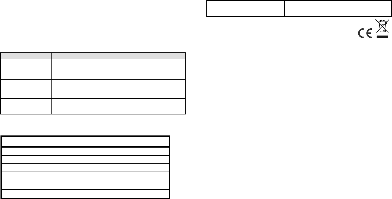
Troubleshooting
The troubleshooting table lists some possible causes and solutions. Please contact
your original retailer or nearest service center if the below solutions cannot solve
your problem.
Symptom Cause of Failure Recommendation
LED cannot be
displayed 1. Run out of battery
power.
2. Check if reverse battery
p
olarit
y
.
1. Replace a new battery.
2. Refit the battery with correct
polarity.
LED turns red after
pressing the button 1. Keyfob is out of range of
the gateway. 1. Move closer to the gateway
2. Hold the keyfob higher and
p
ress a
g
ain.
LED blinks green
slowly for 30secs after
power on.
1. Keyfob has not bind
with Gateway 1. Remove the battery and
perform binding with Homesys
procedure.
LED Table
The table below summarizes the LED indication of the keyfob.
Function LED Indication
RF transmission Green LED illuminating for 1 second
Failed RF transmission Red LED illuminating for 1 second
Low battery Orange LED illuminating for 1 second
Binding in process LED flashing with an interval of 2 seconds
Binding successful Green LED illuminating for 0.5 seconds
Binding timeout Green LED flash 3 times.
Reset to Factory Settings
1. Remove the battery from the keyfob.
2. Using two fingers, press and hold both the Arm and Disarm simultaneously
while inserting the battery.
3. Keep pressing both buttons for more than 5 secs until the detector’s LED blinks
red, this implies the device is reset back to factory mode.
Note: After power on, the Keyfob will automatically enter “Auto-binding” mode
to bind with a gateway. The auto-binding process lasts for 30 seconds
indicated by the LED blinking slowly.
Specifications
Batter
y
CR2032 3V/230mAh
O
p
eratin
g
Fre
q
uenc
y
868MHz
(
EU
)
/ 923MHz
(
America
)
Operatin
g
Temperature -10°C to 40°C
** Specifications are subject to change without notice.
WARNING:
Do not dispose of electrical appliances as unsorted municipal waste, use separate
collection facilities instead. Please contact your local government for information
regarding the collection systems available.
If electrical appliances are disposed of in landfills or dumps, hazardous substances
can leak into the groundwater and get into the food chain, damaging your health
and well-being.
When replacing old appliances with new once, the retailer is legally obligated to
take back your old appliance for disposal at least for free of charge.
Federal Communication Commission Interference Statement
This equipment has been tested and found to comply with the limits for a Class B
digital device, pursuant to Part 15 of the FCC Rules. These limits are designed to
provide reasonable protection against harmful interference in a residential
installation. This equipment generates, uses and can
radiate radio frequency energy and, if not installed and used in accordance with the
instructions, may cause harmful interference to radio communications. However,
there is no guarantee that interference will not occur in a particular installation. If this
equipment does cause harmful interference to radio or television reception, which
can be determined by turning the equipment off and on, the user is encouraged to
try to correct the interference by one of the following measures:
- Reorient or relocate the receiving antenna.
- Increase the separation between the equipment and receiver.
- Connect the equipment into an outlet on a circuit different from that to which the
receiver is connected.
- Consult the dealer or an experienced radio/TV technician for help.
This device complies with Part 15 of the FCC Rules. Operation is subject to the
following two conditions: (1) This device may not cause harmful interference, and (2)
this device must accept any interference received, including interference that may
cause undesired operation.
FCC Caution: Any changes or modifications not expressly approved by the party
responsible for compliance could void the user's authority to operate this
equipment.
This transmitter must not be co-located or operating in conjunction with any other
antenna or transmitter.

4
www.everspring.com
3F., No. 50, Sec 1, Zhonghua Rd., Tucheng Dist.,
New Taipei City 23666, R.O.C
A501112387R01