Everspring Industry Co ST113 Pool Alarm User Manual POOL ALARM
Everspring Industry Co Ltd Pool Alarm POOL ALARM
UserManual.wiki
>
Everspring Industry Co
>
ST113 User Manual
User manual
Navigation menu
Upload a User Manual
Namespaces
Wiki Guide
HTML
PDF
Info
Views
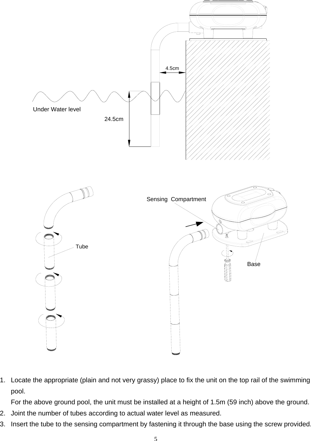
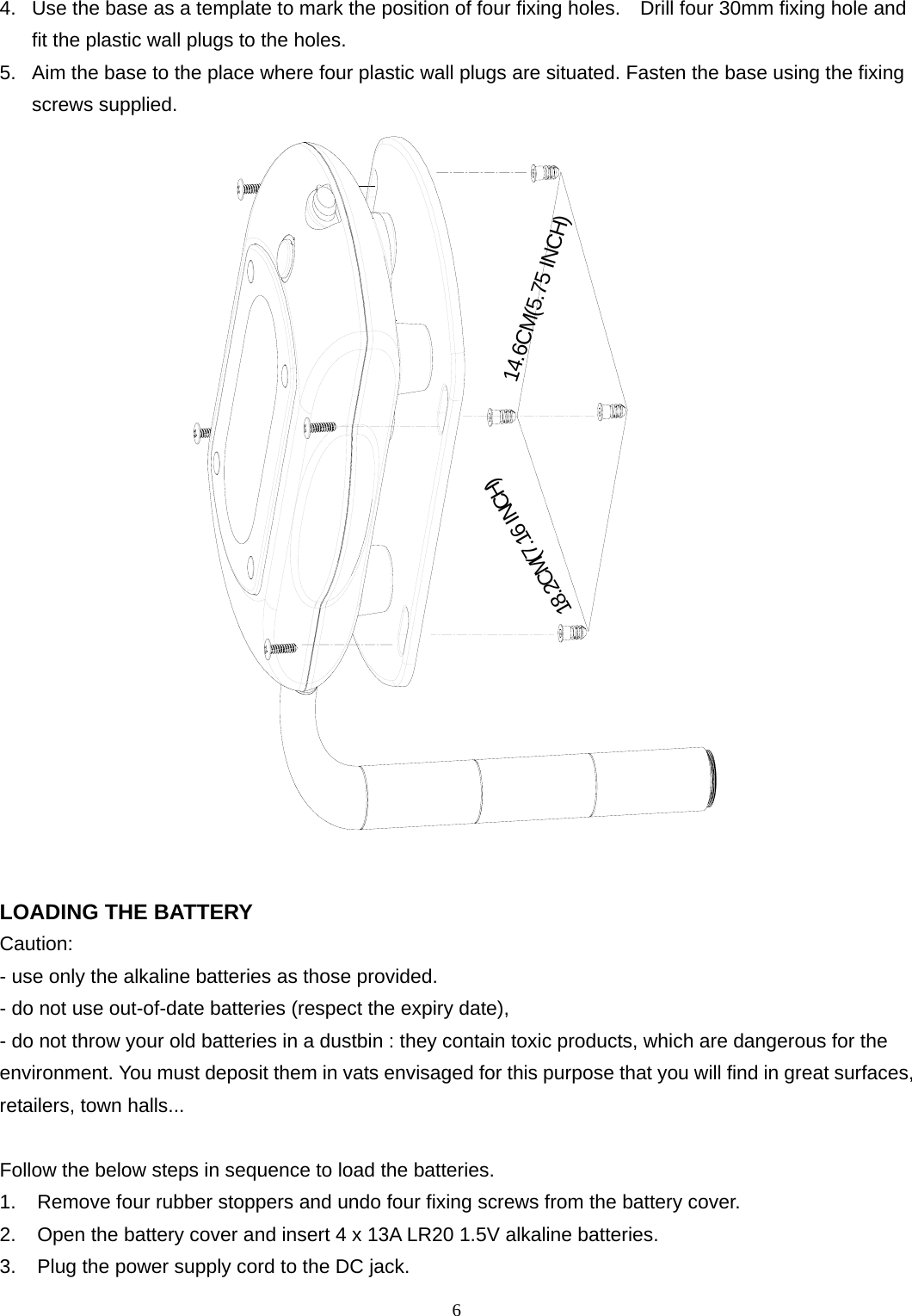
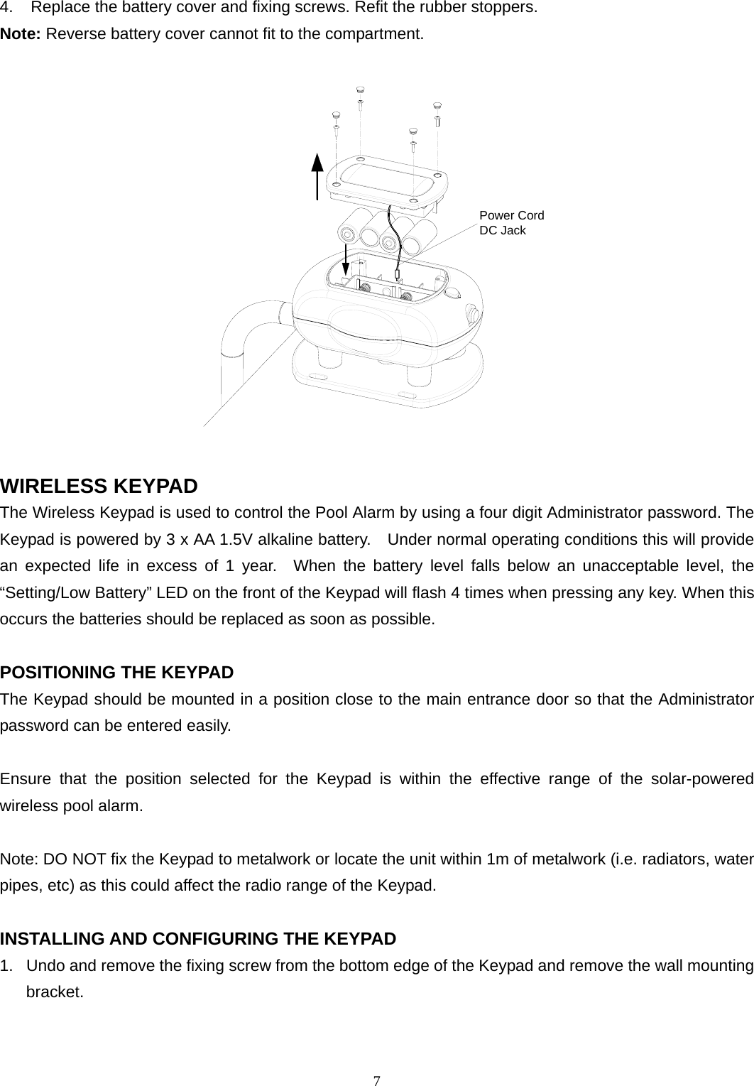
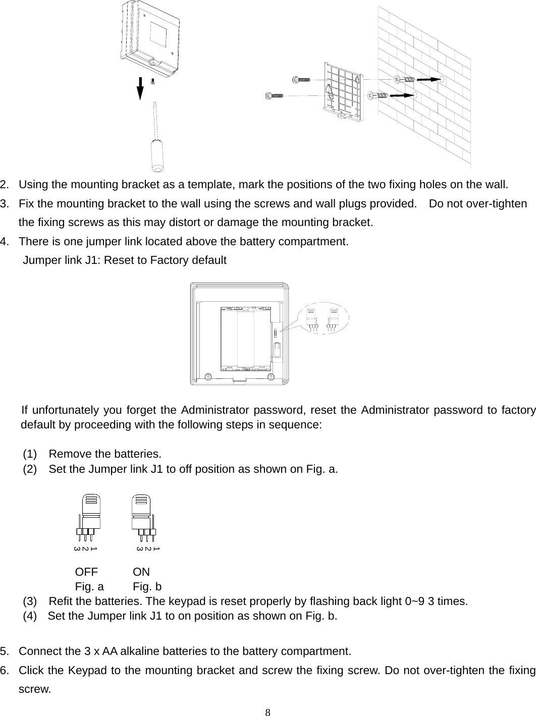
User Manual
Discussion / Help
Navigation