Everspring Industry Co TSC06 Wireless IP gateway User Manual
Everspring Industry Co Ltd Wireless IP gateway
UserManual.wiki
>
Everspring Industry Co
>
TSC06 User Manual
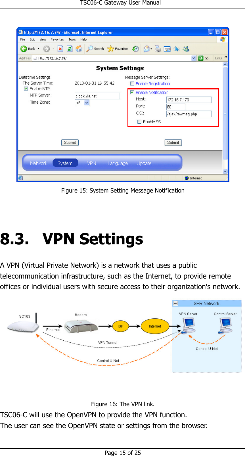
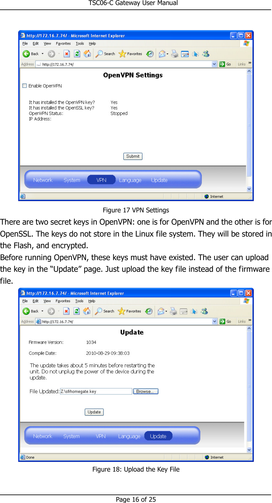
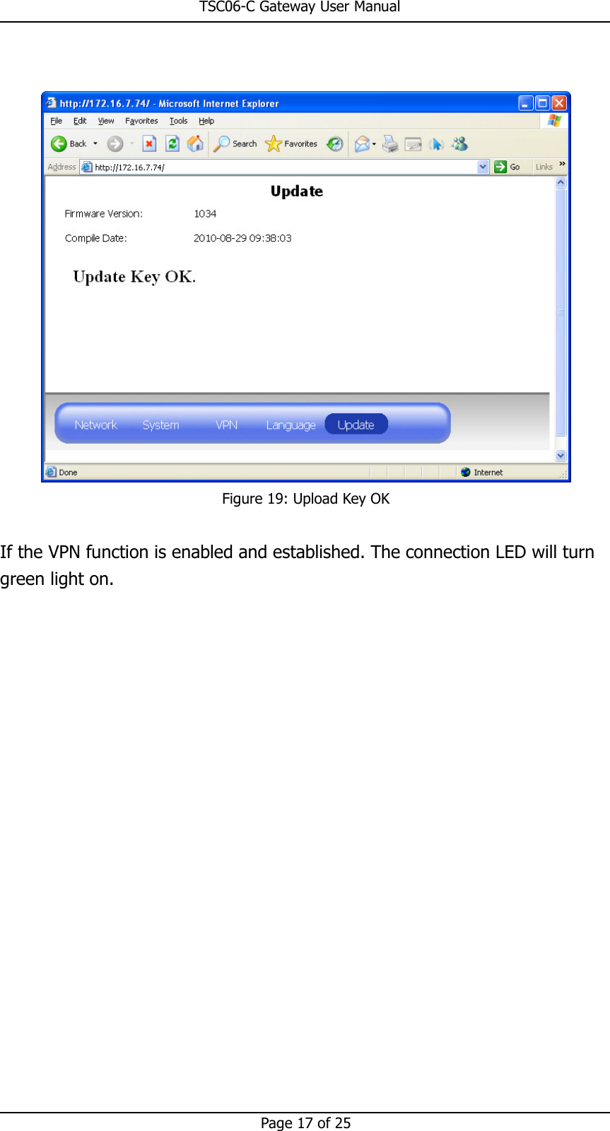
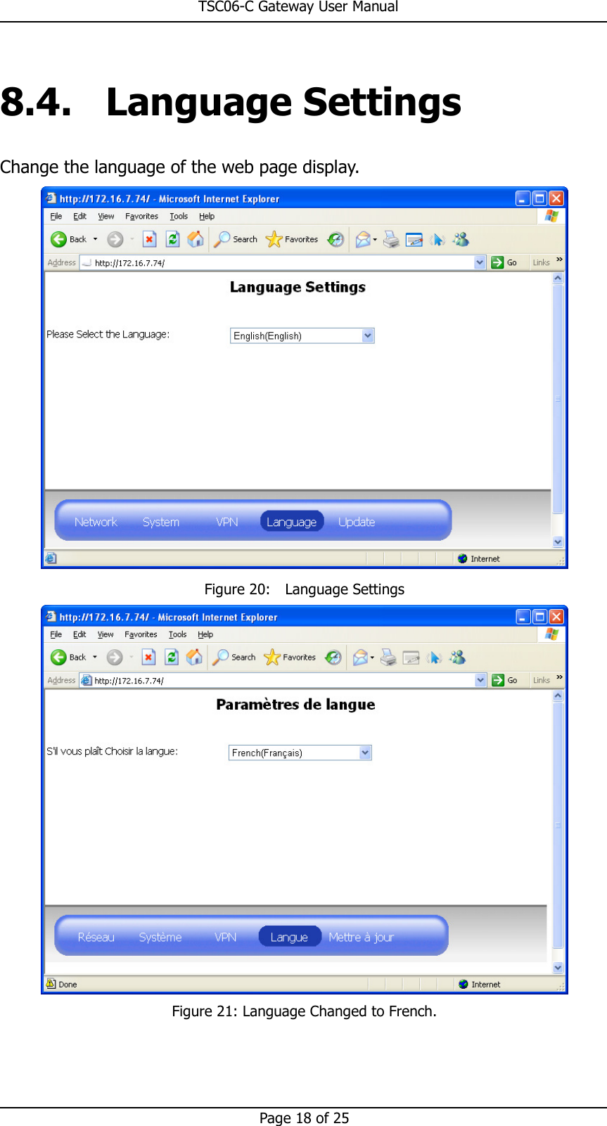
User Manual
Navigation menu
Upload a User Manual
Namespaces
Wiki Guide
HTML
PDF
Info
Views
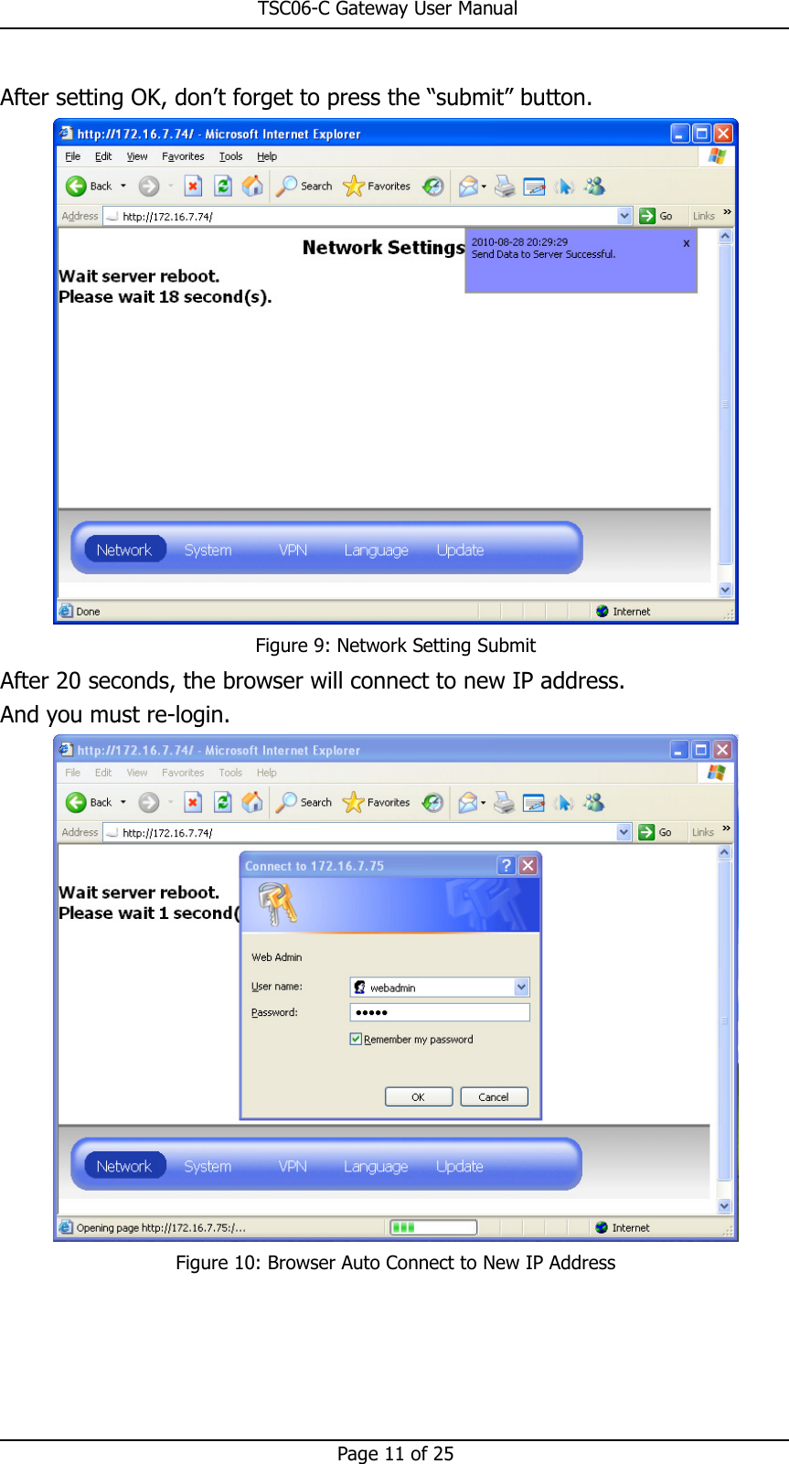
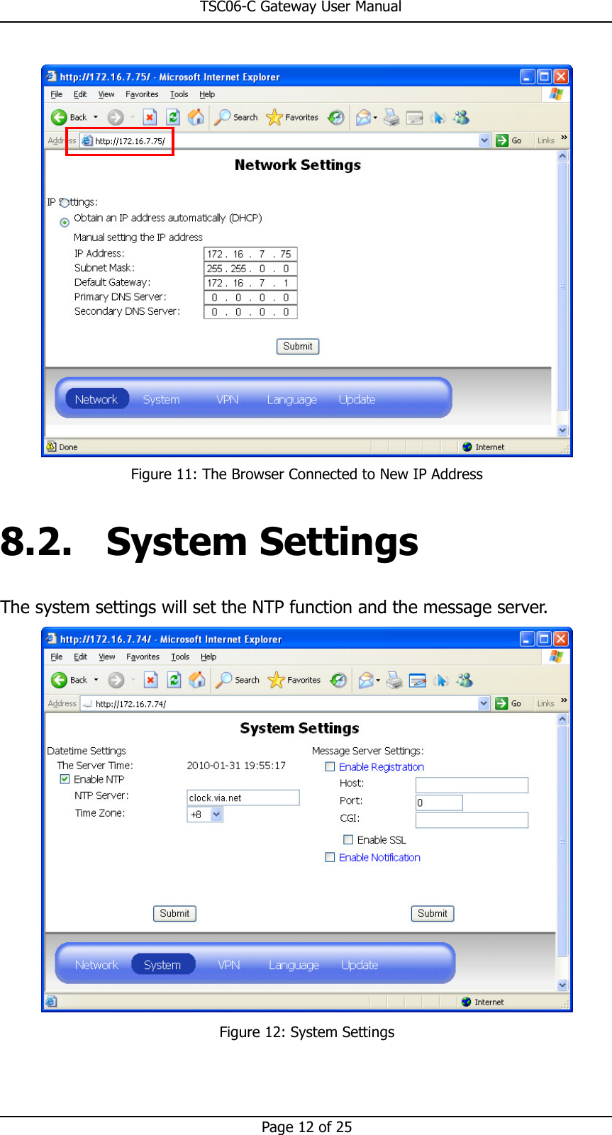
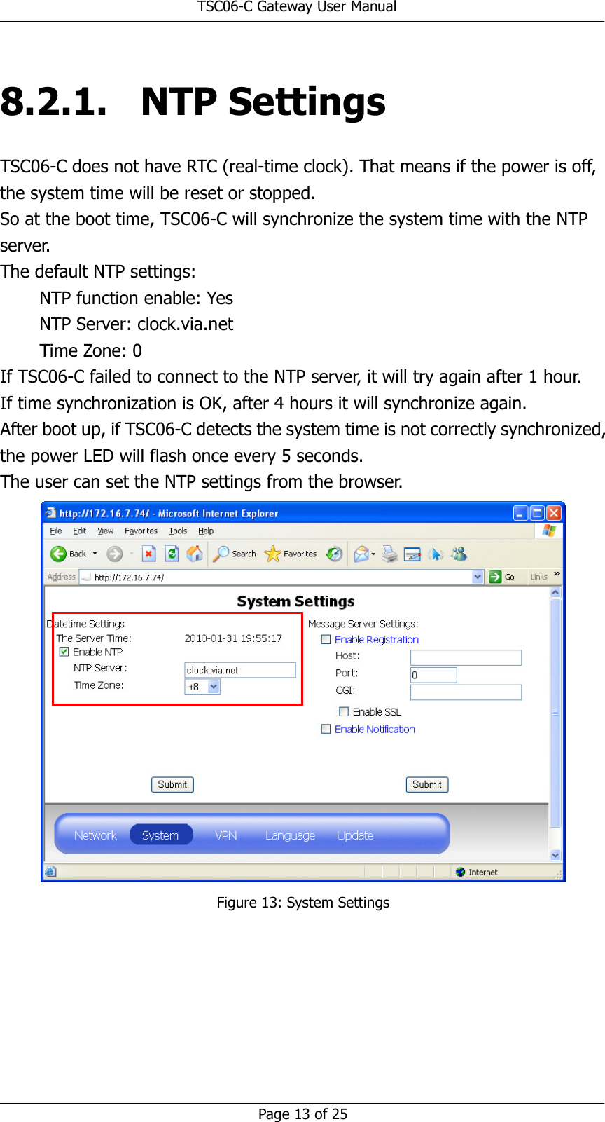
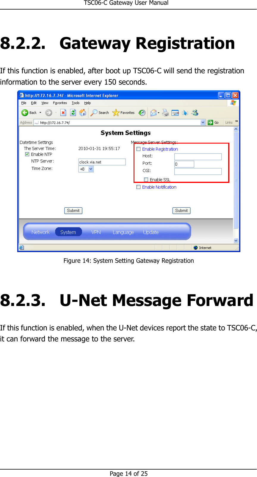
User Manual
Discussion / Help
Navigation