Everspring Industry Co VC401 2.4GHz DETACHABLE SOLAR CAMERA WIRELESS CCTV User Manual VC401
Everspring Industry Co Ltd 2.4GHz DETACHABLE SOLAR CAMERA WIRELESS CCTV VC401
USERS MANUAL
1
VC401 SOLAR PIR CAMERA SYSTEM
Installation and Operating Manual
What you get
There are two kind of compositions for you to choose from.
One is a Solar PIR Camera System and the other is a single
PIR Camera, both of which compositions are listed hereunder:
Solar PIR Camera System (VC401)
● 1 x PIR Camera (VC401)
● 1 x Solar Panel (EL401)
● 1 x 10m Cable
● 1 x 6V 1.2Ah Rechargeable Battery
● 1 x 9V Alkaline Battery
Single PIR Camera (VC401)
● 1 x PIR Camera
● 1 x AC Adapter 120V 60Hz /7.5VDC 300mA or
1 x AC Adapter 230V 50Hz /7.5VDC 300mA
● 1 x 6V 1.2Ah Rechargeable Battery
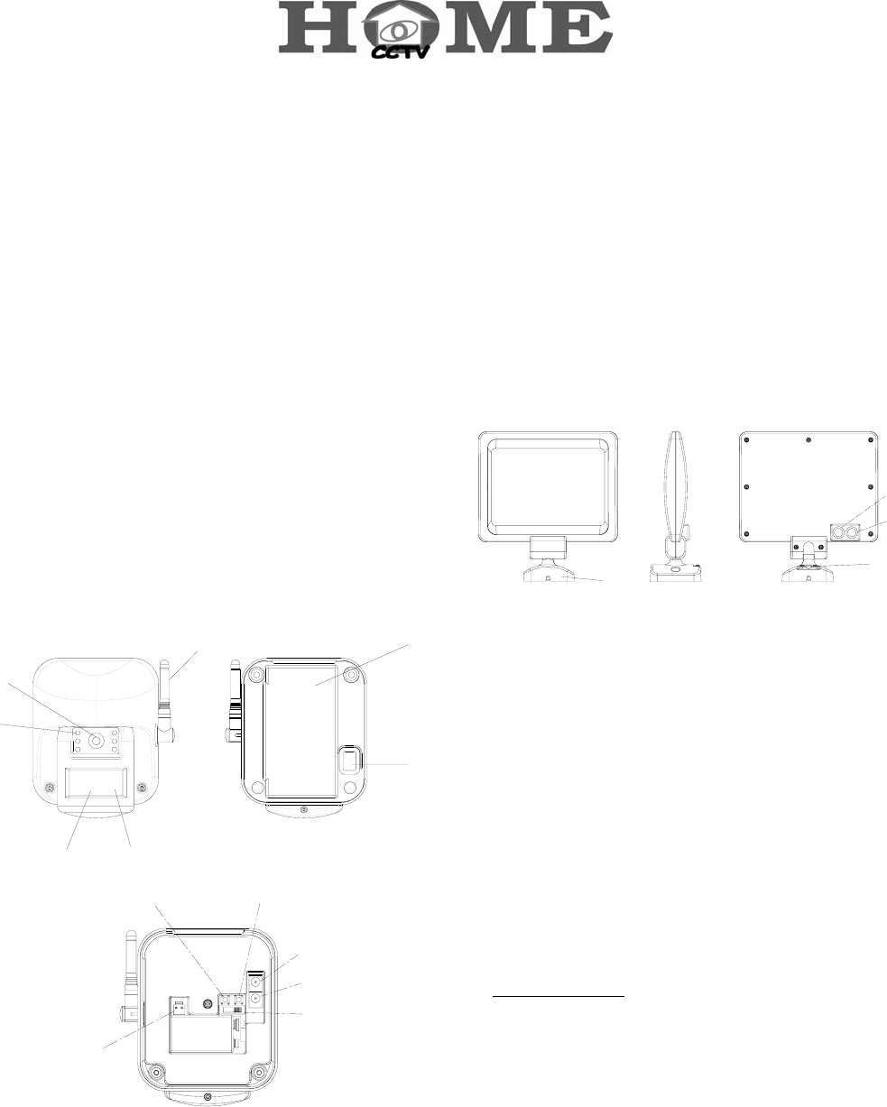
Product Layout
PIR Camera (VC401)
1
2
3
4
6
7
5
8
910
11
12
13
1. Lens
2. Infrared LEDs
3. PIR
4. Antenna
5. LED
6. Backplate
7. Rubber gasket
8. Battery jack
9. Learn button
10. Reset button
11. Solar jack
12. DC jack
13. Channel switch
Solar Panel (EL401)
1
2
3
4
1. Base
2. Solar Power Out
3. Solar Power In
4. Strain Relief
Introduction
The Solar PIR Camera System is designed to economically
provide safety, security, convenience to your home and
business. Its solar panel collects daylight and maintains a
charge to the battery of the camera during daylight hours. A
negligible amount of energy is released by the rechargeable
battery to operate the camera during nighttime.
Caution
Pay attention to the following before you install:
1. Sufficient daylight: Solar panel requires constant charge
during daylight hours. Please mount the solar panel at the
location that can receive sufficient daylight exposure.
To provide the optimum amount of sunlight to the Solar
Panel, you should ideally mount the Solar Panel on a
south facing wall. However, an easterly or westerly
position will suffice.
Although the Solar Panel is designed to work on any
aspect wall, you should refrain from siting the unit on a
north facing wall where possible.
2
Shadows cast by neighbouring walls, trees and roof
overhangs should also be avoided. In practice, the Solar
Panel should be positioned a minimum of twice the width
of the eaves overhang, below the eaves where is
reachable to sun exposure. Remember that in winter the
sun is lower in the sky and you should avoid winter
shadows where possible.
2. Detecting sensitivity: A passive infrared sensor operates by
detecting the objective movement and heat. When the
temperature of the moving object and its surrounding area
are close in value, it may reduce PIR’s sensitivity. The
motion detector’s infrared beams radiate outward like the
slat of a wooden fence. Prior to mounting, keep in mind
that the motion sensor is more sensitive to the motion that
crosses these “slats”, and less sensitive to the motion that
moves directly towards the sensor.
3. Mounting height: For best results, mount the camera 2m
above the ground. Select an appropriate location where
the camera can clearly be seen and detect for best viewing
effect.
4. Rechargeable battery
A high capacity 6V 1.2Ah sealed lead acid rechargeable
battery ensures that the Solar Panel is self maintainable
during darkness and long winter periods.
5. Initial power-up battery
An Alkaline 9V PP3 battery is supplied in the PIR Camera
to provide the initial power to the system.
6. Infrared LEDs for improved night vision
When PIR Camera is activated during nighttime, 6 infrared
LEDs adjacent to the lens is of great help to enhance
nighttime visibility.
7. Reset button
When PIR Camera is not working properly, press the reset
button for recovery.
Installation
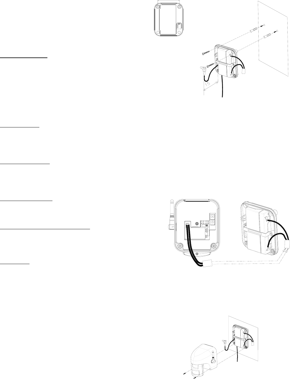
Step 1: Install the PIR camera
1. Use the fixing template provided to mark the position of the
two fixing holes. Drill two holes with 25mm in depth and
5mm in width by inserting the plastic wall plugs supplied.
2. Lead either the jack of solar connecting wire or the jack of
DC power cord through the rubber gasket on the backplate,
leaving 15cm length of wire inside the backplate. (FIGURE
1)
74mm
cm
FIGURE 1
Note: If only a PIR Camera (VC401) is used, adopt the DC
power cord for connection. If a whole system (VC401) is
used, adopt the solar connecting wire for connection.
3. Screw the backplate to the wall using the fixing screws
provided.
4. Adjust the channel switch, enabling its channel to be the
same as that of the Receiver, such as Universal Receiver
(VR111) or Wireless USB Receiver (VR131).
5. Connect the connector of rechargeable battery wire to the
wire of battery jack. (FIGURE 2)
FIGURE 2
6. Plug either the jack of solar connecting wire or the jack of
DC power cord to the camera’s jack socket.
7. Refit the camera to the backplate using two fixing screws
provided. (FIGURE 3)
FIGURE 3
8. The PIR Camera can be swiveled downward to 50° and
3
160° horizontally.
9. Adjust the PIR Camera angle according to your need.
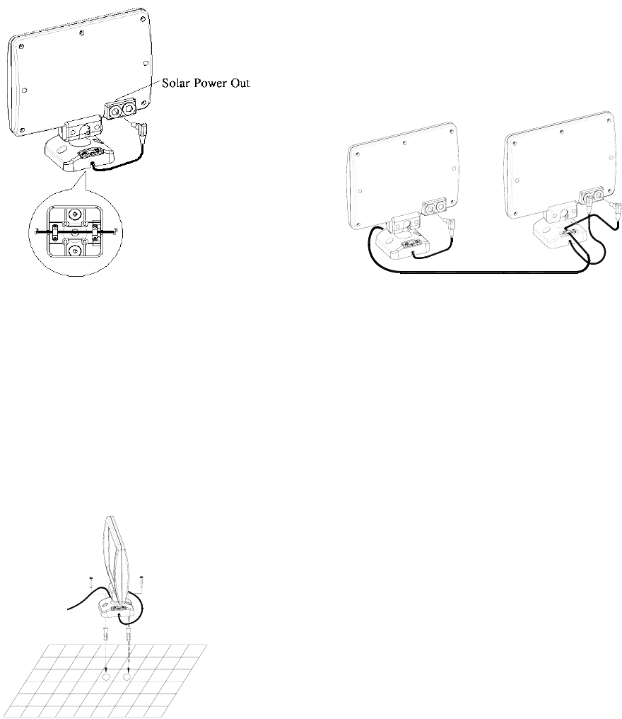
Step 2: Install the Solar Panel
1. Using the fixing template to mark the position of two fixing
holes. Drill two holes with 25mm in depth and 5mm in
width by inserting the plastic wall plugs supplied.
2. Loosen the screws from the strain relief located on the
base of solar panel. (FIGURE 4)
FIGURE 4
3. Route the solar connecting wire though two strain relief
and fix them in place with screws respectively, leaving
20cm length of connecting wire for further connection.
4. Plug one end of the jacks with 20cm length of connecting
wire to the ‘solar power out’ of rear side of the solar panel.
(FIGURE 4)
5. Plug the other end of the jack to the Camera’s solar jack
socket.
6. Fix the base of solar panel to the plastic wall plugs using
two screws provided. (FIGURE 5)
FIGURE 5
Step 3: Expand the Solar Panel (option)
1. Using the fixing template to mark the position of two fixing
holes. Drill two holes with 25mm in depth and 5mm in
width by inserting the plastic wall plugs supplied.
2. Loosen the screws from the strain relief located on the
base of solar panel. (FIGURE 4)
3. Route the solar connecting wire though two strain relief
and fix them in place with screws respectively, leaving
20cm length of connecting wire for further connection.
4. Plug one end of the jacks with 20cm length of connecting
wire to the ‘solar power out’ of rear side of the solar panel.
5. Plug the other end of the jack to the ‘solar power in’ of the
rear side of the first solar panel. Fix its solar connecting
wire to the strain relief of the base of solar panel, using the
screws provided. (FIGURE 6)
2
nd. 1
st.
FIGURE 6
6. Fix the base of solar panel to the plastic wall plugs using
two screws provided.
Operating Instruction
1. When connecting to a 6V/1.2Ah rechargeable battery, the
PIR Camera will enter warm-up period for 1 minute and its
LED will illuminate steadily. During warm-up period, the
PIR Camera will not transmit any radio signal. Once the
PIR Camera is triggered, the camera images can be
viewed from the video devices for 1 minute, then turned
off.
2. When connecting to a 7.5V/300mA adapter (optional), the
PIR Camera will warm up for 1 minute and its LED will
illuminate steadily. During warm-up period, the PIR
Camera will keep emitting radio signal. Once the PIR
Camera is activated, the camera images can be viewed
from the video devices for 1 minute then turned off.
Regardless of no activation, 24h surveillance can be made
via turning on the video devices.
3. Turn on TV or monitor and walk through the detection
coverage of PIR Camera, the camera images can be
viewed instantly.

4
4. When the image on TV is not clear, it means that
somebody may use the same channel as yours in your
neighborhood. For fast resolution, adjust the PIR Camera
and receiver to another channel.
Troubleshooting
Status Possible Cause Remedy
LED does not
light up
a. Reverse polarity
b. Run out of battery
a. Follow the
polarity shown
inside the battery
compartment for
loading the
batteries
b. Insert a 9V
battery and
have it charged
to the 6V
rechargeable
battery
Ambiguous
image under
observation
a. Channel has been
interfered
b. Receiving/transmission
distance too far or radio
signal has been blocked
a. Check that the
channel
switches on the
PIR Camera
and Receiver
are set to the
same number
b. Reposition the
PIR Camera or
Receiver
5
Specifications
VC401 Solar PIR Camera System
Camera Type Color Camera Angle Left & Right ±80°, Down 50°
Picture Type CMOS Microphone Build in
TV System PAL/NTSC Transmitting Frequency 2400~2483MHz (for 4 channels)
Sensitivity 3Lux f1.2
Resolution (TV lines) 250
Battery 1 x 9V back up battery, 1x 6V
rechargeable battery
Lens Angle 56° Diagonal Power Supply Source Solar Panel (110*160mm)
Lens 6.0mm F1.8 Channel Switch 4 positions for 1~4 selection
AC Adapter (option) AC120V 60Hz / 7.5V DC 300mA
AC230V 50Hz / 7.5V DC 300mA
PIR Detect ion
Distance/Angle 8M/80° (under 28°C)
© 2006 Everspring Industry Co., All Rights Reserved. A501110214R
Federal Communication Commission Interference Statement
This equipment has been tested and found to comply with the limits for a Class B digital device, pursuant to Part 15 o
f
the FCC Rules. These limits are designed to provide reasonable protection against harmful interference in a
residential installation. This equipment generates, uses and can radiate radio frequency energy and, if not installed
and used in accordance with the instructions, may cause harmful interference to radio communications. However,
there is no guarantee that interference will not occur in a particular installation. If this equipment does cause harmful
interference to radio or television reception, which can be determined by turning the equipment off and on, the user is
encouraged to try to correct the interference by one of the following measures:
- Reorient or relocate the receiving antenna.
- Increase the separation between the equipment and receiver.
- Connect the equipment into an outlet on a circuit different from that to which the receiver is connected.
- Consult the dealer or an experienced radio/TV technician for help.
This device complies with Part 15 of the FCC Rules. Operation is subject to the following two conditions: (1) This
device may not cause harmful interference, and (2) this device must accept any interference received, including
interference that may cause undesired operation.
FCC Caution: Any changes or modifications not expressly approved by the party responsible for compliance could void
the user's authority to operate this equipment.
IMPORTANT NOTE:
Do not dispose of electrical appliances as unsorted municipal waste, use separate collection facilities.
Contact your local government for information regarding the collection systems available.
If electrical appliances are disposed of in landfills or dumps, hazardous substances can leak into the groundwater and
get into the food chain, damaging your health and well-being.
When replacing old appliances with new once, the retailer is legally obligated to take back your old appliance fo
r
disposal at least for free of charge.