Everspring Industry Co VC451 SOLAR-POWERED PIR CAMERA KIT User Manual U
Everspring Industry Co Ltd SOLAR-POWERED PIR CAMERA KIT U
User Manual
1
VC451 SOLAR-POWERED PIR CAMERA KIT
Installation and Operating Manual
What you get
The components included in the C451Solar-powered PIR
Camera Kit:
● 1 x PIR Camera with Solar Panel (VC451)
● 1 x Remote Control (SR103)
● 1 x 6V 1.2A Rechargeable Battery
● 1 x 9V Alkaline Battery
● 1 x 3V CR2032 Lithium Battery
● 1 x Waterproof Rubber Plug
● Fixing Pack and Operating Instruction
Product Layout
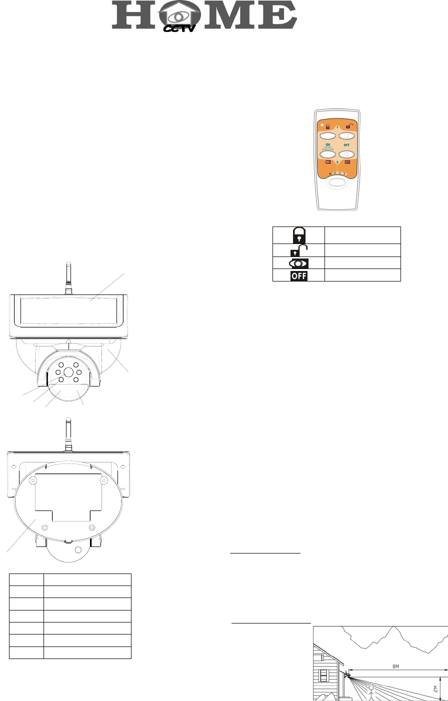
PIR Camera with Solar Panel (VC451)
1
2
34
5
6
7
1 Lens
2 Infrared LED
3 PIR Motion Sensor
4 Status LED
5 Solar Panel
6 Front Cover
7 Back plate
Remote Control (SR103)
Arm
Disarm
Camera on
Camera off
Introduction
The 2.4GHz Solar-powered Color PIR Camera Kit is a truly
wireless camera, receiving all of its required energy from the
sun. With no wires to run, this camera installs easily, providing
security and convenience in a simple, economical manner. Its
solar panel collects daylight and maintains a charge to the
battery of the camera during daylight hours. A negligible amount
of energy is released by the rechargeable battery to operate the
camera during nighttime.
When the camera's PIR motion sensor detects motion, images
and voices are transmitted. Upon receiving these signals, the
optional wireless receiver (VR111) will activate the VCR/DVR to
start recording, so you'll know who visits or breaks in your
property while you are away.
Caution
Pay attention to the following before you install:
1. Sufficient daylight: Solar panel requires constant charge
during daylight hours. Please mount the camera at the location
that can receive sufficient daylight exposure.
Mount the PIR Camera at 2m height above the ground.
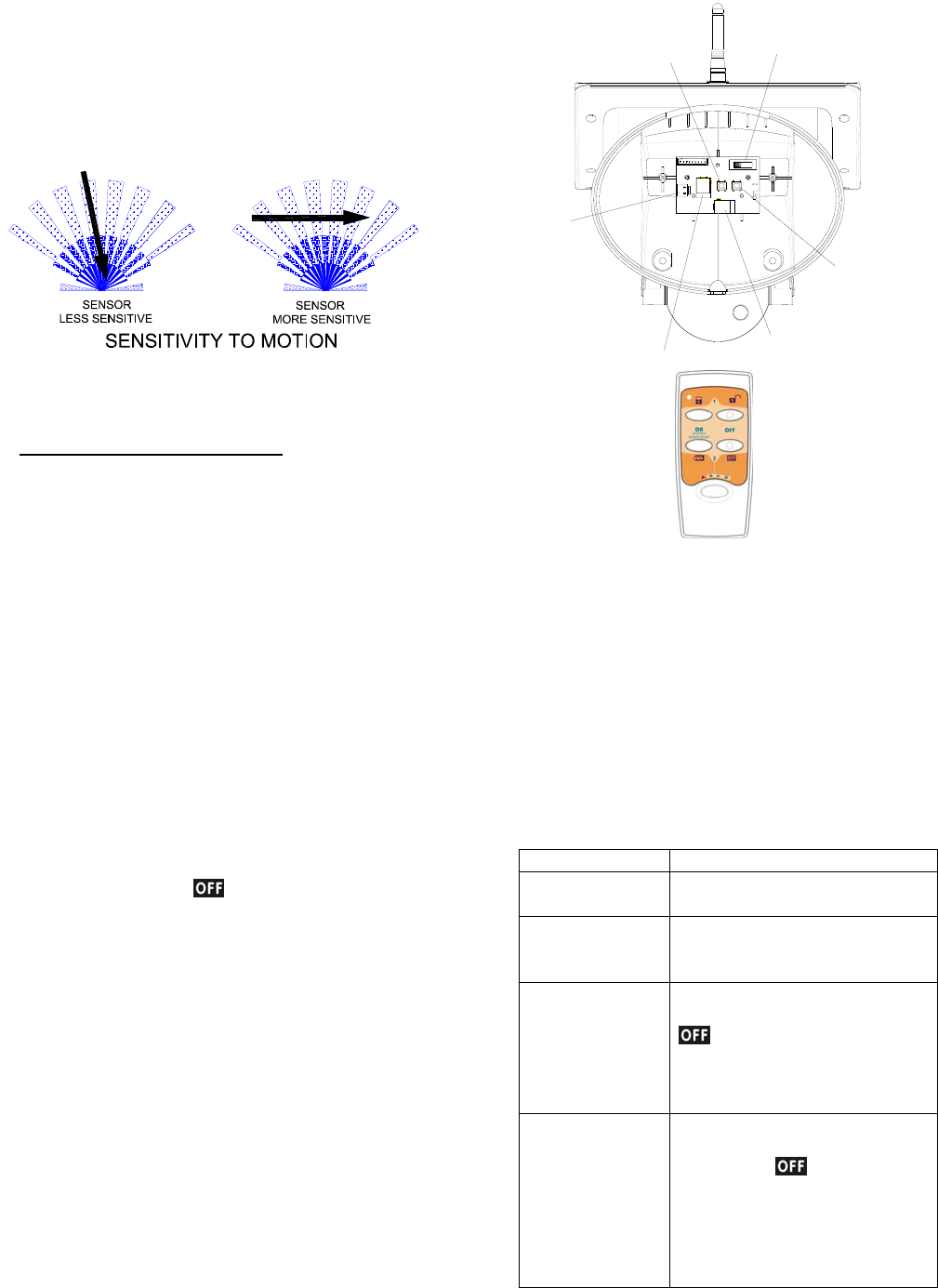
2. Detecting sensitivity: A passive infrared sensor operates by
detecting the
objective
movement and
heat. When the
temperature of the
2
moving object and its surrounding area are close in value, it
may reduce PIR’s sensitivity. The motion detector’s infrared
beams radiate outward like the slat of a wooden fence.
Prior to mounting, keep in mind that the motion sensor is
more sensitive to the motion that crosses these “slats”, and
less sensitive to the motion that moves directly towards the
sensor.
The passive infrared sensor has a detection coverage of
80 degree at 8m away.
3. Keep a light source during nighttime: The camera cannot
work in total darkness. Please bear in mind the camera's
viewing area must be illuminated with a suitable light source
during nighttime.
Setting
Learning the ID code
1. Undo and remove the fixing screw from the bottom edge of
the front cover. Carefully pull the front cover away from
the back plate.
2. By using either 6V/1.2Ah or 7.5V DC/300mA as its power
sources, the PIR Camera will start warming up and the
Status LED will be on steadily.
3. Press and hold the learn switch (SW1) on the rear of front
cover for more than 3 seconds until the Status LED on the
PIR Camera flashes. The PIR Camera enters the ID code
learn mode and the Status LED will flash once per second.
The user has a 30-second to emit the ID code of remote
control (SR103) to the PIR Camera.
4. Set the 4-position slide switch to ‘A’ position on the remote
control by pressing the button for more than 5
seconds, enabling it to emit the ID code to the PIR Camera.
5. The Status LED on the PIR Camera will be on again after
changing from flashing to illuminating for 3 seconds then off.
The ID code has been learnt successfully.
6. If failure to learn the ID code within 30 seconds, the Status
LED will flash three times rapidly before reverting to warm
up period and the Status LED will be on steadily.
Solar Power Jack
Learn Switch
Reset Switch
Channel Switch
Connector
DC Adaptor Jack
Cleaning out the ID code
1. Under any mode, press and hold the learn switch (SW1) on
the rear of front cover for 3 seconds until the Status LED
flashes. Release the switch and the Status LED will flash
once every second.
2. Press the learn switch again until the Status LED is off. The
PIR Camera will revert to the last mode. The ID code has
been cleaned out entirely.
Status LED indication
The indication of Status LED on the PIR Camera may help you
judge if the ID code has been learnt properly.
Status LED indication
Enter ID code
learn mode
LED flashes once per second
Fail to learn the
ID code under ID
code learn mode
LED flashes 3 times rapidly before
exit
ID codes have
been learnt
LED flashes after entering ID code
learn mode. After pressing the
button on the remote control
for 5 seconds, the PIR Camera will
exit the present learn mode and
revert to the last mode
Up to 12 ID codes
have been learnt
LED flashes once per second after
entering ID code learn mode. After
pressing the button on the
remote control, the Status LED of
PIR Camera flashes three time
rapidly before exit the present
learn mode and revert to the last
mode
3
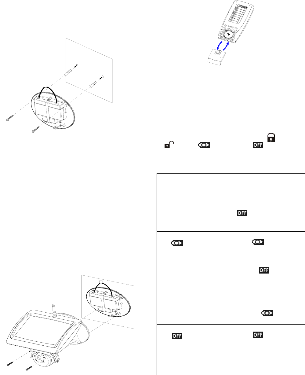
Installation
Step 1: Install the camera
1. Use the fixing template provided to mark the position of the
four fixing holes. Drill four 5mm-diameter holes.
2. Mount back plate by inserting two screws into fixing holes
on the top edge of back plate.
3. Adjust the “Channel switch” (SW3) to set up a channel.
And remember which channel you selected.
4. Plug the power connector of the rechargeable battery to
the connector located on the rear of front cover.
5. If fitted, plug the solar panel connecting wire or DC adaptor
to the solar power jack or DC adaptor jack located on the
rear of front cover.
6. Secure the front cover to the back plate by inserting screws
into two fixing holes on the bottom edge of front cover and
back plate. And then insert the waterproof rubber plug into
the hole at the bottom of front cover.
Step 2: Install Remote Control
1. Remove the battery cover. Fit the 3V Lithium battery in the
compartment provided with +v terminal facing upwardly.
2. By pressing any key, the red LED will illuminate, which
implies that the battery has been inserted properly.
3. Replace the battery cover.
4. To work with the PIR Camera, it is a must to set the
4-position slide switch to “A” position on the remote control.
“A” position is situated in the orange background of plate,
simply follow its orange track for operating (Arm),
(Disarm), (Camera on) and (Camera off).
The buttons’ functions are listed hereunder:
Button Function
4-position
slide switch --
A,B,C,D
A : controllable to PIR Camera (VC451)
B,C & D: controllable to On/Off receiver
(AN121, B410N), Dimmer Receiver
(AD121, B410D).
Learn Pressing the button for about 5
seconds until the Status LED is off will emit
the ID code to the PIR Camera.
Camera On
When the PIR Camera is connected to a
6V/1.2Ah, press the button for one
second on the remote control will enable
the operation of image and voice signal on
the PIR Camera but will disable recording
signal. Fail to press the button within
1 minute will disable the operation of image
and voice signal on the PIR Camera.
If a 7.5V DC/300mA is in use, the image
and voice signal on the PIR Camera will be
always transmitted, the button will
not work for this instance.
Camera Off
When the PIR Camera is connected to a
6V/1.2Ah, press the button for one
second will disable the operation of image
and voice signal and send a stop recording
signal to the wireless receiver (VR111).
When a 7.5V DC/300mA is in use,
p
ress
4
the button for one second will emit a
stop recording signal to the wireless
receiver (VR111).
Arm
When the PIR Camera is connected to a
6V/1.2Ah, press the button for one
second will enter arm mode. When PIR is
triggered, the wireless receiver (VR111)
will be acknowledged with one beep at the
same time.
If a 7.5V DC/300mA is in use, press the
button for one second, the TV screen or
monitor connected to the wireless receiver
(VR111) will temporarily shut down and
then stay on.
Disarm
When the PIR Camera is connected to a
6V/1.2Ah, press the button for one
second will enter disarm mode and the
wireless receiver (VR111) will be
acknowledged with one beep
simultaneously. If you will be active within
the protected area, set the PIR Camera to
disarm mode so as to avoid unnecessary
activation.
If using a 7.5V DC/300mA, press the
button on the remote control for one
second, the TV screen or monitor
connected to the wireless receiver (VR111)
will temporarily shut down and then stay
on.
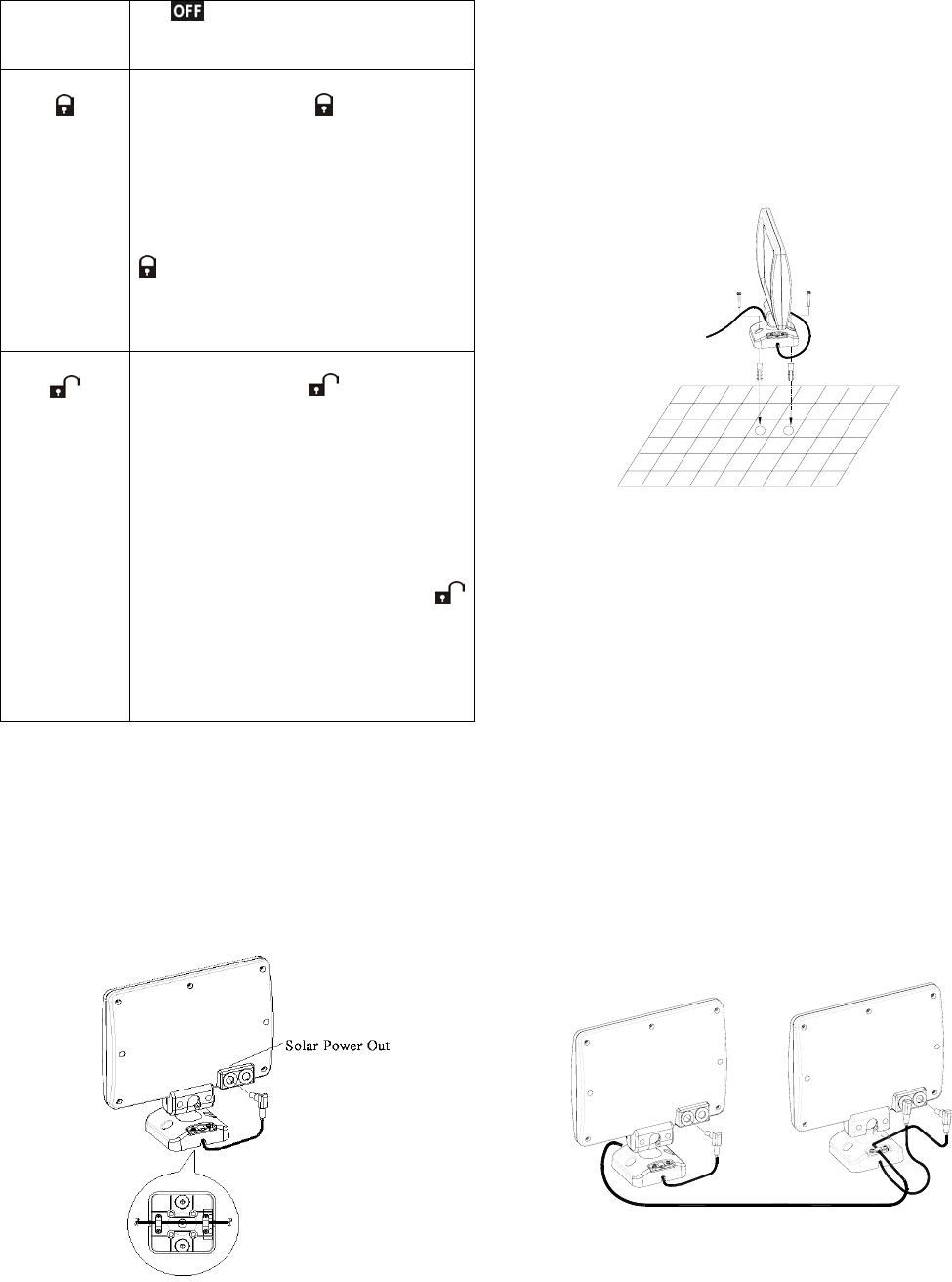
Step 3: Install the Solar Panel (option)
1. Using the fixing template to mark the position of two fixing
holes. Drill two holes with 25mm in depth and 5mm in
width by inserting the plastic wall plugs supplied.
2. Loosen the screws from the strain relief located on the
base of solar panel.
3. Route the solar connecting wire though two strain relief and
fix them in place with screws respectively, leaving 20cm
length of connecting wire for further connection.
4. Plug one end of the jacks with 20cm length of connecting
wire to the ‘solar power out’ of rear side of the solar panel.
5. Plug the other end of the jack to the Camera’s solar power
jack.
6. Fix the base of solar panel to the plastic wall plugs using
two screws provided.
Step 4: Expand the Solar Panel (option)
1. Using the fixing template to mark the position of two fixing
holes. Drill two holes with 25mm in depth and 5mm in
width by inserting the plastic wall plugs supplied.
2. Loosen the screws from the strain relief located on the base
of solar panel.
3. Route the solar connecting wire though two strain relief and
fix them in place with screws respectively, leaving 20cm
length of connecting wire for further connection.
4. Plug one end of the jacks with 20cm length of connecting
wire to the ‘solar power out’ of rear side of the solar panel.
5. Plug the other end of the jack to the ‘solar power in’ of the
rear side of the first solar panel. Fix its solar connecting
wire to the strain relief of the base of solar panel, using the
screws provided.
2
nd. 1
st.
6. Fix the base of solar panel to the plastic wall plugs using
two screws provided.
5
Operating Instruction
1. A 9 volt battery can be used only if the battery level of 6V
1.2Ah drops and solar panel cannot be charged.
2. The solar panel and DC power adaptor cannot be
implemented at the same time.
3. The PIR Camera is equipped with voltage auto switching
function:
a. Power saving mode
When the PIR Camera is connected to a 6V/1.2Ah
rechargeable battery, it will warm up for about 1 minute
and its Status LED will illuminate steadily. The triggered
signal of 2.4GMz may control the VCR/DVR to record or
stop recording through wireless receiver (VR111). Once the
PIR Camera is triggered, it will send a start recording signal
for about 30 seconds. After 30-second is expired, it will
emit a stop recording signal to the wireless receiver
(VR111). During 30-second countdown, if the PIR Camera
has been triggered again, the countdown will be extended
for another 30 seconds.
b. Ordinary mode
When the PIR Camera is connected to a 7.5V DC/300mA
DC adaptor, it will warm up for about one minute and its
Status LED will be on steadily.
The 2.4GMz will always emit radio signal in spite of the PIR
Camera being triggered or not. The triggered signal of
2.4GMz may control the VCR/DVR to record or stop
recording through wireless receiver (VR111). Once the PIR
Camera is triggered, it will send a start recording signal for
about 30 seconds. After 30-second is expired, it will emit
a stop recording signal to the wireless receiver (VR111).
During 30-second countdown, if the PIR Camera is
triggered again, the countdown will be extended for another
30 seconds.
6
Troubleshooting
Status Possible Cause Recommendation
VC451 PIR Camera
Status LED during warm up not on a. Reverse polarity
b. Low battery
a. Relocate battery polarity
b. Insert a 9V battery and have it
charged to a 6V rechargeable battery
Ambiguous image under observation a. radio channel interference
b. Distance between Receiving and
Transmission too far or radio signal
has been blocked
a. Adjust channel to avoid radio
interference. Ensure channel is the
same as set in the wireless receiver
(VR111)
b. Reposition the PIR Camera or the
wireless receiver (VR111)
SR103 Remote Control
No reaction by pressing any button on
the remote control
a. Reverse polarity
b. depleted battery
a. Refit the battery with correct polarity
b. Replace a new battery
No reaction to PIR Camera by pressing
button on the remote control
a. ID code learning has not been
undertaken
b. Incorrect ID code learning process
a. Follow ID code learning process
indicated on the operating instruction
b. Redo ID code learning process
according to the operating instruction
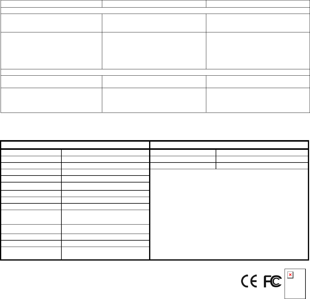
Specifications
VC451 SR103
Picture Type Color CMOS Battery Type CR2032 3V x 1
TV System PAL/NTSC Transmitting Range 70 meters min. (in an open space)
Sensitivity 3Lux@F1.2 Transmitting Frequency 315MHz or 433MHz
Lens Angle 56° Diagonal
Lens 6.0mm F2.0
Camera Angle Left & Right 80°± 5
°, Down 50°
Microphone Build in
Transmitting Frequency 2400~2483MHz (for 4 channels)
Receiving Frequency 315MHz or 433MHz
Battery 1 x 9V back up battery, 1x 6V
rechargeable solar battery
Power Supply Source Solar Panel (110*160mm)
Channel Switch 4 positions for 1~4 selection
PIR Warm up time About 1 minute
PIR Detect ion
Distance/Angle 8M/80° (under 28°C 85% RH)
© 2007 Everspring Industry Co., All Rights Reserved. A501110699R
Mobile of end product
Federal Communication Commission Interference Statement
This equipment has been tested and found to comply with the limits for a Class B digital device, pursuant to Part
15 of the FCC Rules. These limits are designed to provide reasonable protection against harmful interference
in a residential installation. This equipment generates, uses and can radiate radio frequency energy and, if not
installed and used in accordance with the instructions, may cause harmful interference to radio communications.
However, there is no guarantee that interference will not occur in a particular installation. If this equipment
does cause harmful interference to radio or television reception, which can be determined by turning the
equipment off and on, the user is encouraged to try to correct the interference by one of the following measures:
- Reorient or relocate the receiving antenna.
- Increase the separation between the equipment and receiver.
- Connect the equipment into an outlet on a circuit different from that to which the receiver is connected.
- Consult the dealer or an experienced radio/TV technician for help.
7
This device complies with Part 15 of the FCC Rules. Operation is subject to the following two conditions: (1)
This device may not cause harmful interference, and (2) this device must accept any interference received,
including interference that may cause undesired operation.
FCC Caution: Any changes or modifications not expressly approved by the party responsible for compliance
could void the user's authority to operate this equipment.
Important Note:
FCC Radiation Exposure Statement:
This equipment complies with FCC radiation exposure limits set forth for an uncontrolled environment.
7
This transmitter must not be co-located or operating in conjunction with any other antenna or transmitter.
Warning:
Do not dispose of electrical appliances as unsorted municipal waste, use separate collection facilities.
Contact your local government for information regarding the collection systems available.
If electrical appliances are disposed of in landfills or dumps, hazardous substances can leak into the
groundwater and get into the food chain, damaging your health and well-being.
When replacing old appliances with new once, the retailer is legally obligated to take back your old appliance for
disposal at least for free of charg