Exalt Wireless 105P25M 5 GHz Point to Point Fixed Link Radio Module User Manual r manual LMAfinal
Exalt Communications Inc. 5 GHz Point to Point Fixed Link Radio Module r manual LMAfinal
UserManual.wiki
>
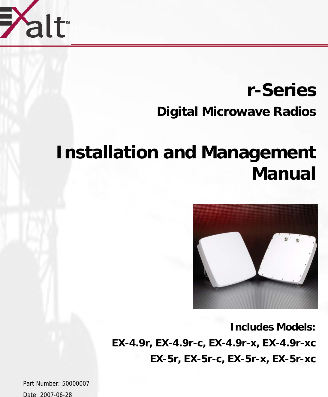
Exalt Wireless
>
105P25M User Manual
>
Host Manual r
Contents
1.
Host Manual r
2.
Host Manual i
3.
Module Manual
4.
i series manual
5.
EX 5 series user manual
6.
R series user manual
7.
User Manual 1
8.
User Manual 2
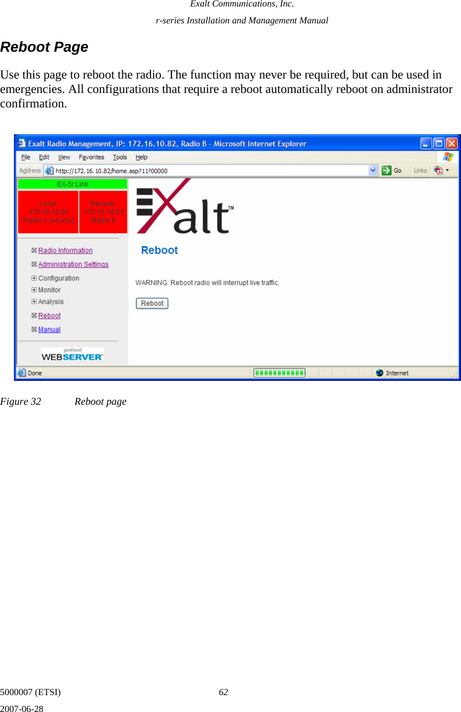
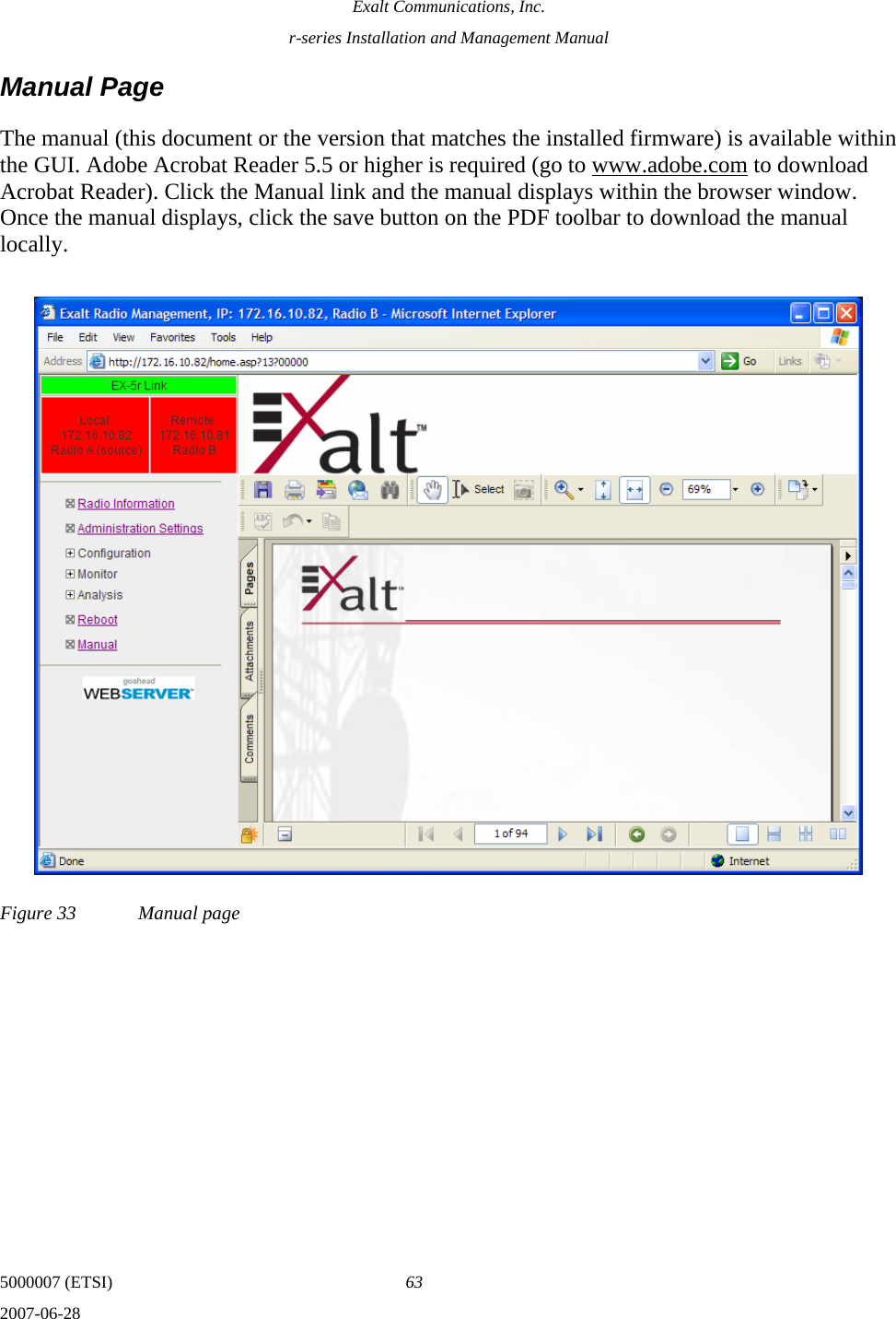
Host Manual r
Navigation menu
Upload a User Manual
Namespaces
Wiki Guide
HTML
PDF
Info
Views
User Manual
Discussion / Help
Navigation