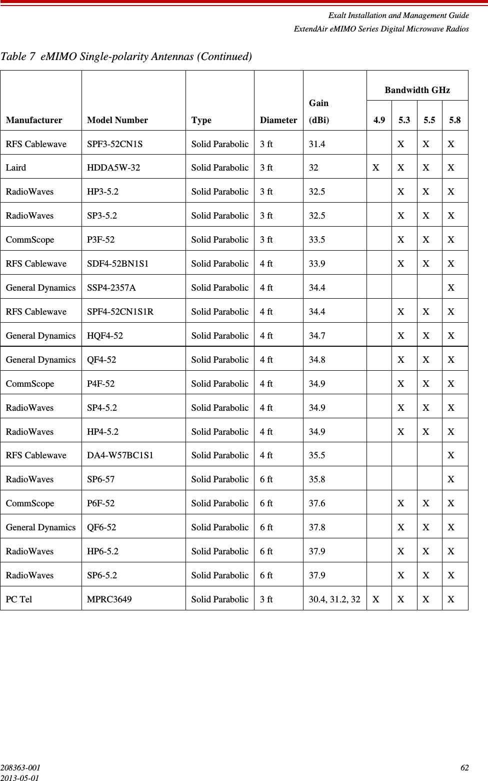
Exalt Wireless 105P25U eMIMO 100 User Manual Installation Manual
Exalt Wireless, Inc. eMIMO 100 Installation Manual
UserManual.wiki
>
Exalt Wireless
>
105P25U User Manual
>
Installation Manual
Contents
1.
Installation Manual
2.
User Manual
Installation Manual
Navigation menu
Upload a User Manual
Namespaces
Wiki Guide
HTML
PDF
Info
Views
User Manual
Discussion / Help
Navigation
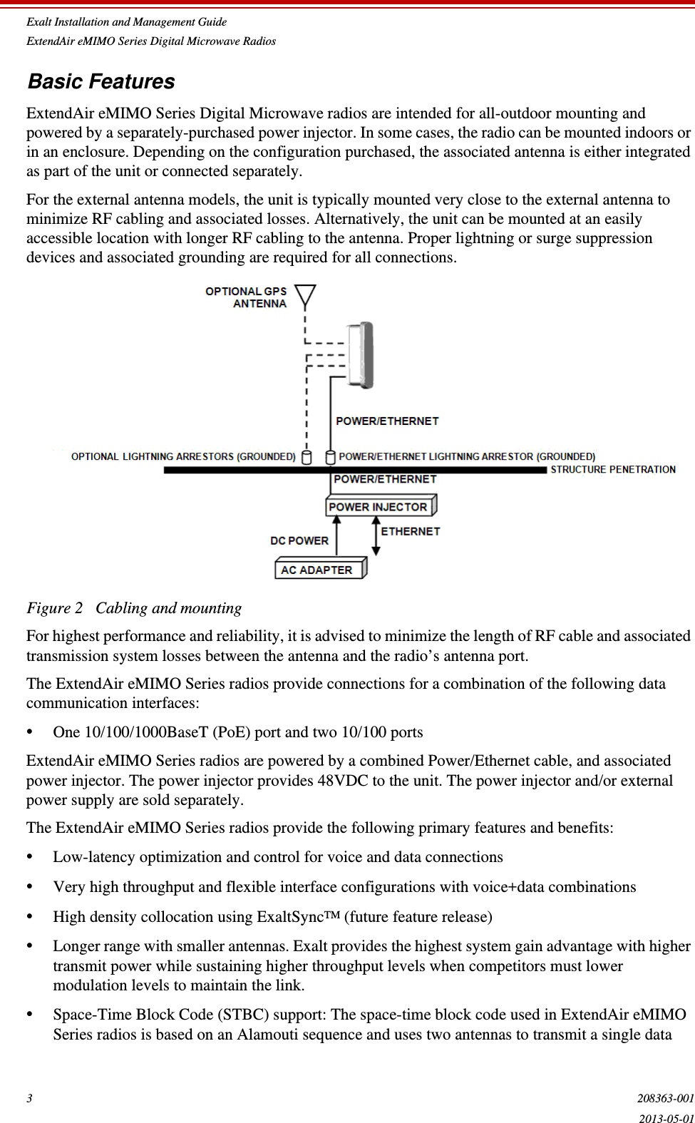
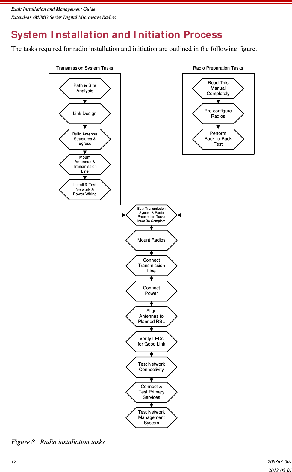
![Exalt Installation and Management GuideExtendAir eMIMO Series Digital Microwave Radios89 208363-0012013-05-01Exalt Limited Hardware Warranty Software License and RMA Procedures AgreementTHIS IS AN AGREEMENT BETWEEN YOU AND EXALT COMMUNICATIONS, INC. ("EXALT"). BY EXECUTING OR OTHERWISE ACCEPTING THIS AGREEMENT OR BY USING THE EXALT PRODUCT WITH OR FOR WHICH THIS AGREEMENT IS PROVIDED ("PRODUCT"), YOU ARE AGREEING TO ALL OF THE BELOW TERMS AND CONDITIONS. IF YOU DO NOT AGREE WITH THESE TERMS AND CONDITIONS, YOU SHOULD NOT USE THE PRODUCT AND RETURN IT TO YOUR PLACE OF PURCHASE. "YOU" MEANS THE LEGAL (END USER) ENTITY THAT PURCHASED THE PRODUCT.1Exalt Limited Hardware Warranty a. Exalt warrants solely to the original purchaser ("Purchaser") that the Exalt hardware product that this Agreement is provided with or for (the "Hardware Product") will substantially conform in all material respects to the relevant Exalt published specifications that apply at the time of manufacture of such Hardware Product for one (1) year from the date of purchase of Hardware Product by Purchaser (the "Warranty Period"). Purchaser may elect to extend the Warranty Period by one additional year as set forth below. Proof-of-purchase in the form of an invoice, payment of invoice, or delivery waybill must be supplied, if requested by Exalt, in case of any dispute of warranty start date. b. In the event Purchaser notifies Exalt during the Warranty Period of a defective Hardware Product (material nonconformance with the published specifications), Exalt shall within the Warranty Period, at its own option either: (A) use reasonable efforts to remedy any reproducible Hardware Product defect covered by this limited warranty within a reasonable period of time; (B) replace the defective Hardware Product with a functionally equivalent product (repair parts and products may be either reconditioned or new, but, if reconditioned, shall be of the same quality as new parts or products); or (C) if Exalt determines that it is unable to repair or replace such Hardware Product, Exalt (or its applicable reseller) will refund to Purchaser the amount actually paid by Purchaser for the applicable Hardware Product.c. All replaced parts become the property of Exalt. Exalt may, at its sole option, refuse to accept as defective any Hardware Product that (i) is subject to the exclusions set forth below; or (ii) cannot be demonstrated to be defective by Exalt and Purchaser is unable to provide adequate information describing how the Hardware Product failed. Such Hardware Product will, at Purchaser's option and expense, either be: (a) returned to Purchaser in the state received, or (b) repaired and returned to Purchaser. Repaired or replaced Hardware Product will be warranted for the remainder of the original Warranty Period, but not less than ninety (90) days.2Timely Registration May Extend Limited Hardware Warranty Period Purchaser may elect to extend the one (1) year Warranty Period to a two (2) year Warranty Period by registering the Hardware Product with Exalt within ninety (90) days of Hardware Product purchase (all requested registration information must be provided in clear and accurate form within such 90 day period). [Product registration may be performed by completing and submitting the product registration form on www.exaltcom.com/ProductRegistration ]3Limited Hardware Warranty Exclusions This limited warranty will not apply to: (A) any Hardware Product that: (i) has been modified or altered by any party other than Exalt; (ii) has been subject to accident, misuse, abnormal wear and tear, neglect, or mistreatment; (iii) has been damaged during installation of the Hardware Product;](https://usermanual.wiki/Exalt-Wireless/105P25U.Installation-Manual/User-Guide-1995969-Page-88.png)