Exavera Technologies VF2200 RFID Reader User Manual
Exavera Technologies Inc. RFID Reader
user manual

Installation Guide:
VeraFi™ and VeraRelay™
PRELIMINARY CONTENT ONLY

2
Copyright © 2005-2006, Exavera Technologies Incorporated All rights reserved. Patents pending.
No part of this documentation may be reproduced in any form without written permission from
Exavera Technologies Incorporated
Exavera Technologies Incorporated reserves the right to revise this documentation and to make
changes without notification of such revision or change.
THE SYSTEM, DOCUMENTATION AND SERVICES ARE PROVIDED “AS IS” WITHOUT
WARRANTY OF ANY KIND. EXAVERA TECHNOLOGIES INCORPORATED DOES NOT
WARRANT THAT THE SYSTEM WILL MEET CUSTOMER'S REQUIREMENTS, OR THAT
THEIR OPERATION WILL BE UNINTERRUPTED OR ERROR-FREE, OR THAT ANY ERRORS
CAN OR WILL BE FIXED. COMPANY HEREBY DISCLAIMS ALL OTHER WARRANTIES,
EXPRESS OR IMPLIED, ORAL OR WRITTEN, WITH RESPECT TO THE SYSTEM AND
SERVICES INCLUDING, WITHOUT LIMITATION, ALL IMPLIED WARRANTIES OF TITLE,
NON-INFRINGEMENT, INTEGRATION, MERCHANTABILITY OR FITNESS FOR ANY
PARTICULAR PURPOSE AND ALL WARRANTIES ARISING FROM ANY COURSE OF
DEALING OR PERFORMANCE OR USAGE OF TRADE.
EXAVERA TECHNOLOGIES INCORPORATED SHALL NOT BE LIABLE CONCERNING THE
SYSTEM OR SUBJECT MATTER OF THIS DOCUMENTATION, REGARDLESS OF THE FORM
OF ANY CLAIM OR ACTION (WHETHER IN CONTRACT, NEGLIGENCE, STRICT LIABILITY
OR OTHERWISE), FOR ANY (A) MATTER BEYOND ITS REASONABLE CONTROL, (B) LOSS
OR INACCURACY OF DATA, LOSS OR INTERRUPTION OF USE, OR COST OF PROCURING
SUBSTITUTE TECHNOLOGY, GOODS OR SERVICES, (C) INDIRECT, PUNITIVE,
INCIDENTAL, RELIANCE, SPECIAL, EXEMPLARY OR CONSEQUENTIAL DAMAGES
INCLUDING, BUT NOT LIMITED TO, LOSS OF BUSINESS, REVENUES, PROFITS OR
GOODWILL, OR (D) DIRECT DAMAGES, IN THE AGGREGATE, IN EXCESS OF THE FEES
PAID TO IT HEREUNDER FOR THE SYSTEM OR SERVICE GIVING RISE TO SUCH
DAMAGES DURING THE 12-MONTH PERIOD PRIOR TO THE DATE THE CAUSE OF ACTION
AROSE, EVEN IF COMPANY HAS BEEN ADVISED OF THE POSSIBILITY OF SUCH
DAMAGES. THESE LIMITATIONS ARE INDEPENDENT FROM ALL OTHER PROVISIONS OF
THIS AGREEMENT AND SHALL APPLY NOTWITHSTANDING THE FAILURE OF ANY
REMEDY PROVIDED HEREIN.
All Exavera Technologies products are furnished under a license agreement included with the
product. If you are unable to locate a copy of the license agreement, please contact Exavera
Technologies Incorporated.
Exavera® is a registered trademark owned and licensed by Exavera Technologies Incorporated.
VeraFi™ and VeraReader™ are trademarks owned and licensed by Exavera Technologies
Incorporated.
All other company and product names are or may be trademarks of the respective companies
with which they are associated.

3
Table of Contents
Regulatory Compliance 4
Introduction 6
Audience and Objectives 6
Product Overview 6
How to Get Help 6
Safety 6
Installation 7
Unpack the System 7
Before You Start 9
VeraFi Installation 10
VeraRelay Installation 10
VeraFi Set-up, Connection and Configuration 11
Default IP Address Behavior 11
Accessing the VeraFi Online Web GUI For the First Time 11
Connecting to the VeraFi Locally 12
Assigning an IP Address From the Console Port 12
Assigning Basic Settings 13
LED Display 14
Technical Specifications 15
4
Regulatory Compliance
All Exavera devices are designed to be compliant with rules and regulations in locations they
are sold and will be labeled as required. Any changes or modifications to Exavera
Technologies equipment, not expressly approved by Exavera Technologies, could void the
user's authority to operate the equipment.
When Exavera's devices are professionally installed, the Radio Frequency Output Power will
not exceed the maximum allowable limit for the country of operation.
Antennas: Use only the supplied or an approved replacement antenna. Unauthorized
antennas, modifications, or attachments could cause damage and may violate regulations.
Country Approvals
Regulatory markings are applied to the device signifying the radio(s) are approved
for use in the following countries: United States, Canada.
Operation of the device without regulatory approval is illegal.
Health and Safety Recommendations
Warnings for the use of Wireless Devices
Please observe all warning notices with regard to the usage of wireless devices
Potentially Hazardous Atmospheres
You are reminded to observe restrictions on the use of radio devices in fuel depots, chemical
plants etc. and areas where the air contains chemicals or particles (such as grain, dust, or
metal powders) and any other area where you would normally be advised to turn off your
vehicle engine.
Safety in Hospitals
Wireless devices transmit radio frequency energy and may affect medical electrical
equipment. When installed adjacent to other equipment, it is advised to verify that the
adjacent equipment is not adversely affected.
FCC / EU RF Exposure Guidelines
Reducing RF Exposure—Use Properly
It is advisable to use the device only in the normal operating position.
Remote and Standalone Antenna Configurations
To comply with FCC RF exposure requirements, antennas that are mounted externally
at remote locations or operating near users at stand-alone desktop of similar
configurations must operate with a minimum separation distance of 20 cm from all
persons.

5
Power Supply
Use only an Exavera approved power supply
Operation in the US
The use on UNII (Unlicensed National Information Infrastructure) Band 1 5150-5250
MHz is restricted to indoor use only, any other use will make the operation of this device
illegal.
The available channels for 802.11 b/g operation in the US are Channels 1 to 11. The
range of channels is limited by firmware.
Radio Frequency Interference Requirements—FCC
This equipment has been tested and found to comply with the limits for a Class B digital
device, pursuant to Part 15 of the FCC rules. These limits are designed to provide
reasonable protection against harmful interference in a residential installation. This
equipment generates, uses and can radiate radio frequency energy and, if not installed and
used in accordance with the instructions, may cause harmful interference to radio
communications. However there is no guarantee that interference will not occur in a
particular installation. If this equipment does cause harmful interference to radio or television
reception, which can be determined by turning the equipment off and on, the user is
encouraged to try to correct the interference by one or more of the following measures:
• Reorient or relocate the receiving antenna
• Increase the separation between the equipment and receiver
• Connect the equipment into an outlet on a circuit different from that to which the
receiver is connected
• Consult the dealer or an experienced radio/TV technician for help.

6
Introduction
Audience and Objectives
This document has been created for individuals responsible for installing and configuring the
VeraFi Access Reader and its related components, including the VeraRelay. The guide assumes
that you are a qualified technician familiar with the basic installation procedures and safety
precautions required to install network equipment.
Product Overview
Exavera’s VeraFi Access Reading Point combines an 802.11 a/b/g access point with a long-
range RFID reader. With countless applications, the VeraFi is a vital component in an Exavera
solution that provides identification and location services, facilitates data delivery and automates
business processes.
The VeraRelay is a smaller, plug-in RFID reader, which offers increased resolution within a
flexible and cost-effective deployment model.
How to Get Help
To obtain Technical Assistance, you can contact Exavera’s Customer Support as follows:
• Phone: (603) 570-<to be provided>
• Email: support@exavera.com
• Customer Support Web Site: <to be provided>
Please have the following information available when contacting customer support:
• List of hardware components with serial numbers and revision levels
• System Software version number and revision level
• Error and diagnostic messages with associated LED indications
• Details about recent configuration changes, if applicable
Safety
Before connecting power, review the following safety guidelines and precautions:
• Do not work alone when potentially hazardous conditions exist.
• Check the work area for potentially hazardous conditions (such as wet or moist floors)
and correct the conditions before proceeding.
7
Installation
Unpack the System
Carefully unpack the system and compare the equipment contained in your shipment with the
enclosed packing slip. Notify customer support if there are any discrepancies.
Each VeraFi (Part #: VF-2200) is shipped with the following materials.
Part
Description
Quantity
VeraFi Access
Reading Point
VF-2200
WLAN access point/RFID reader
1
RP-SMA Antenna
VF-W2DB
2 dBi tri-band antenna (included with VF-
2200)
2
Compact Flash Card
Part #: VF-CFO256
256M Compact flash card for VeraFi
(512M card part #: VF-CF0512)
1
Installation Guide
Configuration and installation instructions
1
Mounting Template
Template for wall mounting VeraFi
1
Plastic Anchors #8-
10x1”
Wallboard anchor
2
Panhead Screws
#8-1.25” Panhead screws
2
Additional Optional Items
Part
Description
Quantity
Antenna
Part #: VF-P5DB
5 dBi tri-band antenna
2
Power Supply
Part #: VF-PWR-NA
Wall wart AC to DC power supply
1
Console Cable
Part #: VF-CONCABL
DB9 to 6 pin DIN
1
8
VeraRelays are shipped independently of the VeraFi Access Reading Points
Part
Description
VeraRelay
Part #: VR-320
Plug-in RF reader
VeraRelay (pass-through)
Part #: VR-310
Plug-in RF reader with pass-through outlet

9
Before You Start
Before you install the VeraFi, make sure the computer you are using is connected to the same
network as the unit you are trying to configure. You should obtain the following information from
your network administrator:
• Whether PoE or the power supply will be used.
• A static IP address for the VeraFi, if not connected to a DHCP server
• A default gateway address and subnet mask if needed.
• A system hostname for the access point.
• The case sensitive wireless service set identifier (SSID) for your wireless network.
• Security type (WEP, WPA, WPA2, etc.) and key(s) to secure your wireless network.
• WLAN type and channel assignment.
10
VeraFi Installation
1. Using the wall-mount template, mark the 2 mounting holes to be drilled.
2. With a 3/16" bit, drill the 2 marked holes.
3. Using a hammer gently tap the 2 plastic anchors into the holes.
4. Screw panhead screws into anchors (leaving ¼” of screw exposed) and gently slide
VeraFi case onto screws.
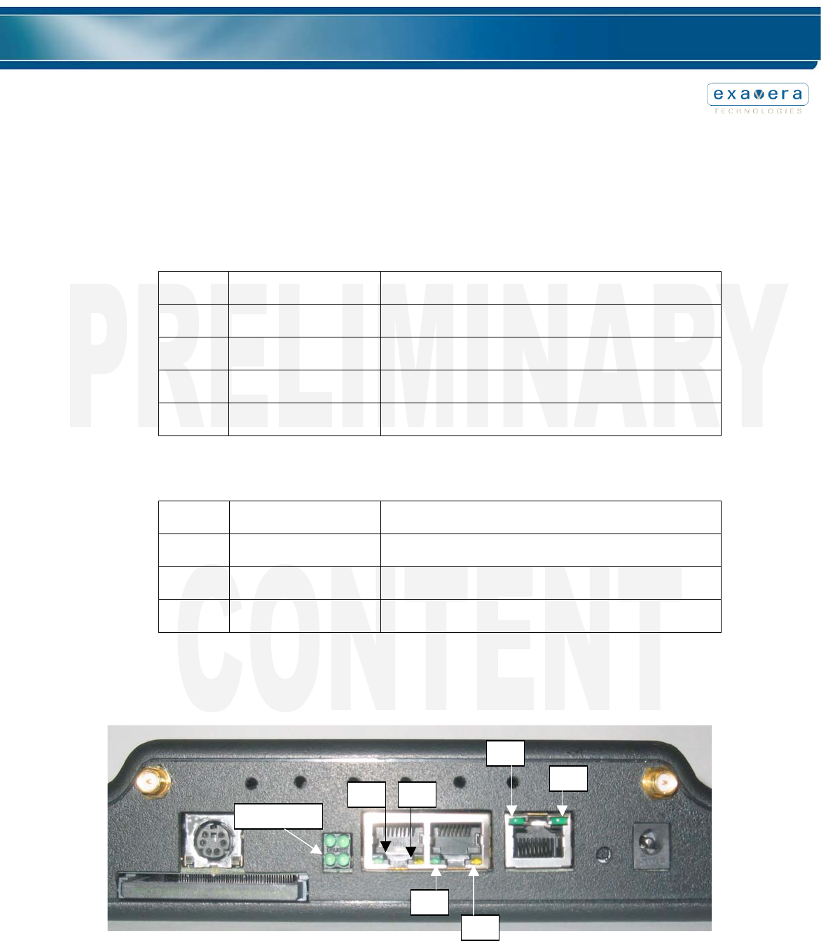
5. Attach all necessary cabling to the ports on the VeraFi (see Figure 1 – NOTE: only one
power source is required; if PoE is utilized, the Power jack will remain unused).
6. If using the external power supply, once the installation is complete, attach the power
supply to the unit’s power jack, then plug the unit in.
Figure 1
VeraRelay Installation
The VeraRelay plugs into any standard AC wall outlet, with placement based on a customized
site survey and resulting deployment plan. As with any electrical appliance, care should be taken
around electrical outlets.
Console Port
Power
Uplink/PoE

11
VeraFi Set-up, Connection and Configuration
This chapter will describe how to setup the basic settings on the VeraFi for the first time. You are
able to configure all settings using the Online Web GUI through a web browser.
Default IP Address Behavior
The VeraFi you are configuring will boot with a default static IP address of 192.168.1.1. This
known address will allow you to point a web browser to the access point and configure basic
settings.
Accessing the VeraFi Online Web GUI For the First Time
To browse the VeraFi’s configuration page:
1. Enter the default IP address (192.168.1.1) in the browser address line. You will be
notified of a possibly untrustworthy certificate. Choose to accept the certificate. A
password window will appear.
2. Enter the default username (admin) and the default password (admin).
3. The VeraFi Web GUI Home page appears showing a menu of seven configuration
headings labeled:
• Home
• RFID Location
• General Networking
• Wireless Networking
• System Settings
• Utilities
• User Access
4. Navigate to the “General Networking” page by clicking on its heading in the menu.
5. The “IP Assignment Source” defaults to “User Supplied.” If you wish to use Static IP,
keep this selection and fill in the IP Address, Subnet Mask, and Default Gateway fields.
6. If you would prefer to have the IP assigned dynamically, select “DHCP” for the
assignment source, and optionally select a specific Lease Time and whether DNS
information should be obtained from the DHCP server as well.
7. Click “Apply” to activate your selections.
NOTE: Any changes made in the Web GUI require that you click “Apply” at the bottom
of the page for those changes to take effect. Once applied successfully, the changes
will persist on the system even after a reboot or loss of power.

12
Connecting to the VeraFi Locally
If you need to connect to the VeraFi locally (without connecting the device to a wired LAN), you
can connect a PC to its console port using a DB-9 to 6 pin DIN serial cable. The Exavera part
number for this cable is: VF-CONCAB. Follow these steps to operate the CLI via the console port
(see Figure 3):
1. Connect the DB-9 female end of the cable to a COM port on your pc.
2. Connect the 6 pin DIN to the port labeled “Console Port” (see Figure 1) on the
VeraFi.
3. Set up a terminal emulator to communicate with the VeraFi. Use the following
settings for the terminal emulator connection: 115,200 baud, 8 data bits, no
parity, 1 stop bit, no flow control.
NOTE: Once you have finished making changes via the console cable you should
remove the serial cable from the access point.
Assigning an IP Address From the Console Port
Once you have opened the terminal emulator and have successfully connected to the VeraFi you
are now able to issue commands to configure the unit. To assign an IP address and Mask the
following commands are used:
cfg_net_ip_set “ip address”
cfg_net_mask_set “subnet mask”
For example, to set the unit’s IP address to 192.168.100.1/24, the commands would be:
cfg_net_ip_set “192.168.100.1”
cfg_net_mask_set “255.255.255.0”
NOTE: The use of quotation marks around the IP address parameter are required for
the command to succeed.
Once set, use the Online Web GUI to verify and “Apply” these changes.
NOTE: Any changes made in the Web GUI require that you click “Apply” at the bottom
of the page for those changes to take effect. Once applied successfully, the changes
will persist on the system even after a reboot or loss of power.

13
Assigning Basic Settings
Once you have been able to browse the unit’s web page successfully you have the ability to
assign all settings via the web browser. The following list shows all of the settable options for the
VeraFi from the web page.
1. RFID Location
o Enable RFID
o Location Server Hostname or IP Address
2. General Networking
o Enable LAN Ports
o Select IP Assignment Source
o IP Address
o IP Network Mask
o Default Gateway
o DHCP Lease Time
o DHCP DNS Info
3. Wireless Networking
o Enable WLAN
o Configurable SSID (up to 32 characters)
o Broadcast SSID
o WLAN Radio Mode selection
o WLAN Channel selection
o WLAN Authentication Type (Open, Shared-key, PSK, 802.1X-EAP)
o PSK/Passphrase
o Radius Servers
o Encryption (AES, TKIP, WEP104, WEP0)
o WEP Keys
o WLAN ACL MAC Address List
o WLAN ACL Mode (Allow, Deny, Disabled)
4. System Settings
o System Hostname
o Primary Domain
o DNS Servers
o SysLog Server
o SNMP Agent Enable
o SNTP Servers
o Time Zone
o Tracking of Daylight Saving Time
5. Utilities
o View/Download Saved Configuration
o Revert to previous saved configuration
o Configuration File Upload
o System Software Installation
o System Reboot
6. User Access
o Username/Password Add and Remove
14
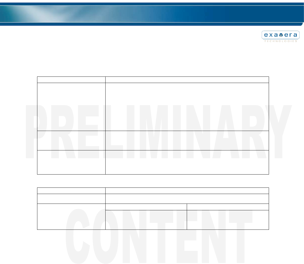
LED Display
The following list defines the LED’s used on the VeraFi and what each color represents during
normal activity.
QUAD LEDs
Quad
Position
LED/Label
Description
Lower
right
PWR
Green when unit is powered
Upper
right
WLAN
Blinking green when enabled
Upper
left
OPT
Blink green when Compact Flash is accessed
Lower
left
RAD
Blinking green when enabled
JACK LEDs
Diagram
label
LED/Label
Description
A
B
UPLINK
Solid green for link
blinking for 100mbit activity
C
D
LAN1
Green/blinking for 100mbit link/activity
Yellow/blinking for 10mbit link/activity
E
F
LAN2
Green/blinking for 100mbit link/activity
Yellow/blinking for 10mbit link/activity
Quad LEDs
C
D
E
F
A
B
15
Technical Specifications
VeraFi
Specification
Description
Power
Estimated maximum power consumption: 12.95W
It can be sourced from either of two possible power inputs:
PoE - Patriots is an IEEE 802.3af compliant Class 0 PD (Powered Device). The
voltage range is 44-57Vdc on this interface (although it can operated as low as 37V).
The approx. numbers from IEEE 802.3af are: 57Vdc@230mA, 44Vdc@300mA, and
37Vdc@350mA.
Power Jack Connector- 24Vdc@540mA (Use only part VF-PWR-NA)
Environmental Operating Ranges
Operating temperature: 0o to 40oC (32o to 105oF)
Non-operating temperature: -40o to 70oC (-40o to 158oF)
Humidity: 0 to 90% non-condensing
Dimensions
Height: 127.83 mm (5.03 in)
Width: 192.02 mm (7.56 in)
Depth: 44.7 mm (1.77 in)
Weight: 428.08 g (15.1 oz)
VeraRelay
Specification
Description
Power
Standard AC outlet
Standard Enclosure
Pass-through Enclosure
Dimensions
Height: 103.77mm (4.06 in)
Width: 55.83mm (2.2 in)
Depth: 36.24mm (1.43 in)
Weight: 130.41g (4.6 oz)
Height: 102.53mm (4.04 in)
Width: 55.60mm (2.2 in)
Depth: 64.26mm (2.5 in)
Weight: 175.77g (6.2 oz)