Exicom EX7100-1 Base station transmitter User Manual Hawk Installation Manual
Exicom Limited Base station transmitter Hawk Installation Manual
Exicom >
Users manual etc

EX7100 Technical Manual – VHF Fan Assembly
©2001 Exicom Technologies (1996) Ltd VHF Fan-1 Issue 0 – May 2001
VHF EX7100 Fan Box (Type 8057)
1.0 General
A Fan Box has been designed to assist with the cooling of the PA Heatsink casting for the
VHF EX7100 product range.
The Fan Box consists of a metal enclosure with two (2) fan assemblies that fits over (and
is bolted to) the existing PA Heatsink. DC Supply for the fans is provided by the existing
DC input socket on the rear of the EX7100 Terminal.
1.0.1 Date of release
All VHF EX7100 Terminals produced after 1 May 2001 will include the Fan Box (Product
Code 61-8057-00002). It will be factory-fitted during the manufacturing process.
1.0.2 Terminal Mounting Considerations
The Fan Box fits snugly around the existing PA Heatsink casting and does not adversely
affect the overall width or depth of the EX7100 Terminal but does affect the height.
The top of the Fan Box will be approximately 40mm above the top cover of the EX7100
Terminal. However, as it is recommended that a gap of at least 2U (89mm) is left
above/below the EX7100 Terminal and any other equipment, this additional height should
not become a problem for standard 19” Rack mounting.
2.0 Removal Instructions
The following sections detail the steps necessary to remove the Fan Box to allow access
to the PA Heatsink casting.
2.0.1 Tools required
> M5 Short Arm Hex Wrench
> Medium sized insulated flat-blade screwdriver
2.0.2 Procedure
1) It is necessary to isolate the EX7100 Terminal from any mounting shelf prior to removal of
the Assembly.
(Depending on the lengths of any antenna, telephone or DC power cables, it will probably
be necessary to remove these to allow unobstructed Terminal access)
2) Switch off the DC supply to the Terminal (if not already removed) and place the Terminal
on a clean, flat surface.
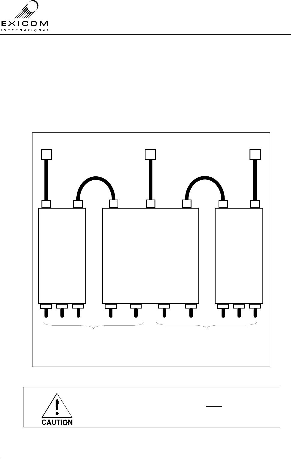
3) Refer to Figure 1 (overleaf) and remove the 2x M6 socket cap screws and washers from
the Fan Box Assembly using the Short arm Hex wrench. The removed screws and
washers should be put to one side for future replacement.

EX7100 Technical Manual – VHF Fan Assembly
©2001 Exicom Technologies (1996) Ltd VHF Fan-2 Issue 0 – May 2001
Figure 1: Assembly connected to the EX7100 Terminal
4) Remove the Fan Box DC supply cable from the rear of the EX7100 Terminal, taking
careful note of the existing wire connections for future re-assembly (the BROWN wire is
connected to the +ve input and the BLUE wire is connected to the –ve input)
5) Carefully remove the Fan Box Assembly from the EX7100 Terminal. Access is now
available to the PA Heatsink casting.
6) Refer to Section 7 of the EX7100 Technical Manual for further information regarding the
replacement of the Heatsink casting and/or the PA Assembly.
7) Reverse the above-mentioned steps as required to re-assemble the Fan Box.

EX7100 Technical Manual - Mandatory Regulations
©1999 Exicom Technologies (1996) Ltd Regulations-1 Issue 0 – October 2000
Mandatory Regulations
The following information outlines the mandatory regulations governing the installation
and operation of the Exicom EX7100 digital radio link.
Adherence to this information is necessary to ensure regulatory compliance.
1.0 General Requirements
This equipment shall be configured only with those assemblies as specified in the
Technical Manual and shall only be mounted as instructed.
1.0.1 Danger
The Modem/Controller module contains a lithium battery. There is a danger of explosion if
the battery is incorrectly replaced. Replace only with the same or equivalent type
recommended by the manufacturer.
Dispose of used batteries according to the manufacturers instructions. Do not recharge,
disassemble or incinerate.
1.0.2 Warning
This equipment must only be installed and maintained by service personnel.
1.0.3 Access to the Equipment
The EX7100 digital radio link should be installed in a location or environment that
prevents unauthorised access.
1.0.4 Equipment Port and Connector Classifications
The EX7100 digital radio link contains various ports and connectors that are classified as
either Safety Extra Low Voltage (SELV) or Telecommunication Network Voltage (TNV) as
follows:
SELV TNV
> DC Power Input
> G.703 (3x ports)
> I/O
> Sync Data
> Control
> LMS
> Front Panel Test Pin Sockets
> Line Interface Module Connector
Connect SELV circuits on this equipment
only to other SELV compliant circuits as
defined in AS/NZS 3260 and IEC950.
Connect TNV circuits on this equipment
only to other TNV compliant circuits as
defined in AS/NZS 3260 and IEC950

EX7100 Technical Manual - Mandatory Regulations
©1999 Exicom Technologies (1996) Ltd Regulations-2 Issue 0 – October 2000
1.0.5 Telecom Safety Earth
The wire used for safety earthing should be a minimum of 4mm2 and should preferably be
directly connected to an earthing stake driven into the ground
Refer to Section 2.8 of the Technical Manual for specific instructions
2.0 Country-specific Regulations
The following sections detail any regulations that may be required by specific countries
and/or territories.
2.0.1 New Zealand Regulation - PTC 200
• “The grant of a Telepermit for any item of terminal equipment indicates only that
Telecom has accepted that the item complies with minimum conditions for connection
to its network. It indicates no endorsement of the product by Telecom, nor does it
provide any sort of warranty. Above all, it provides no assurance that any item will
work correctly in all respects with another item of Telepermitted equipment of a
different make or model, nor does it imply that any product is compatible with all of
Telecom’s network services.”
• “This equipment may not provide for the effective hand-over of a call to another device
connected to the same line.”
• “IMPORTANT NOTICE
Under power failure conditions, this device may not operate. Please ensure that a
separate telephone, not dependent on local power, is available for emergency use.”
• “Use of pulse dialling, when this equipment is connected to the same line as other
equipment, may give rise to bell tinkle or noise and may also cause a false answer
condition. Should such problems occur, the user should NOT contact the Telecom
Faults Service.”
• “Devices designed to respond to particular ringing cadences may not respond when
used with this equipment.”
• In the event of any problem with this device, it is to be disconnected and a CPE item
connected to one of its terminal ports may be connected directly in its place. The user
should then arrange for the product to be repaired. Should the matter be reported to
Telecom as a wiring fault, and the fault be proven to be due to this product, a call-out
charge will be incurred.”
• “Note that the receive audio line level must not be more than 3dB higher than the
transmit audio line level. (for typical installations using short telephone cable lengths, it
is recommended that the receive audio line level is set for –3dBm)”
• “The maximum number of parallel CPE devices that can satisfactorily be operated on
a single port is two (2)”
• “This unit should be powered from a supply that is compliant with AS/NZS3260 and is
SELV compliant”
EX7100
TECHNICAL
MANUAL

©1999 Exicom Technologies (1996) Limited
All rights reserved. This publication is copyright.
No part of this work may be reproduced or copied in any form or by any means (electrical,
mechanical, photocopying, microfilming, recording or otherwise) without the written permission
of Exicom Technologies (1996) Ltd, Private Bag 50912, Porirua, New Zealand.
Confidentiality
This document contains confidential information which belongs to Exicom Technologies (1996)
Limited. All information is supplied to you in confidence on the basis that it must not be used by
you (except for product evaluation purposes) or disclosed to any person without Exicom
Technologies (1996) Limited’s prior written consent.
Any breach of the above obligation may be restrained by legal proceedings seeking remedies
including injunctions, damages and costs.
Disclaimer
Exicom Technologies (1996) Limited constantly seeks to improve quality and performance.
Therefore, specifications and configurations are subject to change without notice.
Product code: 61-8031-00002

EX7100 Technical Manual - Contents
©1999 Exicom Technologies (1996) Limited i Issue 2 - May 2001
Contents
Page
List of Figures ix
1 Introduction
1.1 General 1-1
1.2 Configuration 1-2
1.2.1 64 kbit/s digital “pipe” 1-2
1.2.2 Six low bit rate voice/fax/data channels 1-2
1.3 About this Manual 1-3
1.4 Terminology 1-3
1.5 EX7100 Specifications 1-4
1.5.1 System Parameters 1-4
1.5.2 Power, Mechanical and Environmental 1-4
1.5.3 Multi-channel Voice and Data Multiplexer 1-5
1.5.4 Data Channel 1-6
1.5.5 System Management 1-6
1.6 System Planning 1-7
2 Installation of Antenna and Equipment
2.1 General 2-1
2.2 Antenna Sites 2-1
2.3 Mounting the Antenna 2-2
2.3.1 Antenna Polarisation 2-2
2.3.2 Antenna Direction 2-3
2.3.3 Antenna Cable Grounding Kits 2-3
2.4 Positioning the EX7100 Terminal 2-4
2.5 Mounting the Terminal in the Rack 2-5
2.6 Cable Connections 2-5
2.6.1 General 2-5
RF Connection 2-5
DC Power Input 2-7
2.7 Terminal Type Specific Connections 2-8
2.7.1 Digital Data Terminal Connections 2-8
Synchronous Data V.35 2-8

EX7100 Technical Manual - Contents
©1999 Exicom Technologies (1996) Limited ii Issue 2 - May 2001
Page
G.703 2-8
2.7.2 Exchange Terminal Connections 2-8
2.7.3 Subscriber Terminal Connections 2-9
2.8 Earthing the Terminal 2-9
2.9 Other Rear Panel Connections 2-9
2.9.1 Control 2-10
2.9.2 LMS 2-10
2.9.3 I/O 2-10
External Site Alarms 2-10
2.9.4 RF 2-10
2.10 Powering Up the Terminal 2-11
2.10.1 General 2-11
2.10.2 Procedure 2-11
2.11 Final Antenna Alignment 2-12
2.11.1 General 2-12
2.11.2 Alignment Sequence 2-12
3 Configuring the Terminal
3.1 General 3-1
3.2 Using the Keypad 3-1
3.3 The User Interface Menu 3-2
3.4 Changing Parameters 3-2
3.4.1 Universal Parameters 3-3
Passwords 3-3
Changing the Time and Date 3-5
Operating Mode 3-5
Link ID 3-6
Terminal Descriptor 3-7
Changing the RF Channel Increment 3-7
Changing the Local Transmitter Frequency 3-8
Changing the Local Receiver Frequency 3-10
Transmitter RF Power Level 3-11
Interface Type 3-11
3.4.2 Data Terminal Parameters 3-12
Tx Data Clock Synchronisation 3-12
Sync Data Polarity 3-13
3.4.3 Exchange Terminal Parameters 3-14
Operating Mode 3-14
Channel Set-up 3-14
Payphone Metering Frequency 3-15
Transmit Audio Line Level 3-16

EX7100 Technical Manual - Contents
©1999 Exicom Technologies (1996) Limited iii Issue 2 - May 2001
Page
Receive Audio Line Level 3-16
3.4.4 Subscriber Terminal Parameters 3-17
Ringer Frequency 3-17
Line Termination Impedance 3-17
Payphone Metering Frequency 3-18
Transmit Audio Line Level 3-19
Receive Audio Line Level 3-19
Telephone Loop Current 3-20
4 Monitoring and Diagnostics
4.1 General 4-1
4.2 Monitoring the EX7100’s Operation 4-1
4.2.1 RF Parameters 4-1
4.2.2 Power Supply Parameters 4-2
4.2.3 Framer Parameters 4-3
4.3 Monitoring a Remote Terminal 4-3
4.3.1 Setting up a Test Link 4-4
4.3.2 Closing the Test Link 4-5
4.3.3 Changing Operating Frequencies Remotely 4-5
4.4 EX7100 Internal Alarms 4-7
4.4.1 Acknowledging an Alarm 4-8
4.4.2 Setting Alarm Priorities 4-8
4.4.3 Link Up Time Alarm 4-9
4.4.4 Low RSSI Alarm 4-10
4.5 Diagnostic Tools 4-10
4.5.1 System Align Mode 4-10
4.5.2 Digital Loopbacks 4-11
Local Loopback 4-12
Remote Loopback 4-12
Enabling Digital Loopbacks 4-12
4.5.3 Analogue Loopbacks 4-13
Local Loopback 4-13
Remote Loopback 4-13
Enabling Analogue Loopbacks 4-14
4.6 Bit Error Rate Testing 4-14
4.6.1 General 4-14
4.6.2 BER Testing an EX7100: End-to-End 4-15
4.6.3 BER Testing an EX7100: Round-Trip 4-17
4.6.4 BER Testing an EX7100: Local Interface 4-17
4.7 Networking EX7100 Terminals 4-18
4.7.1 General 4-18
4.7.2 Interconnection of Local Terminals 4-18

EX7100 Technical Manual - Contents
©1999 Exicom Technologies (1996) Limited iv Issue 2 - May 2001
Page
4.7.3 Accessing Bussed Terminals 4-19
5 Troubleshooting the EX7100
5.1 General 5-1
5.2 Configuration Issues 5-1
6 EX7100 Top and Bottom Cover Removal
6.1 Procedure 6-1
7 Module Descriptions
7.1 General 7-1
General (Non-RF) Modules 7-1
RF Modules 7-1
Line Interface Modules 7-1
7.2 Power Supply Module Type 2964 7-3
7.2.1 General 7-3
7.2.2 Testing and Fault Diagnosis 7-4
General 7-4
Accessing the Power Supply 7-5
Diagnosis 7-5
7.2.3 Alignment 7-7
7.2.4 Module Replacement Procedure 7-7
7.3 VHF Transmitter Module Type 8027 7-9
7.3.1 General 7-9
7.3.2 Testing and Fault Diagnosis 7-10
General 7-10
Accessing the VHF Transmitter Module 7-11
Diagnosis 7-11
7.3.3 Alignment 7-13
Re-tuning of the VHF Transmitter Module 7-13
Carrier Null 7-13
7.3.4 VHF Transmitter Module Replacement Procedure 7-14
7.4 UHF Transmitter Module Type 8053 7-15
7.4.1 General 7-15
7.4.2 Testing and Fault Diagnosis 7-16
General 7-16
Accessing the Transmitter Module 7-17
Diagnosis 7-17
7.4.3 Alignment 7-19
Re-tuning of the Transmitter Module 7-19
Carrier Null 7-20

EX7100 Technical Manual - Contents
©1999 Exicom Technologies (1996) Limited v Issue 2 - May 2001
Page
7.4.4 UHF Transmitter Module Replacement Procedure 7-20
Replacement of the Type 8044 Sub-Module 7-20
Removal of the Transmitter Module 7-22
7.5 VHF RF Power Amplifier Module Type 8028 7-23
7.5.1 General 7-23
7.5.2 Testing and Fault Diagnosis 7-24
VHF RF Power Amplifier Module Testing 7-24
7.5.3 Alignment 7-27
7.5.4 VHF RF Power Amplifier Replacement Procedure 7-27
7.6 UHF RF Power Amplifier Module Type 8048 7-28
7.6.1 General 7-28
7.6.2 Testing and Fault Diagnosis 7-29
UHF RF Power Amplifier Module Testing 7-29
7.6.3 Alignment 7-32
7.6.4 UHF RF Power Amplifier Replacement Procedure 7-32
7.7 VHF Receiver Module Type 8029 7-34
7.7.1 General 7-34
7.7.2 Testing and Fault Diagnosis 7-34
General 7-34
Accessing the VHF Receiver Module 7-35
Diagnosis 7-35
7.7.3 Alignment 7-37
Module Re-tuning 7-37
Receiver Maintenance Adjustments 7-38
7.7.4 VHF Receiver Replacement Procedure 7-38
7.8 UHF Receiver Module Type 8054 7-40
7.8.1 General 7-40
7.8.2 Testing and Fault Diagnosis 7-40
General 7-40
Accessing the UHF Receiver Module 7-40
Diagnosis 7-41
7.8.3 Alignment 7-43
Module Re-tuning 7-43
Receiver Maintenance Adjustments 7-44
7.8.4 UHF Receiver Replacement Procedure 7-44
Removal of the Type 8055 Front-End Module 7-44
Removal of the Receiver Module 7-46
7.9 VHF Duplex Filter Module Type 8013 7-47
7.9.1 General 7-47
VHF Connections 7-47
VHF Mounting 7-47

EX7100 Technical Manual - Contents
©1999 Exicom Technologies (1996) Limited vi Issue 2 - May 2001
Page
7.9.2 Testing and Fault Diagnosis 7-48
General 7-48
Checking RF Connectors 7-48
7.9.3 Alignment 7-48
VHF Module Re-tuning 7-48
7.9.4 VHF Duplex Filter Replacement Procedure 7-50
7.10 UHF Duplex Filter Module Type 8045 7-51
7.10.1 General 7-51
UHF Connections 7-51
UHF Mounting 7-51
7.10.2 Testing and Fault Diagnosis 7-52
General 7-52
Checking RF Connectors 7-52
7.10.3 Alignment 7-52
BRBP Filter Adjustment (HPF) 7-54
BPBR Filter Adjustment (LPF) 7-54
Duplex Filter Adjustment (HPF) 7-54
7.10.4 Duplex Tuning/Performance checks 7-55
7.10.5 UHF Duplex Filter Replacement Procedure 7-56
7.11 Modem/Controller Module Type 2966 7-57
7.11.1 General 7-57
7.11.2 Testing and Fault Diagnosis 7-58
General 7-58
Accessing the Modem/Controller 7-58
Diagnosis 7-58
7.11.3 Alignment 7-60
7.11.4 Modem/Controller Module Replacement Procedure 7-60
7.12 Front Panel Module Type 2994 7-61
7.12.1 General 7-61
7.12.2 Testing and Fault Diagnosis 7-62
7.12.3 Alignment 7-63
7.12.4 Module Replacement Procedure 7-63
7.13 Line Interfaces Type 2971 and Type 2967 7-64
7.13.1 General 7-64
Isolated Power Supply Module Type 2990 7-64
Four wire + E & M Interface Type 8022 7-64
7.13.2 Testing and Fault Diagnosis 7-66
General 7-66
Accessing the Line Interface Module 7-66
Diagnosis 7-66
7.13.3 Alignment/Re-tuning 7-67

EX7100 Technical Manual - Contents
©1999 Exicom Technologies (1996) Limited vii Issue 2 - May 2001
Page
7.13.4 Line Interface Replacement Procedure 7-68
7.14 Isolated Power Supply Type 2990 7-69
7.14.1 General 7-69
7.14.2 Description 7-69
7.14.3 Testing and Fault Diagnosis 7-69
Accessing the Isolated Power Supply Module 7-70
Diagnosis 7-70
8 EX7100 Repeater Configuration
8.1 General 8-1
8.2 Installation 8-1
8.3 Terminal Interconnections 8-1
G.703 Interconnect 8-1
Control Interconnect 8-2
8.4 Software Configuration 8-2
8.5 Remote Monitoring 8-2
Appendix A Connector Pin Information
A.1 LMS A-1
A.2 Control A-1
A.3 G.703 A-2
A.4 Synchronous Data A-2
A.5 Input/Output A-3
A.6 Line Interface A-4
A.7 Sync Data (DB15) to V.35 (M34) Interface Cable A-6
Appendix B Options
B.1 Line Terminating Frame B-1
Primary Lightning Protection B-1
B.2 ELMS (Exicom Link Management System) B-2

EX7100 Technical Manual - Contents
©1999 Exicom Technologies (1996) Limited viii Issue 2 - May 2001
This page intentionally left blank

EX7100 Technical Manual - List of Figures
©1999 Exicom Technologies (1996) Limited ix Issue 2 - May 2001
List of Figures
Page
1.1 Typical BER curve 1-9
2.1 Antenna Polarisation 2-2
2.2 Antenna Direction 2-3
2.3 UHF Duplexer Connections 2-6
2.4 External Alarms 2-10
2.5 EX7100 Front Panel Display - Initialisation Test 2-11
2.6 EX7100 Front Panel Display - Idle State 2-11
2.7 EX7100 Front Panel Display - Order Specified Terminal Descriptor 2-11
2.8 Antenna Alignment 2-12
3.1 EX7100 Front Panel Display and Keypad 3-1
3.2 EX7100 Front Panel Display - RSSI Reading 3-2
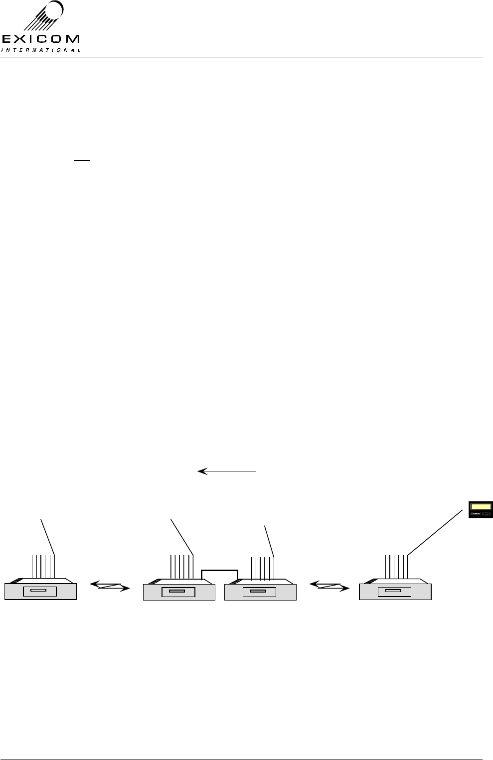
4.1 Two Terminal Link 4-3
4.2 Two Terminal Link with Repeater Terminal 4-3
4.3 Digital Loopback Configurations 4-11
4.4 Analogue Loopback Configurations 4-13
4.5 End-to-end Bit Error Rate Test 4-15
4.6 Round-trip Bit Error Rate Test 4-15
4.7 Local Interface Bit Error Rate Test 4-15
4.8 Networking EX7100 Terminals 4-18
4.9 Three Terminal Bussed Site 4-18
7.1 EX7100 Terminal with Top Cover Removed 7-2
7.2 VHF EX7100 Terminal with Bottom Cover Removed 7-2
7.3 UHF EX7100 Terminal with Bottom Cover Removed 7-3
7.4 Power Supply Block Diagram 7-4
7.5 Power Supply Fault Diagnostic Tree 7-6
7.6 VHF RF Module Connection Block Diagram 7-9
7.7 VHF Transmitter Module in place within an EX7100 Terminal 7-10
7.8 VHF Transmitter Module Fault Diagnostic Tree 7-12
7.9 UHF RF Module Connection Block Diagram 7-15
7.10 UHF Transmitter Module in place within an EX7100 Terminal 7-16
7.11 UHF Transmitter Module Fault Diagnostic Tree 7-18

EX7100 Technical Manual - List of Figures
©1999 Exicom Technologies (1996) Limited x Issue 2 - May 2001
Page
7.12 Location of Loop Volts adjustment CV101 7-19
7.13 VHF RF Power Amplifier Module in Place within an EX7100 Terminal 7-23
7.14 VHF PA Module Test set-up 7-25
7.15 Bottom Cover Screws for VHF PA Removal 7-26
7.16 Heat Sink Screws for VHF PA Removal 7-26
7.17 UHF RF Power Amplifier Module in Place within an EX7100 Terminal 7-28
7.18 UHF PA Module Test set-up 7-30
7.19 Bottom Cover Screws for UHF PA Removal 7-31
7.20 Heat Sink Screws for UHF PA Removal 7-31
7.21 VHF Receiver Module in Place within Terminal 7-34
7.22 VHF Receiver Module Fault Diagnostic Tree 7-36
7.23 UHF Receiver Module in Place within Terminal 7-40
7.24 UHF Receiver Module Fault Diagnostic Tree 7-42
7.25 Location of Loop Volts adjustment CV101 7-43
7.26 VHF Duplex Filter Adjustment Locations 7-49
7.27 UHF Duplex Filter Adjustment Locations 7-53
7.28 Modem/Controller Block Diagram 7-57
7.29 Modem/Controller in Place within Terminal 7-57
7.30 Modem/Controller Fault Diagnostic Tree 7-59
7.31 Front Panel Block Diagram 7-61
7.32 Front Panel Fault Diagnostic Tree 7-62
7.33 Six Channel Line Interface Connection Block Diagram 7-64
7.34 Subscriber Line Interface in Place within Terminal 7-65
7.35 Exchange Line Interface in Place within Terminal 7-65
7.36 Six Channel Line Interface Fault Diagnostic Tree 7-67
8.1 EX7100 Repeater 8-1

EX7100 Technical Manual - Introduction
©1999 Exicom Technologies (1996) Ltd 1-1 Issue 2 - February 2001
1
Introduction
1.1 General
The EX7100 is a unique digital radio primarily designed to meet the requirements of
customers who require thin route communications, especially in remote and rural
locations, but also in urban areas where digital linking is required. It is an ideal solution
where copper wires are too expensive or difficult to install.
The EX7100 is a 64kbit/s digital radio that operates within a 25kHz RF channel. It has a
number of unique features including:
> On-demand operation,
> Automatic fax and modem data detection (with internal multiplexer installed),
> G.703 and Synchronous Data interface (V.35) to connect to external devices,
> An optional internal six circuit, voice/fax/data, multiplexer,
> High system gain with 2 Watt or 10 Watt power amplifier options,
> Inherent security through proprietary digital encoding,
> Robust design to operate in a variety of environmental conditions.
1.2 Configuration
The EX7100 is a point to point, line of sight system available in two configurations as
detailed below:
1.2.1 64 kbit/s digital “pipe”
The 64kbps single channel configuration uses G.703 and/or synchronous data interfaces
(V.35), for connection to external OEM multiplexers, bridges, routers, LAN’s, etc. The
actual transmitted bit rate including system overheads is 68 kbit/s, allowing a full 64 kbit/s
for the user.
This congifuration is also used to provide a full duplex repeater option, based on two
terminals back-to-back at G.703 interface. A repeater enables the user to greatly increase
the distance between the end terminals

EX7100 Technical Manual - Introduction
©1999 Exicom Technologies (1996) Ltd 1-2 Issue 2 - February 2001
1.2.2 Six low bit rate voice/fax/data channels
With the addition of an internal multiplexer/line interface card the EX7100 provides six,
low bit rate, voice/fax/data channels.
This option is designed to replicate six individual standard wireline telephone circuits and
caters for both 2-wire and 4-wire + E&M (with additional card) telephone operation. Line
drivers and ringers are integral to the card, allowing telephone equipment to be situated
up to 5 kilometres from the terminal when used with external lightning protection.
Most equipment normally connected to telephone lines may be connected to each
channel of the EX7100, including payphone (12/16 kHz meter pulse or line reversal),
electronic funds transfer terminals, G3 fax and data traffic at up to 9600bps.
Note that provision of voice/fax data traffic requires external telephone modems at each
location. Modem/Fax data rate is limited to 9600bps.
The six-channel version of the EX7100 is available in two configurations:
Exchange Terminal
Provides connection for six telephone circuits (either 2-wire or 4-wire +E&M) from the
PSTN. Using two exchange terminals, the link may be configured in software for Point-to-
Point Data terminal operation, providing six 9600bps data channels with 4-wire + E&M
interface.
Subscriber Terminal:
Provides connection for Subscriber equipment (2-wire), such as telephones, facsimile,
modem, etc.
Note: The telephone interface circuit boards within these terminals are specific to each
terminal type, i.e. an Exchange terminal cannot be linked as a Subscriber terminal,
or vice versa.

EX7100 Technical Manual - Introduction
©1999 Exicom Technologies (1996) Ltd 1-3 Issue 2 - February 2001
1.3 About this Manual
This Manual contains all the information necessary to enable installation and configuration
of an EX7100 as well as module and fault diagnosis information.
1.4 Terminology
The following terms and abbreviations are used throughout this manual:
BER Bit Error Rate,
BERT Bit Error Rate Test,
DSP Digital Signal Processing,
ESN Electronic Serial Number,
LCD Liquid Crystal Display
LED Light Emitting Diode,
LMS Link Management System,
LTF Line Terminating Frame,
MDF Main Distribution Frame,
PA Power Amplifier
POTS Plain Old Telephone System
PSTN Public Switched Telephone Network
PSU Power Supply Unit,
RSSI Receive Signal Strength Indication,
TCXO Temperature Controlled Crystal Oscillator,
VSWR Voltage Standing Wave Ratio.
This manual refers to “Exchange Terminal” and “Subscriber Terminal” however the
installation instructions apply equally to non-telephone, or Data, systems.

EX7100 Technical Manual - Introduction
©1999 Exicom Technologies (1996) Ltd 1-4 Issue 2 - February 2001
1.5 EX7100 Specifications
1.5.1 System Parameters
Frequency Bands (MHz) 138-174, 400-520
(Other bands to follow) 240-270, 335-400, 800-900, 1400
RF Frequency Stability ± 1.5 ppm
Available Digital Bandwidth 64 kbit/s
Channel Data Rate 68 kbit/s
RF Bandwidth 25kHz
Digital Interface G.703 or V.35 synchronous
Duplexer VHF: Internal Notch Type
UHF: External Notch Type + Band Pass
Frequency Selection Synthesiser in 5.0 or 6.25kHz steps
Channel Selection Via front panel LCD or external terminal
Maximum Transmitter power @
duplexer output (PEP) UHF > +31 to +40 dBm (1.25 to 10 W) variable
> +24 to +33 dBm (0.25 to 2 W) variable
VHF > +31 to +40 dBm (1.25 to 10W) variable
> +24 to +30 dBm (0.25 to 1 W) variable
Duty Cycle 100% @ 60 °C ambient, < 3000 feet AMSL
Emission Designator 18K4D1WET
Receive Sensitivity 10-3 BER < -105 dBm (<1.3 µV) @ Rx input
1.5.2 Power, Mechanical and Environmental
Ambient Operating Temperature -10 °C to +60 °C
Humidity up to 95% relative humidity, 0 °C to +45 °C,
non-condensing
Size of basic system (H x W x D) VHF: (3U) 135 mm x 483 mm x 425mm1
UHF: (4U) 175 mm x 483 mm x 425 mm1
Weight Approx. 15 kg
Physical Mounting Rack Mount
Line Lightning Protection Secondary Lightning Protection
1 425mm depth dimension measured from front panel handle to end of rear panel bracket. Additional depth allowance
may be required to cater for connecting cables etc.
EX7100 Technical Manual - Introduction
©1999 Exicom Technologies (1996) Ltd 1-5 Issue 2 - February 2001
Power Supply1 10.8 - 30 VDC and 30 - 60 VDC, positive or
negative earth for 12/24/48 VDC power
systems
Power Consumption Standby, 64 kbit/s configuration 35 W
Standby, 6 Ch. configuration 40 W
Tx 10 Watt, 64 kbit/s configuration
Typical 65 W
Maximum 100 W
Tx 10 Watt, 6 Ch. Configuration2
Typical 85 W
Maximum 120 W
Tx 2 Watt, 64 kbit/s configuration
Tx 2 Watt, 6 Ch. configuration2
(2 W figures above TO BE ADVISED)
1.5.3 Multi-channel Voice and Data Multiplexer
Purpose For data and low bit rate voice options
Integral Multiplexer Interface Proprietary
Number of Channels used Up to six low bit rate voice/data/fax
Exchange/Subscriber Line
Connections Via 50-way CHAMP connector
Voice Quality Near toll quality - MOS3 = 3.9
(64 kbit/s PCM MOS = 4.2, 32 kbit/s ADPCM
MOS = 3.8)
Voice Compression MP-MLQ @ 6.3 kbit/s (ITU-T G723.1)
Audio Frequency Response 300 to 3400 Hz typical
Line Interfaces 2-wire, 600Ω/900Ω/complex, 4-wire + E&M
(optional)
Telephone Interface (2-Wire) 2-wire, 600Ω/900Ω/complex, maximum DC
loop resistance 1500Ω, 50 V DC supply
Rx/Tx Line Levels 2 Wire
4 Wire
-15 dBm to +3 dBm
-15 dBm to +3 dBm or –11 dBm to +7 dBm
Line Drive Current 25 or 45 mA selectable
Payphone Interface 12/16 kHz meter pulse and line reversal
Fax and data detection
Fax Speed
Data Speed
Automatic
G3 up to 9.6 kbit/s
Up to 9.6 kbit/s with telephone modems
1 Refer to Section 2, page 2-6 for IMPORTANT WARNINGS re the power supply
2 6 Channel Tx power consumption is maximum with 6 channels operational with 25 mA loop current and no ringing
3 MOS = Mean Opinion Score as defined by ITU-T Rec. P80 and tested by AT&T Study Group 15

EX7100 Technical Manual - Introduction
©1999 Exicom Technologies (1996) Ltd 1-6 Issue 2 - February 2001
1.5.4 Data Channel
Data Interfaces G.703 or V.35 synchronous
Data Rate 64 kbit/s
Connections G.703 - 75 Ω
ΩΩ
Ω
G.703 - 120 Ω
ΩΩ
Ω
Synch. Data
BNC Connectors
DB15 Connector
DB15 Connector to standard V.35 connectors
on extender cable1
1.5.5 System Management
Basic Front Panel Metering LCD digital with bar graph and test points for
connection of external voltmeter
Configuration Menu driven 16x2 LCD with six button control
or via RS485 connection to external PC
System management Standard Proprietary
Inter-site Communications RS485 communications with daisy-chain
capability
Communications and Signalling
data channel 1000 bit/s (not user accessible)
Monitoring of site security or other
alarms Six I/O Ports
Channel Selection Via front panel LCD or external terminal
System Management Functions
• BER alarm set 10-3 to 10-5
adjustable • Loopback on each line (6
channel)
• Repeater mode • 64 kbit/s loopback, local/remote
• Set link active excess alarm time • Set individual Receiver and
Transmitter RF frequencies
• Adjust transmit power level • Antenna alignment mode
• Audio line levels
Alarms
• BER set 10-3 to 10-5 adjustable • Low input voltage
• Low receive signal level • Synth lock fail
• Link up time • External alarms
• Tx high VSWR and low power • Lost modem lock
• Internal voltage rail fault • Link fail alarm
• Over Temperature (UHF 10 W) •
Digital and Analogue Meter Tests and Bar Graph
• Receive signal levels • DC input voltage
• Current consumption • Internal voltage rails
• Tx Heatsink temperature
1 DB15 connector has a proprietary pin-out, refer to Appendix A sections A.3 and A.4 for details

EX7100 Technical Manual - Introduction
©1999 Exicom Technologies (1996) Ltd 1-7 Issue 2 - February 2001
1.6 System Planning
Digital Radio link planning is a complex procedure requiring a study of each site and the
path between each site. Exicom Technologies is able to assist in system planning if this is
required.
Specialist software packages are used by Radio System Engineers to determine path
losses and sources of interfering signals that may affect the reliability of the radio link.
(Unlike an FM signal, a digital radio signal is susceptible to interference and fades, similar
to those found on television broadcast systems)
The EX7100 is capable, under ideal circumstances, of providing communications over
paths of more than 50 kilometres.
However, the following considerations must be taken into account, which will assist in
determining the maximum link distance and system reliability:
> Operating frequencies
> Free Space loss
> Terrain effects: Absorption and Reflection losses
> Antenna gain and position
> Cable losses
> Transmit power
> Receiver sensitivity
> Required fade margin
Further to these considerations, the system designer must be aware of factors at each
site, which may affect the reliability of the radio link. These factors include:
> Access to a reliable power source.
> Antenna height.
> Access to a suitable grounding system.
> Lightning and surge protection
> Other radiating and receiving systems using the site

EX7100 Technical Manual - Introduction
©1999 Exicom Technologies (1996) Ltd 1-8 Issue 2 - February 2001
This page intentionally left blank
EX7100 Technical Manual - Introduction
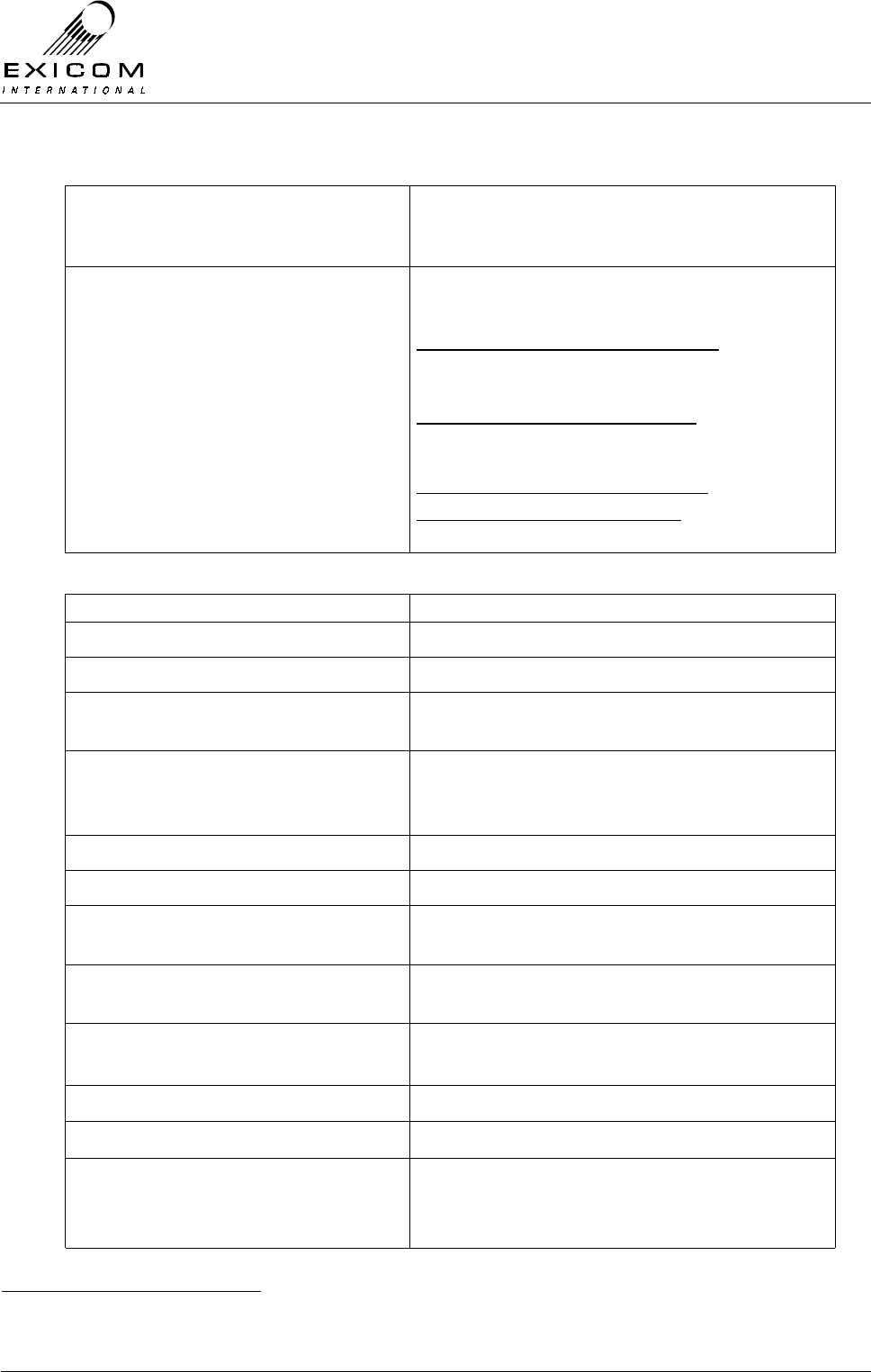
©1999 Exicom Technologies (1996) Ltd 1-9 Issue 2 - February 2001
1.00E-07
1.00E-06
1.00E-05
1.00E-04
1.00E-03
1.00E-02
-108 -107 -106 -105 -104 -103 -102 -101 -100 -99 -98 -97 -96 -95
Receive level (dBm)
BER
-10 to +45 C
-30 to +60 C
VHF/UHF EX7100 at
'nominal' operating
temp range
VHF/UHF EX7100 at
'extreme' operating
temp range
Figure 1.1: Typical BER curve

EX7100 Technical Manual - Introduction
©1999 Exicom Technologies (1996) Ltd 1-10 Issue 2 - February 2001
This page intentionally left blank

EX7100 Technical Manual - Installation of Antenna and Equipment
©1999 Exicom Technologies (1996) Ltd 2-1 Issue 2 - February 2001
2
Installation of Antenna and Equipment
2.1 General
Although EX7100 Radio Link terminals can be installed in any order, the following
sequence should be followed to ensure that minimum time is spent on installation.
> Install Exchange antenna (Section 2.3),
> Mount the Exchange terminal (Sections 2.4 and 2.5),
> Connect power, antenna and interface cables to the Exchange terminal (Section 2.6),
> Configure and test Exchange terminal (Section 3),
> Repeat the above steps for the installation of the Subscriber antenna, Subscriber
terminal and cabling (Sections 2.3 to 2.6 inclusive and Section 3),
> Final antenna alignment at Subscriber site (Section 2.11),
> Final antenna alignment at Exchange site (Section 2.11).
> Establish a test link to confirm operation of system (Sections 4.3.1 and 4.3.2),
Note: Ensure that the correct terminal is dispatched to the appropriate site (Terminal
information can be found on a label on the side of the packing box).
2.2 Antenna Sites
Antenna sites for the EX7100 installation should have been chosen as part of the system
planning process (Refer to Section 1.6). If they have not been selected, contact your
Exicom International Supplier.
Radio path planning is a highly technical procedure and should only be performed by a
qualified person.
WARNING
THIS EQUIPMENT MUST ONLY BE INSTALLED AND
MAINTAINED BY SERVICE PERSONNEL
EX7100 Technical Manual - Installation of Antenna and Equipment
©1999 Exicom Technologies (1996) Ltd 2-2 Issue 2 - February 2001
2.3 Mounting the Antenna
The antenna should be mounted high enough so that it is in "line-of-sight" with the
antenna at the other radio site (antenna height may have been determined during system
planning). The antenna should be placed at least 10 metres (VHF) or 3.5 metres (UHF)
from any metallic or conductive objects to avoid possible impaired operation of the
EX7100 link and fastened securely to protect against the effects of strong winds.
When mounting the antenna, ensure it is pointing in the correct direction with the correct
polarisation. Final adjustments to the antenna direction are made after both terminals are
installed. Refer to Section 2.11 "Final Antenna Alignment".
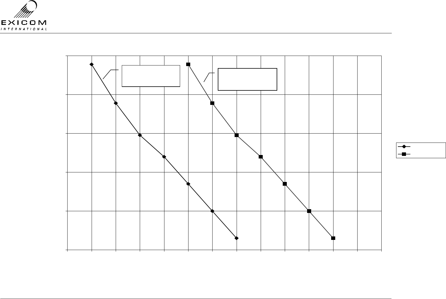
2.3.1 Antenna Polarisation
The site plan should include details of antenna polarisation. If it doesn't, use the following
information as a guide:
The antenna may be mounted with either vertical or horizontal polarisation. Figure 2.1
shows an antenna mounted with vertical polarisation (top) and horizontal polarisation
(bottom). In general, either polarisation can be used although each antenna must have
identical polarisation.
Note: Vertical antenna polarisation is preferred if the radio link is to be used over a body
of water such as a lake or sea.
Figure 2.1: Antenna Polarisation
EX7100 Technical Manual - Installation of Antenna and Equipment
©1999 Exicom Technologies (1996) Ltd 2-3 Issue 2 - February 2001
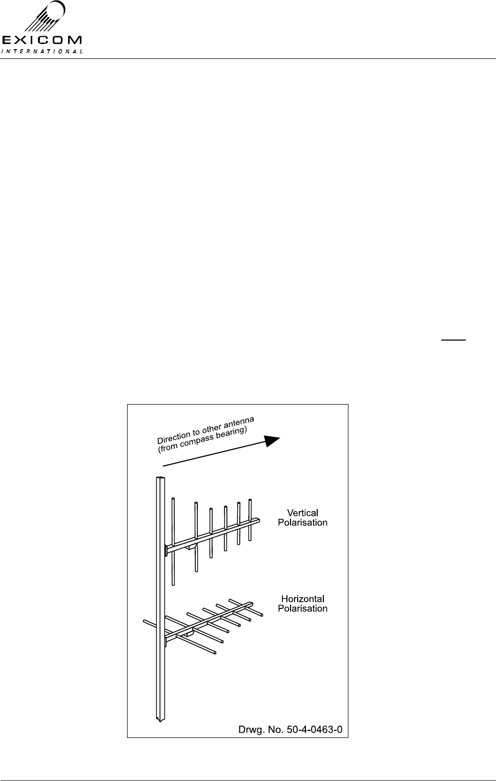
2.3.2 Antenna Direction
The site plan should include details of antenna direction. If it doesn't, use the following
information as a guide:
Refer to a map with the antenna sites marked. The antennas must point towards each
other in a straight line for the link to operate effectively. Take a compass bearing of each
antenna as shown in Figure 2.2. This is the direction the antenna should point towards
when mounted.
Figure 2.2: Antenna Direction
2.3.3 Antenna Cable Grounding Kits
To assist with lightning protection, coaxial cable grounding kits should be used at each
site. Grounding of the cable is recommended at the tower top, tower bottom and at the
entrance to the equipment shelter.
A range of grounding kits are available. Contact your Exicom International Supplier for
details.

EX7100 Technical Manual - Installation of Antenna and Equipment
©1999 Exicom Technologies (1996) Ltd 2-4 Issue 2 - February 2001
2.4 Positioning the EX7100 Terminal
Before deciding on the position of the terminal, consider the following:
> The antenna coaxial cable should be as short as practical to minimise transmission
losses,
> The EX7100 requires good ventilation to allow generated heat to escape. Although
the maximum temperature environment for the EX7100 is +60°C, lower temperatures
will assist with trouble-free operation, as is the case with most electronic equipment,
Always allow a gap of at least 2U1 (89mm) above/below the terminal and any other
equipment,
> The EX7100 should be mounted close to a source of power, telephone wires (if
required) and the antenna cable. Note: Ensure that sufficient room for any cables
(including adequate bend radius etc) is present prior to positioning the terminal2
> Access to a good earth is essential (separate to mains earth) refer to Section 2.8,
> It may be necessary during the installation process (or subsequent servicing) to
access the rear panel of the terminal. Sufficient room should therefore be provided
around the terminal to allow access to any connections (such as the RS485 port that
may be used for PC control during testing and set-up).
1 One U = 44.5 mm or 1 ¾ inch
2 Terminal depth of 425mm is measured from front panel handle to end of rear panel bracket. Additional
depth allowance may be required to cater for connecting cables etc.
WARNING
Ensure that the equipment racks are stable and capable o
f
supporting the weight of the EX7100 terminal before
equipment installation. Note that unsecured racks may tip over,
causing damage to equipment or personal injury

EX7100 Technical Manual - Installation of Antenna and Equipment
©1999 Exicom Technologies (1996) Ltd 2-5 Issue 2 - February 2001
2.5 Mounting the Terminal in the Rack
The EX7100 is compatible with the industry standard 19" rack system and occupies 3U1
(VHF) or 4U (UHF) of vertical space.
> Attach the handles to the EX7100 front panel using the handle kit supplied.
> Attach the front panel to the radio terminal using the six screws supplied.
> Mount the terminal to the rack using the four front panel mounting points. Due to the
weight of the EX7100 terminal (approx. 15 kg), it is highly recommended that the
terminal be supported with the use of angled side rails. These rails are commonly
found in 19” racking systems (but are not included with EX7100 terminals).
> Ensure that the terminal’s chassis ground is connected to the equipment rack’s
ground via the chassis earth screw terminal. (Refer to Section 2.8)
2.6 Cable Connections
2.6.1 General
Cable configuration is dependent on the variant of the terminal being installed, i.e. Data,
Exchange, or Subscriber. (Refer to section 1.2)
However, there are some generic connections required, regardless of variant type:
> The RF connection,
> The power supply connection,
> The earth connection.
RF Connection
VHF system: The VHF EX7100 uses an internal duplexer Connect the antenna’s coaxial
cable to the N-type socket marked ‘ANT’.
UHF system: The UHF EX7100 uses an externally mounted duplexer. Connect the
antenna’s coaxial cable to the N-type antenna socket on the lid of the terminal. If the
duplexer leads have been disconnected from RF connectors on the rear panel, it is
important they are reconnected correctly.
The connector marked thus: is connected to the Transmitter. (RF out).
The connector marked thus: is connected to the Receiver. (RF in).
1 One U = 44.5 mm or 1 ¾ inch
EX7100 Technical Manual - Installation of Antenna and Equipment
©1999 Exicom Technologies (1996) Ltd 2-6 Issue 2 - February 2001
If the terminal’s transmitter frequency is higher than it’s receiver frequency, the RF output
connector should be connected to the high-pass side of the duplexer.
If the terminal’s transmitter frequency is lower than it’s receiver frequency, the RF output
connector should be connected to the low-pass side of the duplexer.
Figure 2.3 below shows the RF connections for a UHF duplexer.
Figure 2.3: UHF Duplexer Connections
A suitable lightning arrestor must be installed at all
times in the coax cable between the EX7100 terminal
and the antenna.
BRBP
Band Reject
Band Pass
Filter
(HPF)
BPBR
Band Pass
Band Reject
Filter
(LPF)
4 Cavity Duplex filter
High Low
low pass
adjustment
High pass
adjustment
Tx or Rx Tx or RxAntenna
1234567
A B C D E F G H I J

EX7100 Technical Manual - Installation of Antenna and Equipment
©1999 Exicom Technologies (1996) Ltd 2-7 Issue 2 - February 2001
The arrester must have a direct earth connection and must be mounted at either the base
of the antenna mast or where the coax cable enters the building. For further detail on
mounting the antenna, refer to the documentation that accompanies it.
Note: Ensure that any coaxial connectors exposed to the weather are adequately
protected with suitable weatherproof tape that completely seals the connector from
moisture.
DC Power Input
The EX7100 terminal is supplied with two variants of internal power supply:
> 10.8 VDC – 30 VDC Input
> 30 VDC – 60 VDC Input
If the terminal is to be powered by an existing DC power supply, ensure the voltage
supplied by the power supply system falls within one of the ranges detailed above.
Note: The terminal has a built-in sensing circuit and will not operate if the supply voltage
or polarity is incorrect.
DC Input cabling should be capable of carrying 15 Amps @ 12V, 7.5 Amps @ 24V, and
4.0 Amps @ 48V. The maximum permitted voltage drop in the cable is 200mV.
Note: The terminal requires an external fuse (not supplied) within the DC Input cabling.
Fuse ratings vary depending on the nominal DC input voltage used:
Nominal DC Input Voltage Fuse Rating
12 V DC 60 Amp HRC type
24 V DC 30 Amp HRC type
48 V DC 20 Amp HRC type
HRC fuses should be used with a minimum current breaking capacity of 5000
Amps (as lead acid batteries are likely to be used to back up the DC supply)
NOTICE
Supply power to this equipment must be provided via an approved
power supply whose output voltages are in accordance with the
Safety Extra Low Voltages (SELV) limits as specified in IEC950.
Failure to operate this equipment with this type of power supply
would void safety approvals

EX7100 Technical Manual - Installation of Antenna and Equipment
©1999 Exicom Technologies (1996) Ltd 2-8 Issue 2 - February 2001
Connect the power supply cable to the 3-way connector marked ‘- GND +’. The DC input
lines on this connector are floating and have no power connection to the chassis ground
(neither the positive nor the negative terminal is connected to the EX7100 chassis). This
enables the EX7100 to be powered from either a positive or negative ground supply.
The centre terminal of the DC input connector is connected to the EX7100’s chassis and
may be strapped to the side of the DC input that is at station ground potential.
2.7 Terminal Type Specific Connections
The EX7100 is supplied as one of three types, Data, Exchange, or Subscriber. (Refer to
section 1.2). The interface connections to each terminal type are different.
Connection details for the three terminal types are as follows:
2.7.1 Digital Data Terminal Connections
The EX7100 provides both synchronous Data, e.g. V.35 and CCITT G.703 co-directional,
digital interfaces. The terminal automatically detects the presence of a digital interface
card.
Selection of the interface required is made in software using the front panel keypad. Refer
to Section 3.4.1 for configuration details.
Synchronous Data V.35
Once selected, the synchronous Data interface is made available on the DB15 connector
labelled ‘SYNC DATA’ on the terminal’s rear panel. Detailed pin-out information can be
found in Appendix A.4.
Various adapter cables are available to cater for V.35, RS-232 conversion. Contact your
Exicom International Supplier for details.
G.703
Once selected, the G.703 interface is made available on the DB15 connector labelled
‘G.703’ (for detailed pin-out information refer to Appendix A.3) and also on the pair of
BNC connectors labelled ‘G.703’, on the terminal’s rear panel.
The DB15 connector provides a 120 Ohm co-directional interface, whereas the BNC
connectors provide a 75 Ohm co-directional interface. It should be noted that the arrows
alongside the BNC connectors indicate the data flow to and from the terminal.
2.7.2 Exchange Terminal Connections
The EX7100 Exchange terminal allows connection of six 2-wire telephone circuits; six 4-
wire+E&M telephone circuits, or six 4-wire+E&M data circuits (up to 9600bps).
All circuits are connected to the terminal via the 50-way Champ connector, labelled ‘LINE
INTERFACE’, on the terminal’s rear panel. (For detailed pin-out information refer to
Appendix A.6)
The Exchange Terminal may be supplied with a 3 or 10 metre cable that can be plugged
directly into this connector. The other end of this cable should be terminated into the
PSTN’s MDF. Contact your Exicom International Supplier for details.

EX7100 Technical Manual - Installation of Antenna and Equipment
©1999 Exicom Technologies (1996) Ltd 2-9 Issue 2 - February 2001
Note: The EX7100 automatically detects the presence of an Exchange interface card.
The terminal is configured for 2-wire or 4-wire+E&M, in software via the front panel
keypad. Refer to Section 3.4.3 for configuration details.
The Exchange terminal may also be software configured, via the front panel keyboard, as
a point to point Data terminal. Refer to Section 3.4.3 for configuration details.
2.7.3 Subscriber Terminal Connections
The EX7100 Subscriber terminal provides six 2-wire telephone circuits for connection to
equipment such as telephones, payphones, EFT-POS terminals, etc.
These circuits are accessed from the terminal via the 50-way Champ connector, labelled
‘LINE INTERFACE’, on the terminal’s rear panel. (For detailed pin-out information refer to
Appendix A.6)
The Subscriber terminal may be supplied with a 3 or 10 metre cable that can be plugged
directly into this connector. The un-terminated end of the cable may be either wired
directly to the user equipment, to an existing MDF, or to Exicom’s optional Line
Terminating Frame (LTF). Contact your Exicom International Supplier for details
Note: The EX7100 automatically detects the presence of a Subscriber interface card.
The LTF is available with various connector options, as well as optional Primary Lightning
Protection circuitry. Contact your Exicom International Supplier for further details.
2.8 Earthing the Terminal
The provision of a suitable earth for the terminal is the responsibility of the installer. The
EX7100 has a screw terminal on the rear panel to connect the terminal to earth.
This will assist in preventing damage to the terminal from lightning strikes, particularly
strikes to the telephone cables. Protection from strikes to the antenna system may be
provided by fitting the recommended antenna lightning arrester.
For these protective measures to be effective, the system requires a good earth
connection. Mains earth is not adequate, nor is a thin wire or any wire with bends or twists
in it.
The best earth connection is using a suitably heavy wire (e.g. >4 mm2 copper cable)
connected straight to an earthing stake driven into the ground
If this is not possible, connect the earth cable to the equipment rack ground system.
2.9 Other Rear Panel Connections
The EX7100 is fitted with several other rear panel connectors as detailed below. Some of
these connectors will not be used for all applications, however descriptions of their
functions are detailed below.
Note: Detailed pin-out information can be found in Appendix A.
EX7100 Technical Manual - Installation of Antenna and Equipment
©1999 Exicom Technologies (1996) Ltd 2-10 Issue 2 - February 2001
2.9.1 Control
A DB9 connector provides access to the internal RS-485 bus for future expansion of the
EX7100, and for back-to-back repeater connection. This connector will allow system
control of externally mounted interface cards that are yet to be developed. The Control
bus is not user accessible.
2.9.2 LMS
A DB9 connector provides access to the internal RS-485 bus to allow daisy chaining of
multiple terminals and connection to an external Link Management device - ELMS. Refer
Appendix B-2.
2.9.3 I/O
A DB25 connector provides high and low priority alarm outputs, and six input/output
contacts for connection of non-latching externally generated site alarms that are sent
across the radio link when triggered.
Important Note: The I/O port is optically isolated. Details of maximum voltages and
currents are given in Appendix A.5. Failure to comply with this criteria may cause damage
to the I/O port.
External Site Alarms
The EX7100 provides the facility to connect up to six non-latching external alarm contacts
which, when triggered, are sent across the radio link. Alarms may include: Site door
alarm, site fire alarm, or generator fuel low alarm.
When an external alarm contact closes, the alarm is sent across the link, via the
engineering channel, and the corresponding output at all intermediate terminals are
triggered. An external alarm appears on the front panel along with standard alarms.
Figure 2.4: External Alarms
2.9.4 RF
Allows connection to an externally mounted Duplexer, if required. (For example, UHF
Duplexer Type 8045)
EX7100
EXICOM
o o
o o
o o
o
oEX7100EX7100
EXICOM
o o
o o
o o
o
oEX7100
Repeater
RS-485
EX7100
EXICOM
o o
o o
o o
o
oEX7100
EX7100
EXICOM
o o
o o
o o
o
oEX7100
Transmitted
Burglar Alarm
Direction of Alarm
Burglar Alarm
External input 0 goes low
External output 0 goes low
I/O
Receiv ed
Burglar Alarm
External output 0
goes low
I/O
Receiv ed
Burglar Alarm
External output 0
goes low External output 0
goes low
I/O

EX7100 Technical Manual - Installation of Antenna and Equipment
©1999 Exicom Technologies (1996) Ltd 2-11 Issue 2 - February 2001
2.10 Powering up the Terminal
2.10.1 General
Before powering up, ensure that all cables are connected correctly and that there is DC
power to the EX7100 terminal. Pay particular attention to the RF cable assembly,
ensuring all connections are tight.
The EX7100 on/off switch is located on the rear panel.
Note: This switch has an interlocking feature that prohibits accidental switch off. To
toggle the switch on or off you must pull the switch gently forward.
2.10.2 Procedure
Turn on the EX7100 terminal with the on/off switch. The EX7100 will perform an internal
initialisation test, before settling to its idle state.
Figure 2.5: EX7100 Front Panel Display - Initialisation Test
In this idle state, the front panel LCD will display:
Figure 2.6: EX7100 Front Panel Display – Idle State
Note: ‘Exicom EX7100’ is the factory default terminal descriptor. This descriptor can be
any 16 character string, and may be changed at any time (Refer to Section 3.4.1).
If this descriptor was specified at time of order, the display will reflect that. For
example:
Figure 2.7: EX7100 Front Panel Display – Order Specified Terminal Descriptor
If the Operating Mode is configured as ‘100%’ mode, the ‘Tx on’ LED will light and the
system will attempt to establish a link with the remote terminal. This condition will continue
until a link has been established, indicated by the ‘Rx lock’ LED being lit.
If the Operating mode is configured as ‘on-demand’ the terminal will not turn on its
transmitter until a valid request is sent from the relevant user interface, e.g. telephone off-
hook.
initialising
■■■■■■■■■
Exicom EX7100
1 Jan 1210:01
Exchange no 1
1 Jan 1210:01
EX7100 Technical Manual - Installation of Antenna and Equipment
©1999 Exicom Technologies (1996) Ltd 2-12 Issue 2 - February 2001
It is now recommended that you proceed to Section 3 ‘Configuring the Terminal’, to
ensure that the EX7100 terminal has been configured for your specific application.
2.11 Final Antenna Alignment
2.11.1 General
This part of the installation requires two people, or one person with an analogue voltmeter
plugged into the terminals front panel monitoring point. The voltmeter leads need to be
long enough for the installer to view the display while rotating the antenna.
You will also need to refer to Section 3 of this Manual for instructions on using the
EX7100’s front panel.
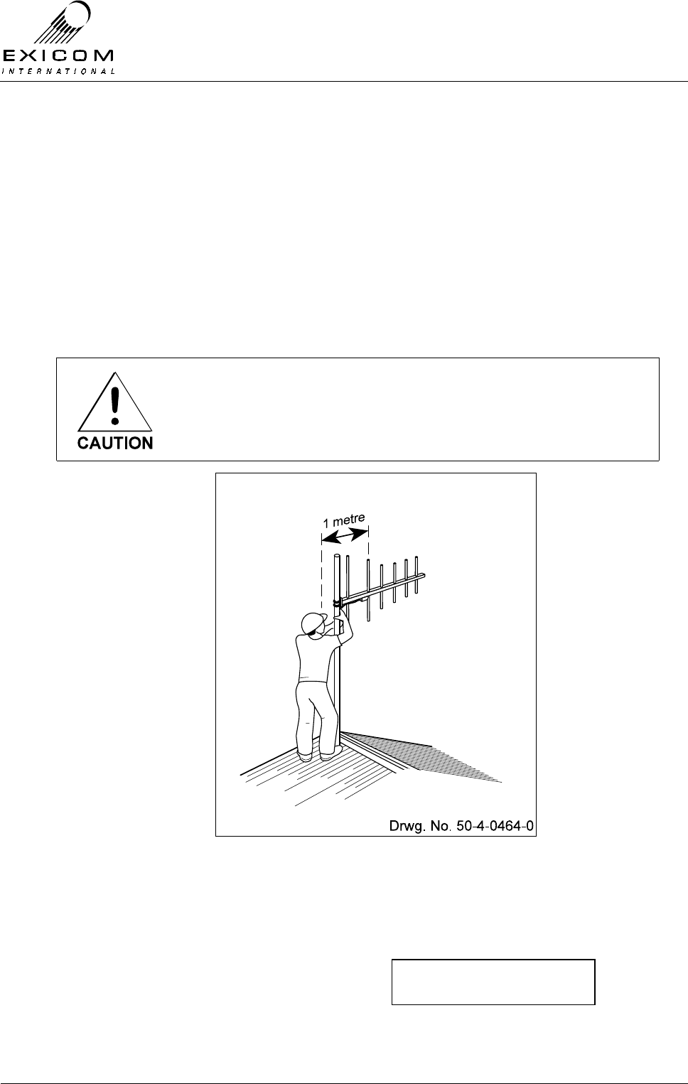
Do not stand in front of the antenna, as electromagnetic radiation
may be hazardous to your health. Leave at least 1 metre between
the installer and the antenna as shown below
Figure 2.8: Antenna Alignment
2.11.2 Alignment Sequence
1) Set up a Test Link by following the
procedure outlined in Section 4.3.1.
2) Use the up and down arrow keys to
make sure the →
→→
→ is next to Antenna
Align and then press ‘Enter’
12345678
→antenna align

EX7100 Technical Manual - Installation of Antenna and Equipment
©1999 Exicom Technologies (1996) Ltd 2-13 Issue 2 - February 2001
3) The local terminal’s transmitter will turn
off (Tx LED will go off), allowing the user
to adjust the antenna safely. The remote
Tx will remain on for up to 60 minutes.
RSSI is now displayed on the screen as
well as on the voltmeter inputs on the
front panel.
4) While one person watches the RSSI
level, the other should move the antenna
direction slightly until the RSSI level is at
its highest. This is the optimum antenna
alignment. Make sure you stand at least
one metre behind the active element
while taking a reading so as not to cause
interference. Tighten the mounting bolts.
(Note: One person can do both tasks if a
voltmeter with long leads is connected to
the jacks on the front panel.
5) Press ‘Escape’. The link will restart and
the menu will return to Antenna Align.
Press ‘Escape’ again then use the up
and down arrows to make sure the →
→→
→ is
next to End Remote Tests and then
press ‘Enter’.
This completes the installation of the terminal.
Repeat this “Final Antenna Alignment” procedure for the other terminal.
RSSI: -90 dbm
■■■■■■■■■■■
Start tests
→end remote tests
RSSI: -95 DBM
■■■■■■■■■

EX7100 Technical Manual - Installation of Antenna and Equipment
©1999 Exicom Technologies (1996) Ltd 2-14 Issue 2 - February 2001
This page intentionally left blank
EX7100 Technical Manual - Configuring the Terminal
©1999 Exicom Technologies (1996) Ltd 3-1 Issue 1 - May 2001
3
Configuring the Terminal
3.1 General
In many cases, the terminal will have been configured in the factory, however it is
recommended that certain operating parameters be checked and corrected as required
before attempting to set-up a link.
The EX7100 is equipped with a powerful configuration, monitoring, and diagnostic, system
that may be accessed using the six-button keypad and LCD on the front panel. The front
panel also has four LED's that indicate the operating status of the terminal, as well as any
alarms being generated by the terminal.
3.2 Using the Keypad
The EX7100 six-button keypad allows the user to scroll through the user interface menu,
and then select, or change, the relevant parameters.
A password is required to allow access to the menu system. This password is ‘1111’, and
cannot be changed. A Second Level password is required to allow amendment of
operating parameters. This password may be changed at any time from the Exicom
default value of ‘1234’. Refer to Section 3.4.1 for details.
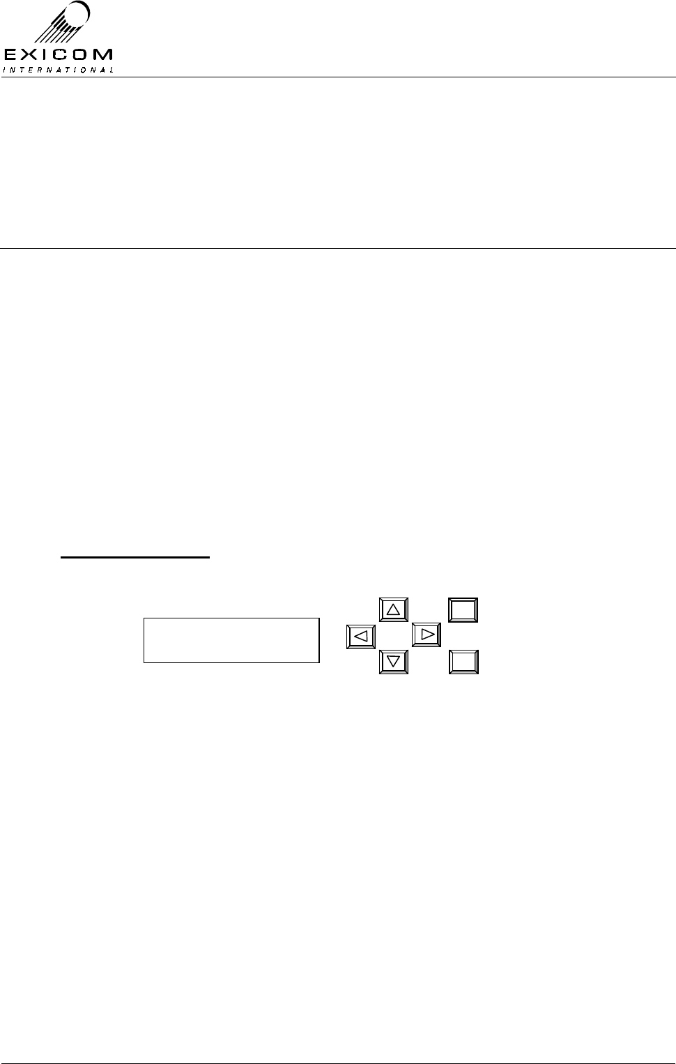
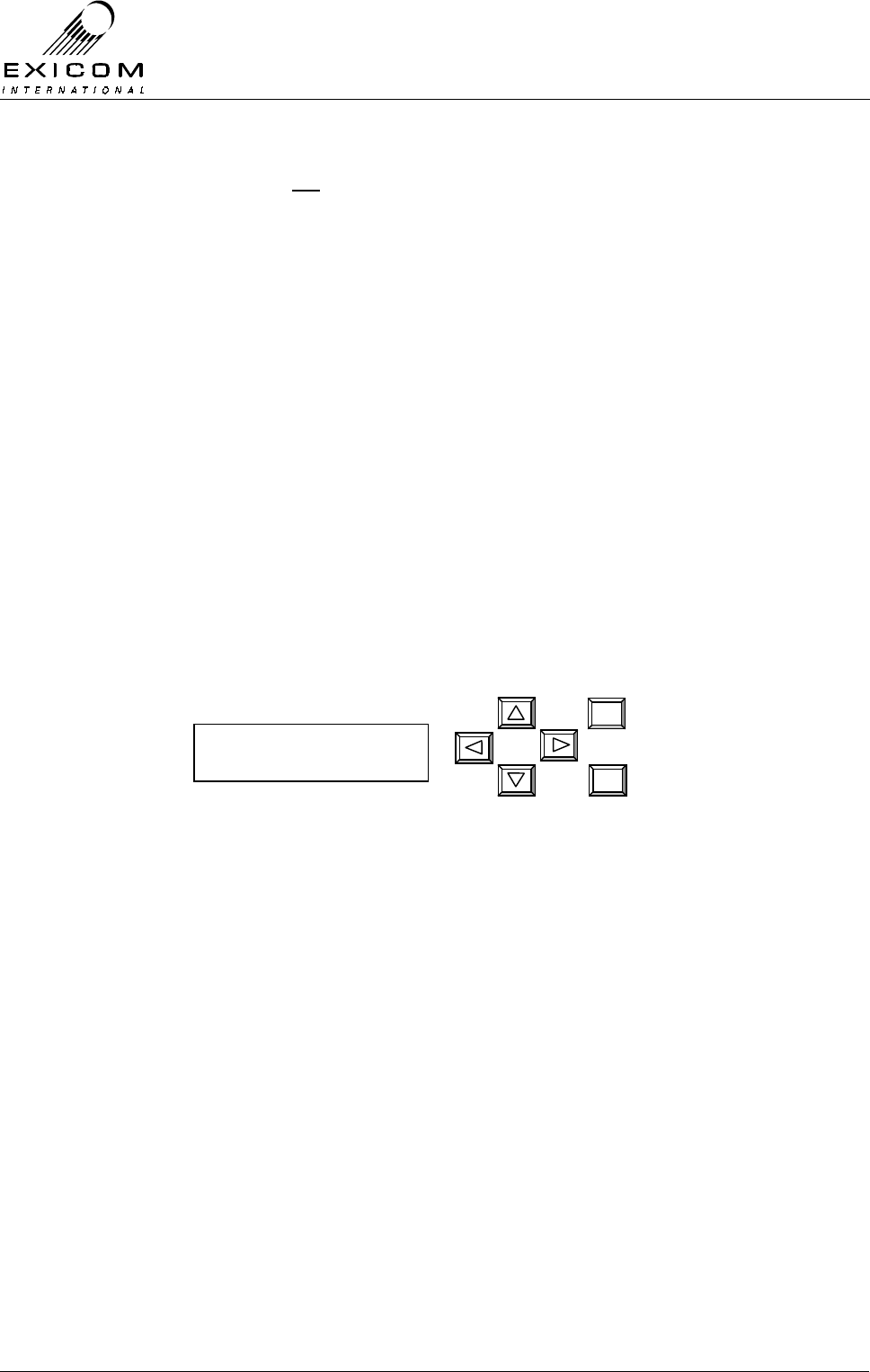
Figure 3.1: EX7100 Front Panel Display and Keypad
Direction Buttons
The four direction buttons provide up and down scrolling, as well as moving the cursor left
and right along any particular line.
Example: To change the default second level password from ‘1234’ to ‘2222’
(Refer to Section 3.4.1 for full details):
> Use the right arrow key to position the ↑
↑↑
↑ under the ‘1’.
> Press the up arrow key once to change the ‘1’ to a 2.
> Press the right arrow key twice to position the ↑
↑↑
↑ under the ‘3’.
> Press the down arrow key once to change the ‘3’ to a 2.
> Press the right arrow key once to position the ↑
↑↑
↑ under the ‘4’.
> Press the down arrow key twice to change the ‘4’ to a 2.
> Press ‘Enter’ to accept changes.
Exicom EX7100
1 Jan 1200.01
EX7100 Technical Manual - Configuring the Terminal
©1999 Exicom Technologies (1996) Ltd 3-2 Issue 1 - May 2001
Note: The user menu is not a continuous loop. Once the cursor reaches the bottom of the
menu, you must use the up arrow to step back up to the top. Similarly, once the
cursor reaches the top of the menu you must use the down arrow to step back
down.
‘Enter’ Key
The ‘Enter’ key operates the same as a computer keyboard ‘Enter’ key. This will accept
any changes you have made to a parameter, or access the next menu level if available.
This will be indicated by a →
→→
→ symbol.
‘Escape’ Key
The ‘Escape’ key enables the user to back out of a menu location.
3.3 The User Interface Menu
The 16x2 digit display lets the user see two lines of the menu at once. As the user scrolls
up or down through the menu, the →
→→
→ symbol will indicate which line will be selected if the
‘Enter’ key is pressed.
When viewing certain parameters, the LCD will give a numerical reading as well as a
graphical display. For example, an RSSI reading may look like this:
Figure 3.2: EX7100 Front Panel Display – RSSI Reading
3.4 Changing Parameters
This section is split into four areas:
Universal Parameters (refer to Section 3.4.1)
This section explains how to check and reconfigure certain operating parameters, which
are generic to all EX7100 terminals, whether Data, Exchange, or Subscriber.
Data Terminal Parameters (refer to Section 3.4.2)
This section explains how to check and reconfigure certain operating parameters, which
are specific to 64kbps Data terminals only.
Exchange Terminal Parameters (refer to Section 3.4.3)
This section explains how to check and reconfigure the operation of certain parameters
that are specific to Exchange terminals only.
Note that an Exchange terminal normally connects to the PSTN or a PABX. When used in
conjunction with a Subscriber terminal the system provides six replacement telephone
circuits.
RSSI: -95 DBM
■■■■■■■

EX7100 Technical Manual - Configuring the Terminal
©1999 Exicom Technologies (1996) Ltd 3-3 Issue 1 - May 2001
Two Exchange terminals may also be configured as a 4-wire Point to Point system. In this
mode, the system provides six, 4-wire trunked audio circuits with E & M wire control
signalling.
Subscriber Terminal Parameters (refer to Section 3.4.4)
This section explains how to check and reconfigure the operation of certain parameters,
which are specific to Subscriber terminals only.
3.4.1 Universal Parameters
Passwords.
EX7100 is protected by two levels of passwording.
The Low Level password is required to access the front panel menu system and is factory
fixed as ‘1111’. This cannot be changed by the user.
The High (or Second) Level password (required to change important operating
parameters) may be changed from the Exicom factory default setting of ‘1234’ to any four-
digit number.
Note 1: If the high level password is changed and the new password subsequently
forgotten, you will need to contact Exicom for a backdoor password.
Note 2: It is possible to disable either/both passwords as detailed below. It
should be noted however, that disabling the passwords will allow any
unauthorised person to change the terminal’s configuration.
Changing the Second Level Password.
1) From idle, press ‘Enter’
You will be asked to enter the password.
Note this is the First Level password
which is factory fixed at ‘1111’
Use the arrow keys to enter ‘1111’, then
press ‘Enter’.
(Note: the up and down arrows increase
or decrease the number above the ↑
↑↑
↑
symbol)
2) Use the up and down arrow keys to make
sure the →
→→
→ is next to Controller.
Press ‘Enter’
3) Use the up and down arrow keys to make
sure the →
→→
→ is next to Passwords.
Press ‘Enter’
4) Use the up and down arrow keys to make
sure the → is next to Change Password.
Press ‘Enter’
Password ∗ ∗ 1 ∗
↑
→Controller
RF PARAMETERS
Set Time / date
→passwords
→change password
disable lo p/word

EX7100 Technical Manual - Configuring the Terminal
©1999 Exicom Technologies (1996) Ltd 3-4 Issue 1 - May 2001
4) You will be asked to enter the old Second
Level password. If this is still set to the
factory default value, use the arrow keys
to enter ‘1234’, then press ‘Enter’
5) You will be asked for the new Second
Level password. Use the arrow keys to
change the old password to the required
new password and press ‘Enter’
6) You will be asked to confirm the new
password. Use the arrow keys to re-enter
the new Password, and press ‘Enter’
7) The new Second Level password is now
set. Press ‘‘Escape’’ until the display
returns to idle.
Disabling the Passwords.
1) From idle, press ‘Enter’
You will be asked to enter the password.
Note this is the First Level password
which is factory fixed at ‘1111’
Use the arrow keys to enter ‘1111’, then
press ‘Enter’.
(Note: the up and down arrows increase
or decrease the number above the ↑
↑↑
↑
symbol)
2) Use the up and down arrow keys to make
sure the →
→→
→ is next to Controller.
Press ‘Enter’
3) Use the up and down arrow keys to make
sure the →
→→
→ is next to Passwords.
Press ‘Enter’
4) Use the up and down arrow keys to make
sure the → is next to ‘Disable Lo Lvl’, or
‘Disable Hi Lvl’.
Press ‘Enter’
5) You will be asked to enter the old Second
Level password. If this is still set to the
factory default value, use the arrow keys
to enter ‘1234’, then press ‘Enter’
6) The password has now been disabled. To
re-enable the password, follow the same
process.
Old p/word: 0* * *
↑
New p/word: 0* * *
↑
Confirm p/w: 0***
↑
Password ∗ ∗ 1 ∗
↑
→Controller
RF PARAMETERS
Set Time / date
→passwords
change password
→Disable lo lvl
Old p/word: 0* * *
↑
EX7100 Technical Manual - Configuring the Terminal
©1999 Exicom Technologies (1996) Ltd 3-5 Issue 1 - May 2001
Changing the Time and Date.
The Time and Date should be changed to reflect local settings. Note that the date field
follows the UK format: DD/MM/YY.
1) From idle, press ‘Enter’
Use the arrow keys to enter the First Level
password ‘1111’ and then press ‘Enter’.
2) Use the up and down arrow keys to make
sure the →
→→
→ is next to Controller.
Press ‘Enter’.
3) Use the up and down arrow keys to make
sure the →
→→
→ is next to Set Time/Date.
Press ‘Enter’
4) The current time and date is displayed. As
in the example at the start of this section,
use the arrow keys to change the time and
date to the required local settings and then
press ‘Enter’
The new time takes effect when the ‘Enter’
key is pressed.
5) Press ‘‘Escape’’ until the display returns to
idle
Operating Mode.
Ensure that this parameter is set to either:
> Terminal 100% (link is continually up),
> Terminal On Demand (link is up only with traffic),
> Repeater 100% (terminal configured as a repeater transmitting continually),
> Repeater On Demand (terminal configured as a repeater transmitting only with
traffic).
1) From idle, press ‘Enter’
Use the arrow keys to enter the First Level
password ‘1111’ and then press ‘Enter’.
2) Use the up and down arrow keys to make
sure the →
→→
→ is next to Controller.
Press ‘Enter’.
3) The screen will read Operating Mode.
Press ‘Enter’
Password ∗ ∗ 1 ∗
↑
Operating mode
→set time/date
1201:01 01/01/98
↑
→Controller
RF PARAMETERS
→operating mode
set Time / date
Password ∗ ∗ 1 ∗
↑
→Controller
rf parameters

EX7100 Technical Manual - Configuring the Terminal
©1999 Exicom Technologies (1996) Ltd 3-6 Issue 1 - May 2001
4) Use the up and down arrow keys to
choose the required operating mode and
then press ‘Enter’.
Note that the current setting is indicated by
an asterisk.
5) Press ‘‘Escape’’ until the display returns to
idle.
Link ID.
The Link ID is the identification number for the link. There are 99 possible numbers from
1-99. (The factory default setting is 01)
Both terminals in the link must have the same Link ID setting. (If a repeater configuration
is used, see Section 8, all terminals must have the same link ID).
1) From idle, press ‘Enter’
Use the arrow keys to enter the First Level
password ‘1111’ and then press ‘Enter’.
2) Use the up and down arrow keys to make
sure the →
→→
→ is next to Controller and then
press ‘Enter’.
3) Use the up and down arrow keys until the
→
→→
→ is next to Change Link ID and then
press ‘Enter’.
4) Use the arrow keys to enter the required
link identification number (0-99)
Note: all terminals in a link must have the
same Link ID (including repeaters).
Press ‘Enter’ to accept changes.
5) Press ‘Escape’ until the display returns to
idle.
Terminal Descriptor.
If required, a 16-character description of the terminal can be set. If changed from the
factory default setting, the terminal descriptor will be displayed on the front panel while the
user interface is idle, and will be displayed instead of the ESN when being accessed from
a remote location.
1) From idle, press ‘Enter’
Use the arrow keys to enter the First Level
password ‘1111’ and then press ‘Enter’.
2) Use the up and down arrow keys to make
sure the →
→→
→ is next to Controller.
Press ‘Enter’.
Change password
→change Link id
Password ∗ ∗ 1 ∗
↑
→Controller
rf parameters
Link id: 01
↑
Password ∗ ∗ 1 ∗
↑
→Controller
rf parameters
→terminal 100%
term on demand

EX7100 Technical Manual - Configuring the Terminal
©1999 Exicom Technologies (1996) Ltd 3-7 Issue 1 - May 2001
3) Use the up and down arrows until the →
→→
→ is
next to Terminal Desc. Press ‘Enter’
4) Use the keypad to set the required
terminal description and then press ‘Enter’.
5) Press ‘Escape’ until the display returns to
idle.
Changing the RF Channel Increment.
The EX7100 provides RF Frequency increments of either 6.25 kHz (Exicom factory default
setting), or 5.0 kHz. Depending on the operating frequencies you require, it may be
necessary to change this setting to the other value.
Example: If your required frequencies are not divisible by 6.25 kHz you will need to set the
channel increments to 5.0 kHz.
The procedure below is particular to a link at idle. If a link is already established, or you
wish to change the channel increment remotely, the ‘Change Frequency’ command must
be used to action the changes. Refer to Section 4.3.3 for details.
1) From idle, press ‘Enter’.
Use the arrow keys to enter the First Level
password ‘1111’ and then press ‘Enter’.
2) Use the up and down arrow keys to make
sure the →
→→
→ is next to RF Parameters.
Press ‘Enter’.
3) Use the up and down arrow keys to make
sure the →
→→
→ is next to Chan Increment.
Press ‘Enter’.
4) An asterisk (*) shows which increment
setting is currently in use. If required, use
the up and down arrow keys to toggle
between the two settings. Press ‘Enter’ to
accept the change.
5) If the current operating frequencies are
incompatible with the new channel
increment, the terminal will display an
error message. The operating frequencies
will need to be adjusted as required to suit.
6) Press ‘Escape’ until the display returns to
idle.
→chan increment
Tx frequency
Password ∗ ∗ 1 ∗
↑
Controller
→RF PARAMETERS
Change link ID
→terminal desc
Exicom ex7100
↑
Error: tx,rx not
On 25khz step
→ 5 khz
* 6.25 khz

EX7100 Technical Manual - Configuring the Terminal
©1999 Exicom Technologies (1996) Ltd 3-8 Issue 1 - May 2001
Changing the Local Transmitter Frequency.
Ensure the Transmitter is set to operate on the required frequency.
Notes:
- This procedure is specific to a local transmitter. To change the frequency of a
remote transmitter refer to Section 4.3.3.
- The EX7100’s front panel tuning range is limited. If a frequency change of more
than 100kHz is required, it will be necessary to manually retune some parts of the
RF Section of the radio. Transmitter module re-tuning instructions are detailed in
Sections 7.3.3 (VHF) and 7.4.3 (UHF). Duplexer module re-tuning instructions are
given in Sections 7.9.3 (VHF) and 7.10.3 (UHF).
In addition, it may be necessary to replace the Duplexer module if a large change
in frequency is required. Refer Section 7.9.4 (VHF) and 7.10.5 (UHF).
Reserved Frequencies
- There are a number of internationally agreed frequencies that have been reserved
exclusively for Distress and Safety Communications.
It is therefore necessary to prevent transmission on the reserved frequencies (as
well as the frequencies one channel either side of the reserved frequencies)
Affected VHF frequencies:
156.525 MHz (± 5 or 6.25 kHz) & 156.800 MHz (± 5 or 6.25 kHz)
Affected UHF frequency:
406.000 MHz (± 5 or 6.25 kHz)
It is not possible to enter the above frequencies during the Tx frequency change
procedure outlined below (note that this only affects the Tx frequency procedure,
the Rx frequency procedure will allow selection of the frequencies but the
corresponding transmitter cannot be set)
1) The local transmitter must not be
transmitting. Setting the terminal to “On-
demand” operating mode will ensure the
transmitter is idle as long as there is no
data traffic.
From idle, press ‘Enter’
Use the arrow keys to enter the First Level
password ‘1111’ and then press ‘Enter’.
2) Use the up and down arrow keys to make
sure the → is next to Controller.
Press ‘Enter’.
Password ∗ ∗ 1 ∗
↑
→Controller
rf parameters

EX7100 Technical Manual - Configuring the Terminal
©1999 Exicom Technologies (1996) Ltd 3-9 Issue 1 - May 2001
3) Use the up and down arrow keys to make
sure the → is next to Operating mode.
Press ‘Enter’.
4) Use the up and down arrow keys to make
sure the → is next to Term On Demand.
Press ‘Enter’. (The Tx On LED will
extinguish after 10 seconds).
5) Press ‘Escape’ to return to the main menu.
Select RF parameters and press ‘Enter’.
6) Use the up and down arrow keys to make
sure the →
→→
→ is next to Tx Frequency.
Press ‘Enter’
7) The current frequency setting is displayed.
Press ‘Enter’ to change the frequency.
8) You will be asked for the Second Level
password. Exicom’s factory default is
‘1234’. If the default password does not
give access, see your System Engineer as
the password may have been changed
(refer to Section 3.4.1 for details).
9) The current frequency is displayed. Using
the arrow keys, change the frequency to
the required setting. Press ‘Enter’
(Note: When the cursor is under the least
significant digit, the frequency will
increase/decrease by the channel
spacing).
The new frequency has now been set.
Press ‘Escape’ until the main menu is
displayed.
10) If required, repeat steps 3 and 4 to return
the terminal to 100% operation.
Press ‘Escape’ until the menu returns to
idle.
chan increment
→tx frequency
Tx: 150.01275 mhz
→change Freq
Password 1 ∗ ∗ ∗
↑
Tx: 150.01275 mhz
↑
→Operating Mode
SET TIME/date
Terminal 100%
→Term on demand
Controller
→RF parameters
EX7100 Technical Manual - Configuring the Terminal
©1999 Exicom Technologies (1996) Ltd 3-10 Issue 1 - May 2001
Changing the Local Receiver Frequency.
Ensure the Receiver is set to operate on the required frequency.
Notes:
- This procedure is specific to terminals in their idle state. To change the Rx
frequency while a link is established, see 4.3.3.
- The EX7100’s front panel tuning range is limited. If a frequency change of more
than 100kHz is required, it will be necessary to manually retune some parts of the
RF Section of the radio. Receiver module re-tuning instructions are detailed in
Sections 7.7.3 (VHF) and 7.8.3 (UHF). Duplexer module re-tuning instructions are
given in Sections 7.9.3 (VHF) and 7.10.3 (UHF).
In addition, it may be necessary to replace the Duplexer module if a large change
in frequency is required. Refer Section 7.9.4 (VHF) and 7.10.5 (UHF).
1) From idle, press ‘Enter’
Use the arrow keys to enter the First Level
password ‘1111’ and then press ‘Enter’.
2) Use the up and down arrow keys to make
sure the →
→→
→ is next to RF Parameters.
Press ‘Enter’
3) Use the up and down arrow keys to make
sure the →
→→
→ is next to Rx Frequency.
Press ‘Enter’
4) The current frequency setting is displayed.
Press ‘Enter’ to change the frequency.
5) You will be asked for the Second Level
password. Exicom’s factory default is
‘1234’. If the default password does not
give access, see your System Engineer as
the password may have been changed
(refer to Section 3.4.1 for details).
6) The current frequency is displayed. Using
the arrow keys, change the frequency to
the required setting. Press ‘Enter’
(Note: When the cursor is under the least
significant digit, the frequency will
increment/decrement by the channel
spacing).
7) Press ‘Escape’ until the menu returns to
idle. The frequency change is now
complete.
Tx frequency
→rx frequency
rx 155.01275 mhz
↑
rx 155.01275 mhz
→change freq
Controller
→rf parameters
Password ∗ ∗ 1 ∗
↑
Password 1 ∗ ∗ ∗
↑
EX7100 Technical Manual - Configuring the Terminal
©1999 Exicom Technologies (1996) Ltd 3-11 Issue 1 - May 2001
Transmitter RF Power Level.
Ensure the transmitter power level is set as required. The power level is selectable in 3dB
steps (0.25W, 0.5W, 1W, and 2W for a 2Watt system, and 1.25W, 2.5W, 5W, and 10W for
a 10Watt system).
1) From idle, press ‘Enter’.
Use the arrow keys to enter the First Level
password ‘1111’ and then press ‘Enter’.
2) Use the up and down arrows until the →
→→
→ is
next to RF Parameters and then press
‘Enter’.
3) Use the up and down arrows until the →
→→
→ is
next to Tx Power and then press ‘Enter’.
4) The current Tx Power will be displayed.
Press the down key followed by ‘Enter’ to
change the power level.
8) You will be asked for the Second Level
password. Exicom’s factory default is
‘1234’. If the default password does not
give access, see your System Engineer as
the password may have been changed
(refer to Section 3.4.1 for details).
6) The new setting is now in effect.
Press ‘Escape’ until the display returns to
idle.
Interface Type.
Check that the terminal is set for either, G.703 (Codir or Contra), Synchronous Data,
Exchange, or Subscriber as required for connection to your external equipment. This may
be checked on the Framer menu location.
1) From idle, press ‘Enter’
Use the arrow keys to enter the First Level
password ‘1111’ and then press ‘Enter’.
2) Use the up and down arrows until the →
→→
→ is
next to Framer and then press ‘Enter’
3) Use the up and down arrow keys to make
sure the → is next to Interface and press
‘Enter.’
→Rf parameters
framer
rssi
→Tx power
Tx pwr: 2.5 W
→set rf level
Password ∗ 1 ∗ ∗
↑
Rf parameters
→framer
Password ∗ ∗ 1 ∗
↑
→interface
Tx Data Clock
Password 1 ∗ ∗ ∗
↑

EX7100 Technical Manual - Configuring the Terminal
©1999 Exicom Technologies (1996) Ltd 3-12 Issue 1 - May 2001
4) Use the up and down arrow keys to make
sure the → is next to the required
interface type. Press ‘Enter’ to accept.
Note that the currently selected setting is
indicated by an asterisk.
5) Press ‘‘Escape’’ until the display returns to
idle.
3.4.2 Data Terminal Parameters
Transmit Data Clock Synchronisation.
For each digital interface, the 64kbps transmitted data may be synchronised to one of
three options. These are:
1) Sync to Rx: Synchronise to clock from incoming data: (slave operation),
2) Ext sync clock: Synchronise to external network clock (external clock operation,
3) Internal Ref: Synchronise to EX7100 internal clock (master operation).
The selection made will depend on the equipment being connected to the EX7100
terminal. Setting the clock synchronisation to ‘Sync to Rx’ will suit most applications that
use external equipment as the clock source (Exicom factory default setting).
Note: The six channel version of the EX7100 uses automatic internal synchronisation,
and does not need to be configured.
1) From idle, press ‘Enter’
Use the arrow keys to enter the First Level
password ‘1111’ and then press ‘Enter’.
2) Use the up and down arrow keys to make
sure the → is next to Framer.
Press ‘Enter’.
3) Use the up and down arrow keys to make
sure the → is next to Tx Data Clock.
Press ‘Enter’.
4) Use the up and down arrows to select the
digital interface being used.
Press ‘Enter’.
5) Select the synchronisation source
required. Press ‘Enter’.
Note that the currently selected setting is
indicated by an asterisk.
6) Press ‘Escape’ until the menu returns to
idle.
Password ∗ ∗ 1 ∗
↑
Rf parameters
→framer
Interface
→Tx Data Clock
→G.703
Sync data
int ref
→Sync to rx
→ G.703 codir
G.703 contra
EX7100 Technical Manual - Configuring the Terminal
©1999 Exicom Technologies (1996) Ltd 3-13 Issue 1 - May 2001
Sync Data Polarity.
When using the synchronous data interface (e.g. V.35), the polarity of the clock signals
may become critical to the successful interfacing of EX7100 to external devices. Many
V.35 devices, especially those manufactured in North America, may have their clock
and/or data signals inverted. For this reason, EX7100 allows the user to select either
normal or inverted clock signals.
1) From idle, press ‘Enter’
Use the arrow keys to enter the First Level
password ‘1111’ and then press ‘Enter’.
2) Use the up and down arrow keys to make
sure the → is next to Framer.
Press ‘Enter’.
3) Use the up and down arrow keys to make
sure the → is next to Tx Data Clock.
Press ‘Enter’.
4) Use the up and down arrows to select the
sync data interface.
Press ‘Enter’.
5) Use the up and down arrow keys to make
sure the → is next to Tx Polarity or Rx
Polarity (as required)
Press ‘Enter’.
6) Select the polarity required. Press ‘Enter’.
Note: Some V.35 devices also require that the Data signals be inverted. This may be
achieved by simply swapping the (+) and (-) legs of the Tx Data and/or Rx Data
connections.
Password ∗ ∗ 1 ∗
↑
Rf parameters
→framer
Interface
→Tx Data Clock
G.703
→Sync data
Clock source
→tx polarity
→normal
inverted
EX7100 Technical Manual - Configuring the Terminal
©1999 Exicom Technologies (1996) Ltd 3-14 Issue 1 - May 2001
3.4.3 Exchange Terminal Parameters
If a terminal contains an Exchange Interface card, an Exchange menu becomes available
containing the following parameters:
Operating Mode.
An Exchange terminal can be supplied to operate either with a Subscriber terminal: as a
six-channel telephone system, or with another Exchange terminal: as a six-channel,
trunked point-to-point, 4-wire+E&M system. The latter mode enables the user to link
PABX or PSTN trunks using the E&M signal wires as control lines.
1) From idle, press ‘Enter’.
Use the arrow keys to enter the First Level
password ‘1111’ and then press ‘Enter’.
2) Use the up and down arrow keys to make
sure the → is next to Exchange.
Press ‘Enter’.
3) Use the up and down arrow keys to make
sure the → is next to Operating Mode.
Press ‘Enter’.
4) Use the up and down arrow keys to select
the mode required. Press ‘Enter’.
Note that the currently selected setting is
indicated by an asterisk.
5) Press ‘Escape’ to back out of the menu.
Channel Set-up.
Each of the six telephone circuits may be set for 2-wire, or 4-wire+E&M interface, and the
line impedance may be set for either 600 ohms, 900 ohms, or complex (actual complex
impedance network required must be specified: factory standard = BT3), as required by
the PSTN or external device.
1) From idle, press ‘Enter’.
Use the arrow keys to enter the First Level
password ‘1111’ and then press ‘Enter’.
2) Use the up and down arrow keys to make
sure the → is next to Exchange.
Press ‘Enter’.
3) Use the up and down arrow keys to make
sure the → is next to Channel Set-up.
Press ‘Enter’.
Password ∗ ∗ 1 ∗
↑
PSU monitoring
→Exchange
→Operating mode
Channel setup
Point to point
→Ex to Sub
Password ∗ ∗ 1 ∗
↑
PSU monitoring
→Exchange
Operating mode
→Channel setup
EX7100 Technical Manual - Configuring the Terminal
©1999 Exicom Technologies (1996) Ltd 3-15 Issue 1 - May 2001
4) Use the keypad to position the ↑ below the
channel number and use the up and down
arrow keys to select the required channel.
For each channel, use the same method to
select the interface and line impedance
required. Press ‘Enter’ to accept changes
to each channel.
5) When all channels have been checked/set,
press ‘Escape’ to exit menu.
Payphone Metering Frequency.
If Meter Pulse payphone operation (12kHz or 16kHz) may be enabled in pairs of channels.
Note that a channel with metering enabled will still operate with a standard telephone
circuit. Note also that line reversal payphone detection is automatic and does not need to
be configured from the front panel.
1) From idle, press ‘Enter’.
Use the arrow keys to enter the First Level
password ‘1111’ and then press ‘Enter’.
2) Use the up and down arrow keys to make
sure the → is next to Exchange.
Press ‘Enter’.
3) Use the up and down arrow keys to make
sure the → is next to Metering.
Press ‘Enter’.
4) Select ‘Frequency’ to set the metering to
either 12 or 16 kHz.
Select ‘Enable’ to turn on the metering
facility for each channel.
NB: All channels can be turned on or off by
selecting ‘ALL’.
5) When all channels have been checked/set,
press ‘Escape’ to exit menu.
Password ∗ ∗ 1 ∗
↑
PSU monitoring
→Exchange
Channel setup
→Metering
Ch:1 2W 600Ω
↑
Ch:2 4W 600Ω
↑
→Frequency
enable
EX7100 Technical Manual - Configuring the Terminal
©1999 Exicom Technologies (1996) Ltd 3-16 Issue 1 - May 2001
Transmit Audio Line Level.
For each channel, the transmit audio line level is selectable in 0.5dB steps from
-15dBm to +3dBm.
1) From idle, press ‘Enter’.
Use the arrow keys to enter the First Level
password ‘1111’ and then press ‘Enter’.
2) Use the up and down arrow keys to make
sure the → is next to Exchange.
Press ‘Enter’.
3) Use the up and down arrow keys to make
sure the → is next to Tx Level.
Press ‘Enter’.
4) Use the keypad to set the required Tx audio
line level for each channel. Press ‘Enter’ to
accept changes for each channel.
NB: All channels may be set to the same
value by selecting ‘ALL”.
(Note: Within a terminal the Tx line level
should not be set lower than the Rx line
level. For typical applications with short
telephone cable runs, a Tx line level of
0dBm is recommended)
5) Press ‘Escape’ to back out of the menu.
Receive Audio Line Level.
For each channel, the received audio line level is selectable in 0.5dB steps from
-15dBm to +3dBm.
1) From idle, press ‘Enter’.
Use the arrow keys to enter the First Level
password ‘1111’ and then press ‘Enter’.
2) Use the up and down arrow keys to make
sure the → is next to Exchange.
Press ‘Enter’.
3) Use the up and down arrow keys to make
sure the → is next to Rx Level.
Press ‘Enter’.
Password ∗ ∗ 1 ∗
↑
PSU monitoring
→Exchange
Metering
→tx level
Password ∗ ∗ 1 ∗
↑
PSU monitoring
→Exchange
Tx level
→rx level
Ch: 1 lv: 0 dBm
↑
EX7100 Technical Manual - Configuring the Terminal
©1999 Exicom Technologies (1996) Ltd 3-17 Issue 1 - May 2001
4) Use the keypad to set the correct Rx audio
line level for each channel. Press ‘Enter’ to
accept changes for each channel.
NB: All channel may be set to the same
value by selecting 'ALL’.
(Note: Within a terminal the Rx line level
should not be set higher than the Tx line
level. For typical applications with short
telephone cable runs, an Rx line level of
–3dbm is recommended)
3.4.4 Subscriber Terminal Parameters.
If a terminal is configured as a Subscriber Terminal, the following parameters should be
checked:
Ringer Frequency.
The EX7100 is able to be configured to provide either 18Hz or 25Hz ringing frequency.
1) From idle, press ‘Enter’.
Use the arrow keys to enter the First Level
password ‘1111’ and then press ‘Enter’.
2) Use the up and down arrow keys to make
sure the → is next to Subscriber.
Press ‘Enter’.
3) Use the up and down arrow keys to make
sure the → is next to Ring.
Press ‘Enter’.
4) Use the up and down arrow keys to select
the ringing frequency required. Press
‘Enter’.
Note that the currently selected setting is
indicated by an asterisk.
5) Press ‘Escape’ to back out of the menu.
Line Termination Impedance.
Each of the six channels may have a line impedance of 600Ω, 900Ω, or complex (actual
complex impedance network must be specified: factory standard = BT3).
1) From idle, press ‘Enter’.
Use the arrow keys to enter the First Level
password ‘1111’ and then press ‘Enter’.
2) Use the up and down arrow keys to make
sure the → is next to Subscriber.
Press ‘Enter’.
Password ∗ ∗ 1 ∗
↑
PSU monitoring
→Subscriber
→ring
termination
→18hz
25hz
Password ∗ ∗ 1 ∗
↑
PSU monitoring
→Subscriber
Ch: 1 lv: 0 dbm
↑
EX7100 Technical Manual - Configuring the Terminal
©1999 Exicom Technologies (1996) Ltd 3-18 Issue 1 - May 2001
3) Use the up and down arrow keys to make
sure the → is next to Termination.
Press ‘Enter’.
4) Use the keypad to set the line impedance
for each channel. Press ‘Enter’ to accept
changes for each channel.
NB: All channels may be set the same by
selecting 'ALL’.
5) Press ‘Escape’ to back out of the menu.
Payphone Metering Frequency.
As for the Exchange Terminal, check that the correct payphone metering frequency is
selected (12 kHz or 16 kHz) for each channel pair. Note that line reversal detection is
automatic and does not need to be configured.
1) From idle, press ‘Enter’.
Use the arrow keys to enter the First Level
password ‘1111’ and then press ‘Enter’.
2) Use the up and down arrow keys to make
sure the → is next to Subscriber.
Press ‘Enter’.
3) Use the up and down arrow keys to make
sure the → is next to Metering.
Press ‘Enter’.
4) Select ‘Frequency’ to set the metering to
either 12 or 16 kHz.
Select ‘Enable’ to turn on the metering
facility for each channel.
NB: All channels can be turned on or off by
selecting ‘ALL’.
5) Press ‘Escape’ to back out of the menu.
Transmit Audio Line Level.
For each channel, the transmit audio line level is selectable in 0.5dB steps from
-15dBm to +3dBm.
1) From idle, press ‘Enter’.
Use the arrow keys to enter the First Level
password ‘1111’ and then press ‘Enter’.
2) Use the up and down arrow keys to make
sure the → is next to Subscriber.
Press ‘Enter’.
Ring
→termination
Password ∗ ∗ 1 ∗
↑
PSU monitoring
→Subscriber
Password ∗ ∗ 1 ∗
↑
PSU monitoring
→Subscriber
termination
→Metering
Ch: 1 600 Ω
↑
→ Frequency
Enable
EX7100 Technical Manual - Configuring the Terminal
©1999 Exicom Technologies (1996) Ltd 3-19 Issue 1 - May 2001
3) Use the up and down arrow keys to make
sure the → is next to Tx Level.
Press ‘Enter’.
4) Use the keypad to set the required Tx audio
line level for each channel. Press ‘Enter’ to
accept changes for each channel.
NB: All channels may be set to the same
value by selecting ‘ALL’.
(Note: Within a terminal, the Tx line level
should not be set lower than the Rx line
level. For typical applications with short
telephone cable runs, a Tx line level of
0dBm is recommended.)
5) Press ‘Escape’ to back out of the menu.
Receive Audio Line Level.
For each channel, the received audio line level is selectable in 0.5dB steps from
-15dBm to +3dBm.
1) From idle, press ‘Enter’.
Use the arrow keys to ‘Enter’ the First
Level password ‘1111’ and then press
‘Enter’.
2) Use the up and down arrow keys to make
sure the → is next to Subscriber.
Press ‘Enter’.
3) Use the up and down arrow keys to make
sure the → is next to Rx Level.
Press ‘Enter’.
4) Use the keypad to set the correct Rx audio
line level for each channel. Press ‘Enter’ to
accept changes for each channel.
NB: All channels may be set to the same
value by selecting ‘ALL’.
(Note: Within a terminal, the Rx line level
should not be set higher than the Tx line
level. For typical applications with short
telephone cable runs, an Rx line level of -
3dBm is recommended.)
5) Press ‘Escape’ to back out of the menu.
metering
→tx level
Password ∗ ∗ 1 ∗
↑
PSU monitoring
→Subscriber
Tx level
→rx level
Ch: 1 lv: 0 dBm
↑
Ch: 1 lv: 0 dbm
↑
EX7100 Technical Manual - Configuring the Terminal
©1999 Exicom Technologies (1996) Ltd 3-20 Issue 1 - May 2001
Telephone Loop Current.
If the telephone cabling is excessively long, the loop current may need to be increased to
provide extra microphone and ringing current. The loop current may be set to either 25mA
or 45mA, but should be left at 25mA if cabling is short.
1) From idle, press ‘Enter’
Use the arrow keys to enter the First Level
password ‘1111’ and then press ‘Enter’.
2) Use the up and down arrow keys to make
sure the → is next to Subscriber.
Press ‘Enter’.
3) Use the up and down arrow keys to make
sure the → is next to Loop Current.
Press ‘Enter’.
4) Use the keypad to set each channel to the
loop current required. Press ‘Enter’ to
accept changes for each channel.
NB: All channels may be set to the same
value by selecting ‘ALL’.
5) Press ‘Escape’ to back out of the menu.
Password ∗ ∗ 1 ∗
↑
PSU monitoring
→Subscriber
Rx Level
→loop current
Ch: 1 25 ma
↑
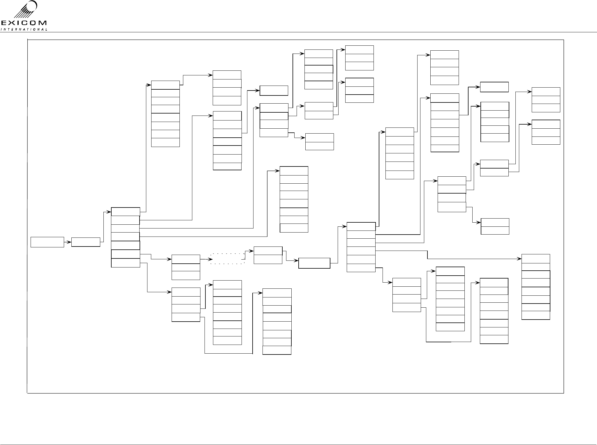
EX7100 Technical Manual - Configuring the Terminal
©1999 Exicom Technologies (1996) Ltd 3-21 Issue 1 - May 2001
EX7100 System User Menu Flow diagram (Page 1 of 2)
Exicom EX7100
Time Date Enter Password
Remote Tests
Controller
Alarms
Set Time / Date
Passwords
Oper ating Mode
Change Link ID
S/W Version
ESN
Terminal Desc
End Remote Tests
Start Tests
Alarm Log
Current Al ar ms
Link Up Time
Refer 4.3.1 Setting up a
Test Link
RF Parameters
Framer
Controller
PSU Moni toring
Set Time/Date
Change Link ID
Terminal Desc
S/W Version
ESN
Current Alarms
Alarm Log
Alarm Priorities
Link Up Time
Starting remote menu
session
List of ESNs
Antenna Align
Tx Power
Chan Increment
Tx Fr equency
Loop Volts
Tx Temperature
Rx Fr equency
5kHz 6.25kHz
G703 Contra
Sync Data
G703 Codir
Subscriber
Exchange
Sync Data
G703
Loopback
Remote
Local
+15 VDC Rail
-15 VDC Rail
Char ge Current
-5 VDC Rail
+5 VDC Raill
Input Current
Ter minal 100%
Term On Demand
Repeater 100%
Rptr On Demand
Tx Power
Chan Increment
Tx Frequency
Loop Volts
Tx Temperatur e
Rx Frequency
+24 VDC Rai ll
+15 VDC Rail
Input Voltage
-15 VDC Rail
Char ge Current
-5 VDC Rail
+5 VDC Raill
Input Cur rent
5kHz 6.25kHz
Terminal 100%
Term On Demand
Repeater 100%
Rptr On Demand
G703 Contra
Sync Data
G703 Codir
Subscriber
Exchange
Sync Data
G703
Remote
Local
1 Hr
3 Hrs
Off
6 Hrs
18 Hrs
12 Hrs
9 Hrs
24 Hrs
Alarm Priorities
Change Freqs
RSSI Tx Data Clock
BER
Interface
3 Hrs
6 Hrs
18 Hr s
12 Hr s
9 Hrs
24 Hrs
1 Hr
Off
Alarms
+24 VDC Rai l
Input Voltage
Interface
Tx Data Clock
BER
RSSI
Tx Power Drop
Low RSSI
VSWR Alarm
Synth Loss
I/P Volts Faul t
Modem Lock
BER
Int. Rail Fault
Tx Power Drop
Low RSSI
VSWR Alarm
Synth Loss
I/P Volts Fault
Modem Lock
BER
Int. Rail Fault
Sync to Rx
Ext Sync Clk
Internal Ref
Rx Polarity
Tx Polarity
Clock Source
Sync to Rx
Ext Sync Cl k
Internal Ref
Rx Polarity
Tx Polarity
Clock Source
Framer
PSU Moni toring
RF Parameters
Mux Card
(X)
Mux Card
(X)
(X)
See Page 2 if Internal Mux card is fitted.
Loopback
Align Mode
Oper ating Mode
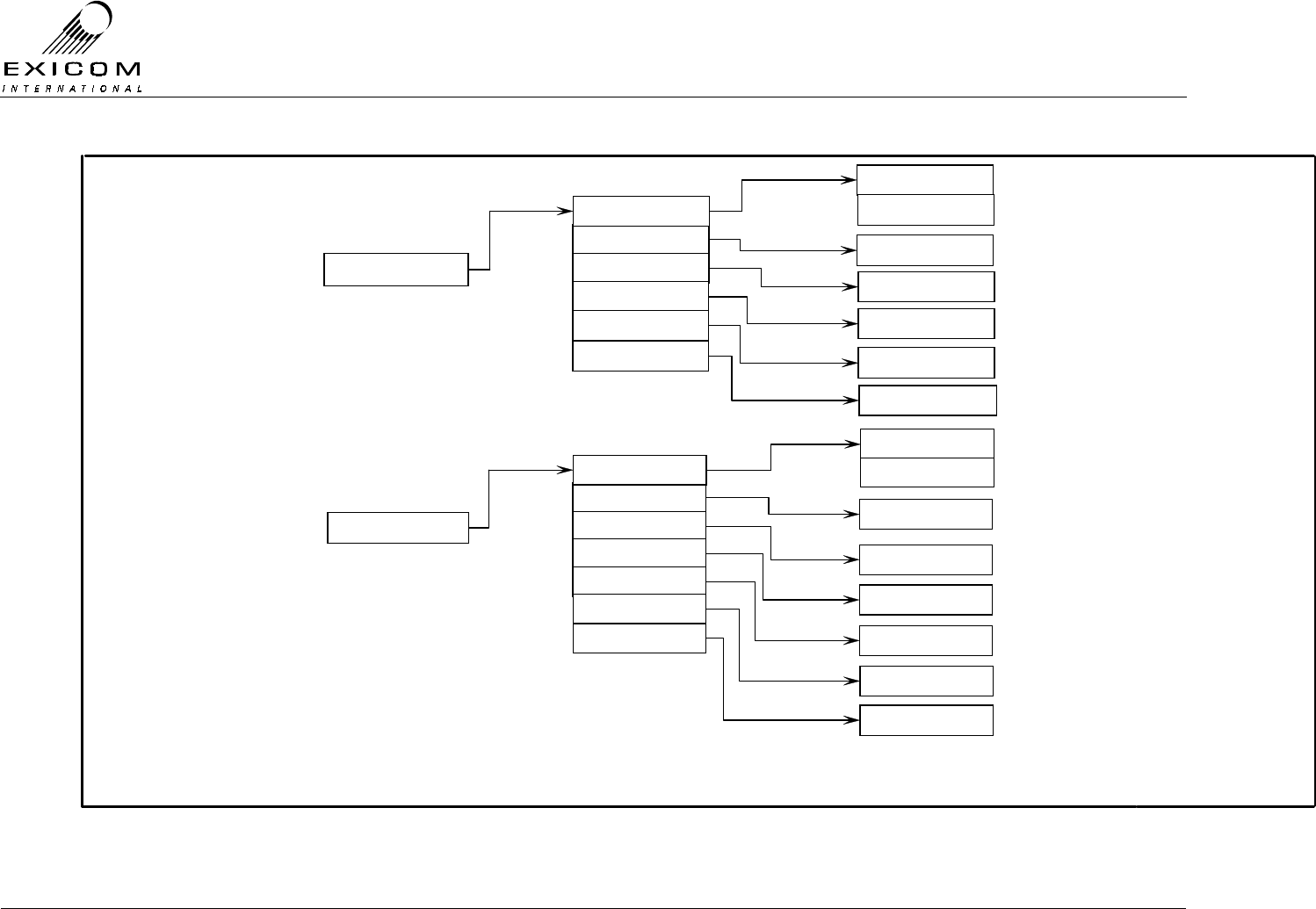
EX7100 Technical Manual - Configuring the Terminal
©1999 Exicom Technologies (1996) Ltd 3-22 Issue 1 - May 2001
EX7100 System User Menu Flow diagram (Page 2 of 2)
(X)
Subscr iber
18 Hz
25 Hz
Ch: 1 Term: 600
Ω
Ch: 1 Lvl: 0 dB
Ch: 1 Lvl: 0 dB
Ch: 1&2 Off
(X)
See Page 1 for main menu location.
Channel Setup
Metering
Tx Level
Rx Level
Operating Mode
(X)
Exchange
Ch: 1 2W 600
Ω
Ch: 1 Lvl: 0 dB
Ch 1 Lvl: 0 dB
Ch: 1&2 Off
Point to Point
Loopback
Ch: 1 Off
Termination
Metering
Tx Level
Rx Level
Ring
Loop Cur rent
Loopback
Ch: 1 25 mA
Ch: 1 Off
Ex to Sub

EX7100 Technical Manual – Monitoring and Diagnostics
©1999 Exicom Technologies (1996) Ltd 4-1 Issue 1 - February 2001
4
Monitoring and diagnostics
4.1 General
The EX7100 is equipped with a powerful monitoring and diagnostic system that may be
accessed using the six button keypad and LCD on the front panel. (Refer to Section 3.2
for information on how to use the Front Panel User Interface).
The front panel also has four LED's that indicate the operating status of the terminal, as
well as any alarms being generated by the terminal.
It is possible, via the front panel, to view how the terminal is configured (refer to Section
3), monitor various operating parameters (Refer to Section 4.2), and set up the terminal to
generate and log alarms for those parameters that may potentially cause link failure.
This facility also allows the user to access any remote terminals within the local terminal’s
RF path. (Refer to Section 4.3 Monitoring a Remote Terminal). With the addition of the
optional ELMS (Exicom Link Management System) software, monitoring of multiple
terminals is possible (Refer to Appendix B.1).
4.2 Monitoring the EX7100’s Operation
The EX7100 User Interface allows the user to monitor the operation of the various
modules that make up the radio terminal.
This Section details the monitoring method for various parameters as follows:
Note: Many of the instructions listed are similar to the configuration instructions
previously given in Section 3. It is possible to view a changeable parameter without
having to actually change it.
4.2.1 RF Parameters
> Channel Increment
> Tx Frequency
> Rx Frequency
> Tx Power
> Tx Temperature (Displays the temperature of the Power Amplifier heatsink)
> RSSI
> Synthesiser Loop Volts (Displays the loop voltage of the Rx and Tx frequency
synthesisers – Refer RF alignment within Section 7 as required.

EX7100 Technical Manual – Monitoring and Diagnostics
©1999 Exicom Technologies (1996) Ltd 4-2 Issue 1 - February 2001
1) From idle, press ‘Enter’.
Use the arrow keys to enter the First Level
password ‘1111’ and then press ‘Enter’.
2) Use the up and down arrows until the →
→→
→ is
next to RF Parameters and then press
‘Enter’.
3) Use the up and down arrows to position
the →
→→
→ next to the required parameter and
then press ‘Enter’ to view.
4) Press the ‘Escape’ key to back out of the
menu system. Pressing ‘Escape’ three
times will return the display to idle.
4.2.2 Power Supply Parameters
The power supply provides the monitoring system with the status of all voltage rails, as
well as DC input voltage and Input current drawn.
> +5 VDC Rail
> -5 VDC Rail
> +15 VDC Rail
> -15 VDC Rail
> +24 VDC Rail
> DC Input Voltage
> Input Current
> Charge Current.1
1) From idle, press ‘Enter’.
Use the arrow keys to enter the First Level
password ‘1111’ and then press ‘Enter’.
2) Use the up and down arrows until the →
→→
→ is
next to PSU Monitoring and then press
‘Enter’.
3) Use the up and down arrows to position
the →
→→
→ next to the required parameter and
then press ‘Enter’ to view.
4) Press the ‘Escape’ key to back out of the
menu system.
1 Requires an external shunt to operate. The shunt is not supplied as standard, it will need to be purchased separately.
→rf parameters
framer
RSSI
→tx power
framer
→psu monitoring
+5 VDC rail
→-5 VDC Rail
Password ∗ ∗ 1 ∗
↑
Password ∗ ∗ 1 ∗
↑
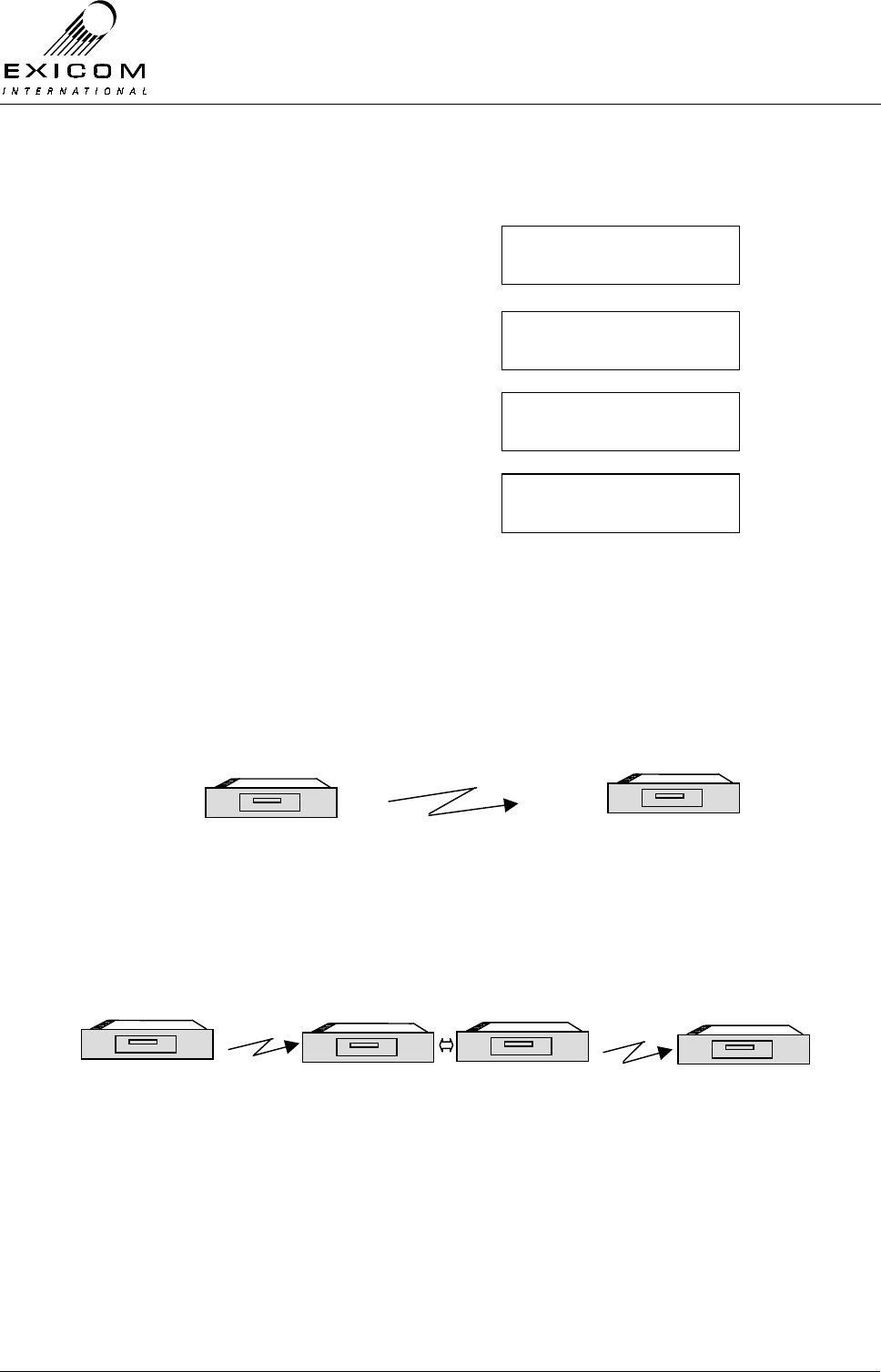
EX7100 Technical Manual – Monitoring and Diagnostics
©1999 Exicom Technologies (1996) Ltd 4-3 Issue 1 - February 2001
4.2.3 Framer Parameters
> Bit Error Rate (BER)
1) From idle, press ‘Enter’.
Use the arrow keys to enter the First Level
password ‘1111’ and then press ‘Enter’.
2) Use the up and down arrow keys to make
sure the →
→→
→ is next to Framer and then
press ‘Enter.’
3) Use the up and down arrows until the →
→→
→ is
next to BER and then press ‘Enter’.
4) The value of BER is displayed. Press
‘Enter’ to change the BER Alarm trigger
point.
5) Press the ‘Escape’ key to back out of the
menu system.
4.3 Monitoring a Remote Terminal
From any terminal, it is possible to access the configuration, monitoring and diagnostics
system of any other terminal in the RF path.
Example (1) A two terminal link.
Figure 4.1: Two Terminal Link
Example (2) A link with a repeater.
Data or Six Channel Two Data Terminals strapped as Repeaters Data or Six Channel
Figure 4.2: Two Terminal link with Repeater Terminal
EX7100
Local Terminal
EX7100
Local Terminal
EX7100
Remote Terminal
EX7100
Data
Terminal
EX7100
Data
Terminal
EX7100
Remote Terminal
Password ∗ ∗ 1 ∗
↑
RF parameters
→framer
Tx Data Clock
→ber
Ber: <1 x10E-6
→set alarm point
EX7100
EXICOM
o o
o o
o o
o
o EX7100
EX7100
EXICOM
o o
o o
o o
o
o EX7100
EX7100
EXICOM
o o
o o
o o
o
o EX7100
EX7100
EXICOM
o o
o o
o o
o
o EX7100 EX7100
EXICOM
o o
o o
o o
o
o EX7100 EX7100
EXICOM
o o
o o
o o
o
o EX7100
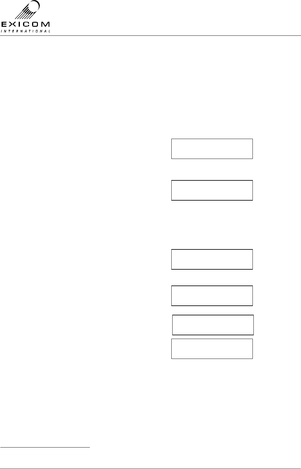
EX7100 Technical Manual – Monitoring and Diagnostics
©1999 Exicom Technologies (1996) Ltd 4-4 Issue 1 - February 2001
4.3.1 Setting Up a Test Link
To perform remote monitoring it is necessary to set up a Test Link with the terminal to be
interrogated, even if a link is already established due to normal traffic. A test link ensures
that the radio link remains in place irrespective of whether there is traffic or not.
Refer to the menu tree diagram at the end of Section 3. Following the path:
Enter Password→Remote Tests→Start Tests→
• If a link is already established due to user traffic:
There will be a short delay while the
system checks for other terminals in the
RF path
1) A list of terminal ESNs1 or terminal
descriptors (if set) found will be displayed
with the closest terminal at the top of the
list. Choose the required terminal and then
press ‘Enter’
• If a link is not already established:
1a) If any Link IDs in the path are unknown,
a Test Link can be established by
selecting Ignore Link ID: and then
pressing ‘Enter’.
1b) If all Link IDs in the path are known, a
Test Link can be established by selecting
Use Link ID: and then pressing ‘Enter’.
2) The link will take a few seconds to
establish a link.
3) A list of terminal ESNs1 or terminal
descriptors (if set) found will be displayed
with the closest terminal at the top of the
list. Choose the required terminal and then
press ‘Enter’
The menu now displays the main menu of the remote terminal. All monitoring, diagnostic,
and configuration parameters are now available for that terminal. The menu layout looks
identical to that of a local terminal menu.
1 If a terminals Terminal Descriptor has been changed from default (Refer to Section 3.4.1) it will be displayed instead of
the terminal’s ESN.
→ 12345678
23456789
→ ignore link id
use link id:xx
→ 12345678
23456789
Ignore link id
→ use link id: xx
Please wait
Setting up link
→ please wait
getting chain

EX7100 Technical Manual – Monitoring and Diagnostics
©1999 Exicom Technologies (1996) Ltd 4-5 Issue 1 - February 2001
Note 1: If the remote terminal is unable to be contacted, due to a faulty link or if another
user is accessing the terminal, a message will be displayed:
Note 2: When accessing a remote menu there will be a short delay between pressing a
key and the menu changing, due to the limited data speed of the engineering
channel.
4.3.2 Closing the Test Link
When you have finished the remote interrogation, you should close down the test link,
even if the link was already established (with data or telephone traffic). If a test link is not
closed down manually it will be shut down automatically after 10 minutes.
1) Press the ‘Escape’ key until the menu
display is as shown. Use the up and down
arrow keys to make sure the →
→→
→ is next to
End Remote Tests and then press ‘Enter’.
2) If there is no telephone or data traffic using the system, the EX7100 will close down the link
(both the Tx and Rx LED’s will go out).
If there is telephone or data traffic using the system, the EX7100 will close down the test
link, but the link will continue to operate (both the Tx and Rx LED’s will remain on).
3) Press ‘Escape’ until the display returns to idle.
Important Note:
While a terminal is being remotely accessed, it will not be able to be accessed locally. The
remote terminal display will read:
4.3.3 Changing Operating Frequencies Remotely
As previously discussed in Section 3.4.1, it is possible to configure an EX7100 terminal
remotely, with the process being identical to configuring a local terminal.
There is however, a slight change in process when changing the Operating Frequencies
or Channel Increment remotely, or locally with a link established.
Consider a link operating on Tx 450.000 MHz and Rx 455.000 MHz, with a requirement to
change this to Tx 450.050 MHz and Rx 455.050 MHz.
If we followed the procedure outlined in Section 3.4.1 for an idle terminal, the local
terminal’s frequencies would change but there would be no means of setting up a link with
the remote terminal, as the new local frequencies would no longer match the remote
terminal’s frequencies.
Remote access
Keyboard locked
Couldn’t contact
Remote terminal
Start tests
→end remote tests

EX7100 Technical Manual – Monitoring and Diagnostics
©1999 Exicom Technologies (1996) Ltd 4-6 Issue 1 - February 2001
Therefore, we would be unable to change the remote terminal’s frequencies unless we
visited the remote site. Similarly, if it were possible to change the remote terminals
frequencies, and an error was made in doing so, it would not be possible to remotely
access the terminal to amend the error.
For this reason, the EX7100 has a ‘smart’ Change Frequency command. If it is necessary
to change the frequencies of a working link, this procedure must be used.
This command allows the user to enter the new frequencies of all the terminals in the RF
path, and then issue the command to change them all simultaneously. If the link is unable
to be established on the new frequencies, the system automatically returns the link to the
original frequencies.
Important Note:
The EX7100’s front panel tuning range is limited. If a frequency change of more
than 100kHz is required, it will be necessary to manually retune some parts of the
RF Section of the radio.
Transmitter module re-tuning instructions are detailed in Sections 7.3.3 (VHF) and
7.4.3 (UHF). Receiver module re-tuning instructions are detailed in Sections 7.7.3
(VHF) and 7.8.3 (UHF). Duplexer module re-tuning instructions are given in Sections
7.9.3 (VHF) and 7.10.3 (UHF).
In addition, it may be necessary to replace the Duplexer module if a large change in
frequency is required. Refer Sections 7.9.4 (VHF) and 7.10.5 (UHF).
Procedure:
A) Use the procedure detailed in Section 4.3.1 ‘Setting Up a Test Link’, to gain access to
the remote terminal’s menu system.
B) Use the procedure detailed in Section 3.4.1 ‘Changing the Local Transmitter
Frequency’ (steps 2-9), to change the remote terminal’s Tx frequency.
Note: Although the new frequency will be displayed, it will not actually change until the
Change Frequency command is given.
C) Use the procedure detailed in Section 3.4.1 ‘Changing the Receiver Frequency’, to
change the remote terminal’s Rx frequency.
Note: Although the new frequency will be displayed, it will not actually change until the
Change frequency command is given.
D) If the link contains a repeater, press the ‘Escape’ key until the list of terminal ESNs is
displayed. Select the most remote repeater terminal and repeat steps B and C. Press
the ‘Escape’ key until the list of terminal ESNs is displayed. Select the other repeater
terminal and repeat steps B and C.
If the link does not contain a repeater, ignore this step.
E) Press the Escape key to back through the menu.
F) Use the up arrow key to make sure the →
→→
→ is next to RF Parameters, and press
‘Enter’.

EX7100 Technical Manual – Monitoring and Diagnostics
©1999 Exicom Technologies (1996) Ltd 4-7 Issue 1 - February 2001
G) Repeat steps B and C. This will enter the Local Terminal’s new frequencies.
H) Repeat step E.
I) Use the down arrow key to make sure the →
→→
→ is next to Remote Tests. Press ‘Enter’.
J) Use the down arrow key to make sure the →
→→
→ is next to Change Freqs. Press ‘Enter’.
K) Enter the Second Level Password and press ‘Enter’.
The link will shut down briefly, and then attempt to set-up a link using the new frequencies.
If it is successful, the link will continue to operate using the new frequencies. If it is unable
to set-up a link (i.e. one or more frequencies is incompatible) the link will again shut down
briefly, then set-up the link using the old frequencies.
Note: If the frequency change is successful, the following message is displayed:
This message refers only to the local RF hop. If a multi-hop frequency change has
been attempted it is recommended that the user access the terminals again, to
check that the new frequencies are correct.
If the frequency change is unsuccessful, the following message is displayed:
The procedure will need to be repeated.
Note: Any traffic using the link during a Change Frequency command will be lost.
L) Use the Close Link procedure detailed in Section 4.3.2 to close down the Test Link.
4.4 EX7100 Internal Alarms
The EX7100 terminal generates the following internal alarms:
> Input Voltage (DC input voltage out of range: approx. 5% from shutdown voltages)
> Low RSSI (Adjustable alarm set point, refer to Section 4.4.4)
> Tx Power Drop (3dB drop below current menu setting)
> High VSWR
> High BER (Adjustable alarm set point, refer to Section 4.2.3)
> Modem Lock (Modems not synchronised)
> Synth Loss (Rx or Tx frequency not locked)
> Link Up Too Long
> Link Failed (Locally generated link failure)
Change freqs ok.
Using new freqs
Change freqs fail.
Using old freqs

EX7100 Technical Manual – Monitoring and Diagnostics
©1999 Exicom Technologies (1996) Ltd 4-8 Issue 1 - February 2001
> Internal Voltage Rails (Internal voltage rails out of range: approx. ± 10%)
> Over Temperature Alarm (UHF 10 Watt system only, activates if Heatsink
temperature exceeds 60°C)
The user is able to assign either a high or a low priority to each of these alarms. When a
high priority alarm occurs, an opto-isolated output closes. When a low priority alarm
occurs, a second opto-isolated output closes. In either case, an alarm message is sent out
of the LMS port.
If a high priority alarm is triggered, a link set-up is attempted (if a link is not already in
place) and the alarm transported to the remote end. At the remote end, and any
intermediate repeater sites, the high priority output is activated and an alarm message is
sent out to the LMS port. At any site, the user is able to scroll through active local and
remote alarms via the front panel LCD.
When any alarm event occurs, local or remote, the alarm LED on the front panel flashes
red. When the user acknowledges the alarm using the front panel, the LED stops flashing
but continues to glow red.1
4.4.1 Acknowledging an Alarm
To acknowledge an alarm, follow the menu path:
Enter Password→Alarms→Current Alarms
Use the up and down arrow keys to
scroll through the current alarms until the
new alarm is displayed. This is
recognisable by the flashing * in the
bottom left corner.
Press ‘Enter’ to acknowledge the alarm.
Note: To view the time and date stamp of the
alarm toggle the left or right arrow key.
When the alarm clears, the front panel LED extinguishes. If more than one alarm is
present at one time, the above conditions apply until all alarms are acknowledged, and
then cleared.
Alarm events (either activating or clearing of any local or remote alarm) are stored in a log.
Each entry includes a time and date stamp. The user is able to scroll through the alarm
log.
Note: The alarm log can hold 32 events. When the alarm log is full, the oldest alarm is
overwritten. In the event of a power failure, the alarm log will be lost.
4.4.2 Setting Alarm Priorities
To set Alarm Priorities (high or Low), follow the menu path:
Enter Password→Alarms→Priorities
1 Any remote alarm(s) will be cleared whenever the link closes down, either by a user-action or a link failure.
Local alarm
‘*’ Low RSSI
EX7100 Technical Manual – Monitoring and Diagnostics
©1999 Exicom Technologies (1996) Ltd 4-9 Issue 1 - February 2001
1) Press ‘Enter’. You will be given a list of all
alarms available within the terminal
2) Use the up and down arrow keys to select
the alarm you wish to set and then press
‘Enter’ to select.
3) The asterisk (*) indicates which priority is
set for that alarm. Use the left and right
arrow keys to change the priority and then
press ‘Enter’ to accept the change.
4) Continue to check/set the priorities for
each alarm and then press ‘Escape’ until
the display returns to idle.
4.4.3 Link Up Time Alarm
The EX7100 provides an alarm to indicate when the link has been up longer than the set
time limit. This may be useful in the case where a site is battery/solar powered and it is
necessary to know if the link is being held up for any reason.
The Link Up Time Alarm may be set for the following times:
Off, 1 Hour, 3 Hours, 6 Hours, 9 Hours, 12 Hours, 18 Hours, 24 Hours.
To set the Link Up Time Alarm:
1) From idle, press ‘Enter’
Use the arrow keys to enter the First Level
password ‘1111’ and then press ‘Enter’.
2) Use the up and down arrow keys to make
sure the →
→→
→ is next to Alarms and then
press ‘Enter’
3) Use the up and down arrow keys to make
sure the →
→→
→ is next to Link Up Time and
then press ‘Enter’.
4) Use the up and down arrow keys to
choose the required alarm time and then
press ‘Enter’ to accept.
Note that the currently selected option is
indicated by an asterisk.
5) Press ‘Escape’ until the display returns to
idle
Alarm Log
→ Priorities
Low RSSI
→Tx Power drop
Tx power drop
* low High
Remote tests
→Alarms
Priorities
→Link up time
Off
→1 hour
Password ∗ ∗ 1 ∗
↑
EX7100 Technical Manual – Monitoring and Diagnostics
©1999 Exicom Technologies (1996) Ltd 4-10 Issue 1 - February 2001
4.4.4 Low RSSI Alarm
The user may set an RF level (-40 dBm to -106 dBm) at which the Low RSSI Alarm will
trigger. To set this trigger point:
1) From idle, press ‘Enter’
Use the arrow keys to enter the First Level
password ‘1111’ and then press ‘Enter’.
2) Use the up and down arrow keys until the
→
→→
→ is next to RF Parameters and then
press ‘Enter’
3) Use the up and down arrow keys to
position the →
→→
→ next to RSSI and then
press ‘Enter’.
4) Press the down arrow key then press
‘Enter’.
5) Use the up and down arrow keys to
select the required alarm trigger point,
then press ‘Enter’.
The currently selected setting is indicated
by an asterisk.
6) Press ‘Escape’ until the display returns to
idle
4.4.5 Over Temperature alarm
The UHF 10 Watt system requires fan assisted cooling, due to the extra heat generated
by the power amplifier. Two fans are controlled by the transmitter CPU. If the heatsink
temperature exceeds 45°C one fan will be turned on.
Every 40 hours (approx) the CPU will switch between the two fans to ensure an even
lifecycle. If the heatsink temperature continues to rise above 55°C, both fans will be turned
on simultaneously. If the heatsink temperature exceeds a maximum permitted level of
60°C, normally due to a total fan failure, an alarm will be generated.
4.5 Diagnostic Tools
4.5.1 System Align Mode
To enable the user to retune the EX7100’s RF section with the minimum of external test
equipment, the terminal may be put into an Align Mode.
In this mode, the internal modem is set to output fixed data patterns, with a constant AGC
level, and the transmitter is keyed on. The user is then able to retune the Transmitter
module as per the instructions in Section 7.
Note: Two modes can be used to retune the RF Modules.
→RSSI
Tx power
Rssi : -75dbm
→set alarm point
Password ∗ ∗ 1 ∗
↑
→rf parameters
framer
* -100 dbm
→-98 dbm
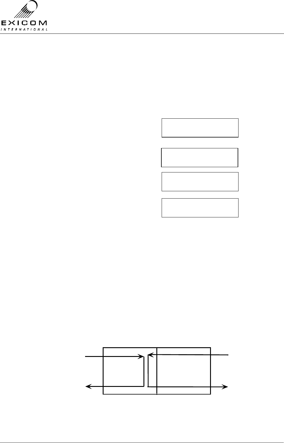
EX7100 Technical Manual – Monitoring and Diagnostics
©1999 Exicom Technologies (1996) Ltd 4-11 Issue 1 - February 2001
The ‘CW’ mode provides a carrier output only. This enables the user to verify the
transmitter operating frequency using a standard frequency counter.
The ‘DSBSC’ mode provides a double side band, suppressed carrier output, to enable the
user to adjust the transmitter carrier null, and also to measure Transmitter RF Power
(PEP).
1) Align Mode cannot be accessed if the link is established or the Transmitter is on.
Ensure this is not the case by setting the Terminal’s Operating Mode to “On-
demand”.
2) From idle, press ‘Enter’
Use the arrow keys to enter the First Level
password ‘1111’ and then press ‘Enter’.
3) Use the up and down arrow keys to make
sure the →
→→
→ is next to Controller and then
press ‘Enter’
4) Use the up and down arrow keys to make
sure the →
→→
→ is next to Align Mode and then
press ‘Enter’.
5) Use the keypad to select the required
modulation and Tx power level, then press
‘Enter’.
6) Press ‘Escape’ to disable and exit out of
Align Mode.
Key: MOD = Modulation.
CW = Carrier only.
DSBSC = Double side band at +/- 8kHz from carrier.
Tx = Transmit power level.
Low = Set to lowest menu setting.
Normal = Set to current user setting.
4.5.2 Digital Loopbacks
The EX7100 is able to loopback the 64kbps digital data in the following configurations:
Figure 4.3: Digital Loopback Configurations
→Controller
Rf Parameters
S/w version
→Align Mode
→mod: ∗ cw dsbsc
tx: ∗ low norm
Password ∗ ∗ 1 ∗
↑
Framer
Transmit RF
Received RF
Received Data
Transmit Data
EX7100
Local Loopback Remote Loopback
RF Section
EX7100 Technical Manual – Monitoring and Diagnostics
©1999 Exicom Technologies (1996) Ltd 4-12 Issue 1 - February 2001
Local Loopback
In Local loopback mode, the transmit 64kbps digital data stream, from the user interface,
is looped within the framer to the receive 64kbps digital data stream, back to the user
equipment. This enables the user to check the interface between the EX7100 and the user
equipment.
Notes: Local loopback operates for both G.703 and Synchronous Data inputs.
Remote Loopback
In Remote Loopback mode, the received RF into the EX7100 terminal is looped to the
transmit RF line. This enables the user to check the radio path of the system.
Both loopbacks can be enabled for the local terminal as well as the remote terminal.
Enabling Digital Loopbacks
1) From idle, press ‘Enter’.
Use the arrow keys to enter the First Level
password ‘1111’ and then press ‘Enter’.
2) Use the up and down arrow keys to make
sure the →
→→
→ is next to Framer and then
press ‘Enter’.
3) Use the up and down arrow keys to make
sure the →
→→
→ is next to Loopback and then
press ‘Enter’.
4) Use the up and down arrow keys to
choose the required loopback and then
press ‘Enter’.
5) Use the keypad to enable the loopback
function.
Note: Ensure that the loopback mode is disabled when testing is completed.
Warning: Digital loopbacks should only be used with the system set for G.703 or V.35
(sync data) input. Do not attempt to use the digital loopbacks when the
EX7100 interface is set to Exchange or Subscriber. Doing this may cause the
subscriber telephones to ring continuously.
Password ∗ ∗ 1 ∗
↑
RF parameters
→framer
ber
→loopback
local
→remote
off
→on
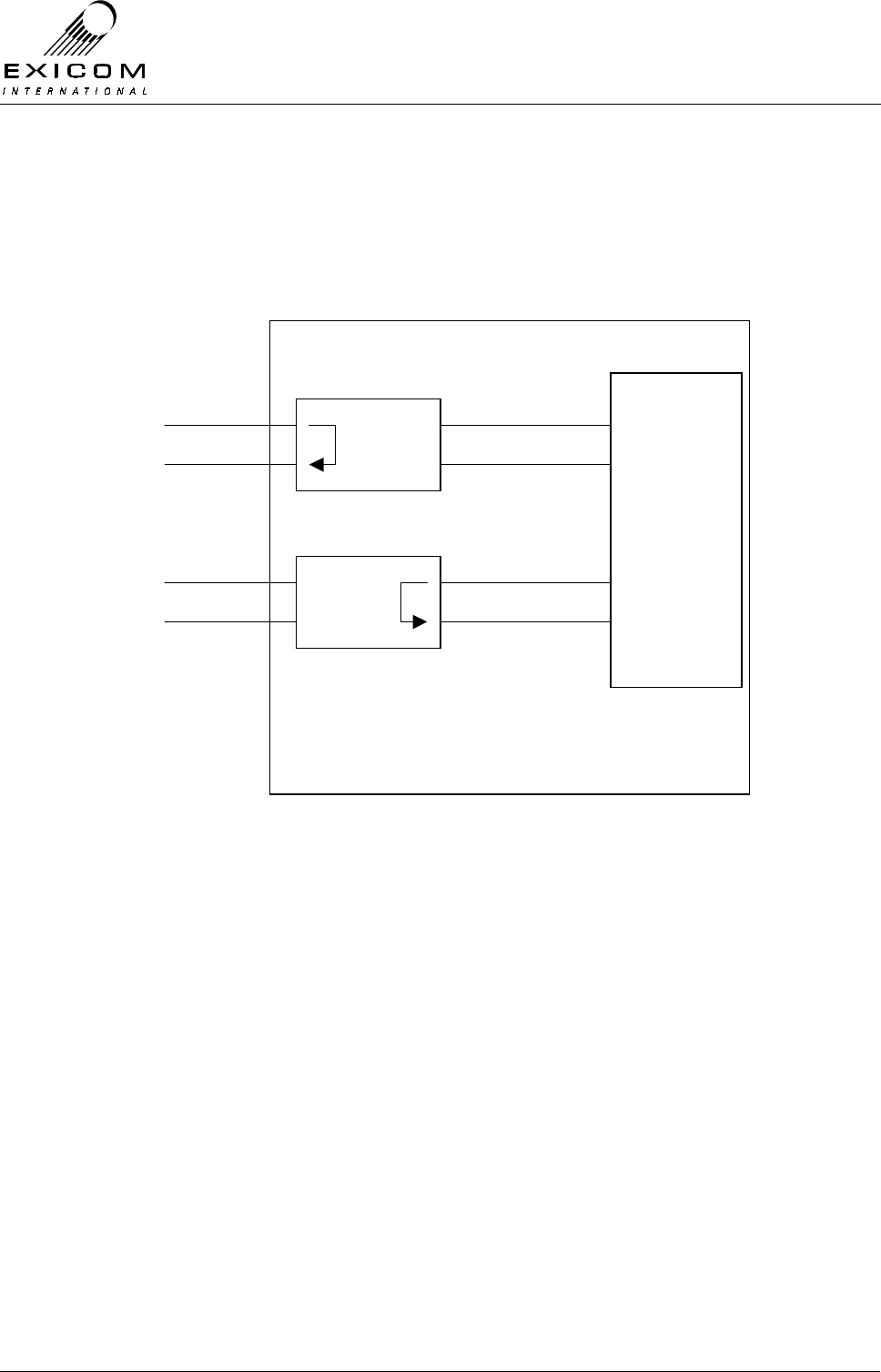
EX7100 Technical Manual – Monitoring and Diagnostics
©1999 Exicom Technologies (1996) Ltd 4-13 Issue 1 - February 2001
4.5.3 Analogue Loopbacks
The six channel telephone version of the EX7100 is equipped with the ability to loop back
the audio on each of the six analogue lines. This function is done within the digital audio
processing section of the line interface card and therefore is transparent to the interface
configuration (2-wire or 4-wire+E&M).
Figure 4.4: Analogue Loopback Configurations
Local Loopback
Each channel may be put into local loopback mode from the front panel of the EX7100
terminal. In this mode, the transmit audio (into the EX7100 terminal) is looped back to the
received audio (out of the terminal), within the DSLAC (Dual Subscriber Line Audio
Circuit) device.
The user is now able to send an analogue signal into the radio and monitor it across the
same line (using a suitable test instrument with built in hybrid network). It is possible to
perform a similar test using a standard telephone connected to the line, but due to echo
cancellation effects, the received audio will sound distorted.
This feature enables a technician to confirm that the EX7100 line interface circuitry is
operating correctly.
Remote Loopback
Each analogue channel may be put into remote loopback mode from the front panel of the
EX7100. In this mode, the received audio from the remote terminal is looped back to the
transmit audio path.
From the remote terminal, a technician is able to send a signal down the line and monitor
it from the same location (using suitable test equipment with built in hybrid network).
DSLAC
LOCAL
LOOPBACK
LINE 1…6
DSLAC
REMOTE
LOOPBACK
LINE 1…6
DSPs

EX7100 Technical Manual – Monitoring and Diagnostics
©1999 Exicom Technologies (1996) Ltd 4-14 Issue 1 - February 2001
This feature allows a technician to distinguish whether a fault is within the radio
equipment, or on the external telephone line.
Enabling Analogue Loopbacks
1) From idle, press ‘Enter’
Use the arrow keys to enter the First Level
password ‘1111’ and then press ‘Enter’.
2) Use the up and down arrow keys to make
sure the →
→→
→ is next to Exchange/Subscriber
and then press ‘Enter’
3) Use the up and down arrow keys to make
sure the →
→→
→ is next to Loopback and then
press ‘Enter’.
4) Use the keypad to set the required
channel to the required loopback mode
and then press ‘Enter’ to accept.
5) Press ‘Escape’ until the display returns to
idle
Note: During loopback testing the channel is not available to user traffic. Ensure that the
loopback mode is disabled when testing is complete.
4.6 Bit Error Rate Testing
4.6.1 General
At some time after installation of the EX7100, the user may wish to perform a bit error rate
test in order to confirm that the system is operating correctly.
A BER test may be performed on both configurations of EX7100: 64kbps data or
telephone.
Testing of a telephone system is possible by performing the test at the 64kbps digital level
using the G.703 or Synchronous data interface.
There are a number of levels of BER testing that may be performed on the EX7100 to
enable the user to pin-point the location of a potential fault.
A) End-to-End one direction test: This requires a Bit Error Rate Tester (BERT) at both
ends of the link.
B) Full round-trip test: This may be performed using a single BERT (capable of sending
and receiving simultaneously) utilising the remote digital loopback feature of the
EX7100.
C) Local Interface test: As per B) above, but utilising the local loopback feature of the
local EX7100 terminal.
It should be noted that the results obtained from a round trip test will produce a BER twice
that of a single direction test.
Password ∗ ∗ 1 ∗
↑
Psu monitoring
→Subscriber
Loop current
→loopback
Ch: 1 off
↑
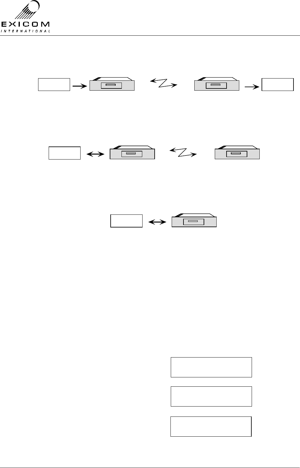
EX7100 Technical Manual – Monitoring and Diagnostics
©1999 Exicom Technologies (1996) Ltd 4-15 Issue 1 - February 2001
Important Note:
During the BER test, the radio link will not be available to normal traffic.
Figure 4.5: End-to-End Bit Error Rate Test
Figure 4.6: Round-Trip Bit Error Rate Test
Figure 4.7: Local Interface Bit Error Rate Test
4.6.2 BER Testing an EX7100: End-to-End
A) Connect the BERT equipment to the digital interface port of both EX7100 terminals
(G.703, or Sync Data) as required.
B) Set the sending BERT equipment to provide the clocking source for the test.
C) Set the interfaces of both EX7100 terminals to match the interface of the BERT
equipment - G.703 or V.35 (sync data) - as follows:
1) From idle, press ‘Enter’
Use the arrow keys to enter the First Level
password ‘1111’ and then press ‘Enter’.
2) Use the up and down arrows until the →
→→
→ is
next to Framer and then press ‘Enter’
3) Use the up and down arrow keys to make
sure the → is next to Interface and press
‘Enter.’
EX7100
EXICOM
o o
o o
o o
o
oEX7100 EX7100
EXICOM
o o
o o
o o
o
oEX7100
BERT BERT
Bit error rate
tester set to
transmit.
Bit error rate
tester set to
receive.
EX7100
EXICOM
o o
o o
o o
o
oEX7100 EX7100
EXICOM
o o
o o
o o
o
oEX7100
BERT
Bit error rate
tester set to
transmit and
receive.
EX7100 set for
remote loopback
EX7100
EXICOM
o o
o o
o o
o
oEX7100
BERT
Bit error rate
tester set to
transmit and
receive.
EX7100 set for
local loopback
Password ∗ ∗ 1 ∗
↑
Rf parameters
→framer
→interface
Tx Data Clock
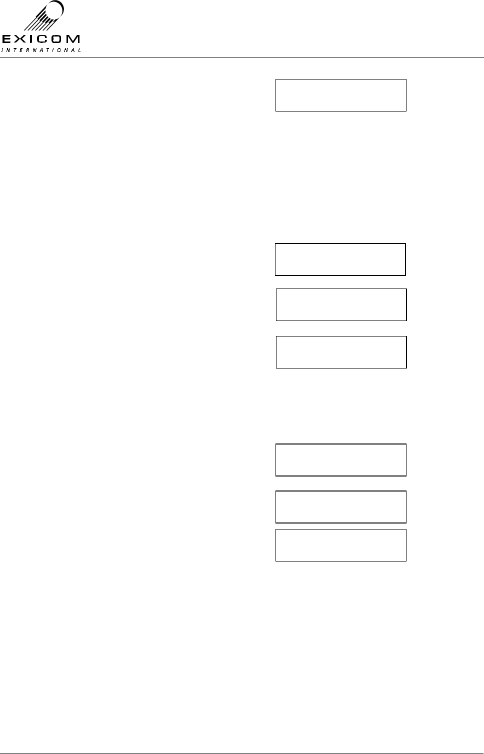
EX7100 Technical Manual – Monitoring and Diagnostics
©1999 Exicom Technologies (1996) Ltd 4-16 Issue 1 - February 2001
4) Use the up and down arrow keys to make
sure the → is next to the required
interface type. An ∗ indicates the current
interface.
Press ‘Enter’ to accept.
5) Press ‘Escape’ once to return to the
previous menu.
D) Set the EX7100 terminals so that the Transmitted data is clocked from the received
data stream, as follows:
1) Use the up and down arrow keys to make
sure the → is next to Tx Data Clock.
Press ‘Enter.’
2) Use the up and down arrows to select the
digital interface being used.
Press ‘Enter.’
3) Select the synchronisation source
required.
Press ‘Enter.’
4) Press ‘Escape’ until the main menu is
displayed.
E) Set both EX7100 terminals to 100% operation as follows:
1) Use the up and down arrow keys to make
sure the →
→→
→ is next to Controller.
Press ‘Enter.’
2) The screen will read Operating Mode.
Press ‘Enter’
3) Use the up and down arrow keys to
choose Terminal 100%, and press ‘Enter’
4) Press ‘Escape’ until the display returns to
idle.
F) The BER test may now begin. When complete, return each terminal to its original
configuration.
→G.703 codir
G.703 contra
Interface
→Tx Data Clock
→G.703
Sync data
int ref
→Sync to rx
→operating mode
set Time / date
→controller
rf parameters
→terminal 100%
term on demand
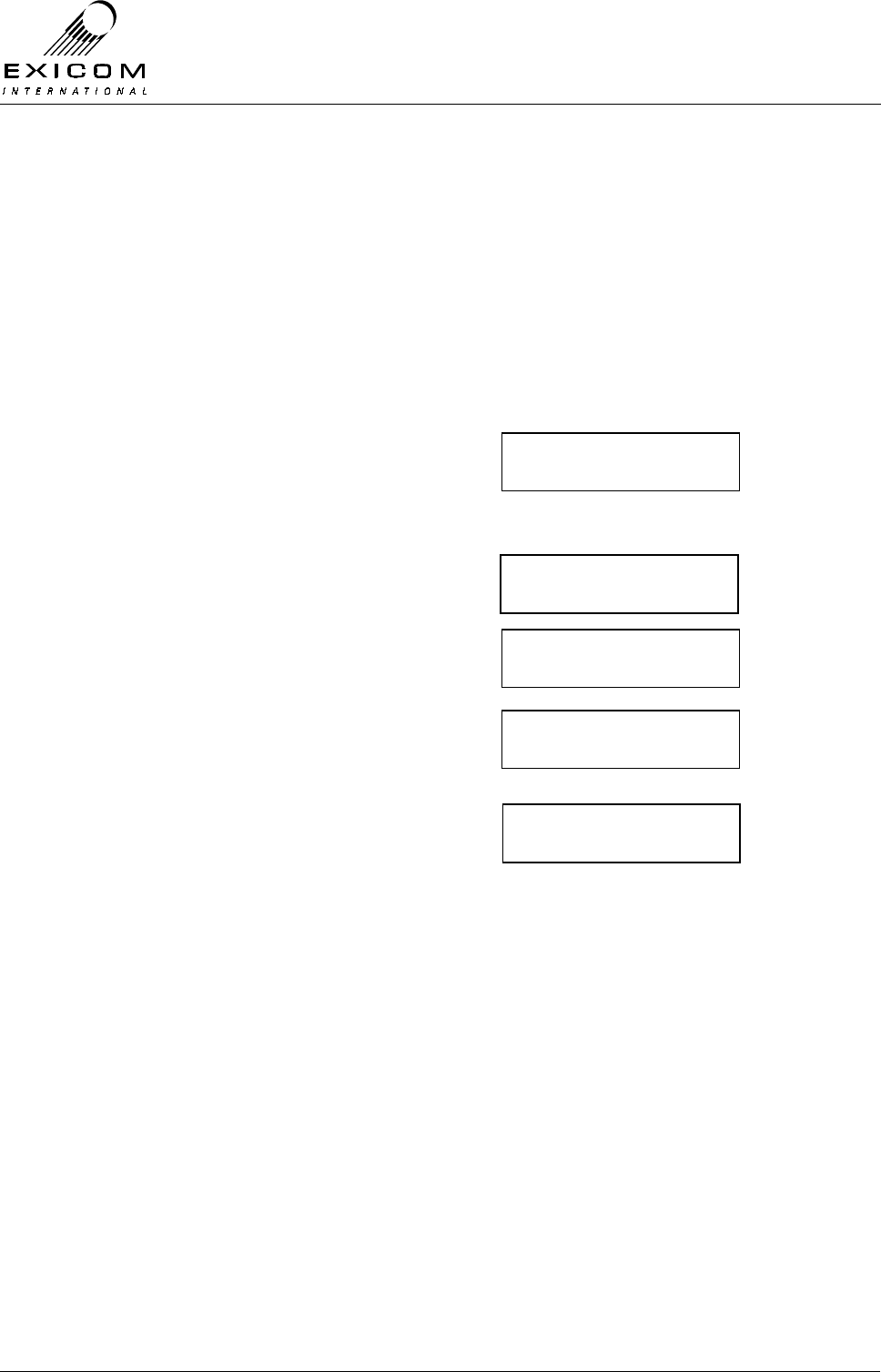
EX7100 Technical Manual – Monitoring and Diagnostics
©1999 Exicom Technologies (1996) Ltd 4-17 Issue 1 - February 2001
4.6.3 BER Testing an EX7100: Round-Trip
A) Connect a BERT, set to send and receive simultaneously, to the local EX7100
terminal.
B) Follow steps B-E above to set the EX7100 terminals for the correct interface, clock
sync, and 100% operation.
C) Set the remote EX7100 terminal to Digital Remote Loopback mode by first setting up
a remote test link and accessing the remote terminal (refer to Section 4.3.1) then
following the procedure below:
1) From idle, press ‘Enter’
Use the arrow keys to enter the First Level
password ‘1111’ and then press ‘Enter’.
2) Use the up and down arrow keys to make
sure the →
→→
→ is next to Framer and then
press ‘Enter’
3) Use the up and down arrow keys to make
sure the →
→→
→ is next to Loopback and then
press ‘Enter’.
4) Use the up and down arrow keys to
choose the required loopback and then
press ‘Enter’.
5) Use the keypad to turn the loopback
function on.
D) The BER test may now begin. Remember to disable the loopback, close the test link,
and return the EX7100 terminals to their original configurations when finished.
4.6.4 BER testing an EX7100: Local Interface.
A) Connect a BERT, set to send and receive, to the local EX7100 terminal.
B) Set the EX7100 terminal to the correct interface and clock sync using the steps in
Section 4.6.2.
C) Using the instructions given earlier as a guide, set the EX7100 terminal to Digital
Local Loopback mode.
D) The BER test may now begin. Remember to disable the loopback and return the
terminal to its original configuration when finished.
Password ∗ ∗ 1 ∗
↑
RF parameters
→framer
ber
→loopback
local
→remote
off
→on
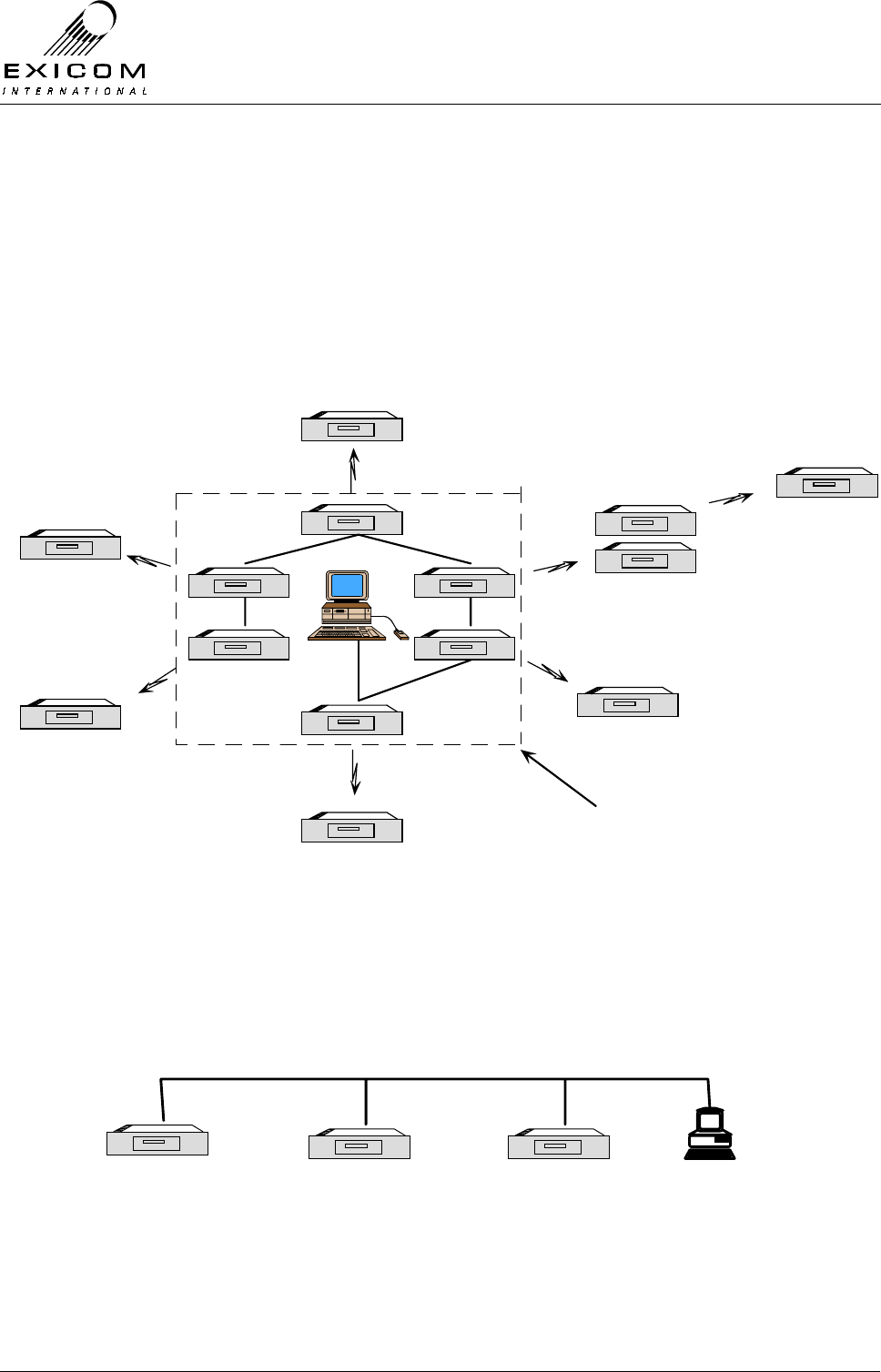
EX7100 Technical Manual – Monitoring and Diagnostics
©1999 Exicom Technologies (1996) Ltd 4-18 Issue 1 - February 2001
4.7 Networking EX7100 Terminals
4.7.1 General
It is possible to create a small network of EX7100 links by connecting the management
channel of multiple terminals together at a local site. This enables a user to monitor and
configure any other terminal in the network, from an ELMS configured PC, using the on-
board remote diagnostic feature.
When combined with ELMS (Exicom Link Management System – refer to Appendix B) an
extensive alarm logging system can be established.
Figure 4.8: Networking EX7100 terminals
4.7.2 Interconnection of Local Terminals.
Interconnection of each EX7100 terminal’s management channel is achieved by simply
daisy-chaining the RS-485 Bus which appears on the LMS port of each local terminal.
Cabling should be screened and pin-out information is detailed in Appendix A.1.
Example: Three terminal bussed site.
Figure 4.9: Three Terminal Bussed Site
EX7100
EXICOM
o o
o o
o o
o
oEX7100
EX7100
EXICOM
o o
o o
o o
o
oEX7100
EX7100
EXICOM
o o
o o
o o
o
oEX7100
EX7100
EXICOM
o o
o o
o o
o
oEX7100
EX7100
EXICOM
o o
o o
o o
o
oEX7100
EX7100
EXICOM
o o
o o
o o
o
oEX7100
EX7100
EXICOM
o o
o o
o o
o
oEX7100
EX7100
EXICOM
o o
o o
o o
o
oEX7100
EX7100
EXICOM
o o
o o
o o
o
oEX7100
EX7100
EXICOM
o o
o o
o o
o
oEX7100
EX7100
EXICOM
o o
o o
o o
o
oEX7100
EX7100
EXICOM
o o
o o
o o
o
oEX7100
RS-485
EX7100
EXICOM
o o
o o
o o
o
oEX7100
EX7100
EXICOM
o o
o o
o o
o
oEX7100
Repeater
Local Site
EX7100
EXICOM
o o
o o
o o
o
oEX7100 EX7100
EXICOM
o o
o o
o o
o
oEX7100 EX7100
EXICOM
o o
o o
o o
o
oEX7100
Terminal 1
LMS Port
Terminal 2
LMS Port Terminal 3
LMS Port ELMS PC

EX7100 Technical Manual – Monitoring and Diagnostics
©1999 Exicom Technologies (1996) Ltd 4-19 Issue 1 - February 2001
The following table shows the pin to pin connections required for the LMS port connector
Terminal 1 – Terminal 2 Terminal 2 – Terminal 3 Terminal 3 – ELMS PC
Pin 1 - Pin 1 Pin 1 - Pin 1 Pin 3 - RS232 Tx
Pin 2 - Pin 2 Pin 2 - Pin 2 Pin 4 - RS232 Rx
Pin 5 - Pin 5 Pin 5 - Pin 5 Pin 5 – RS232 ground
Note: The ELMS PC connects to terminal three using RS-232. The terminals
communicate with each other using RS-485
4.7.3 Accessing Bussed Terminals.
Using an ELMS configured PC, the user may access any local terminal, or the remote
terminal of any link. An instruction on how to use ELMS is provided within the program.

EX7100 Technical Manual – Monitoring and Diagnostics
©1999 Exicom Technologies (1996) Ltd 4-20 Issue 1 - February 2001
This page intentionally left blank

EX7100 Technical Manual - Troubleshooting
©1999 Exicom Technologies (1996) Ltd 5-1 Issue 1 - February 2001
5
Trouble Shooting the EX7100
5.1 General
This chapter describes some methods of identifying problems with the EX7100 and
suggests possible solutions.
The EX7100 has powerful fault diagnosis tools built in. Internal alarm monitoring,
metering and configuration information are available on the front panel and at remote
terminals. Refer to Section 4 for more details on the use of these diagnostic tools.
5.2 Configuration Issues
Configuration problems are not normally an issue with links that are already in operation,
but an initial mis-configuration can prevent an EX7100 link from operating.
When changing modules within the EX7100, configuration problems can arise. This is
because the modules carry the configuration information relevant to them – e.g. the Line
Module carries line level and the other configuration variables relevant to the Line
Module. An exception is that all RF configuration parameters are carried on the
Transmitter module.

EX7100 Technical Manual - Troubleshooting
©1999 Exicom Technologies (1996) Ltd 5-2 Issue 1 - February 2001
This page left intentionally blank.

EX7100 Technical Manual - Troubleshooting
©1999 Exicom Technologies (1996) Ltd 5-3 Issue 1 - February 2001
Symptoms Possible Causes How To Fix Additional Comments
Antenna or feeder fault. Replace faulty antenna and/or
feeder.
Duplexer faulty or out of
alignment.
Check, align or replace Duplex
Filter.
Low transmit power, low RSSI and
poor VSWR
Transmit and/or receive frequency
incorrect.
Set terminals to correct transmit
and receive frequencies.
Low transmit power, VSWR &
RSSI OK
Transmit power set low. Set terminal to the correct transmit
power level.
Low transmit power, high bit error
rate, VSWR & RSSI OK.
Faulty Transmitter module or
Power Amplifier module.
See Sections 7.3 to 7.6.
Higher than usual bit error rate or
poor sensitivity, transmit power,
RSSI & VSWR OK.
Transmitter or receiver may have
drifted off frequency.
Return to Exicom for alignment.
Low RSSI reading. Can be caused by low transmit
power, feeder and/or antenna
problems, antenna alignment and
receiver problems.
Refer to the appropriate sections
of this manual.
Low transmit power or poor
receiver sensitivity usually cause
problems in one direction only.
Feeder and antenna problems
effect both directions of the link.

EX7100 Technical Manual - Troubleshooting
©1999 Exicom Technologies (1996) Ltd 5-4 Issue 1 - February 2001
Symptoms Possible Causes How To Fix Additional Comments
Rx Lock frequently lost. Interference, intermittent
connector/feeder/antenna fault.
Marginal RF path.
A communications scanning
receiver can be very useful to
identify interference sources.
Measurements of transmit power
at antenna, substitution of feeders
and antennas.
A high power attenuator can be
used to confirm the available fade
margin.
Problems with repeater operation. G703 coaxes not crossed over. Crossover coaxes.
No dial tone, Rx Lock present. Line connections to EX7100. Line
Interface module fault.
Check line connections. Refer to
Section 7.13 for details.
Is the fault common to all six lines?
Loop back testing of the line
interfaces can be a useful
diagnostic tool.
Link will not set-up, Tx LED not on System configured for On-demand
Mode
Refer to Section 3.4.1 for details

EX7100 Technical Manual - Cover Removal
©1999 Exicom Technologies (1996) Ltd 6-1 Issue 1 - February 2001
6
EX7100 Top and Bottom Cover Removal
The Terminal contains semi-conductor components that are
sensitive to electrostatic damage.
Electrostatic sensitive devices should only be stored and
transported inside electrically conductive static shielding
bags. Fault finding and module replacement must be
performed at “electrostatically safe work stations” where the
work bench surface; soldering iron and the operator are all
earthed to prevent the build up of harmful electrostatic
charges.
6.1 Procedure
To gain service access to any of the modules, the top or bottom covers must be removed
as follows:
1. Isolate the EX7100 Terminal from the incoming DC supply by removing the DC input
wires from the rear panel terminal block. It may also be necessary to remove any
signalling and antenna cabling.
2. Remove either cover as required by removing the screws. Keep all screws in a safe
place for later replacement.
Warning: The VHF Duplexer module is attached to the underside of the top cover. Extra
care must be taken when removing this cover so as not to damage the RF
cabling connecting the duplexer to the modules within the terminal.
The UHF Duplexer and associated filters are attached to the outside of the
top cover. Before disconnecting the RF cables to the rear panel, care should
be taken to note the correct cable connection.

EX7100 Technical Manual - Cover Removal
©1999 Exicom Technologies (1996) Ltd 6-2 Issue 1 - February 2001
This page intentionally left blank

EX7100 Technical Manual - Module Descriptions
©1999 Exicom Technologies (1996) Ltd 7-1 Issue 3 - May 2001
7
Module Descriptions
7.1 General
The EX7100 Terminal consists of the following Modules:
General (Non-RF) Modules
> Power Supply Module Type 2964,
> Modem/Controller Module Type 2966,
> Front Panel Type 2994,
RF Modules
> VHF Transmitter Module Type 8027 or
UHF Transmitter Module Type 8053,
UHF CPU Module Type 8044 (sub-module of UHF Tx Module Type 8053),
> VHF RF Power Amplifier Module Type 8028 or
UHF RF Power Amplifier Module Type 8048 (10 Watt),
> VHF Receiver Module Type 8029 or
UHF Receiver Module Type 8054,
> VHF Front-End Module Type 8018 (sub-module of VHF Rx Module Type 8029) or
UHF Front-End Module Type 8055 (sub-module of UHF Rx Module Type 8054),
> VHF Duplexer Module Type 8013 or
UHF Duplexer (& Filters) Module Type 8045,
Line Interface Modules: (present in the six channel variant only)
> Two wire 6-Channel Exchange Line Interface Module Type 2967,
Four wire Module Type 2967 (optional sub-module of Interface Type 2967),
> Two wire 6-Channel Subscriber Line Interface Module Type 2971,
> Isolated Power Supply Type 2990 (sub-module of each Line Interface module)
Refer to Figures 7.1 to 7.3 for module locations (Front Panel Type 2994 and Duplexer
modules are not shown).
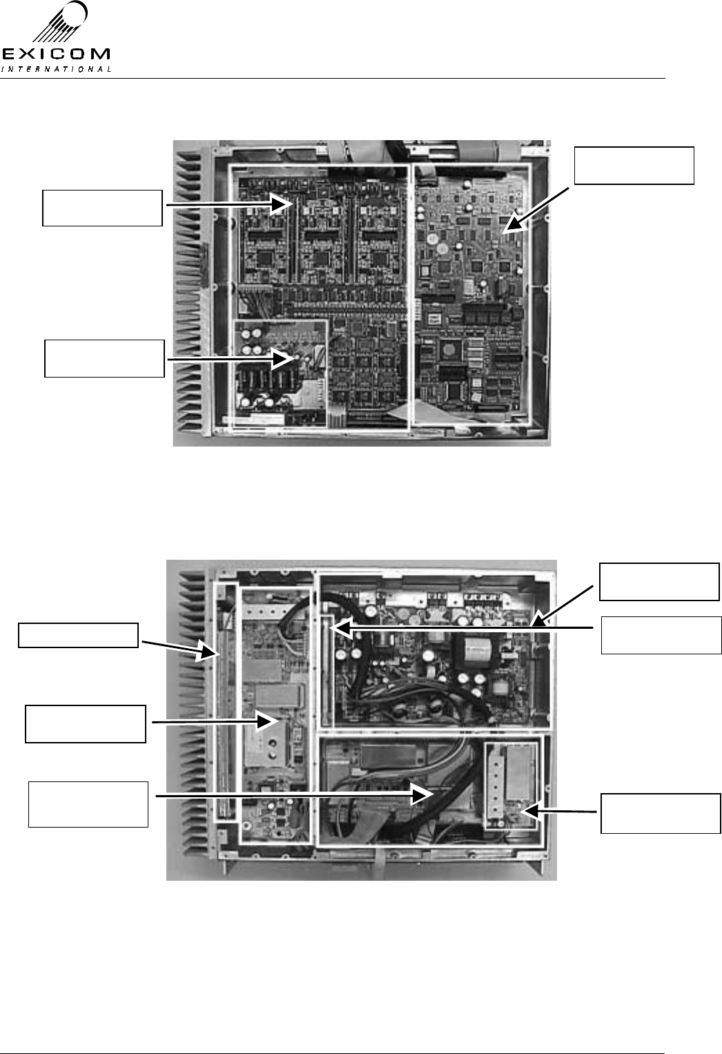
EX7100 Technical Manual - Module Descriptions
©1999 Exicom Technologies (1996) Ltd 7-2 Issue 3 - May 2001
Figure 7.1: EX7100 Terminal with Top Cover Removed
Note: VHF and UHF Terminals are identical with the Top Cover removed.
Figure 7.2: VHF EX7100 Terminal with Bottom Cover Removed
Isolated Power
Supply Type 2990
Line Interface Type
2967 or 2971
Modem/Controller
Type 2966
PA Type 8028
Transmitter Type
8027
Power Supply Type
2964
Receiver Front-End
Type 8018
Receiver Type
8029
PSU Measurement
Board Type 2998
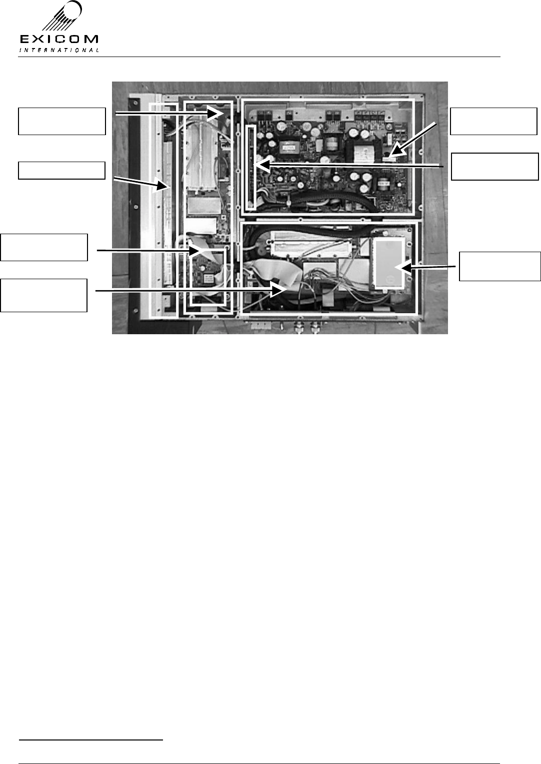
EX7100 Technical Manual - Module Descriptions
©1999 Exicom Technologies (1996) Ltd 7-3 Issue 3 - May 2001
Figure 7.3: UHF EX7100 Terminal with Bottom Cover Removed
7.2 Power Supply Module Type 2964
7.2.1 General
The Power Supply module (PSU) converts the incoming DC input from the rear panel to
the voltages needed to operate the circuitry within the EX7100 terminal.
There are two variants of the Power Supply1:
> 10.8 VDC - 30 VDC Input
> 30 VDC - 60 VDC Input
The incoming supply may be positive earth, negative earth or floating (with no earth
connection).
Refer to Figure 7.4. The first stage of the power supply is an isolated “forward” converter.
This converts the incoming DC voltage to +24 volts, negative earth. The +24 volt supply is
used as required within the EX7100 terminal and is used to supply a second stage “fly-
back” converter that provides ±5 and ±15 volt outputs.
1 Refer to Section 2, page 2-6 for IMPORTANT WARNINGS re the power supply
PA Type 8048
Transmitter Type
8053
Receiver Type
8054
Receiver Front-
End Type 8055
Power Supply Type
2964
PSU Measurement
Board Type 2998
Transmitter CPU
Type 8044
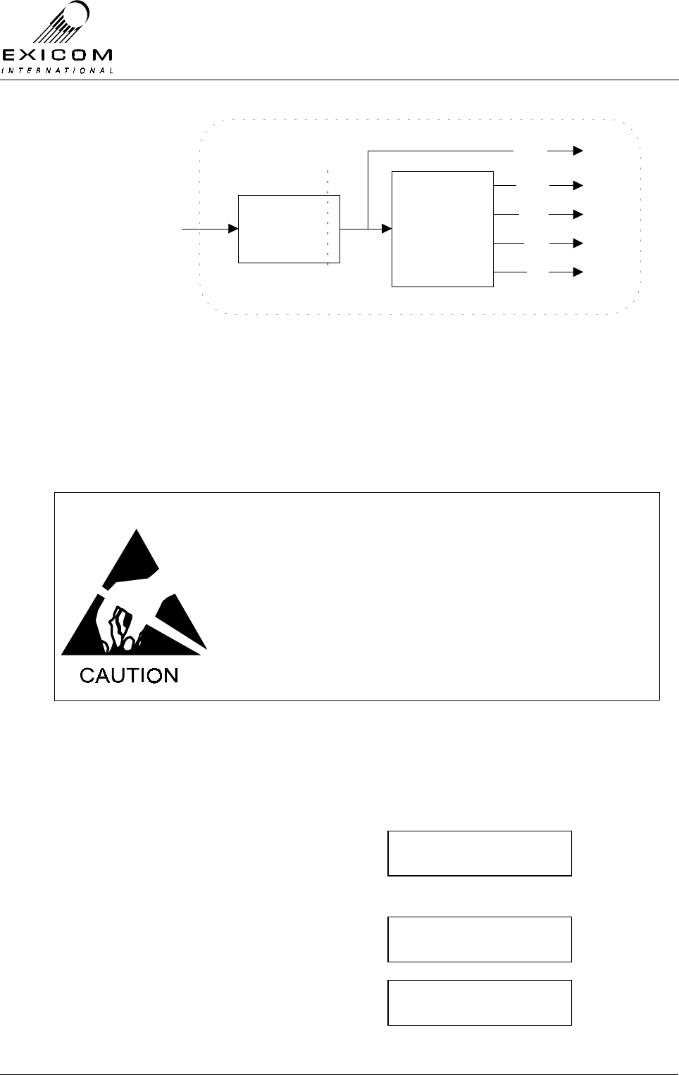
EX7100 Technical Manual - Module Descriptions
©1999 Exicom Technologies (1996) Ltd 7-4 Issue 3 - May 2001
DC Input
From Rear
Panel
Forward
Converter
Isolation
Barrier
Flyback
Converter
+15V
-15V
+5V
-5V
+24V
Figure 7.4: Power Supply Block Diagram
The PSU Measurement Board connected to the Power Supply provides various metering
functions via the terminal’s front panel display (Refer to Section 7.2.2 for details). This is
calibrated to the Power Supply and is considered an integral part of the Power Supply.
7.2.2 Testing and Fault Diagnosis
Note: Refer to Section 5 “Troubleshooting the EX7100” before reading this Section.
The module contains semi-conductor components that are
sensitive to electrostatic damage.
Electrostatic sensitive devices should only be stored and
transported inside electrically conductive static shielding
bags. Fault finding and module replacement must be
performed at “electrostatically safe work stations” where the
work bench surface; soldering iron and the operator are all
earthed to prevent the build up of harmful electrostatic
charges.
General
Front panel diagnostics are available to measure the power supply’s input and output
voltages, and the input current.
To access the PSU Monitoring from idle:
1) From idle, press ‘Enter’
Use the arrow keys to enter the First
Level password ‘1111’ and then press
‘Enter’.
2) Use the up and down arrows until the →
→→
→ is
next to PSU Monitoring and then press
‘Enter’
3) Use the up and down arrows to position
the →
→→
→ next to the required parameter and
then press ‘Enter’ to view
framer
→psu monitoring
+5 VDC rail
→-5 VDC Rail
Password ∗ ∗ 1 ∗
↑
EX7100 Technical Manual - Module Descriptions
©1999 Exicom Technologies (1996) Ltd 7-5 Issue 3 - May 2001
4) Press the ‘Escape’ key to back out of the
menu system.
The power supply can be considered to be operating satisfactorily if the supply rails are
within the ranges specified within Table 7.1 below.
Front Panel Measurement Typical Reading Range
Input DC Voltage 10.8 to 30V (LV variant), 30 to 60V (HV variant)
+24 Volt Rail 22.8 to 25.2V
+15 Volt Rail 14 to 16V
-15 Volt Rail -14 to -16V
+5 Volt Rail 4.8 to 5.2V
-5 Volt Rail -4.7 to -5.3V
Input Current Up to: 9A (LV variant), 3A (HV variant)
Table 7.1: Typical Power Supply Measurement Ranges
If the display is not operating or the power supply rails are not within the expected
voltage, follow the steps outlined in Figure 7.5 overleaf.
Accessing the Power Supply
To gain service access to the power supply module, remove the bottom cover of the
terminal as described in Section 6.1.
Before commencing cover removal, switch the rear panel power
switch off AND isolate the fused supply to the unit. Check that
electrolytic capacitors are discharged before proceeding.
Diagnosis
With the unit de-powered, check the power supply visually for signs of damage such as
burnt tracks, or components. If no damage is apparent, apply power to the terminal and
check the voltages in Table 7.2.
Note: Measurements should be made with an isolated digital multi-meter to prevent the
possibility of injury to servicing personnel or damage to the terminal.
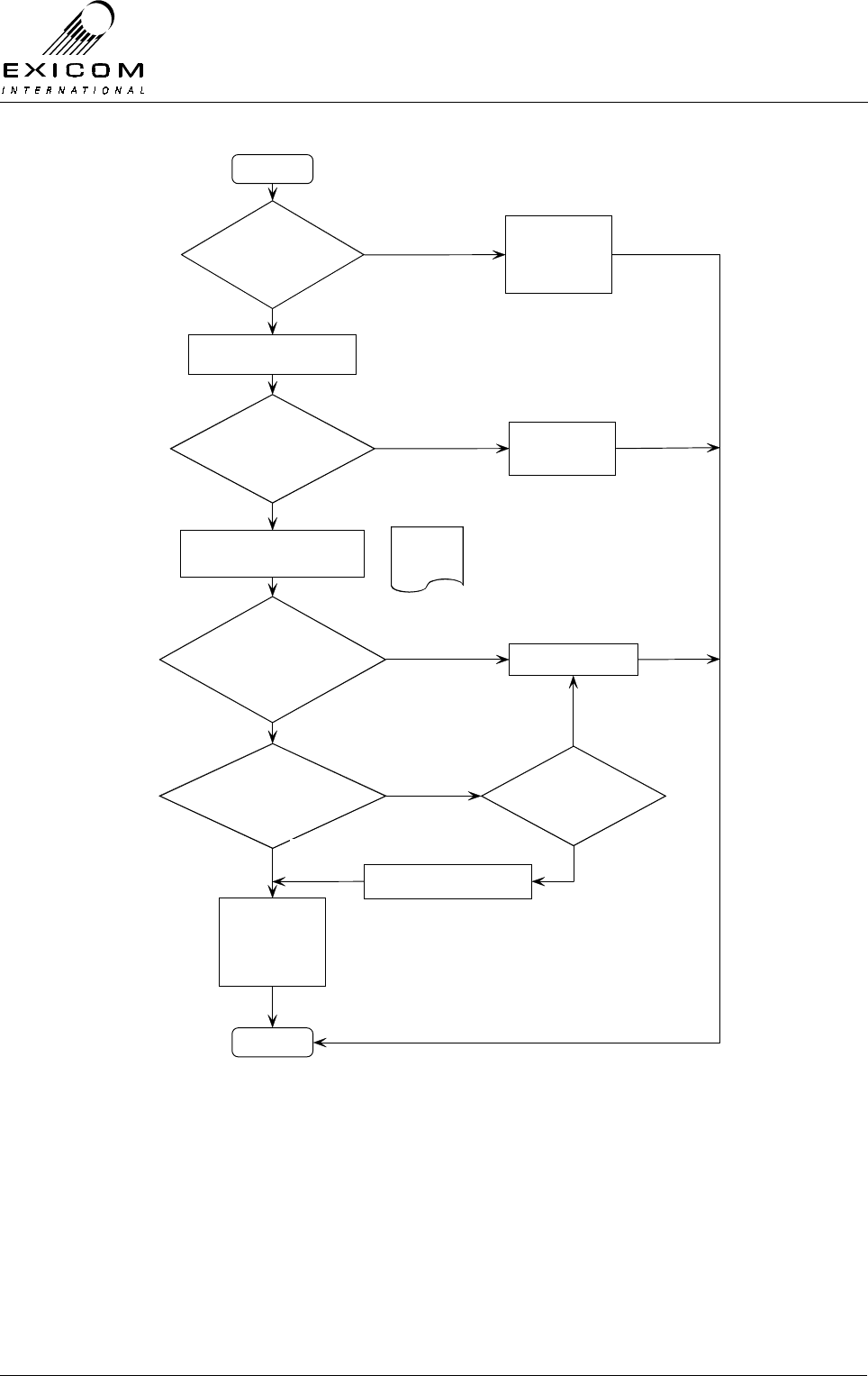
EX7100 Technical Manual - Module Descriptions
©1999 Exicom Technologies (1996) Ltd 7-6 Issue 3 - May 2001
Figure 7.5: Power Supply Fault Diagnostic Tree
Begin
DC i/p present
on Terminal
Rear Panel?
Check DC i/p
supply, external
Fuse, Wiring &
Connections
Switch on EX7100 Terminal
PSU Meter
Readings ok as
per Table 7.1?
PSU Module
appears to be
fault-free
Remove EX7100 Bottom Cover
Refer to
Caution
notes
Does internal Relay
operate with Rear
Panel Switch?
Replace PSU module
Voltages on all
internal Fuses
ok?
Any/all internal
Fuses blown?
PSU appears
fault-free,
Suspect that
another Module
is faulty
Yes
No
Yes
No
No
Yes
No
No
Yes
Replace any blown Fuses
Yes
Finish

EX7100 Technical Manual - Module Descriptions
©1999 Exicom Technologies (1996) Ltd 7-7 Issue 3 - May 2001
Test
Number Fuse
Rating Positive Probe Negative Probe Expected Voltage
1 TB1 +ve terminal. TB1 -ve terminal. Input voltage ± 0.5V.
2 10 A Fuse F1, both ends. Chassis Ground 22.8 to 25.2V.
3 2 A Fuse F2, both ends. Chassis Ground 14 to 16V.
4 1 A Fuse F3, both ends. Chassis Ground -14 to -16V.
5 5 A Fuse F4, both ends. Chassis Ground 4.8 to 5.2V.
6 250 mA Fuse F5, both ends. Chassis Ground -4.7 to -5.3V.
Table 7.2: Typical Power Supply Test Point Voltages
7.2.3 Alignment
The Power Supply requires no alignment and has no user adjustments.
Two potentiometers are provided: RV301 & RV302. They are factory set to the required
under-voltage and over-voltage shut down thresholds and should not be adjusted.
The PSU Measurement board has factory set metering coefficients. These cannot be
adjusted in the field.
7.2.4 Module Replacement Procedure
1. Isolate the EX7100 Terminal from the incoming DC supply by removing the DC input
wires from the rear panel terminal block.
2. Remove the bottom cover as described in Section 6.1.
3. Note the connector positions and the way that the cables are run (it is important that
all cables are replaced as they were initially run before the module replacement
procedure).
4. Disconnect the remote on/off switch loom by unplugging SK301. Remove the wiring
loom plug from PL1 and remove the cable from SK6.
5. Loosen the screws of the terminal block TB1 and remove the DC input wires.
Caution: Remove the six ferrite beads (two per wire) and keep in a safe place for
future replacement.
6. Check, using a multimeter, placed between the earth (on TB1) and the fuse carriers
on the PCB, that the filter capacitors have safely discharged.
7. Remove the nine M3 screws and bushes from the heat-sink mounted
semiconductors. Keep them in a safe place.
8. Remove the six M4 screws and washers holding the PCB and keep them in a safe
place. Carefully lift the PCB out of its housing. Do not carry the PCB by the projecting
semiconductors. The PCB can be safely carried by grasping T1 (the largest
transformer) or by holding it by the edges of the board.

EX7100 Technical Manual - Module Descriptions
©1999 Exicom Technologies (1996) Ltd 7-8 Issue 3 - May 2001
9. Remove the thermal pads and the insulating bushes and discard them. Inspect the
new pads and bushes carefully for any foreign matter. Small specks of dirt or metal
filings can cause the pad to be punctured when the semiconductors are clamped
down.
10. Carefully remove all foreign matter from the mating surfaces of the new Power
Supply’s semiconductors and the heat-sink contact area.
11. Align new pads with the holes in the heat-sink contact area. Place the new power
supply PCB in its cavity and align the board with its mounting holes. Replace the nine
semiconductor mounting screws and bushes. Do not fully tighten the screws.
12. Replace the six M4 PCB mounting screws and washers. Tighten the screws carefully
(do not over tighten as this can strip the internal screw threads). Tighten the
semiconductor mounting screws.
13. Using a multimeter, measure the resistance from the tab of each semiconductor to
the aluminium casting. All readings should be more than 400Ω (ensure that PL1 is
not plugged in when measuring). If any reading is lower, remove the heat-sink
components and check them all carefully for the cause of the short circuit. Caution:
do not proceed with the installation until this insulation test has been passed
successfully or the power supply will be damaged.
14. Replace the six ferrite beads (two per wire) on the main power cables and insert into
terminal block TB1. Ensure that the polarity is correct. Carefully tighten the screws of
the terminal block.
15. Re-connect the cable loom plug into PL1 and the cable into connector SK6.
16. Re-connect the remote on/off switch loom to SK301. Ensure that all cables are run as
they were prior to removal.
17. Inspect the EX7100 terminal to ensure that it is free of foreign material. Remove and
clean as required.
18. Connect the antenna to the terminal. Check the external DC supply fuse, to ensure it
is not blown and replace if required (refer to Section 2.6.1 for fuse types and ratings)
19. Apply power to the EX7100 rear panel and switch the terminal on. Measure the
output rails with a multimeter and verify that they are all within the specifications as
detailed in Table 7.1.
20. Replace the bottom cover, taking care to tighten every screw. No screws should be
left over at the end of the job.
21. Re-install the EX7100 into its rack and re-connect all necessary power, signalling and
antenna cabling.
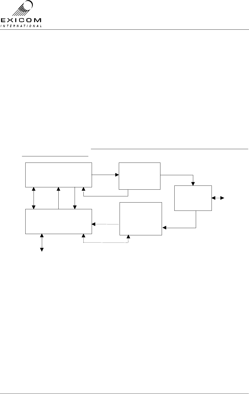
EX7100 Technical Manual - Module Descriptions
©1999 Exicom Technologies (1996) Ltd 7-9 Issue 3 - May 2001
7.3 VHF Transmitter Module Type 8027
7.3.1 General
The VHF Transmitter module accepts data from the Modem Controller module Type 2966
(via the VHF Receiver module Type 8029). This data is filtered, modulated with a locally
generated carrier, amplified and then filtered again ready for amplification by the VHF RF
Power Amplifier Module (PA) Type 8028.
A microcontroller on the Transmitter Module provides control and metering for the
Transmitter, PA, Receiver and Receiver Front-End (FE). The microcontroller on the
Transmitter module also stores configuration information for the Transmitter, Receiver
and RF PA modules.
Figure 7.6 below shows the connections between the RF modules and the
Modem/Controller module. This diagram should be referred to when reading the VHF RF
module sections following.
Transmitter
Module
Receiver
Module
RF PA
Module
Receiver
Front End (FE)
Module
Duplex Filter
(Duplexer)
PL103
Modem/Controller
Data & Comms
Rx RF
Tx RF
Tx Drive
RF
Rx RF
Antenna
Data & Comms
W102
PL101
PL108
W101
Metering
Metering AGC
AGC, Control & Metering
PL102
SK102 SK101
PL100
Figure 7.6: VHF RF Module Connection Block Diagram

EX7100 Technical Manual - Module Descriptions
©1999 Exicom Technologies (1996) Ltd 7-10 Issue 3 - May 2001
Figure 7.7: VHF Transmitter Module in Place within an EX7100 Terminal
7.3.2 Testing and Fault Diagnosis
General
Note: Refer to Section 5 “Troubleshooting the EX7100” before reading this Section.
The Transmitter module provides control to the Receiver module, the Receiver Front-End
module and the Transmitter RF Power Amplifier. It collects measurements from all of
these modules and interacts with the Modem/Controller module.
For this reason, a faulty Transmitter module may cause symptoms that appear elsewhere
while faults elsewhere may cause symptoms to appear at the Transmitter module.
The module contains semi-conductor components that are
sensitive to electrostatic damage.
Electrostatic sensitive devices should only be stored and
transported inside electrically conductive static shielding
bags. Fault finding and module replacement must be
performed at “electrostatically safe work stations” where the
work bench surface; soldering iron and the operator are all
earthed to prevent the build up of harmful electrostatic
charges.
The RF Power Amplifier module must not be run without a
50Ω load on its output. Failure to meet this condition may
damage the amplifier.

EX7100 Technical Manual - Module Descriptions
©1999 Exicom Technologies (1996) Ltd 7-11 Issue 3 - May 2001
The RF devices used in the Power Amplifier module may
contain beryllium dioxide. These devices must not be broken,
ground, hammered or tampered with in any way, and should
be disposed of in a safe manner as specified in local
environmental and safety legislation. If safe disposal is a
problem, they should be sealed in an appropriate container
and returned to Exicom for disposal. In this case, it is the
senders’ responsibility to ensure that all precautions are
taken to ensure safe delivery to Exicom.
Accessing the Transmitter Module
To gain service access to the Transmitter module, remove the bottom cover as per
Section 6.1.
Diagnosis
With the unit de-powered, check the Transmitter module visually for signs of damage
such as burnt tracks or components. Check that all connectors are fully mated and that
all socketed ICs are fully home. If no damage is apparent, apply power and follow the
steps outlined in Figure 7.8.

EX7100 Technical Manual - Module Descriptions
©1999 Exicom Technologies (1996) Ltd 7-12 Issue 3 - May 2001
Figure 7.8: VHF Transmitter Module Fault Diagnostic Tree
Begin
Module RF output on
correct frequency &
at correct level?
Output Filter
correctly
tuned?
Pow er, Tx
Temperature &
VSWR
measurements ok?
Tune Transmitter
output
Yes
No
No
No
Suspect that
Transmitter module is
faulty
Yes
Replace Transmitter
module
Caution:
Antenna
output mus t be
terminated in 50 Ohms
Yes
Suspect that
Transmitter module is
faulty
Replace Transmitter
module
Transmitter module
appears to be fault-free,
suspect that another
Module is faulty
Finis h

EX7100 Technical Manual - Module Descriptions
©1999 Exicom Technologies (1996) Ltd 7-13 Issue 3 - May 2001
7.3.3 Alignment
Re-tuning Of the VHF Transmitter Module
If the frequency of the Transmitter module is to be changed by more than 250kHz from its
tuned frequency, the transmit filter will require adjustment as follows:
1. Remove the bottom cover, disconnect PL108 from the Transmitter module, and feed
this to the RF input of a scalar network analyser (or spectrum analyser with tracking
generator).
2. Set the analyser’s tracking generator output to –10dBm and feed it into the test
socket PL701.
3. Apply power to the terminal. Turn the Transmitter off by setting the terminal’s
operating mode to ‘On-Demand’. (Refer to Section 3 for details).
4. Adjust the Tx output bandpass filter so that the response is symmetrical about the
new centre frequency, and is >33 dB down at +/- 5 MHz from the centre frequency.
The bandpass filter is made up of five tuneable inductors inside an aluminium block.
Access to these inductors is through five small holes in the block. Tune the filter
using a suitable hex tuning tool, starting from the centre inductor and working
outwards. This procedure may need to be repeated several times. Be careful not to
bottom the cores at either end of travel as the cores will break.
Note: The Duplexer module must also be adjusted to suit the new centre frequency
(refer to Section 7.9.3 for tuning details). Failure to adjust the Duplexer module at
this point may result in damage to the PA module
5. Disconnect the analyser and reconnect the PA’s coax to PL108.
6. Set the new the transmit frequency via the front panel as per Section 3.
7. Check that the VCO Loop Volts measurement on TP301 (or front panel) is within the
limits 4 to 5 Volts. If necessary, reset this by adjusting the VCO trimmer capacitor
through the access hole in the square aluminium block.
Carrier Null
The carrier null should be stable over the long term. If bit error rates climb, carrier
leakage could be the problem.
1. Put the terminal into “Align Mode” with DSBSC mode selected Refer to Section 4.5.1.
(Not to be confused with “Antenna Align Mode” as described in Section 2.11.2)
2. Connect a spectrum analyser via an attenuator to the transmitter’s output to observe
the sampled spectrum.
3. Using a narrow resolution bandwidth observe the on-channel carrier’s level. This
reading should be at least 40 dB (preferably 50 dB) below the two adjacent tones, if
this is not the case, re-null using RV501 and RV502.

EX7100 Technical Manual - Module Descriptions
©1999 Exicom Technologies (1996) Ltd 7-14 Issue 3 - May 2001
7.3.4 VHF Transmitter Module Replacement Procedure
1. Remove the bottom cover as described in Section 6.1.
2. Note the connector positions and the way that the cables are run (it is important that
all cables are replaced as they were initially run before the module replacement
procedure)
Remove the following connectors from the Transmitter PCB:
PL101, PL103, PL104, PL105 and PL108.
Remove connector PL101 from the Receiver PCB:
(This connector is attached to W102 on the Transmitter PCB)
3. Remove the six M3 screws and washers that retain the module. Keep the screws in a
safe place.
4. Carefully position the new Transmitter PCB into the casting taking care not to flex the
PCB as this can cause damage to the surface mounted components. Replace the six
M3 PCB mounting screws and washers. Tighten the screws carefully.
5. Reconnect connectors PL101, PL103, PL104, PL105 and PL108 on the Transmitter
PCB and PL101 on the Receiver PCB; ensure that all cables are run as they were
prior to removal.
6. Inspect the EX7100 terminal to ensure that it is free of foreign material. Remove and
clean as required.
7. Connect the antenna to the terminal. (Caution: do not proceed until this is done to
avoid damage to the PA module). Apply power to the EX7100 rear panel and switch
the terminal on.
8. If necessary, retune the Transmitter output filter (refer to Section 7.3.3 above).
9. Set the Transmitter, Receiver and RF Power Amplifier module configuration variables
as these are all carried by the microcontroller on the Transmitter module (refer to
Section 3 as required).
10. Return to normal operating mode and check that the link is correctly established. If
not refer to Section 7.3.2 above and Section 5 “Troubleshooting” as required.
11. Replace the bottom cover, taking care to tighten every screw. No screws should be
left over at the end of the job
12. Re-install the EX7100 back into its rack and re-connect all necessary power,
signalling and antenna cabling.

EX7100 Technical Manual - Module Descriptions
©1999 Exicom Technologies (1996) Ltd 7-15 Issue 3 - May 2001
7.4 UHF Transmitter Module Type 8053
7.4.1 General
The Transmitter module accepts data from the Modem Controller module Type 2966 (via
the Receiver module Type 8054). This data is filtered, modulated with a locally generated
carrier, amplified and then filtered again ready for amplification by the RF Power Amplifier
Module (PA) Type 8048
A microcontroller on the Type 8044 CPU sub-module provides control and metering for
the Transmitter, PA, Receiver and Receiver Front-End (FE). The microcontroller also
stores configuration information for the Transmitter, Receiver and RF PA modules.
Figure 7.9 below shows the connections between the RF modules and the
Modem/Controller module. This diagram should be referred to when reading the UHF RF
module sections following
Transmitter
Module
Receiver
Module
RF PA
Module
Receiver
Front End (FE)
Module
Terminal Rear Panel
Rx RF
Tx RF
Tx Drive
RF
Rx RF
Antenna
Tx RF out
W101
Metering
AGC, Control & Metering
PL102
SK102 SK101
J101
Duplex Filter
(Duplexer)
Figure 7.9: UHF RF Module Connection Block Diagram
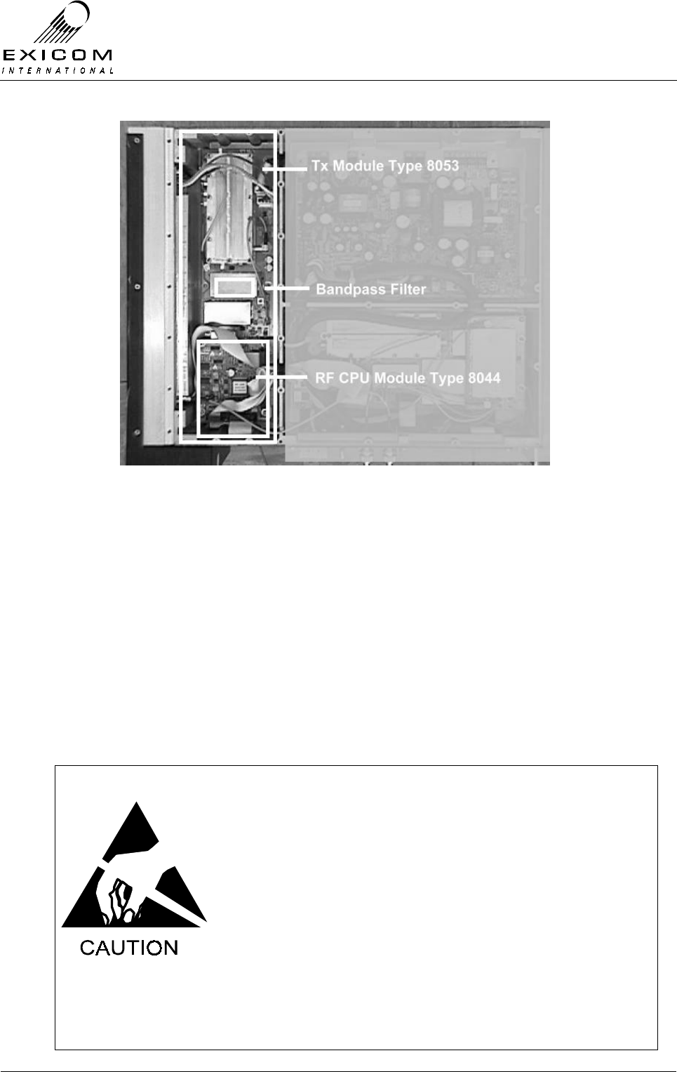
EX7100 Technical Manual - Module Descriptions
©1999 Exicom Technologies (1996) Ltd 7-16 Issue 3 - May 2001
Figure 7.10: UHF Transmitter Module in Place within an EX7100 Terminal
7.4.2 Testing and Fault Diagnosis
General
Note: Refer to Section 5 “Troubleshooting the EX7100” before reading this Section.
The Transmitter CPU sub-module provides control to the Transmitter module, the
Receiver module, the Receiver Front-End module and the Transmitter RF Power
Amplifier. It collects measurements from all of these modules and interacts with the
Modem/Controller module.
For this reason, a faulty Transmitter CPU module may cause symptoms that appear
elsewhere while faults elsewhere may cause symptoms to appear at the Transmitter
module.
The module contains semi-conductor components that are
sensitive to electrostatic damage.
Electrostatic sensitive devices should only be stored and
transported inside electrically conductive static shielding
bags. Fault finding and module replacement must be
performed at “electrostatically safe work stations” where the
work bench surface; soldering iron and the operator are all
earthed to prevent the build up of harmful electrostatic
charges.
The RF Power Amplifier module must not be run without a
50Ω load on its output. Failure to meet this condition may
damage the amplifier.

EX7100 Technical Manual - Module Descriptions
©1999 Exicom Technologies (1996) Ltd 7-17 Issue 3 - May 2001
The RF devices used in the Power Amplifier module may
contain beryllium dioxide. These devices must not be broken,
ground, hammered or tampered with in any way, and should
be disposed of in a safe manner as specified in local
environmental and safety legislation. If safe disposal is a
problem, they should be sealed in an appropriate container
and returned to Exicom for disposal. In this case, it is the
senders’ responsibility to ensure that all precautions are
taken to ensure safe delivery to Exicom.
Accessing the Transmitter Module
To gain service access to the Transmitter module, remove the bottom cover as per
Section 6.1.
Diagnosis
With the unit de-powered, check the Transmitter module visually for signs of damage
such as burnt tracks or components. Check that all connectors are fully mated and that
all socketed ICs are fully home. If no damage is apparent, apply power and follow the
steps outlined in Figure 7.11.
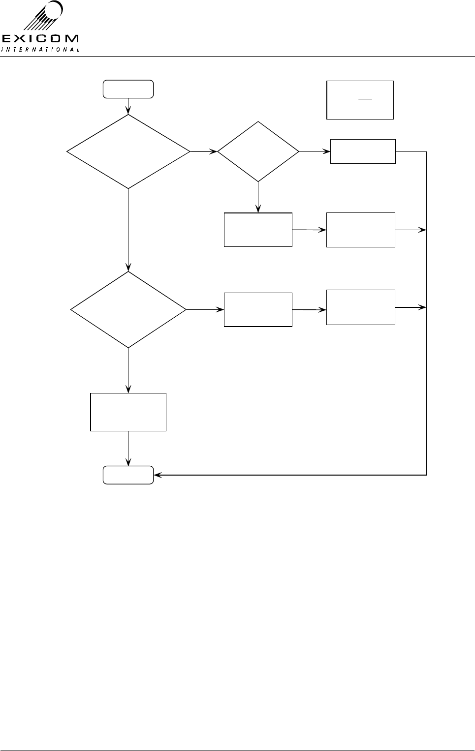
EX7100 Technical Manual - Module Descriptions
©1999 Exicom Technologies (1996) Ltd 7-18 Issue 3 - May 2001
Figure 7.11: UHF Transmitter Module Fault Diagnostic Tree
Begin
Module RF output on
correct frequency &
at correct level?
Output Filter
correctly
tuned?
Pow er, Tx
Temperature &
VSWR
measurements ok?
Tune Transmitter
output
Yes
No
No
No
Suspect that
Transmitter module is
faulty
Yes
Replace Transmitter
module
Caution:
Antenna
output mus t be
terminated in 50 Ohms
Yes
Suspect that
Transmitter module is
faulty
Replace Transmitter
module
Transmitter module
appears to be fault-free,
suspect that another
Module is faulty
Finis h
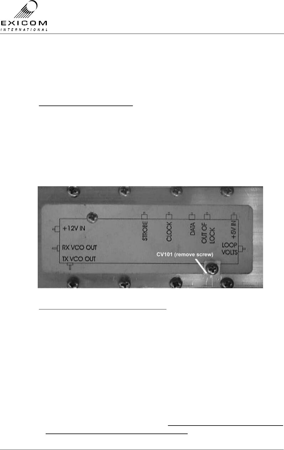
EX7100 Technical Manual - Module Descriptions
©1999 Exicom Technologies (1996) Ltd 7-19 Issue 3 - May 2001
7.4.3 Alignment
Re-tuning Of the Transmitter Module
If the frequency of the Transmitter module is to be changed by more than ±2.5 MHz from
its tuned frequency, the following checks or adjustments are required:
Checking the VCO Loop Voltage
1. Set the new Transmit frequency via the front panel as per Section 3.
2. Remove the bottom cover and refer to Figure 7.12 below to identify the location of
the Loop Volts output feed-through capacitor in the local oscillator module. Check
with a digital multi-meter (DMM) that the VCO Loop Volts measurement is within the
range of 3 to 4 Volts DC.
If necessary, reset this by adjusting VCO trimmer capacitor CV101 as indicated in
Figure 7.12 below. (It will be necessary to remove the screw in the aluminium block
to access the trimmer. Always replace this screw after adjustment).
Figure 7.12: Location of Loop Volts adjustment CV101
Adjustment of the transmitter bandpass filter
1. With the bottom cover removed, disconnect PL103 (to PA Module) and remove the
“Tx RF out” SMB lead from socket PL107. Connect the RF input of a Spectrum
Analyser with Tracking Generator or scalar network analyser to socket PL107.
2. Set the analyser’s tracking generator output to –10dBm. Feed the tracking generator
output into SK303.
3. Apply power to the terminal. Turn the Transmitter off by setting the terminal’s
operating mode to ‘On-Demand’. (Refer to Section 3 for details).
4. Adjust the two helicals within the output filter to achieve a suitable flat passband at
the desired frequency. The passband should be approximately 5.0 MHz wide and flat
within +/- 2.0 dB across that band.
Note: The Duplexer module must also be adjusted to suit the new centre frequency
(refer to Section 7.10.3 for tuning details). Failure to adjust the Duplexer module at
this point may result in damage to the PA module

EX7100 Technical Manual - Module Descriptions
©1999 Exicom Technologies (1996) Ltd 7-20 Issue 3 - May 2001
5. Disconnect the analyser input and output from the PCB and reconnect for normal
operation.
Carrier Null
The carrier null should be stable over the long term. If bit error rates climb, carrier
leakage could be the problem.
1. Put the terminal into “Align Mode” with DSBSC mode selected. Refer to Section 4.5.1
(Not to be confused with “Antenna Align Mode” as described in Section 2.11.2)
2. Connect a spectrum analyser via an attenuator to the transmitter’s output to observe
the sampled spectrum.
3. Using a narrow resolution bandwidth observe the on-channel carrier’s level. This
reading should be at least 40 dB (preferably 55 dB) below the two adjacent tones. If
this is not the case, re-null using the two adjustment pots RV201 and RV202 (see
note below) on the main Tx PCB. The adjustment pot RV203 adjusts the I/Q bias
voltage and under normal circumstances will not need adjustment. If adjustment is
necessary, the voltage can be monitored on test point TP201 and should be 1.7V ±
20mV. Upon adjustment of this voltage, re-check the carrier null.
Note: The RF CPU will have to be moved out of the way (but not disconnected) in
order to access the adjustment pots. Do so by removing the four mounting screws
and easing the module out of the way.
7.4.4 UHF Transmitter Module Replacement Procedure
Note: It is necessary to remove the CPU sub-module prior to replacing the Transmitter
module, however, the CPU sub-module can be replaced without removal of the
Transmitter module.
Replacement of the Type 8044 Sub-Module
1. Remove the bottom cover as described in Section 6.1.
2. Note the connector positions and the way that the cables are run (it is important that
all cables are replaced as they were initially run before the module replacement
procedure)
Remove the following connectors from the CPU sub-module PCB:
PL102, PL103 and PL104
Remove connector PL101 from the Receiver PCB:
(This connector is attached to W101 on the CPU sub-module PCB)
3. Remove the four M3 screws and washers that retain the CPU sub-module. Keep the
screws in a safe place.
4. Position the new CPU sub-module and replace the four M3 screws and washers.
Tighten the screws carefully
5. Reconnect connectors PL102, PL103 and PL104 on the CPU sub-module and
connector PL101 on the Receiver PCB; ensure that all cables are run as they were
prior to removal.

EX7100 Technical Manual - Module Descriptions
©1999 Exicom Technologies (1996) Ltd 7-21 Issue 3 - May 2001
6. Inspect the EX7100 terminal to ensure that it is free of foreign material. Remove and
clean as required.
7. Connect the antenna to the terminal. (Caution: do not proceed until this is done to
avoid damage to the PA module). Apply power to the EX7100 rear panel and switch
the terminal on.
8. If necessary, retune the Transmitter output filter (refer to Section 7.4.3 above).
9. Set the Transmitter, Receiver and RF Power Amplifier module configuration variables
as these are all carried by the microcontroller on the Transmitter module (refer to
Section 3 as required).
10. Return to normal operating mode and check that the link is correctly established. If
not refer to Section 7.4.2 above and Section 5 “Troubleshooting” as required.
11. Replace the bottom cover, taking care to tighten every screw. No screws should be
left over at the end of the job
12. Re-install the EX7100 into its rack and re-connect all necessary power, signalling and
antenna cabling.

EX7100 Technical Manual - Module Descriptions
©1999 Exicom Technologies (1996) Ltd 7-22 Issue 3 - May 2001
Removal of the Transmitter module
1. Remove the CPU sub-module as previously described.
Remove the following connectors from the Transmitter PCB:
PL101 (DC input), PL103 (connection to the PA), and PL107 (SMB connector, “Tx
RF out).
2. Remove the three stand-offs and the three M3 screws and washers that hold the
Transmitter module into the casting, then remove the Transmitter module, keeping
all fastenings in a safe place.
3. Carefully position the new Transmitter PCB into the casting taking care not to flex the
PCB as this can cause damage to the surface mounted components. Replace the
stand-offs and M3 PCB mounting screws and washers. Tighten the screws carefully.
4. Replace the CPU sub-module as previously described and reconnect connectors
PL101, PL103 and PL107 on the Transmitter module. Ensure that all cables are run
as they were prior to removal.
5. Inspect the EX7100 terminal to ensure that it is free of foreign material. Remove and
clean as required.
6. Connect the antenna to the terminal. (Caution: do not proceed until this is done to
avoid damage to the PA module). Apply power to the EX7100 rear panel and switch
the terminal on.
7. If necessary, retune the Transmitter output filter (refer to Section 7.4.3 above).
8. Set the Transmitter, Receiver and RF Power Amplifier module configuration variables
(refer to Section 3 as required).
9. Return to normal operating mode and check that the link is correctly established. If
not refer to Section 7.4.2 above and Section 5 “Troubleshooting” as required.
10. Replace the bottom cover, taking care to tighten every screw. No screws should be
left over at the end of the job.
11. Re-install the EX7100 back into its rack and re-connect all necessary power,
signalling and antenna cabling.
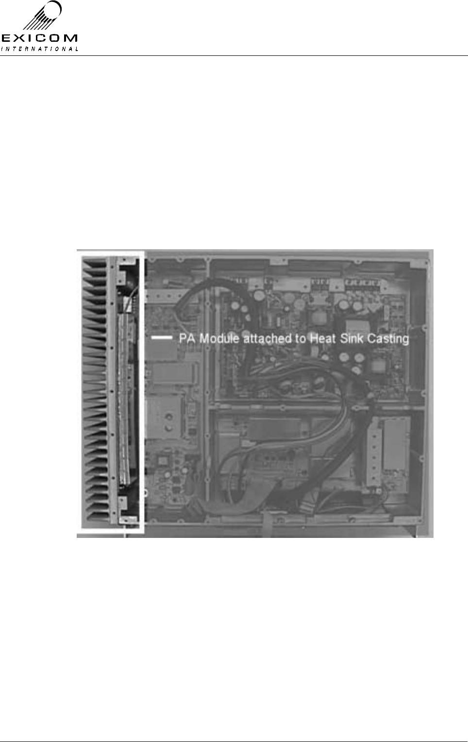
EX7100 Technical Manual - Module Descriptions
©1999 Exicom Technologies (1996) Ltd 7-23 Issue 3 - May 2001
7.5 VHF RF Power Amplifier Module Type 8028
7.5.1 General
The VHF RF Power Amplifier module is driven by a modulated signal on the required RF
frequency by the VHF Transmitter module Type 8027. Refer to Figure 7.6 “VHF RF
Connection Diagram” for details.
The Transmitter module maintains a constant RF output power adjusting the drive level
as necessary.
Various metering outputs, including forward power, reverse power and heat sink
temperature, are monitored by the Transmitter module (refer to Section 4.2.1).
Figure 7.13: VHF RF Power Amplifier Module in Place within an EX7100 Terminal

EX7100 Technical Manual - Module Descriptions
©1999 Exicom Technologies (1996) Ltd 7-24 Issue 3 - May 2001
7.5.2 Testing and Fault Diagnosis
Note: Refer to Section 5 “Troubleshooting the EX7100” before reading this Section.
The module contains semi-conductor components that are
sensitive to electrostatic damage.
Electrostatic sensitive devices should only be stored and
transported inside electrically conductive static shielding
bags. Fault finding and module replacement must be
performed at “electrostatically safe work stations” where the
work bench surface, soldering iron and the operator are all
earthed to prevent the build up of harmful electrostatic
charges.
The RF Power Amplifier module must not be run without a
50Ω load on its output. Failure to meet this condition may
damage the amplifier.
The RF devices used in the Power Amplifier module may
contain beryllium dioxide. These devices must not be broken,
ground, hammered or tampered with in any way, and should
be disposed of in a safe manner as specified in local
environmental and safety legislation. If safe disposal is a
problem, they should be sealed in an appropriate container
and returned to Exicom for disposal. In this case, it is the
senders’ responsibility to ensure that all precautions are
taken to ensure safe delivery to Exicom.
VHF RF Power Amplifier Module Testing
Module DC Input Power Measurement
1. Remove the bottom cover of the terminal as described in Section 6.1.
2. The power supply provided to the RF Power Amplifier (connected at PL104) can be
measured at PL103 on the Transmitter PCB by directly accessing the pins with a
multimeter. Refer to Table 7.3 below for expected voltages on PL103
Pin Number on PL103 Expected Voltage
1 Ground
2 +14 to 16 V
3 +14 to 16 V
4 +22.8 to 25.4 V
Table 7.3: Power Amplifier Module DC Input Voltages

EX7100 Technical Manual - Module Descriptions
©1999 Exicom Technologies (1996) Ltd 7-25 Issue 3 - May 2001
RF Output Power Measurement
Note: Without available RF test equipment, RF Power Amplifier faults can only be
confirmed by substitution of the module.
If an RF signal generator, RF power meter and suitable test load are available, it is
possible to undertake a simple functional test of the RF Power Amplifier module. Refer to
Figure 7.14 below for equipment connection details.
Signal
Generator
-20 to -10dBm
RF Power
Amplifier Module
Under Test
RF Power
Meter (Bird
or similar)
50Ω 10
Watt Load
RF Input
PL100
RF Output
PL102
Figure 7.14: VHF PA Module Test set-up
1. Connect the cable attached to PL108 (Transmitter PCB) to the output of the signal
generator (set to the desired transmit frequency at -20 dBm output level).
2. Connect the RF power meter to PL102 (RF output).
3. The RF Power Amplifier should be able to produce a reading on the RF power meter
of approximately 6.5 Watts when the signal level from the signal generator is slowly
increased from –20 to –10dBm.
If this is the case, the RF Power Amplifier is probably functioning correctly.
Confirm that with approximately 6.5 Watts RF output from the PA module, there is a
forward power reading shown on the LCD of the EX7100 terminal.
Refer to Section 4.2.1 for details of the forward power measurement process.
Note: The front panel LCD reading will not be correct as the terminal is calibrated for a
complex waveform).
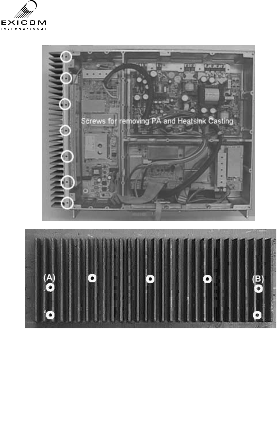
EX7100 Technical Manual - Module Descriptions
©1999 Exicom Technologies (1996) Ltd 7-26 Issue 3 - May 2001
Figure 7.15: Bottom Cover Screws for VHF PA Removal
Figure 7.16: Heat Sink Screws for VHF PA Removal
Note: Screws marked (A) and (B) may not be present if the EX7100 Terminal contains
the VHF Fan Box Type 61-8057-00002 (refer to the supplement at the front of this
Manual for further details)

EX7100 Technical Manual - Module Descriptions
©1999 Exicom Technologies (1996) Ltd 7-27 Issue 3 - May 2001
7.5.3 Alignment
There are no user adjustments available on the RF Power Amplifier module. Specialist
factory test equipment and procedures are required to correctly set up the amplifier.
Module Re-tuning
The RF Power Amplifier module is a broad band device and does not require adjustment.
7.5.4 VHF RF Power Amplifier Replacement Procedure
This procedure covers the replacement of the RF Power Amplifier Module1.
1. Isolate the EX7100 Terminal from the incoming DC Supply by removing the DC input
wires from the rear panel terminal block.
2. Remove the seven screws securing the bottom cover of the terminal to the finned
heat sink casting as per Figure 7.15.
3. Remove the seven cap screws holding the heat sink casting to the main casting as
per Figure 7.16.
4. Carefully ease the heat sink away from the terminal making sure not to damage the
connecting cables. Note the connector positions and the way that the cables are run
(it is important that all cables are replaced as they were initially run before the module
replacement procedure)
5. Remove the Duplexer cable PL102 from the PA PCB, also remove the mating end of
the following connections: PL100 (to PL108 transmitter PCB), PL103 (to PL105
transmitter PCB) and PL104 (to PL103 transmitter PCB).
6. Carefully reconnect the above cables to the new Power Amplifier and position the
new module inside the EX7100 terminal casting.
7. Refit the seven cap screws holding the heat sink casting into the main casting. (Refer
to Figure 7.16)
8. Inspect the EX7100 terminal to ensure that it is free of foreign material. Remove and
clean as required.
9. Replace the seven screws securing the bottom cover of the terminal to the finned
heat sink casting. (Refer to Figure 7.15).
10. Connect the antenna to the terminal. Apply power to the EX7100 rear panel and
switch the terminal on.
11. Return to normal operating mode and check that the link is correctly established. If
not refer to Testing & Fault Diagnosis (Section 7.5.2).
12. Re-install the EX7100 back into its rack and re-connect all necessary power,
signalling and antenna cabling.
1 If the VHF Terminal contains the Fan Box Type 8057, please refer to the supplement at the start of this Manual for
removal details prior to replacing the RF Power Amplifier.

EX7100 Technical Manual - Module Descriptions
©1999 Exicom Technologies (1996) Ltd 7-28 Issue 3 - May 2001
7.6 UHF RF Power Amplifier Module Type 8048
7.6.1 General
The UHF RF Power Amplifier module is driven by a modulated signal on the required RF
frequency by the UHF Transmitter module Type 8053. Refer to Figure 7.9 “UHF RF
Connection Diagram” for details.
The Power Amplifier module maintains a constant gain of 50dB; with RF output power
being adjusted in the transmitter drive stage.
Various metering outputs, including forward power, reverse power and heat sink
temperature, are monitored by the Transmitter module (refer to Section 4.2.1).
The Power Amplifier is a wideband device covering 380-520MHz without manual
retuning.
To assist in cooling, dual fans and an enclosure are fitted over and around the PA
heatsink
Figure 7.17: UHF RF Power Amplifier Module in Place within an EX7100 Terminal
EX7100 Technical Manual - Module Descriptions
©1999 Exicom Technologies (1996) Ltd 7-29 Issue 3 - May 2001
7.6.2 Testing and Fault Diagnosis
Note: Refer to Section 5 “Troubleshooting the EX7100” before reading this Section.
The module contains semi-conductor components that are
sensitive to electrostatic damage.
Electrostatic sensitive devices should only be stored and
transported inside electrically conductive static shielding
bags. Fault finding and module replacement must be
performed at “electrostatically safe work stations” where the
work bench surface, soldering iron and the operator are all
earthed to prevent the build up of harmful electrostatic
charges.
The RF Power Amplifier module must not be run without a
50Ω load on its output. Failure to meet this condition may
damage the amplifier.
The RF devices used in the Power Amplifier module may
contain beryllium dioxide. These devices must not be broken,
ground, hammered or tampered with in any way, and should
be disposed of in a safe manner as specified in local
environmental and safety legislation. If safe disposal is a
problem, they should be sealed in an appropriate container
and returned to Exicom for disposal. In this case, it is the
senders’ responsibility to ensure that all precautions are
taken to ensure safe delivery to Exicom.
UHF RF Power Amplifier Module Testing
Module DC Input Power Measurement
1. Remove the bottom cover of the terminal as described in Section 6.1.
2. Measure the power supply to the RF Power Amplifier module on the Tx PCB with a
multimeter (by directly accessing the pins within PL103). Refer to Table 3.3 below for
expected voltages on PL104.
Pin Number on PL103 Expected Voltage
1 Ground
2 +14 to 16 V
3 +14 to 16 V
4 +22.8 to 25.4 V
Table 7.3: Power Amplifier Module DC Input Voltages
EX7100 Technical Manual - Module Descriptions
©1999 Exicom Technologies (1996) Ltd 7-30 Issue 3 - May 2001
RF Output Power Measurement
Note: Without available RF test equipment, RF Power Amplifier faults can only be
confirmed by substitution of the module.
If an RF signal generator, RF power meter and suitable test load are available, it is
possible to undertake a simple functional test of the RF Power Amplifier module. Refer to
Figure 7.18 below for equipment connection details.
Signal
Generator
-20 to -10dBm
RF Power
Amplifier Module
Under Test
RF Power
Meter (Bird
or similar)
50Ω 10 W
load
RF Input
J101
RF Output
PL102
Figure 7.18: UHF PA Module Test set-up
1. Disconnect the cable attached to “Tx RF out” SMB connector on the Tx PCB, and
reconnect this to the output of the signal generator (set to the desired transmit
frequency at -20 dBm output level).
2. Connect the RF power meter to PL102 (RF output).
3. The RF Power Amplifier should be able to produce a reading on the RF power meter
of approximately 6.5 Watts when the signal level from the signal generator is slowly
increased from –20 to –10dBm.
If this is the case, the RF Power Amplifier is probably functioning correctly.
Confirm that with approximately 6.5 Watts RF output from the PA module, there is a
forward power reading shown on the LCD of the EX7100 terminal.
Refer to Section 4.2.1 for details of the forward power measurement process.
Note: The front panel LCD reading will not be correct as the terminal is calibrated for a
complex waveform).
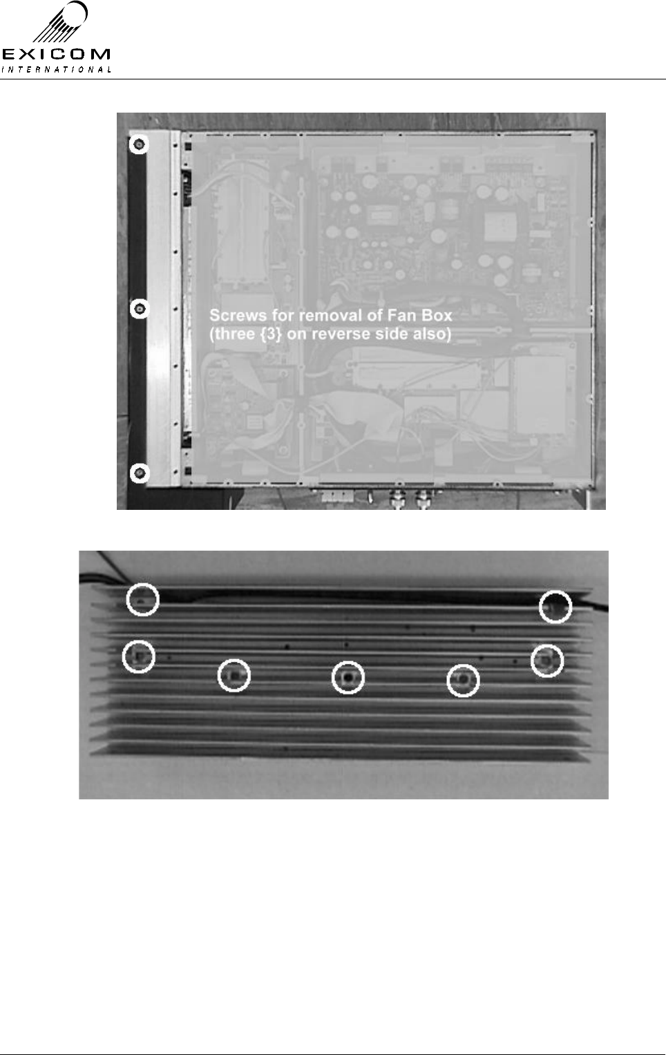
EX7100 Technical Manual - Module Descriptions
©1999 Exicom Technologies (1996) Ltd 7-31 Issue 3 - May 2001
Figure 7.19: Bottom Cover Screws for UHF PA Removal
Figure 7.20: Heat Sink Screws for UHF PA Removal

EX7100 Technical Manual - Module Descriptions
©1999 Exicom Technologies (1996) Ltd 7-32 Issue 3 - May 2001
7.6.3 Alignment
There are no user adjustments available on the RF Power Amplifier module. Specialist
factory test equipment and procedures are required to correctly set up the amplifier.
Module Re-tuning
The RF Power Amplifier module is a broad band device and does not require adjustment.
7.6.4 UHF RF Power Amplifier Replacement Procedure
This procedure covers the replacement of the RF Power Amplifier Module.
Note: Under NO circumstances must the terminal be connected to DC supply without the
Antenna port being terminated. Powering up of the PA without a load will result in
the PA being damaged.
1. Isolate the EX7100 Terminal from the incoming DC Supply by removing the DC input
wires from the rear panel terminal block.
2. Remove the bottom cover of the terminal as per Section 6.1.
3. Remove the six screws securing the cooling fan box assembly (see Figure 7.19) to
the PA heatsink to reveal the heatsink securing screws.
4. Ease the Fan Box away from the PA Heatsink, disconnect Fan control wires from the
terminal block, and then remove the Fan Box. Note the position of wires and the way
that the wires are run.
5. Remove the seven cap screws holding the heat sink casting to the main casting as
per Figure 7.20.
6. Carefully ease the heat sink away from the terminal making sure not to damage the
connecting cables. Note the connector positions and the way that the cables are run
(it is important that all cables are replaced as they were initially run before the
module replacement procedure)
7. Remove the RF cable PL102 from the PA PCB, also remove the mating end of the
following connections: J101 (to “Tx RF out”, transmitter PCB), PL103 (to RF CPU
PCB) and PL104 (to white 4-way connector, transmitter PCB).
8. Carefully reconnect the above cables to the new Power Amplifier and position the
new module inside the EX7100 terminal casting. Refit the seven cap screws holding
the heat sink casting into the main casting. (Refer to Figure 7.20)
9. Reconnect the Fan control wires as noted in 4. above and position the Fan Box over
the PA Heatsink. Refit the six screws securing the Fan Box to the PA Heatsink
(Refer to Figure 7.19).
10. Inspect the EX7100 terminal to ensure that it is free of foreign material. Remove and
clean as required.
11. Refit the bottom cover of the terminal as per Section 6.1.
12. Connect the antenna to the terminal. Apply power to the EX7100 rear panel and
switch the terminal on.

EX7100 Technical Manual - Module Descriptions
©1999 Exicom Technologies (1996) Ltd 7-33 Issue 3 - May 2001
13. Return to normal operating mode and check that the link is correctly established. If
not refer to Testing & Fault Diagnosis (Section 7.6.2).
14. Re-install the EX7100 back into its rack and re-connect all necessary power,
signalling and antenna cabling.
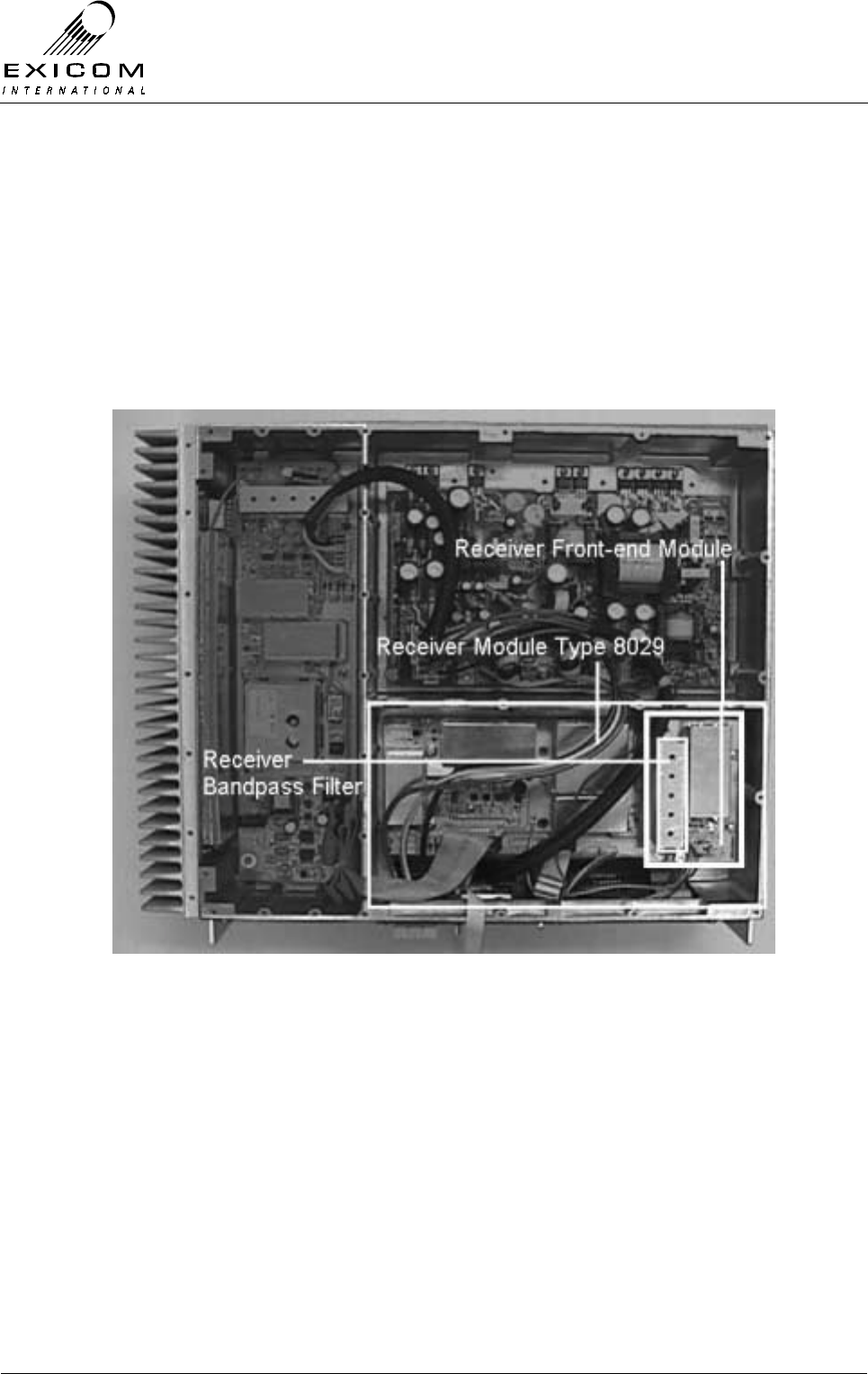
EX7100 Technical Manual - Module Descriptions
©1999 Exicom Technologies (1996) Ltd 7-34 Issue 3 - May 2001
7.7 VHF Receiver Module Type 8029
7.7.1 General
Received RF is passed from the antenna through the Duplexer to the Front End sub-
module Type 8018 where it is filtered and amplified. This RF is applied to the Receiver
module’s RF input, it is then filtered, amplified, mixed and demodulated.
The microcontroller on the Transmitter module provides metering for the receiver,
generates the automatic gain control (AGC) voltages, controls the Receiver module’s
synthesisers and stores receiver configuration information.
Figure 7.21: VHF Receiver Module in Place within Terminal
7.7.2 Testing and Fault Diagnosis
General
Note: Refer to Section 5 “Troubleshooting the EX7100” before reading this section.
The Transmitter module provides control to both the Receiver module and the Receiver
Front-End module (AGC and synthesiser setting) and also collects measurements from
the Receiver modules. An apparent Receiver problem may actually be caused by a fault
with the Transmitter module.

EX7100 Technical Manual - Module Descriptions
©1999 Exicom Technologies (1996) Ltd 7-35 Issue 3 - May 2001
The module contains semi-conductor components that are
sensitive to electrostatic damage.
Electrostatic sensitive devices should only be stored and
transported inside electrically conductive static shielding
bags. Fault finding and module replacement must be
performed at “electrostatically safe work stations” where the
work bench surface, soldering iron and the operator are all
earthed to prevent the build up of harmful electrostatic
charges.
Accessing the VHF Receiver Module
To gain service access to the Receiver module, remove the bottom cover as per Section
6.1.
Diagnosis
With the unit de-powered, check the receiver module visually for signs of damage such
as burnt tracks or components. Check that all connectors are fully mated. If no damage
is apparent, apply power and follow the steps outlined in Figure 7.22 overleaf

EX7100 Technical Manual - Module Descriptions
©1999 Exicom Technologies (1996) Ltd 7-36 Issue 3 - May 2001
Figure 7.22: VHF Receiver Module Fault Diagnostic Tree
Begin
Rec eive
Frequency
correct?
Rec eiver
Front-end tuned
correctly?
Set correct
Receive Frequency
Yes
No
No
Caution:
Antenna
output mus t be
terminated in 50 Ohms
Yes
Tune Front-end filter
RSSI
Measurements
OK?
Finish
Suspect that Receiver
or Transmitter module
is faulty
Receiver module appears
to be fault-free, suspect
that another Module is
faulty
No
Replace Receiver or
Transmitter Module
Yes

EX7100 Technical Manual - Module Descriptions
©1999 Exicom Technologies (1996) Ltd 7-37 Issue 3 - May 2001
7.7.3 Alignment
Module Re-tuning
The main Receiver module should not require any adjustment when being re-channelled.
The Receiver Front-End module Type 8018 requires adjustment of the receiver bandpass
filters.
Note: There are three variants of the Front-End module, one covering 138-148MHz, one
covering 147-162MHz, and the other 159-174MHz.
The front-end bandpass filter requires adjustment when the receiver frequency is being
changed by more than 250kHz from the filter’s previous centre frequency.
1. Set terminal to ‘On-demand’ mode to ensure the transmitter is turned off.
2. Remove the bottom cover as described in Section 6.1; disconnect the coaxes from
SK101 and SK102 on the Receiver Front-End module. Feed the output of SK102 to
the RF input of a scalar network analyser (or spectrum analyser with tracking
generator), with reference amplitude of 0dBm and span of 4MHz/div.
3. Set the RF output of the analyser’s tracking generator level to -40dBm and feed it into
test socket SK101 on the Receiver Front-End module.
4. Using a suitable hex tuning tool, gradually adjust the Front-End bandpass filter, to
“walk” the filter response along, until it is centred on the desired receive frequency.
(The filter is made up of five tuneable inductors inside an aluminium block; access is
made through the five small holes in the block.) Tune the filter starting from the
centre inductor and working outwards. This procedure may need to be repeated a
number of times. Be careful not to bottom the cores at either end of travel as the
cores will break.
5. Remove the can lid from the Front-End. Adjust FL101 for maximum signal. Note that
FL101 consists of two filters.
6. Set the span of the spectrum analyser to 2MHz/div. Repeat the adjustment of the
controls above and also CV101, CV102 and CV103 for maximum gain and sharpest
response at the desired receive frequency. Check that the filter response is >34dB
down at ±5MHz from centre frequency.
7. Disconnect the analyser. Reconnect the Duplexer to SK101 and the Receiver Module
to SK102.
8. Set the new receive frequency from the front panel per Section 3.
9. Check that the VCO Loop Volts (TP401) measured on the receiver main board (or
from the front panel) is within the limits, 4 to 5 Volts. If necessary, reset the loop volts
to 5 volts by adjusting the VCO trimmer capacitor.

EX7100 Technical Manual - Module Descriptions
©1999 Exicom Technologies (1996) Ltd 7-38 Issue 3 - May 2001
Receiver Maintenance Adjustments
The baseband DC offset may drift with age. To check or adjust:
1. Connect an oscilloscope in XY mode to PL301 (pins 1 and 3). Ensure that the
oscilloscope is DC coupled and centred on the display.
2. Disable the transmitter by setting the terminal to On-demand operation in the
Terminal Set-up menu (Refer to Section 3 for details).
3. Put the EX7100 terminal into Align Mode with CW and Tx: Low selected. (Refer to
Section 4.5.1).
4. Apply an un-modulated RF carrier at approximately –80dBm on channel into the
receiver (SK101)
5. A circle should appear on the oscilloscope. Adjust the signal generator RF level for a
circle of ~2 volts peak to peak diameter.
6. Adjust RV301 and RV302 to centre circle about 0 volts (i.e. remove the DC offset).
The quadrature null should seldom require adjustment. To check or adjust:
1. Perform the tests above, but once complete observe the frequency of PL301 (pin 1).
2. Adjust the frequency of the signal generator so that the frequency observed on PL301
(pin 3) is between 5kHz and 10kHz.
3. Place the oscilloscope into single channel mode, AC coupled and observe the signal
at TP304.
4. Adjust RV303 such that the signal at TP304 is at minimum amplitude.
5. Increase the oscilloscope gain (or increase the level of the signal generator) to allow
the signal to remain visible and continue to adjust RV303 for a symmetrical minimum
amplitude sinusoid that should be twice the frequency of the un-nulled sinusoid
measured in step 2. above (i.e. between 10kHz and 20kHz).
7.7.4 VHF Receiver Replacement Procedure
This procedure covers the replacement of both the Receiver and Receiver Front-End
modules.
1. Isolate the EX7100 Terminal from the incoming DC supply by removing the DC input
wires from the rear panel terminal block.
2. Remove the bottom cover as described in Section 6.1.
3. Note the connector positions and the way that the cables are run (it is important that
all cables are replaced as they were initially run before the module replacement
procedure).
4. Remove connections PL101, PL103 and PL104 from the Receiver board, also
remove coaxial connectors SK101 & SK102 from the Receiver Front-End module.
5. Remove the four screws holding the Receiver Front-End module and lift the Front-
End PCB out of the casting. Keep the screws in a safe place.

EX7100 Technical Manual - Module Descriptions
©1999 Exicom Technologies (1996) Ltd 7-39 Issue 3 - May 2001
6. Remove the two screws and two stand-offs holding the Receiver module into the
casting and remove the module. Remove the other two stand-offs from the module,
as these will be needed for the replacement unit. Keep all fastenings in a safe place.
7. Refit the two stand-offs and nuts to the new Receiver PCB. Place four nylon spacers
on top of the four bosses and carefully position the new Receiver PCB into the
casting, taking care not to flex the PCB as this can cause damage to the surface
mounted components. Refit the two screws and two stand-offs, tightening carefully.
8. Replace the Receiver Front-End Module and four mounting screws.
9. Re-connect all cables as removed in 4. above. Ensure that all cables are run as they
were prior to removal.
10. Inspect the EX7100 terminal to ensure that it is free of foreign material. Remove and
clean as required.
11. Connect the antenna to the terminal. Apply power to the EX7100 rear panel and
switch the terminal on.
12. If necessary, retune the Receiver Front-End module (refer to Section 7.7.3).
13. Reset the receive frequency and other variables as necessary (refer to Section 3 as
required)
14. Return to normal operating mode and check that the link is correctly established. If
not refer to Section 7.7.2 above and Section 5 “Troubleshooting” as required.
15. Replace the bottom cover, taking care to tighten every screw. No screws should be
left over at the end of the job.
16. Re-install the EX7100 back into its rack and re-connect all necessary power,
signalling and antenna cabling.
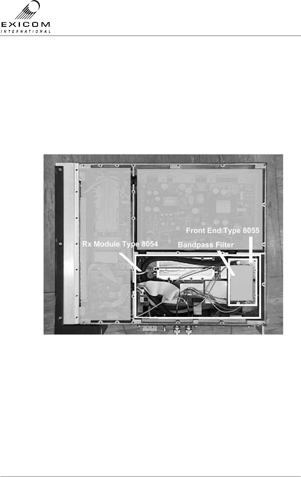
EX7100 Technical Manual - Module Descriptions
©1999 Exicom Technologies (1996) Ltd 7-40 Issue 3 - May 2001
7.8 UHF Receiver Module Type 8054
7.8.1 General
Received RF is passed from the antenna through the Duplexer to the Front End sub-
module Type 8055 where it is filtered and amplified. This RF is applied to the Receiver
module’s RF input, it is then filtered, amplified, mixed and demodulated.
The microcontroller on the Transmitter module provides metering for the receiver,
generates the automatic gain control (AGC) voltages, controls the Receiver module’s
synthesisers and stores receiver configuration information.
Figure 7.23: UHF Receiver Module in Place within Terminal
7.8.2 Testing and Fault Diagnosis
General
Note: Refer to Section 5 “Troubleshooting the EX7100” before reading this section.
The Transmitter module provides control to both the Receiver module and the Receiver
Front-End module (AGC and synthesiser setting) and also collects measurements from
the Receiver modules. An apparent Receiver problem may actually be caused by a fault
with the Transmitter module.

EX7100 Technical Manual - Module Descriptions
©1999 Exicom Technologies (1996) Ltd 7-41 Issue 3 - May 2001
The module contains semi-conductor components that are
sensitive to electrostatic damage.
Electrostatic sensitive devices should only be stored and
transported inside electrically conductive static shielding
bags. Fault finding and module replacement must be
performed at “electrostatically safe work stations” where the
work bench surface, soldering iron and the operator are all
earthed to prevent the build up of harmful electrostatic
charges.
Accessing the UHF Receiver Module
To gain service access to the Receiver module, remove the bottom cover as per Section
6.1.
Diagnosis
With the unit de-powered, check the receiver module visually for signs of damage such
as burnt tracks or components. Check that all connectors are fully mated. If no damage
is apparent, apply power and follow the steps outlined in Figure 7.24 overleaf
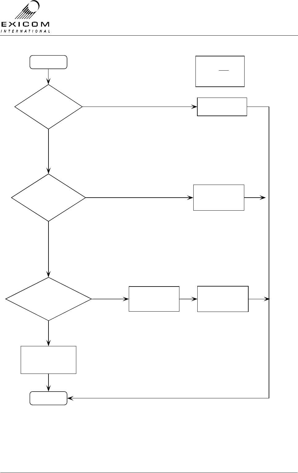
EX7100 Technical Manual - Module Descriptions
©1999 Exicom Technologies (1996) Ltd 7-42 Issue 3 - May 2001
Figure 7.24: UHF Receiver Module Fault Diagnostic Tree
Begin
Rec eive
Frequency
correct?
Rec eiver
Front-end tuned
correctly?
Set correct
Receive Frequency
Yes
No
No
Caution:
Antenna
output mus t be
terminated in 50 Ohms
Yes
Tune Front-end filter
RSSI
Measurements
OK?
Finish
Suspect that Receiver
or Transmitter module
is faulty
Receiver module appears
to be fault-free, suspect
that another Module is
faulty
No
Replace Receiver or
Transmitter Module
Yes

EX7100 Technical Manual - Module Descriptions
©1999 Exicom Technologies (1996) Ltd 7-43 Issue 3 - May 2001
7.8.3 Alignment
Re-tuning Of the Receiver Module
If the frequency of the Receiver module is to be changed by more than ±2.5 MHz from its
tuned frequency, the following checks or adjustments are required:
Checking the VCO Loop Voltage
1. Set the new Receive frequency via the front panel as per Section 3.
2. Remove the bottom cover and refer to Figure 7.25 below to identify the location of
the Loop Volts output feed-through capacitor in the local oscillator module. Check
with a digital multi-meter (DMM) that the VCO Loop Volts measurement is within the
range of 3 to 4 Volts DC.
If necessary, reset this by adjusting VCO trimmer capacitor CV101 as indicated in
Figure 7.25 below. (It will be necessary to remove the screw in the aluminium block
to access the trimmer. Always replace this screw after adjustment).
Figure 7.25: Location of Loop Volts adjustment CV101
Adjustment of the receiver bandpass filter
1. With the bottom cover removed, set terminal to ‘On-demand’ mode to ensure the
transmitter is turned off.
2. Remove the bottom cover as described in Section 6.1; disconnect the coaxes from
SK101 and SK102 on the Receiver Front-End module. Feed the output of SK102 to
the RF input of a scalar network analyser (or spectrum analyser with tracking
generator), with reference amplitude of -10dBm and span of 4MHz/div.
3. Set the RF output of the analyser’s tracking generator level to -50dBm and feed it into
socket SK101 on the Receiver Front-End module.
4. The filter is made up of a dual tuneable helical package (FL101) and triple tuneable
helical packages (FL102 and FL103) all within a tin can mounted on the PCB. Using
a suitable tuning tool, adjust FL102 and FL103 to “walk” the filter response along,
until it is centred on the desired receive frequency. Then tune FL101 for maximum
gain and sharpest response at the desired frequency.

EX7100 Technical Manual - Module Descriptions
©1999 Exicom Technologies (1996) Ltd 7-44 Issue 3 - May 2001
Due to the interaction between the filter components, it is advisable to repeat this
procedure a number of times.
5. Disconnect the analyser. Reconnect the Duplexer to SK101 and the Receiver Module
to SK102.
6. Disconnect the analyser. Reconnect the Duplexer to SK101 and the Receiver Module
to SK102.
Note: The Duplexer module must also be adjusted to suit the new centre frequency
(refer to Section 7.10.3 for tuning details).
Receiver Maintenance Adjustments
The baseband DC offset may drift with age. To check or adjust:
1. Connect an oscilloscope in XY mode to PL301 (pins 1 and 3). Ensure that the
oscilloscope is DC coupled and centred on the display.
2. Disable the transmitter by setting the terminal to On-demand operation in the
Terminal Set-up menu (Refer to Section 3 for details).
3. Put the EX7100 terminal into Align Mode with CW and Tx: Low selected. (Refer to
Section 4.5.1).
4. Apply an un-modulated RF carrier at approximately –80dBm on channel into the
receiver (W101)
5. A circle should appear on the oscilloscope. Adjust the signal generator RF level for a
circle of ~2 volts peak to peak diameter.
Adjust RV301 and RV302 to centre circle about 0 volts (i.e. remove the DC offset).
7.8.4 UHF Receiver Replacement Procedure
Note: It is necessary to remove the Front-End module prior to replacing the Receiver
module, however, the Front-End module can be replaced without removal of the
Receiver module.
Removal of the Type 8055 Front-End Module
1. Isolate the EX7100 Terminal from the incoming DC supply by removing the DC input
wires from the rear panel terminal block.
2. Remove the bottom cover as described in Section 6.1.
3. Note the connector positions and the way that the cables are run (it is important that
all cables are replaced as they were initially run before the module replacement
procedure).
4. Remove coaxial connectors SK101 & SK102 from the Receiver Front-End module
and connector PL104 from the Receiver board.
5. Remove the four screws holding the Receiver Front-End module and lift the Front-
End PCB out of the casting.
6. Position the new Receiver Front-End Module and replace the four mounting screws.

EX7100 Technical Manual - Module Descriptions
©1999 Exicom Technologies (1996) Ltd 7-45 Issue 3 - May 2001
7. Re-connect all cables as removed in 4. above. Ensure that all cables are run as they
were prior to removal.
8. Inspect the EX7100 terminal to ensure that it is free of foreign material. Remove and
clean as required.
9. Connect the antenna to the terminal. Apply power to the EX7100 rear panel and
switch the terminal on.
10. If necessary, retune the Receiver Front-End module (refer to Section 7.8.3).
11. Reset the receive frequency and other variables as necessary (refer to Section 3 as
required)
12. Return to normal operating mode and check that the link is correctly established. If
not refer to Section 7.8.2 above and Section 5 “Troubleshooting” as required.
13. Replace the bottom cover, taking care to tighten every screw. No screws should be
left over at the end of the job.
14. Re-install the EX7100 back into its rack and re-connect all necessary power,
signalling and antenna cabling.

EX7100 Technical Manual - Module Descriptions
©1999 Exicom Technologies (1996) Ltd 7-46 Issue 3 - May 2001
Removal of the Receiver module
1. Remove the Front-End module as previously described.
Remove the following connectors from the Receiver PCB:
PL101, PL102 and PL103.
2. Remove the two stand-offs and two M3 screws and washers that hold the Receiver
module into the casting, then remove the Receiver module, keeping all fastenings in
a safe place.
3. Remove the two stand-offs that retain the Front-End module to the Receiver module
and refit to the new Receiver module.
4. Place four nylon spacers on top of the four bosses and carefully position the new
Receiver PCB into the casting, taking care not to flex the PCB as this can cause
damage to the surface mounted components. Refit the two screws and remaining
stand-offs, tightening carefully.
5. Reconnect connectors PL101, PL102 and PL103 on the Receiver module. Ensure
that all cables are run as they were prior to removal.
6. Replace the Front-End module as previously described. Ensure that all cables are
run as they were prior to removal.
7. Inspect the EX7100 terminal to ensure that it is free of foreign material. Remove and
clean as required.
8. Connect the antenna to the terminal. Apply power to the EX7100 rear panel and
switch the terminal on.
9. If necessary, retune the Receiver Front-End module (refer to Section 7.8.3).
10. Reset the receive frequency and other variables as necessary (refer to Section 3 as
required)
11. Return to normal operating mode and check that the link is correctly established. If
not refer to Section 7.8.2 above and Section 5 “Troubleshooting” as required.
12. Replace the bottom cover, taking care to tighten every screw. No screws should be
left over at the end of the job.
13. Re-install the EX7100 back into its rack and re-connect all necessary power,
signalling and antenna cabling.

EX7100 Technical Manual - Module Descriptions
©1999 Exicom Technologies (1996) Ltd 7-47 Issue 3 - May 2001
7.9 VHF Duplex Filter Module Type 8013
7.9.1 General
The Duplex Filter (or Duplexer) allows the receiver and transmitter modules to be
connected to one antenna at each terminal.
This is achieved with selective filtering. At the receive frequency the antenna port of the
Duplexer is connected as directly as possible to the receiver input. Similarly at the
transmit frequency the antenna port is connected as directly as possible to the transmitter
PA output.
The Duplexer isolates the receiver from the large signals produced by the transmitter. In
addition, it provides significant protection against lightning damage to the radio.
Note: The use of suitable earthing and an external lightning arrester is recommended at
all times, refer to Section 2.6.1 for further details.
Four VHF Duplexer variants are available: one Duplexer covers 138 to 156MHz and
another 152 to 175MHz. For each frequency range there is a version for 4 to 6 MHz
Rx/Tx spacing and another version for 6 to 15 MHz spacing.
VHF Connections
The Duplexer module has three connection ports: Antenna, High and Low.
Antenna Provides RF connection to/from the installed antenna.
High Connection is dependent on the Tx and Rx operating frequency pair. If the
Tx operates on the higher frequency, the High port connects to the PA
output (PL102). If the Rx operates on the higher frequency, the High port
connects to the Receiver Front-End input (SK101).
Low Connection will be the reverse of that detailed above, dependent on which
module is using the lower frequency.
VHF Mounting
The VHF Duplexer module is mounted on the underside of the Top Cover via 4 threaded
studs and associated fasteners (refer to Section 7.9.4 Duplexer Replacement Procedure).

EX7100 Technical Manual - Module Descriptions
©1999 Exicom Technologies (1996) Ltd 7-48 Issue 3 - May 2001
7.9.2 Testing and Fault Diagnosis
General
Note: Refer to Section 5 “Troubleshooting the EX7100” before reading this Section.
The Duplexer is a passive product that once correctly aligned should provide stable
performance without failure.
The major failure modes of Duplexers are:
> Connectors not being fully mated or cable failure.
> Incorrect Duplexer tuning, causing degraded transmitter and/or receiver
performance.
> Mechanical failure of internal components, usually causing complete failure of the
link.
Fault-finding methods are:
1. Check that the RF connectors are fully mated.
2. Substitute the Duplexer for one that is known to be correctly tuned or
3. Check the Duplexer’s performance using a network analyser (refer to Section 7.9.3).
Checking RF Connectors
Remove the top and bottom covers as per Section 6.1.
With the terminal de-powered, check that the three RF connectors on the Duplexer are
fully mated. Similarly, check that the PA, Transmitter and Receiver module coax
connectors are fully home.
If no problems are found with the connections, either check the performance of the
Duplexer with an analyser (refer Section 7.9.3) or replace the Duplexer (refer Section
7.9.4).
7.9.3 Alignment
VHF Module Re-tuning
Duplexer adjustment requires the use of a scalar network analyser with the performance
outlined in Table 7.4 below.
Measurement Preferred Capability Minimum Capability
Transmission: Dynamic Range
& Isolation
95dB 80dB
Return Loss: Capability 30dB 20dB
Table 7.4: Required Measurement Capability
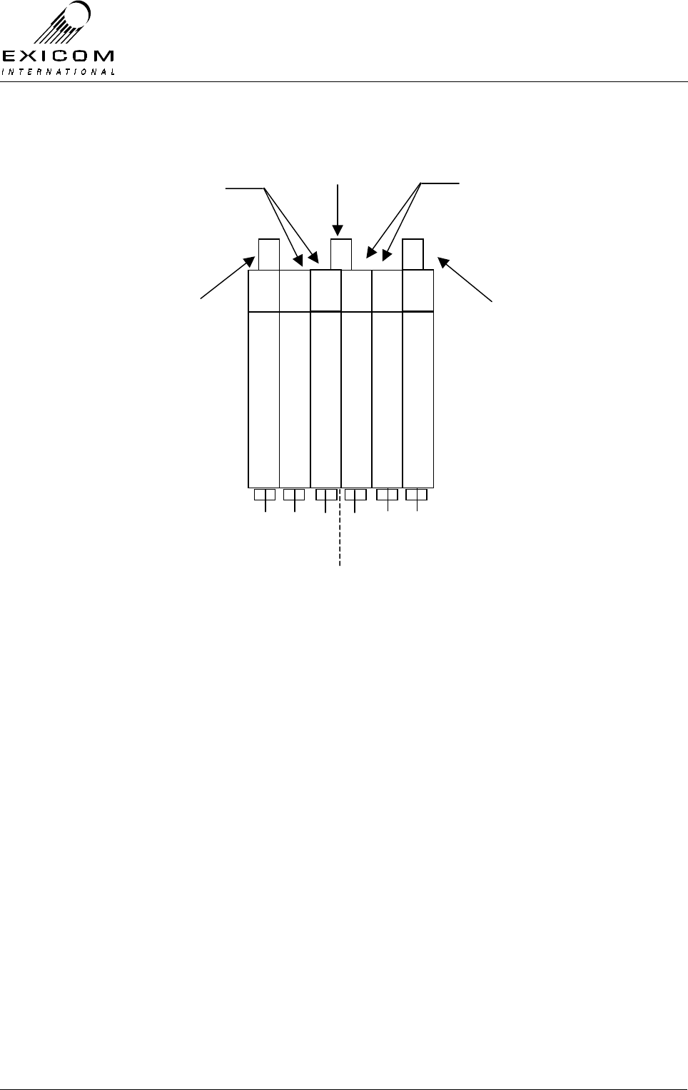
EX7100 Technical Manual - Module Descriptions
©1999 Exicom Technologies (1996) Ltd 7-49 Issue 3 - May 2001
Refer to Figure 7.26 and the steps outlined below:
Figure 7.26: VHF Duplex Filter Adjustment Locations
1. Connect a 50Ω termination to the antenna port.
2. Connect the analyser input to the high frequency port.
3. Feed the tracking generator output into the low frequency port of the Duplexer. Set
the analyser to the maximum output level available.
4. Adjust the three low pass adjustment screws to maximise the notch on the high
operating frequency of the Duplexer.
5. Adjust the three high pass adjustment screws to maximise the notch on the low
operating frequency of the Duplexer.
6. Repeat the two steps above until the notches are centred and maximised on the two
notch frequencies. The notches should provide greater than 85dB isolation (typically
90dB). On many analysers, it is not possible to measure the full isolation, as there is
not sufficient dynamic range available.
7. Check that the insertion loss from the low frequency port to the antenna port is less
than 1.5dB (0.8dB typical).
8. Check that the insertion loss from the high frequency port to the antenna port is less
than 1.5dB (0.8dB typical).
9. Check that the return loss into the high and low frequency ports is better than 16dB.
High Pass Adjustment Screws Low Pass Adjustment Screws
High Freq Port Low Freq Port
High Freq Port
matching capacitors
Low Freq Port
matching inductors
Antenna Port

EX7100 Technical Manual - Module Descriptions
©1999 Exicom Technologies (1996) Ltd 7-50 Issue 3 - May 2001
7.9.4 VHF Duplex Filter Replacement Procedure
Note: Ensure that the replacement module has been correctly tuned to the operating
frequencies required before installation (refer to Section 7.9.3 above)
1. Isolate the EX7100 Terminal from the incoming DC supply by removing the DC input
wires from the rear panel terminal block.
2. Remove the top cover as described in Section 6.1.
3. Note the connector positions and the way that the cables are run (it is important that
all cables are replaced as they were initially run before the module replacement
procedure). Disconnect the three coax cables from the Duplexer.
4. Remove the fasteners holding the Duplexer to the cover and lift it clear.
5. Fit the new Duplexer over the threaded studs and replace the fasteners. Tighten the
fasteners.
6. Reconnect the three coaxes to the positions recorded previously.
7. Inspect the EX7100 terminal to ensure that it is free of foreign material. Remove and
clean as required.
8. Connect the antenna to the terminal. Apply power to the EX7100 rear panel and
switch the terminal on.
9. Check that the received signal strength (RSSI) and forward power are at the levels
expected and that the VSWR alarm is not being generated.

EX7100 Technical Manual - Module Descriptions
©1999 Exicom Technologies (1996) Ltd 7-51 Issue 3 - May 2001
7.10 UHF Duplex Filter Module Type 8045
7.10.1 General
The Duplexer allows the receiver and transmitter modules to be connected to one
antenna at each terminal.
This is achieved with selective filtering. At the receive frequency the antenna port of the
Duplexer is connected as directly as possible to the receiver input. Similarly at the
transmit frequency the antenna port is connected as directly as possible to the transmitter
PA output.
The Duplexer is made up of a four cavity notch filter, a Band Pass Band Reject (BPBR)
filter and a Band Reject Band Pass filter (BRBP).
The BPBR is a low pass filter and is connected to the Receiver or Transmitter operating
on the low frequency.
The BRBP is a high pass filter and is connected to the Receiver or Transmitter operating
on the high frequency.
The Duplexer isolates the receiver from the large signals produced by the transmitter. In
addition, it provides significant protection against lightning damage to the radio.
Note: The use of suitable earthing and an external lightning arrester is recommended at
all times, refer to Section 2.6.1 for further details.
The Duplexer covers 406-470MHz with a 9-13MHz Rx/Tx spacing.
UHF Connections
The Duplex filter module has three connection ports: Antenna, High and Low.
Antenna Provides RF connection to/from the installed antenna.
High Connection is dependent on the Tx and Rx operating frequency pair.
If the Tx operates on the higher frequency, the High port connects, via the
BRBP filter, to the PA output (PL102).
If the Rx operates on the higher frequency, the High port connects, via the
BRBP filter, to the Receiver Front-End input (SK101).
Low Connection will be the reverse of that detailed above, dependent on which
module is using the lower frequency.
UHF Mounting
The Duplexer module is externally mounted on the EX7100 terminal Top Cover via 14
threaded studs and associated fasteners (refer to 7.10.5 Duplexer Replacement
Procedure).

EX7100 Technical Manual - Module Descriptions
©1999 Exicom Technologies (1996) Ltd 7-52 Issue 3 - May 2001
7.10.2 Testing and Fault Diagnosis
General
Note: Refer to Section 5 “Troubleshooting the EX7100” before reading this Section.
The Duplexer is a passive product that once correctly aligned should provide stable
performance without failure.
The major failure modes of Duplexers are:
> Connectors not being fully mated or cable failure.
> Incorrect Duplexer tuning, causing degraded transmitter and/or receiver
performance.
> Mechanical failure of internal components, usually causing complete failure of the
link.
Fault-finding methods are:
1. Check that the RF connectors are fully mated.
2. Substitute the Duplexer for one that is known to be correctly tuned or
3. Check the Duplexers performance using a network analyser (refer to Section 7.10.3).
Checking RF Connectors
With the terminal de-powered, check that the eight RF connectors on the Duplexer are
fully mated. Similarly, check that the two RF connectors on the terminal rear panel are
fully home.
If no problems are found with the connections, either check the performance of the
Duplexer with an analyser (refer Section 7.10.3) or replace the Duplexer (refer Section
7.10.5).
7.10.3 Alignment
UHF Module Re-tuning
Duplexer adjustment requires the use of a scalar network analyser with the performance
outlined in Table 7.4 below.
Measurement Preferred Capability Minimum Capability
Transmission: Dynamic Range
& Isolation
95dB 80dB
Return Loss: Capability 30dB 20dB
Table 7.4: Required Measurement Capability

EX7100 Technical Manual - Module Descriptions
©1999 Exicom Technologies (1996) Ltd 7-53 Issue 3 - May 2001
Refer to Figure 7.27 and the steps outlined below:
Figure 7.27: UHF Duplex Filter Adjustment Locations
Note: From this point on the whole assembly will be referred to as the “Duplexer”, the
Band Reject Band Pass filter will be referred to as “BRBP”, the Band Pass Band Reject
filter as “BPBR” and the larger notch filter as “Duplex filter”.
The Duplexer is tuned in two steps. Initially the three parts (BRBP, BPBR and Duplex
filter) are tuned separately. The three parts are then connected together and the final
tuning is carried out to take into account the interaction between the three parts.
Bracketed ( ) numbers refer to the port numbers in figure 7.27 above.
Before undertaking the following procedures, ensure that the EX7100 terminal has been
powered down.
BRBP
Band Reject
Band Pass
Filter
(HPF)
BPBR
Band Pass
Band Reject
Filter
(LPF)
4 Cavity Duplex filter
High Low
low pass
adjustment
High pass
adjustment
Tx or Rx Tx or RxAntenna
1234567
A B C D E F G H I J

EX7100 Technical Manual - Module Descriptions
©1999 Exicom Technologies (1996) Ltd 7-54 Issue 3 - May 2001
Note1: Note that on many analysers, it is not possible to measure the full isolation, as
there is not sufficient dynamic range available. Therefore, it is suggested that the trace, at
the point where it becomes noise, be centred on the centre vertical graticule of the
instrument. Check the notch depth (Isolation Loss) at this point.
BRBP Filter adjustment (HPF)
1. Disconnect both coax leads from the BRBP section of the Duplexer.
2. Connect the analyser input to port (1).
3. Feed the tracking generator output into port (2). Set the analyser to the low frequency
of the terminal at the maximum output level available.
4. Adjust the three adjustment screws on the BRBP filter for the deepest notch on the
low operating frequency of the terminal (See Note1 above). Check that the notch
depth (Isolation Loss) is ≥ 80dB.
5. Check that the Insertion Loss is ≤ 1.0dB.
6. Reconnect all leads to the BRBP filter.
BPBR Filter adjustment (LPF)
1. Disconnect both coax leads from the BPBR section of the Duplexer.
2. Connect the analyser input to port (7).
3. Feed the tracking generator output into port (6). Set the analyser to the high
frequency of the terminal at the maximum output level available.
4. Adjust the three adjustment screws on the BPBR filter for the deepest notch on the
high operating frequency of the terminal (See Note1 above). Check that the notch
depth (Isolation Loss) is ≥ 80dB.
5. Check that the Insertion Loss is ≤ 1.0dB.
6. Reconnect all leads to the BPBR filter.
Duplex Filter adjustment
1. Disconnect the “High” and “Low” coax leads from the Duplex filter section of the
Duplexer. Connect a 50Ω load to the Antenna port (4).
2. Connect the analyser input to the high frequency port (3).
3. Feed the tracking generator output into the low frequency port (5). Set the analyser to
the high frequency of the terminal at the maximum output level available.
4. Adjust the two low pass adjustment screws on the Duplex filter for the deepest notch
on the high operating frequency of the terminal (See Note1 above). Check that the
notch depth (Isolation Loss) is ≥ 80dB.

EX7100 Technical Manual - Module Descriptions
©1999 Exicom Technologies (1996) Ltd 7-55 Issue 3 - May 2001
5. Adjust the two high adjustment screws on the Duplex filter for the deepest notch on
the low operating frequency of the terminal (See Note1 above). Check that the notch
depth (Isolation Loss) is ≥ 80dB.
6. Check that the Insertion Loss is ≤ 1.0dB.
7. Reconnect all leads to the Duplex filter.
7.10.4 Duplexer Tuning / Performance Checks
With the three sections of the Duplexer connected together as shown in figure 7.27,
check the following performance parameters:
Notch Depth (Isolation Loss)
Low Pass Filter:
1. Connect a 50Ω termination to the antenna port (4).
2. Connect the analyser input to the high frequency port (1).
3. Feed the tracking generator output into the low frequency port (7) of the Duplexer.
Set the analyser to the maximum output level available.
4. With the tracking generator output set to the high frequency, check that the filter
notch is ≥80dB. If a non-compliance is observed, the Duplexer tuning screws F, G, H,
I may be slightly adjusted. Upon adjustment, all performance parameters of the
Duplexer must be re-checked.
High Pass Filter:
1. Connect a 50Ω termination to the antenna port (4).
2. Connect the analyser input to the low frequency port (7).
3. Feed the tracking generator output into the high frequency port (1) of the Duplexer.
Set the analyser to the maximum output level available.
4. With the tracking generator output set to the low frequency, check that the filter notch
is ≥80dB. If a non-compliance is observed, the Duplexer tuning screws B, C, D, E
may be slightly adjusted. Upon adjustment, all performance parameters of the
Duplexer must be re-checked.
Insertion Loss
Low Pass Filter:
1. Connect a 50Ω termination to the high frequency port (1).
2. Connect the analyser input to the Antenna port (4).
3. Feed the tracking generator output into the low frequency port (7) of the Duplexer.
Set the analyser to the maximum output level available.

EX7100 Technical Manual - Module Descriptions
©1999 Exicom Technologies (1996) Ltd 7-56 Issue 3 - May 2001
4. With the tracking generator output set to the low frequency, check that the filter
insertion loss is < 2.0dB (1.5-2.0dB typical). If a non-compliance is observed, the
Duplexer tuning screws F, G, H, I may be slightly adjusted. Upon adjustment, all
performance parameters of the Duplexer must be re-checked.
High Pass Filter:
1. Connect a 50Ω termination to the low frequency port (7).
2. Connect the analyser input to the Antenna port (4).
3. Feed the tracking generator output into the high frequency port (1) of the Duplexer.
Set the analyser to the maximum output level available.
4. With the tracking generator output set to the high frequency, check that the filter
insertion loss is < 2.0dB (1.5-2.0dB typical). If a non-compliance is observed, the
Duplexer tuning screws B, C, D, E may be slightly adjusted. Upon adjustment, all
performance parameters of the Duplexer must be re-checked.
Note: Reconnect all cables as per Figure 7.27
7.10.5 UHF Duplex Filter Replacement Procedure
Note: Ensure that the replacement module has been correctly tuned to the operating
frequencies required before installation (refer to Section 7.10.3 above)
1. Isolate the EX7100 Terminal from the incoming DC supply by removing the DC input
wires from the rear panel terminal block.
2. Note the connector positions and the way that the cables are run (it is important that
all cables are replaced as they were initially run before the module replacement
procedure). Disconnect the coax cables from the Duplexer.
3. Remove the fasteners holding the Duplexer to the cover and lift it clear.
4. Fasten the new Duplexer to the cover.
5. Reconnect the coaxes to the positions recorded previously.
6. Inspect the EX7100 terminal to ensure that it is free of foreign material. Remove and
clean as required.
7. Connect the antenna to the terminal. Apply power to the EX7100 rear panel and
switch the terminal on.
4. Check that the received signal strength (RSSI) and forward power are at the levels
expected and that the VSWR alarm is not being generated.
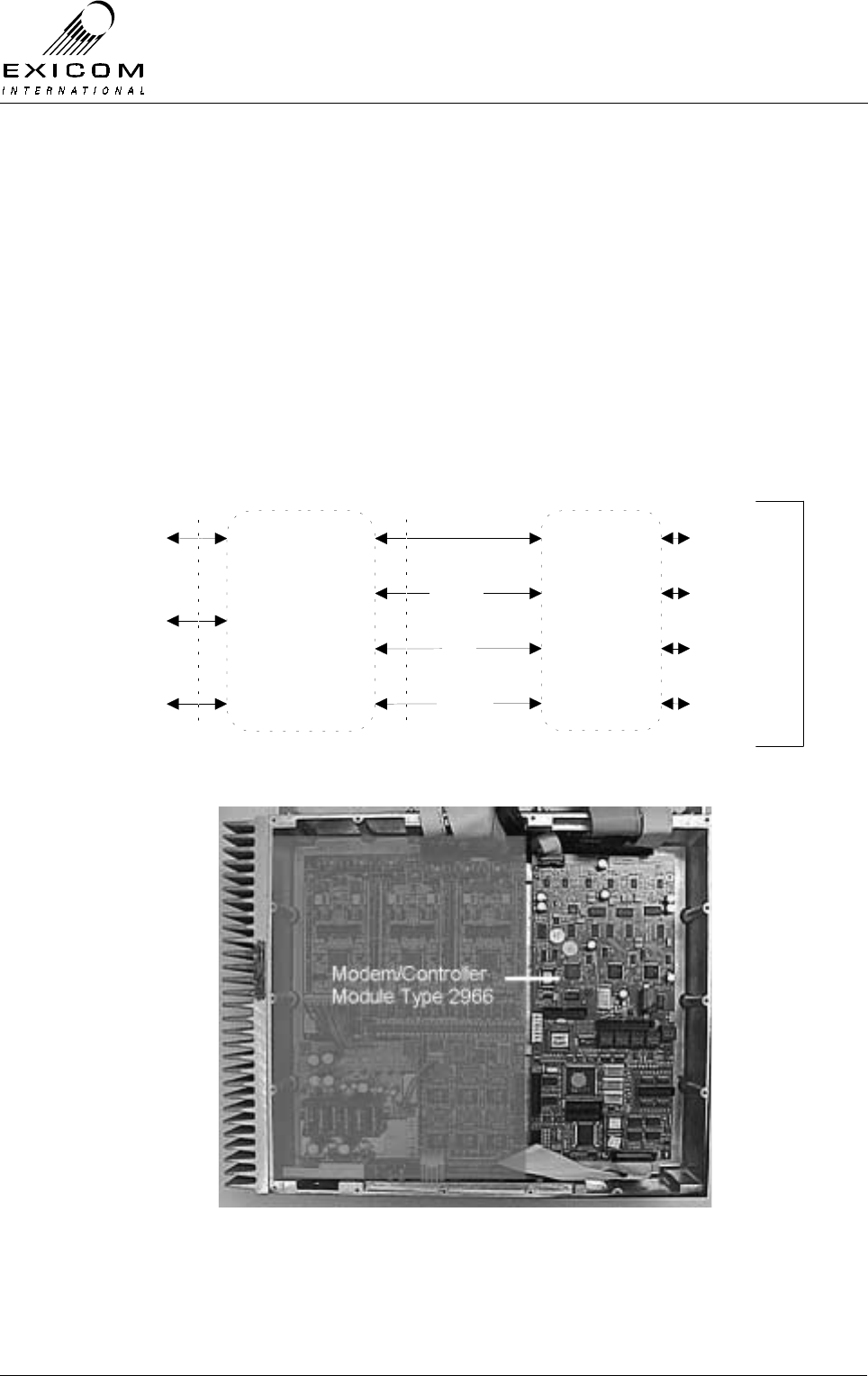
EX7100 Technical Manual - Module Descriptions
©1999 Exicom Technologies (1996) Ltd 7-57 Issue 3 - May 2001
7.11 Modem/Controller Module Type 2966
7.11.1 General
The Modem/Controller module provides the bulk of the EX7100 terminal’s control and
data conversion functionality. Incoming line data to the terminal is converted to a format
suitable for transmission over the link and output to the transmitter module. Similarly, data
from the receiver is converted from the transmission format to the line format appearing
at the rear panel.
This module also contains the master controller for the EX7100. This controls the Front
Panel module and manages the microcontrollers that are present on many of the other
modules. A Rear Panel Data Connector PCB connects the Modem/Controller PCB to the
external world.
Modem/Controller
Module
Rear Panel
Data
Connector
PCB
64k Data &
Clocks
I/O Port
Ribbon
Connector From
Modem Controller
Control
LMS
64kbps Data
Control
LMS
I/O
Front Panel
Module
RX&TX
64k Data
Module
Comms
Bus
Rear Panel
Connectors
Ribbon
Connector From
Modem Controller
Figure 7.28: Modem/Controller Block Diagram
Figure 7.29: Modem/Controller in Place within Terminal

EX7100 Technical Manual - Module Descriptions
©1999 Exicom Technologies (1996) Ltd 7-58 Issue 3 - May 2001
7.11.2 Testing and Fault Diagnosis
The module contains semi-conductor components that are
sensitive to electrostatic damage.
Electrostatic sensitive devices should only be stored and
transported inside electrically conductive static shielding
bags. Fault finding and module replacement must be
performed at “electrostatically safe work stations” where the
work bench surface; soldering iron and the operator are all
earthed to prevent the build up of harmful electrostatic
charges.
The Modem/Controller module contains a lithium battery.
There is a danger of explosion if the battery is incorrectly
replaced. Replace only with the same or equivalent type
recommended by the manufacturer.
Dispose of used batteries according to the manufacturers
instructions.
General
The Modem/Controller module is very complex and interacts with all of the other modules
and control systems within the EX7100 terminal.
For this reason, a faulty Modem/Controller module may cause symptoms that appear
elsewhere, and faults elsewhere may cause symptoms to appear at the
Modem/Controller module.
Accessing the Modem/Controller
To gain service access to the Modem/Controller module, remove the top cover as per
Section 6.1.
Diagnosis
Under normal operating conditions and with a link established, D8, D100, D101 and D102
should all be on. If this is not the case, follow the instructions below:
With the unit de-powered, check the Modem/Controller module visually for signs of
damage such as burnt tracks or components. Check that all connectors are fully mated
and that all socketed ICs are fully inserted.
If no damage is apparent, attach the antenna and power leads. Follow the steps in Figure
7.30 overleaf.
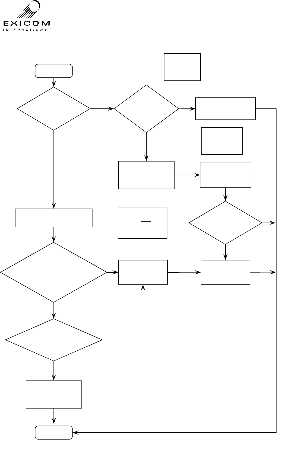
EX7100 Technical Manual - Module Descriptions
©1999 Exicom Technologies (1996) Ltd 7-59 Issue 3 - May 2001
Figure 7.30: Modem/Controller Fault Diagnostic Tree
Begin
EX7100 LCD
operational?
Pow er Supply
Voltages OK?
Sw itch on EX7100 Terminal with
Top Cover Removed
D501 on continuously?
D104 should be off.
D103 (Red LED) flashes
once then stays off?
Suspect that
Modem/Controller
module is faulty
Suspect that the Pow er
Supply module is faulty
Yes
No
No
No
Ref er to Pow er
Supply Module
Section 7.2
Suspect that the Front
Panel module or
Modem/Contr oller module
is faulty
Yes Refer to Front
Panel Module
Section 7.12
Replace Front Panel
module
EX7100 LCD
operational?
Yes
Replace
Modem/Controller
module
No
Caution:
Antenna
output mus t be
terminated in 50 Ohms
Yes
D100, D101 and D102
turn on sequentially?
Modem/Controller module
appears to be fault-free,
suspect that another
Module is faulty
Yes
Finish
No

EX7100 Technical Manual - Module Descriptions
©1999 Exicom Technologies (1996) Ltd 7-60 Issue 3 - May 2001
7.11.3 Alignment
The Modem/Controller module requires no alignment and has no user adjustments.
7.11.4 Modem/Controller Module Replacement Procedure
1. Isolate the EX7100 Terminal from the incoming DC supply by removing the DC input
wires from the rear panel terminal block.
2. Remove the top cover as described in Section 6.1.
3. Note the connector positions and the way that the cables are run (it is important that
all cables are replaced as they were initially run before the module replacement
procedure).
4. Remove connections PL1, PL2, PL3, PL4, PL8, PL9 and PL502 from the
Modem/Controller module
5. Remove the six M3 screws and washers that retain the module. Keep the screws in a
safe place.
6. Carefully position the new Modem/Controller PCB into the casting taking care not to
flex the PCB as this can cause damage to the surface mounted components.
Replace the six M3 PCB mounting screws. Carefully tighten the screws.
7. Re-connect all cables as removed in 4. above. Ensure that all cables are run as they
were prior to removal.
8. Inspect the EX7100 terminal to ensure that it is free of foreign material. Remove and
clean as required.
9. Connect the antenna to the terminal. Apply power to the EX7100 rear panel and
switch the terminal on. Check that at turn-on the two PCB mounted red LED's stay on
for approximately one second and then extinguish. D501 should be on continuously
and D104 should be off. As the link starts up, green LED's D100, D101 and D102
should come on sequentially (note that a full link must be established to meet this
requirement). If red LED D103 continue to flash, the Modem/Controller module is
probably faulty.
10. Replace the top cover, taking care to tighten every screw. No screws should be left
over at the end of the job.
11. Re-install the EX7100 back into its rack and re-connect all necessary power,
signalling and antenna cabling.

EX7100 Technical Manual - Module Descriptions
©1999 Exicom Technologies (1996) Ltd 7-61 Issue 3 - May 2001
7.12 Front Panel Module Type 2994
7.12.1 General
The Front Panel module is used for terminal configuration and to check status of various
parameters (refer to Sections 3 and 4 for complete details).
The Front panel operates under the command of the Controller on the Modem Controller
module Type 2966.
Figure 7.31: Front Panel Block Diagram
Data to LCD Liquid Crystal
Display (LCD)
LED Drive Light Emitting
Diodes (LEDs)
& Backlighting
Voltage to
Front Panel
Test points
Front Panel
Test Points
Data From
Keypad Keypad
Ribbon
Connector From
Modem Controller
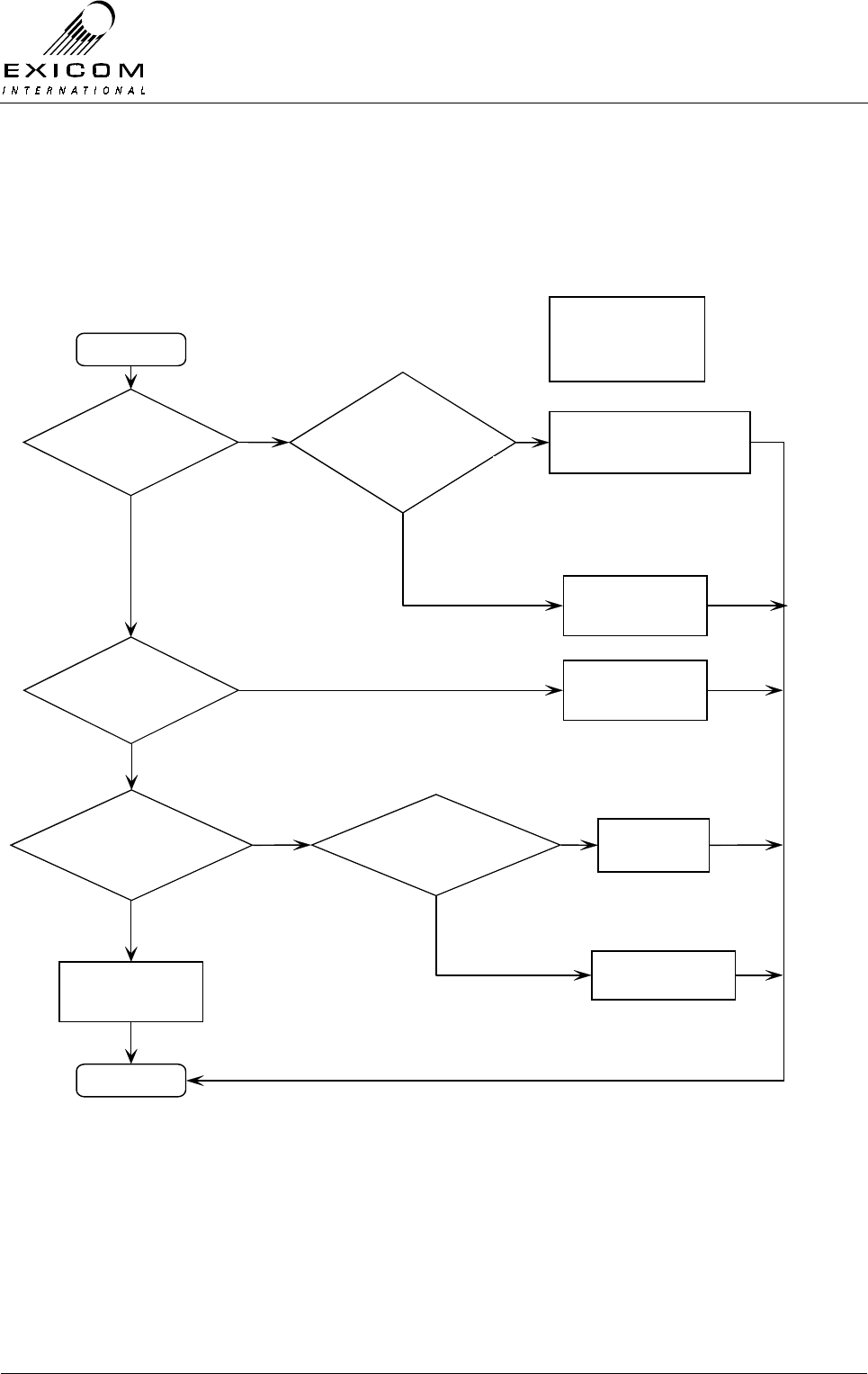
EX7100 Technical Manual - Module Descriptions
©1999 Exicom Technologies (1996) Ltd 7-62 Issue 3 - May 2001
7.12.2 Testing and Fault Diagnosis
If it is suspected that the Display Module is not operating correctly, follow the steps
outlined in Figure 7.32.
Figure 7.32: Front Panel Fault Diagnostic Tree
Begin
Front Panel
Pow er LED on?
Ribbon Cable
Plugged into
Modem/Controller
Card?
Back Lightning
Operates w hen
Button is pushed?
Suspect that Pow er Supply
or Modem/Controller module
is faulty
Yes
No
No
Yes
Refer to Pow er Supply
Module Section 7.2 or
Modem/Controller
Module Section 7.11
Plug Ribbon Cable in
No
Plug Ribbon in
No
Yes
Front Panel module
appears to be
fault-free
Finish
Yes
LCD Operating? Replace Front Panel
Module
No
Yes
Keypad Flexible
Ribbon Plugged in?
Replace Front Panel
Module

EX7100 Technical Manual - Module Descriptions
©1999 Exicom Technologies (1996) Ltd 7-63 Issue 3 - May 2001
7.12.3 Alignment
The Front Panel module requires no alignment and has no user adjustments.
7.12.4 Module Replacement Procedure
Isolate the EX7100 Terminal from the incoming DC supply by removing the DC input
wires from the rear panel terminal block.
1. Remove the six screws that hold the Front Panel to the casting then remove the top
cover as per Section 6.1. Keep all screws in a safe place.
2. Disconnect the Front Panel’s ribbon connector from PL8 on the Modem/Controller
module.
3. Remove the four countersunk M4 screws that hold the Front Panel module into the
casting. Install the new Front Panel module into the casting. Carefully tighten the
screws
4. Re-connect the Front Panel’s ribbon connector to PL8 on the Modem/Controller
module.
5. Refit the front 19” rack-mounting panel using the six screws removed in 1. above.
6. Inspect the EX7100 terminal to ensure that it is free of any foreign debris. Remove
and clean as required.
7. Replace the top cover, taking care to tighten every screw. No screws should be left
over at the end of the job.
8. Connect the antenna to the terminal. Apply power to the EX7100 rear panel and
switch the terminal on. Check that the new Front Panel operates correctly.
9. Re-install the EX7100 back into its rack and re-connect all necessary power,
signalling and antenna cabling.
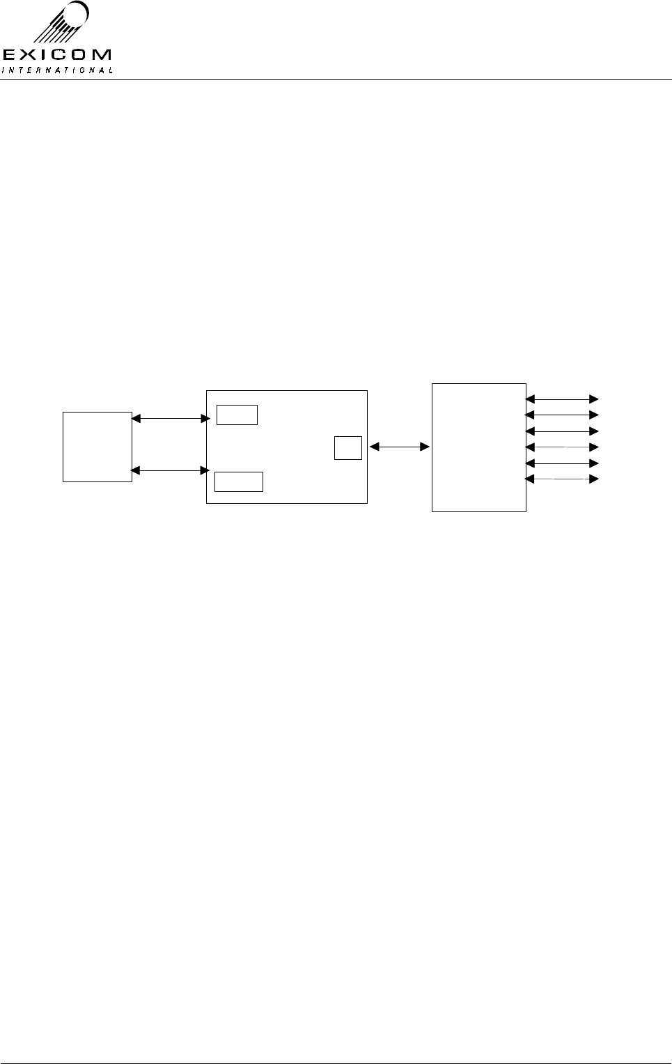
EX7100 Technical Manual - Module Descriptions
©1999 Exicom Technologies (1996) Ltd 7-64 Issue 3 - May 2001
7.13 Line Interfaces Type 2971 and Type 2967
7.13.1 General
Inclusion of a six-channel Line Interface in each EX7100 terminal allows six analogue
exchange or subscriber telephone lines (depending on which module is fitted) to be
operated over the EX7100 link. Voice, fax and data traffic can be accommodated.
Each Line Interface module carries all the necessary line interface, speech compression
and control components.
A 50-way Champ connector is provided on the rear panel for line connections as shown
in Figure 7.33 below.
6 Ch Line I/f Module
(Exch or Subs)
Rear Panel
Champ
Connector
PCB
Analogue
Lines
1
2
3
4
5
6
Modem
Controller
Module
64kb/s
Control
PL902
PL902
PL1
6
Analogue
Lines
Figure 7.33: Six Channel Line Interface Connection Block Diagram
Isolated Power Supply Module Type 2990
Isolated Power Supply Module Type 2990 is attached as a daughter-board; it provides the
necessary power supply rails for each Line Interface.
This sub-module should be considered part of the Line Interface module. Refer to Section
7.14 for details of this module.
Four wire + E & M Interface Type 8022
The Exchange Terminal may be fitted with an optional Four Wire + E & M Interface. This
PCB is positioned above the Two-wire Exchange Interface Card.
Jumpers JP103, JP203, JP303, JP403, JP503 and JP603 allow for selection of positive
or negative M-wire for each of the six channels.
When used in point-to-point configuration (refer to Section 1.2.2), it may be necessary to
increase the audio line levels above the maximum of +3 dBm. In order to achieve this,
jumpers JP101, JP102, JP201, JP202 etc may be set to increase the line level range by 4
dBm i.e. the lower limit changes from -15 dBm to -11 dBm and the upper limit changes
from +3 dBm to +7 dBm.
It should be noted that the line level menu does not change to indicate the increased
range. Care should be taken to add the 4 dB to the value indicated in the menu.
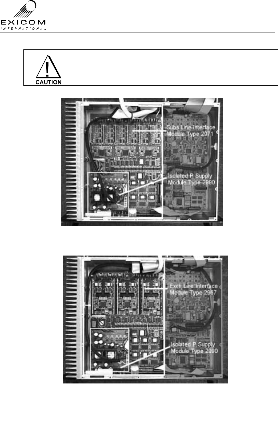
EX7100 Technical Manual - Module Descriptions
©1999 Exicom Technologies (1996) Ltd 7-65 Issue 3 - May 2001
The Isolated Power Supply Module Type 2990 contains a +100V
power rail that is potentially dangerous or lethal. To ensure personal
safety, please observe caution when operating the EX7100 terminal
with the covers removed.
Figure 7.34: Subscriber Line Interface in Place within Terminal
Figure 7.35: Exchange Line Interface in Place within Terminal
EX7100 Technical Manual - Module Descriptions
©1999 Exicom Technologies (1996) Ltd 7-66 Issue 3 - May 2001
7.13.2 Testing and Fault Diagnosis
General
Note: Refer to Section 5 “Troubleshooting the EX7100” before reading this Section.
The module contains semi-conductor components that are
sensitive to electrostatic damage.
Electrostatic sensitive devices should only be stored and
transported inside electrically conductive static shielding
bags. Fault finding and module replacement must be
performed at “electrostatically safe work stations” where the
work bench surface, soldering iron and the operator are all
earthed to prevent the build up of harmful electrostatic
charges.
The Isolated Power Supply Module Type 2990 contains a
+100V power rail that is potentially dangerous or lethal. To
ensure personal safety, please observe caution when
operating the EX7100 terminal with the covers removed
Accessing the Line Interface Module
To gain service access to the Line Interface module:
1. Isolate the EX7100 Terminal from the incoming DC supply by removing the DC input
wires from the rear panel terminal block.
2. Remove the top cover as per Section 6.1. Keep all screws in a safe place.
Diagnosis
Check the module visually for signs of damage such as burnt tracks or components.
Check that socketed ICs are fully home. Check that all connectors are fully mated.
If no problems are apparent, apply power and follow the steps outlined in figure 7.36.
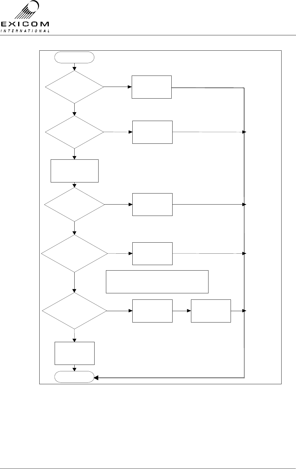
EX7100 Technical Manual - Module Descriptions
©1999 Exicom Technologies (1996) Ltd 7-67 Issue 3 - May 2001
Begin
Modem
Controller D8 on
and D9
off?
Suspect Radio
or Modem
Problem
No
Yes
Suspect Radio
or Modem
Problem
No
Ensure That Full
Duplex Link is
Operating
Loopback
Lines. Loopback
Works On All 6
Lines?
Line Card
Probably
Faulty
Replace Line
Card
No
Line Card Is
probably OK
Finish
Yes
Line Card
Configuration
Correct?
Configure Line
Card
Yes
No
Yes
Line
Interface PSU
Voltages
OK?
Yes
Replace Line
Interface PSU
Module
No
See
Note 1
Note 1: At first turn on, all LEDs adjacent
to the DSPs should be ON. After going off-
hook and DTMF dialling, the LED for the
particular channel will go OFF.
Figure 7.36: Six Channel Line Interface Fault Diagnostic Tree
7.13.3 Alignment/Re-tuning
Each Line Interface module requires no physical alignment or physical user adjustment.

EX7100 Technical Manual - Module Descriptions
©1999 Exicom Technologies (1996) Ltd 7-68 Issue 3 - May 2001
7.13.4 Line Interface Replacement Procedure
This procedure covers the replacement of either Line Interface module.
Refer to Section 6.1 for the initial procedure then:
1. Remove the six screws that hold the Front Panel to the casting.
2. Remove the screw that retains the Isolated Power Supply module’s heat sink block.
3. Note the connector positions and the way that the cables are run (it is important that
all cables are replaced as they were initially run before the module replacement
procedure).
4. Remove PL1, PL2 and PL3 from the Isolated Power Supply module.
5. Remove the four screws that hold the Isolated Power Supply PCB. Lift the Isolated
Power Supply PCB clear of the casting. Keep all screws in a safe place.
6. Remove connections PL1 and PL902 from the Line Interface module. Remove the
grounding wire at the terminal casting lug.
7. Remove the four Isolated Power Supply threaded stand-offs and the five stand-offs
and two screws that retain the Line Interface PCB. Keep the fixings in a safe place.
8. Holding only the edges of the PCB, carefully lift the Line Interface module clear of the
terminal.
9. Carefully position the new Line Interface PCB into the casting, taking care not to flex
the PCB as this can cause damage to the surface mounted components. Replace the
four Isolated Power Supply threaded stand-offs and the five stand-offs and two
screws that hold the PCB into the casting.
10. Refit the Isolated Line Interface PSU module and replace the four screws that hold
the Isolated Power Supply PCB. (Note: The screw with the nylon washer must be
fitted next to PL2 pin 1 on the Isolated Power Supply PCB). Tighten the four
mounting screws.
11. Refit the screw that holds the PSU heat sink block against the main casting.
12. Refit the Front Panel by reversing step 1. above
13. Re-connect all cables as removed in 4. and 6. above. Ensure that all cables are run
as they were prior to removal.
14. Inspect the EX7100 terminal to ensure that it is free of foreign material. Remove and
clean as required.
15. Replace the top cover, taking care to tighten every screw. No screws should be left
over at the end of the job.
16. Re-install the EX7100 back into its rack and re-connect all necessary power,
signalling and antenna cabling.

EX7100 Technical Manual - Module Descriptions
©1999 Exicom Technologies (1996) Ltd 7-69 Issue 3 - May 2001
7.14 Isolated Power Supply Type 2990
7.14.1 General
Isolated power supply module Type 2990 provides DC power to the six-channel
Exchange Interface circuit board Type 2967 and six-channel Subscriber Interface circuit
board Type 2971 as required.
The output rails of the power supply are isolated from the input rail; the isolated supply
can withstand 3.5kV potential difference between input and output.
7.14.2 Description
The module consists of two current-mode flyback converters, switching at approximately
120kHz.
One converter provides the various +5V and –5V rails (analogue and digital supplies) The
other converter provides the -48V rail to power the telephone line and +100V for the ring
voltage generator on the Subscriber Interface circuit.
Both supplies are regulated via optocouplers. None of the output rails are individually
current-limited, but each converter incorporates current limiting in the control IC. This
limits the maximum power that can be delivered to the outputs. All rails except the +100V
rail incorporate LC noise filtering.
A 10-way output connector provides access to the various output rails.
The module runs off the +24V rail provided by the main Power Supply Type 2964 (refer to
Section 7.2). The input connector carries both +24V and +5V.
Note: The +5V input is not used on the module board, but is passed directly onto a
secondary power connector for the non-isolated side of the Interface board.
7.14.3 Testing and Fault Diagnosis
The output rails of the isolated power supply can not be monitored via the front panel. If a
fault is suspected in the isolated power supply, it requires manual testing.
The Isolated Power Supply Module Type 2990 contains a +100V
power rail that is potentially dangerous or lethal. To ensure personal
safety, please observe caution when operating the EX7100 terminal
with the covers removed.
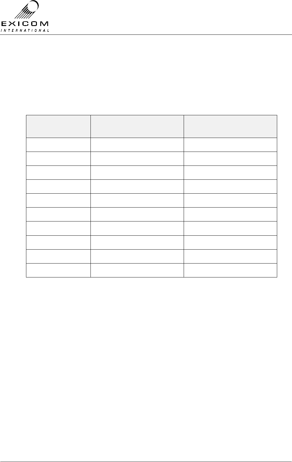
EX7100 Technical Manual - Module Descriptions
©1999 Exicom Technologies (1996) Ltd 7-70 Issue 3 - May 2001
Accessing the Isolated Power Supply Module
Remove the top cover as per Section 6.1.
Diagnosis
1. Connect the negative probe of the digital multi-meter (DMM) to pin 1 of connector
PL2. Using the positive probe of the DMM, touch all the other pins of PL2 in turn and
check the measured voltage against Table 7.5 below:
Pin on
PL2 Expected Voltage Accepted
Tolerance
1 0V ±0.1V
2 +5V ±0.25V
3 -48V ±4.0V
4 +5V ±0.25V
5 0V ±0.1V
6 -5V ±0.5V
7 -5V ±0.5V
8 0V ±0.1V
9 +5V ±0.25V
10 +100V ±10.0V
Table 7.5: Typical Power Supply Measurement Ranges

EX7100 Technical Manual - Module Descriptions
©1999 Exicom Technologies (1996) Ltd 7-71 Issue 3 - May 2001
2. Connect the negative probe of the DMM to pin 2 of connector PL3. Using the positive
probe of the DMM, touch pin 1 of PL3 and check the measured voltage against Table
7.6 below
Pin on
PL3 Expected Voltage Accepted
Tolerance
1 +5V ±0.25V
2 0V ±0.1V
Table 7.6: Typical Power Supply Measurement Ranges

EX7100 Technical Manual - Module Descriptions
©1999 Exicom Technologies (1996) Ltd 7-72 Issue 3 - May 2001
This page intentionally left blank
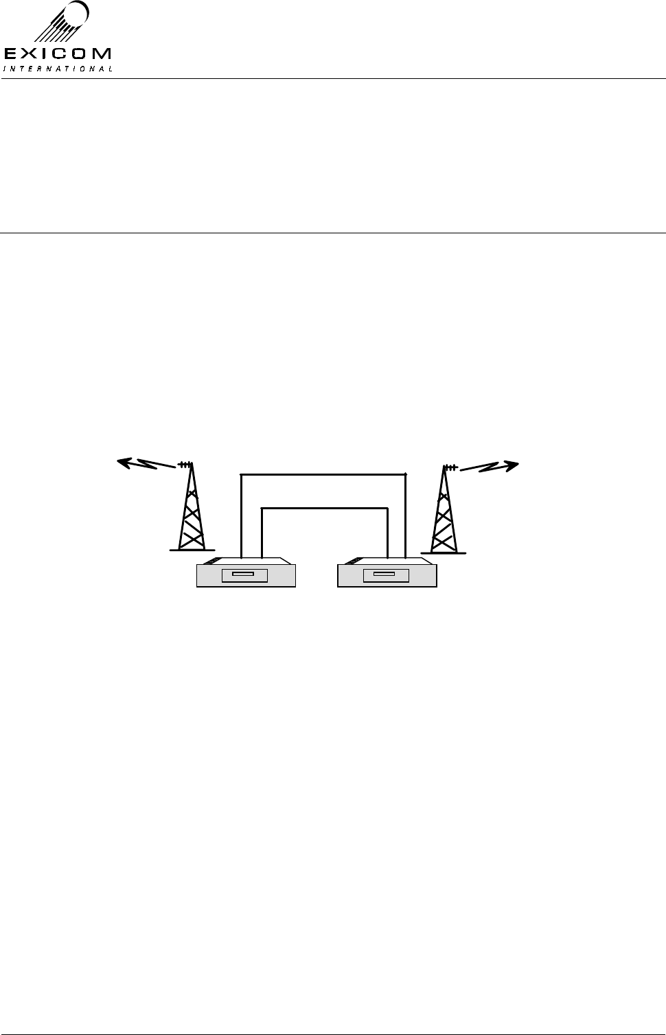
EX7100 Technical Manual – Repeater Configuration
©1999 Exicom Technologies (1996) Ltd 8-1 Issue 1 – February 2001
8
EX7100 Repeater Configuration
8.1 General
The EX7100 can be configured as a full duplex repeater to enable the link to operate over
a much greater distance and over difficult terrain. In repeater configuration, the EX7100
retains the extensive remote monitoring and diagnostics via the system’s internal
engineering channel.
An EX7100 repeater is made up of two 64kbps Data terminals linked back-to-back at the
G.703 level. Any EX7100 terminal may be configured for use as a repeater from its front
panel, enabling a user to redeploy existing link terminals as required.
Figure 8.1: EX7100 Repeater
8.2 Installation
Installation of an EX7100 repeater will follow similar instructions to installing any other
EX7100 terminal. Terminals need to be mounted in close proximity to one another enable
necessary interconnecting cables to be as short as possible.
As the typical location of a repeater site tends to be lightning prone, extra care should be
taken to ensure that all terminal grounding and lightning protection systems are well
engineered.
8.3 Terminal Interconnections
To enable retransmission of both user and engineering traffic through the repeater there
are basic connections that need to be made between the two terminals.
G.703 Interconnect
The G.703 output port of each terminal must be connected to the G.703 input port of the
other terminal. This is best done using the 75 Ohm G.703 connections on the rear panel.
EX7100
EXICOM
o o
o o
o o
o
oEX7100 EX7100
EXICOM
o o
o o
o o
o
oEX7100
Control
G.703 75 ohm
64kbps Data Terminal 64kbps Data Terminal

EX7100 Technical Manual – Repeater Configuration
©1999 Exicom Technologies (1996) Ltd 8-2 Issue 1 – February 2001
Control Interconnect.
The RS-485 control signals on the Control port of each terminal must be connected
together using a straight wired, shielded cable.
Note: Only pins 1, 2, and 5 should be linked. Incorrect use of this port will cause the
EX7100 to fail.
8.4 Software Configuration.
Both terminals must be configured as G.703 data terminals as per the instructions in
Section 3. Specific parameters that need to be configured are:
Interface: Codir G.703
Tx Data Clock: Sync. to Rx
Operating Mode: Repeater 100% or Repeater On-demand
Link ID: Both terminals must be set for the same Link ID as the
remote terminals in the link.
Note: The Repeater On-Demand mode will allow the repeater to remain idle (i.e. not
transmitting) until it detects RF from a remote terminal. This is a feature of the
EX7100 that enables low power consumption during quiet periods.
If any of the terminals in the radio link are set to 100% mode (i.e. always
transmitting), all other terminals in the link will effectively be transmitting due to the
detection of RF from the remote terminal
8.5 Remote Monitoring
All configuration, monitoring, and diagnostic functions available in the standard EX7100
terminals are also available in Repeater configured terminals.
The ‘Monitoring a remote terminal’ procedure outlined in Section 4.3 describes how to set
up a test link with either of the repeater terminals to enable the user to remotely monitor or
reconfigure that terminal.
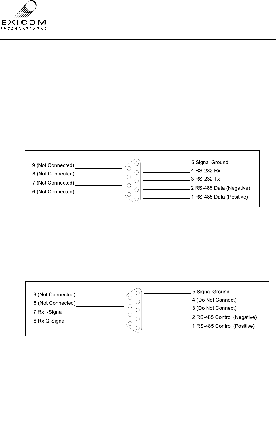
EX7100 Technical Manual - Appendix A
©1999 Exicom Technologies (1996) Ltd A-1 Issue 2 – February 2001
Appendix A
Connector Pin Information
A.1 LMS
This 9-pin (DB9) socket allows connection of the ELMS Link Management system, as well
as networking of multiple terminals via the system’s RS-485 Bus.
A.2 Control
This 9-pin (DB9) socket is used in repeater configuration, to connect two EX7100
terminals back-to-back. Note: Incorrect use of this connector will cause the EX7100 to fail.
Use only as directed.
Note: Connecting pins 6 and 7 to two channels of an oscilloscope, set in XY mode, will
allow monitoring of the received demodulated QAM constellation.
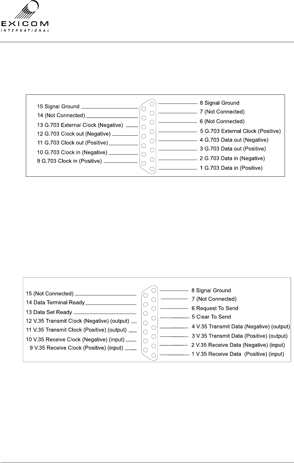
EX7100 Technical Manual - Appendix A
©1999 Exicom Technologies (1996) Ltd A-2 Issue 2 – February 2001
A.3 G.703
Provides a 120-ohm connection for 64kbps co-directional G.703 Digital Data, using a 15-
pin DB15 socket.
A.4 Synchronous Data
Provides connection of 64kbps synchronous V.35 Digital Data, via a 15-way (DB15)
socket.
Refer to Section A.7 for V.35 interface adapter cable details.
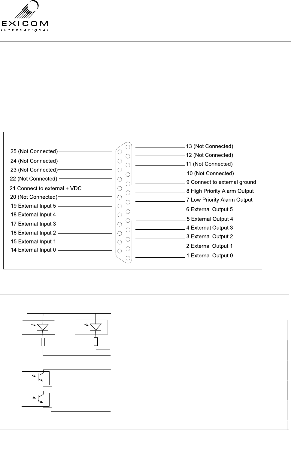
EX7100 Technical Manual - Appendix A
©1999 Exicom Technologies (1996) Ltd A-3 Issue 2 – February 2001
A.5 Input/Output
A DB25 connector provides six input/output open-collector contacts for connection of
externally generated site alarms, as well as high and low priority alarm outputs for
internal system alarms.
Note: This port uses TTL signal levels. Failure to comply with these levels may cause
damage to the EX7100.
Note: All inputs and outputs are floating.
Figure A-5 I/O circuit detail.
Optocoupler Optocoupl er
Pin 21 Connect to 8 -15 VDC
Pin 14 Input 0
Pin 19 Input 5
I/O DB25Inside EX7100
Optocoupler
Optocoupler
Pin 1 Output 0
Pin 6 Output 5
Pin 9 Connect to external ground
560 ohms 560 ohms
Optocouplers Sharp PC3Q67Q
Diode (LED) Forward Voltage: Typically 1.2 V
Diode (LED) Forward Current: Typically 20mA (min 3mA)
Transistor V
CEO
max: 35 Volts
Max I
C
: 50mA driven here for max of 7mA.
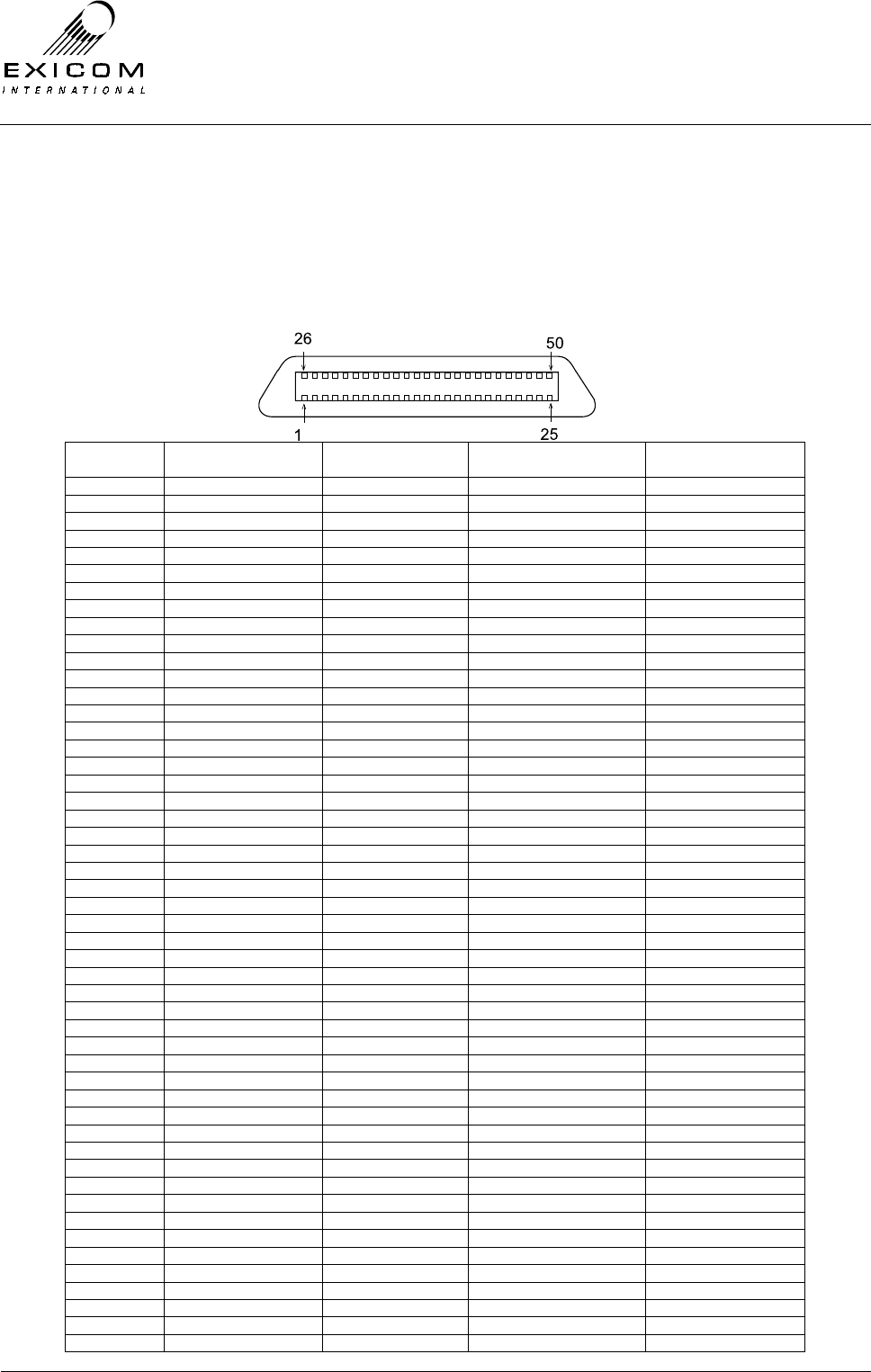
EX7100 Technical Manual - Appendix A
©1999 Exicom Technologies (1996) Ltd A-4 Issue 2 – February 2001
A.6 Line Interface
The 50-way Champ socket is internally wired to allow for any of the three terminal
configurations (2-wire Exchange, 4-wire Exchange, and Subscriber). The table below
shows pin allocation and interface cable wire colours for the three variants.
Note: The colour indicated first is the main wire colour, the colour indicated second is the
stripe.
Pin
Number Cable wire colour 2-wire Exchange
(A - Tip, B - Ring) 4-wire+E&M Exchange Subscriber
(A - Tip, B - Ring)
1 Blue/White Channel 1 (B-leg) - Channel 1 (B-leg)
2 Orange /White - Channel 1IN (B) -
3 Green/White - Channel 1 OUT (B) -
4 Brown/White - Channel 1 M-wire -
5 Slate/White Channel 2 (B-leg) - Channel 2 (B-leg)
6 Blue/Red - Channel 2 IN (B) -
7 Orange/Red - Channel 2 OUT (B) -
8 Green/Red - Channel 2 M-wire -
9 Brown/Red Channel 3 (B-leg) - Channel 3 (B-leg)
10 Slate/Red - Channel 3 IN (B) -
11 Blue/Black - Channel 3 OUT (B) -
12 Orange/Black - Channel 3 M-wire -
13 Green/Black Channel 4 (B-leg) - Channel 4 (B-leg)
14 Brown/Black - Channel 4 IN (B) -
15 Slate/Black - Channel 4 OUT (B) -
16 Blue/Yellow - Channel 4 M-wire -
17 Orange/Yellow Channel 5 (B-leg) - Channel 5 (B-leg)
18 Green/Yellow - Channel 5 IN (B) -
19 Brown/Yellow - Channel 5 OUT (B) -
20 Slate/Yellow - Channel 5 M-wire -
21 Blue/Violet Channel 6 (B-leg) - Channel 6 (B-leg)
22 Orange/Violet - Channel 6 IN (B) -
23 Green/Violet - Channel 6 OUT (B) -
24 Brown/Violet - Channel 6 M-wire -
25 Slate/Violet Ground Ground Ground
26 White/Blue Channel 1 (A-leg) - Channel 1 (A-leg)
27 White/Orange - Channel 1 IN (A) -
28 White/Green - Channel 1 OUT (A) -
29 White/Brown - Channel 1 E-wire -
30 White/Slate Channel 2 (A-leg) - Channel 2 (A-leg)
31 Red/Blue - Channel 2 IN (A) -
32 Red/Orange - Channel 2 OUT (A) -
33 Red/Green - Channel 2 E-wire -
34 Red/Brown Channel 3 (A-leg) - Channel 3 (A-leg)
35 Red/Slate - Channel 3 IN (A) -
36 Black/Blue - Channel 3 Out (A) -
37 Black/Orange - Channel 3 E-wire -
38 Black/Green Channel 4 (A-leg) - Channel 4 (A-leg)
39 Black/Brown - Channel 4 IN (A) -
40 Black/Slate - Channel 4 OUT (A) -
41 Yellow/Blue - Channel 4 E-wire -
42 Yellow/Orange Channel 5 (A-leg) - Channel 5 (A-leg)
43 Yellow/Green - Channel 5 IN (A) -
44 Yellow/Brown - Channel 5 OUT (A) -
45 Yellow/Slate - Channel 5 E-wire -
46 Violet/Blue Channel 6 (A-leg) - Channel 6 (A-leg)
47 Violet/Orange - Channel 6 IN (A) -
48 Violet/Green - Channel 6 OUT (A) -
49 Violet/Brown - Channel 6 E-wire -
50 Violet/Slate Ground Ground Ground
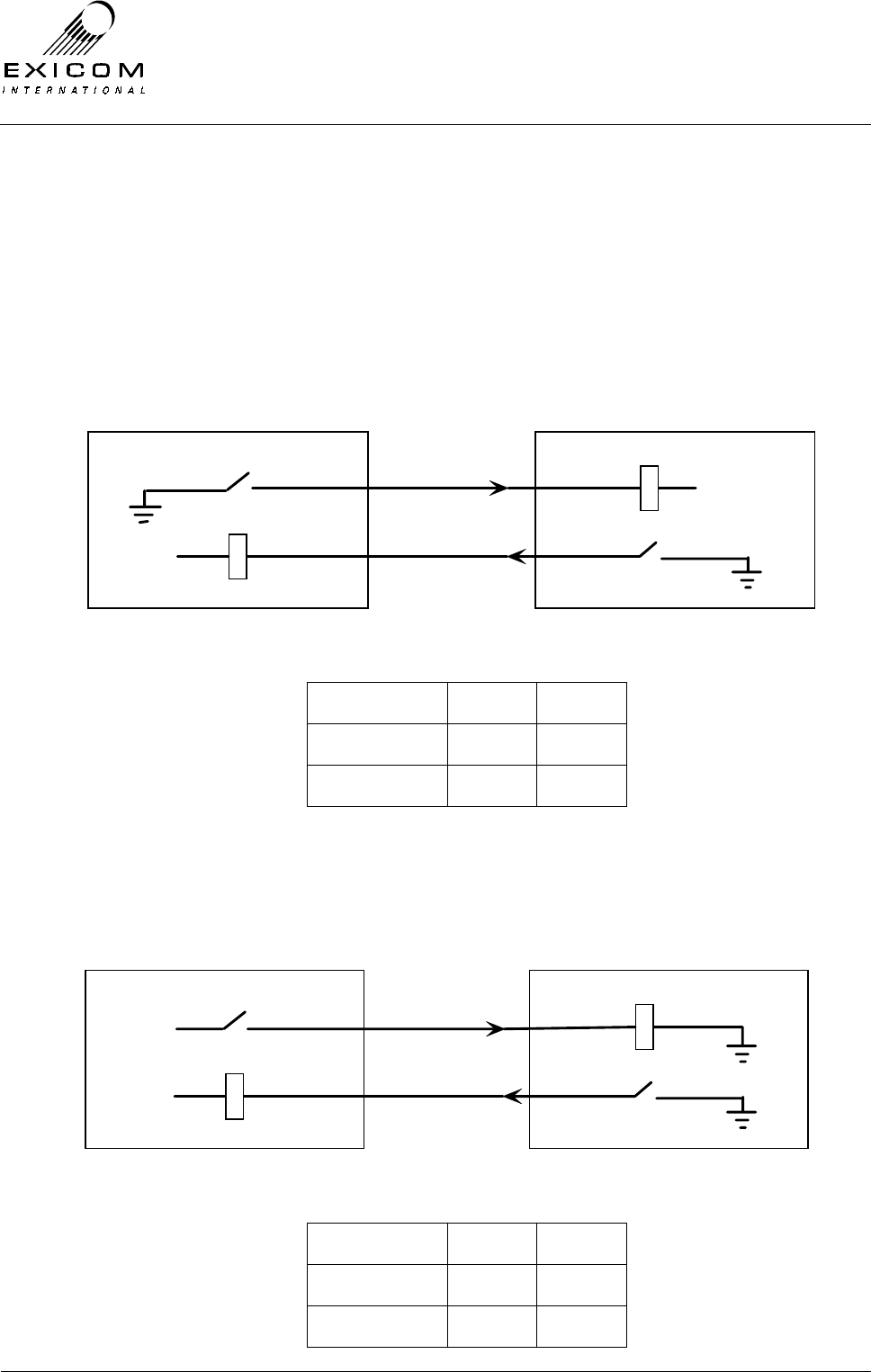
EX7100 Technical Manual - Appendix A
©1999 Exicom Technologies (1996) Ltd A-5 Issue 2 – February 2001
E & M Wire Interface Standards
The EX7100 4-Wire + E&M interface conforms to the following internationally recognised
standards. It should be noted that Exicom refers to each standard as Positive M-Wire and
Negative M-wire. Positive or Negative M-wire selection is made, via six shunts on the 4-
wire interface module.
Positive M-Wire
Condition M-wire E-wire
On-Hook Open Open
Off-Hook GND GND
Negative M-Wire
Condition M-wire E-wire
On-Hook GND Open
Off-Hook -48VDC GND
-48VDC
M WIRE
E WIRE
PABX E & M INTERFACE
RS-464 TYPE V
-48VDC
-48VDC
-48VDC
M WIRE
E WIRE
PABX E & M INTERFACE
RS-464 TYPE 1

EX7100 Technical Manual - Appendix A
©1999 Exicom Technologies (1996) Ltd A-6 Issue 2 – February 2001
A.7 Sync Data (DB15) to V.35 (M34) Interface Cable (DCE)
If required, Exicom can supply an adapter cable to provide an industry standard (M-34)
V.35 connection to user equipment.
Note: The physical specifications of V.35 are not clearly defined, and vary from one
equipment manufacturer to another. Some modifications to either Exicom’s interface
cabling, or the user equipment cabling, may be required.
Pin number
EX7100 Sync Data
Signal Description Signal Direction Pin number
V.35 (M-34F) Connector
1 Rx Data (+) ← P
2 Rx Data (-) ← S
3 Tx Data (+) → R
4 Tx Data (-) → T
5 CTS → D
6 RTS ← C
7 not used
8 Signal Ground B
9 Rx Clock (+) ← U
10 Rx Clock (-) ← W
11 Tx Clock (+) → V
12 Tx Clock (-) → X
13 DSR → E
14 DTR ← H
15 not used A-Shroud
RTS, CTS, DSR, and DTR, are generally not used in synchronous transmission. If
necessary these signals should be set to ‘On’ in the user equipment.
The following diagram shows various data clock configurations.
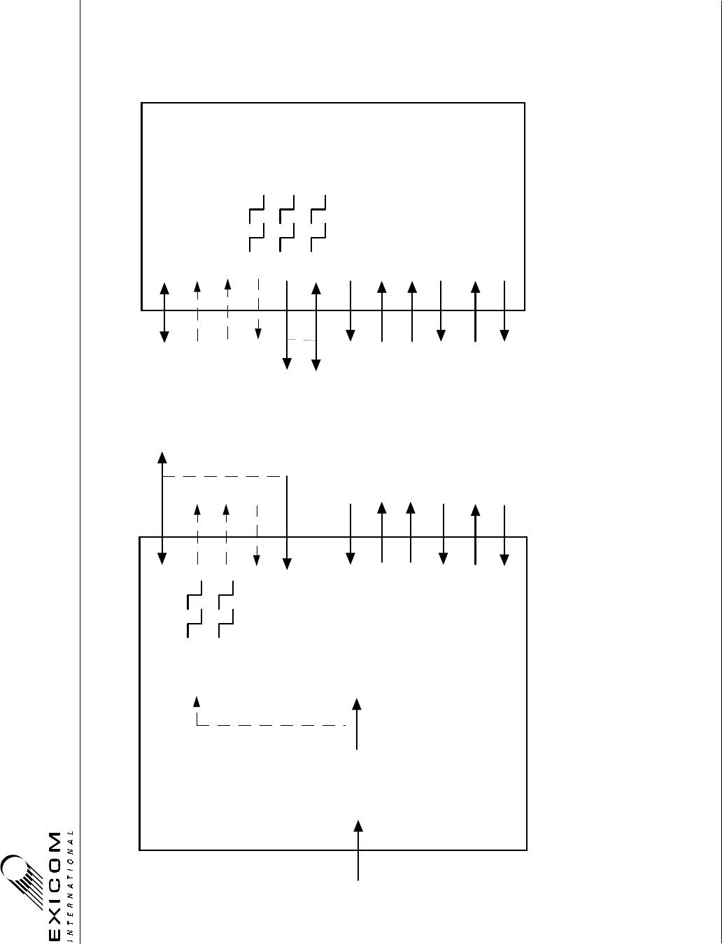
EX7100 Technical Manual - Appendix A
©1999 Exicom Technologies (1996) Ltd A-7 Issue 2 – February 2001
RF
Sync to Rx
Internal Ref
Ext Sync Clk
Tx Data
Rx Data
Rx Data Clock
Tx Data Clock
Data and Clock
from remote
terminal
EX7100
V.35 Synchronous Data Interface Configuration
Data Terminal Equipment (DTE)Data Communication Equipment (DCE)
Rx Data Clock
Tx Data Clock
Rx Data
Tx Data
Rx Data Clock
Rx Data Clock
Option 1
Option 2
Option 3
Tx Data Clk : Option 1, Sync to Rx (or Slave)
Option 2, Internal Ref (or Master)
Option 3, Ext Sync Clk
DTE Tx Data Clk (Y / AA) can be connected to DCE Rx Data Clk (U / W), in the absense of DTE Tx Clk Ext.
DCE Tx Data Clk (V / X) can be connected to DCE Rx Data Clk (U / W), should the DTE not be able to provide a clock source.
V.35 M34 Connector
V / X
Tx Clk Ext.
Rx Data Clock
Not Used
CTS
RTS
DTR
CTS
RTS
DSRDSR
DTR
U / W
Y / AA
P / S
R / T
D
C
E
H
User Mux
Rx Clock

EX7100 Technical Manual - Appendix A
©1999 Exicom Technologies (1996) Ltd A-8 Issue 2 – February 2001
This page intentionally left blank.

EX7100 Technical Manual - Appendix B
©1999 Exicom Technologies (1996) Ltd B-1 Issue 0 – May 2000
Appendix B
Options
B.1 Line Terminating Frame
The Line Terminating Frame (LTF) allows easy termination of six 2-wire circuits at both
the exchange and subscriber ends of the radio link. This rack, or wall, mounted frame is
an ideal connection point for reticulation of subscriber line cabling and may be ordered
with various termination types, as well as Primary Lightning Protection circuitry, if
required.
The LTF is based on the proven Krone modules, and is available with either:
> Standard Krone LSA terminations,
> Standard Krone LSA and Screw terminations,
> Standard Krone LSA and RJ12 terminations.
The LTF may be ordered as a stand-alone item, or may be factory wired into the EX7100
Line Interface cable.
Primary Lightning Protection
Although the EX7100 Terminal has built-in secondary protection, Exicom strongly advises
that Primary Lightning Protection be incorporated into any system design.
The LTF is capable of housing the Krone ‘Comprotect’ range of Lightning protection
modules. These modules provide protection of individual circuits, reducing the cost of
other, 10-pair, module systems.
Exicom offers the choice of two protection modules, one giving a simple Gas Arrester
level of protection, and the other giving 5-point solid-state protection.
Both modules simply plug in to the LTF, and are easily replaced once activated.
Note: The LTF requires a solid earth connection to the same point as the earth
connection between the EX7100 terminal and the equipment rack. An earth
termination is provided within the LTF.
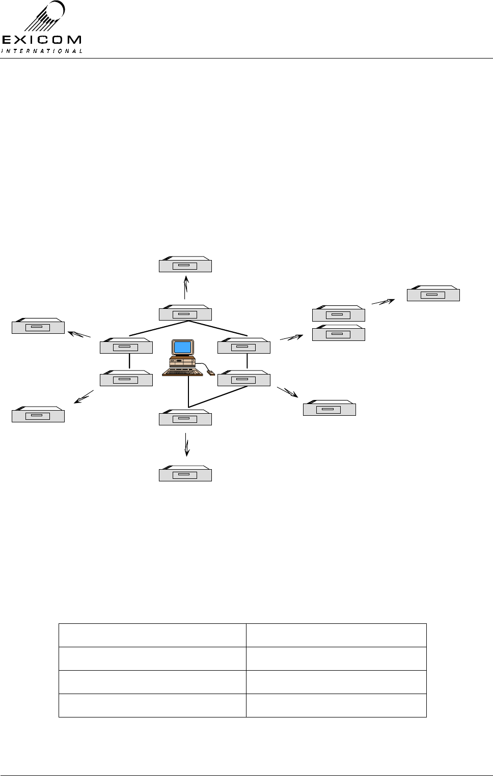
EX7100 Technical Manual - Appendix B
©1999 Exicom Technologies (1996) Ltd B-2 Issue 0 – May 2000
B.2 ELMS (Exicom Link Management System)
ELMS is a software program designed to make monitoring and configuration of single and
multiple EX7100 terminals easier for the user. ELMS operates on a Windows 95 or
Windows NT platform. It enables the user to access local and remote EX7100 terminals.
Terminal configurations can be downloaded, modified, and uploaded again.
ELMS also provides the user with a more extensive alarm monitoring system than is
available through the EX7100 terminal alone. By leaving an ELMS configured PC
connected to a network of EX7100 links, the PC can act as an alarm monitoring station
for the whole network.
ELMS: Link Management
ELMS interfaces to the EX7100 terminal through the LMS connector on the rear panel.
Circuitry converts the internal RS-485 control protocol to RS-232 for easy connection to a
PC serial port via an adapter cable.
This adapter cable can be easily made using a shielded pair wire.
Adapter cable Pinout connections:
LMS Port (DB-9) PC Serial Port (DB-9)
3 3
4 2
5 5
Warning: Do not terminate any other pins!
EX7100
EXICOM
o o
o o
o o
o
oEX7100
EX7100
EXICOM
o o
o o
o o
o
oEX7100
EX7100
EXICOM
o o
o o
o o
o
oEX7100
EX7100
EXICOM
o o
o o
o o
o
oEX7100
EX7100
EXICOM
o o
o o
o o
o
oEX7100
EX7100
EXICOM
o o
o o
o o
o
oEX7100
EX7100
EXICOM
o o
o o
o o
o
oEX7100
EX7100
EXICOM
o o
o o
o o
o
oEX7100
EX7100
EXICOM
o o
o o
o o
o
oEX7100
EX7100
EXICOM
o o
o o
o o
o
oEX7100
EX7100
EXICOM
o o
o o
o o
o
oEX7100
EX7100
EXICOM
o o
o o
o o
o
oEX7100
RS-485
EX7100
EXICOM
o o
o o
o o
o
oEX7100
EX7100
EXICOM
o o
o o
o o
o
oEX7100
Repeater