Exmark Ultra Vac Lazer As Users Manual
!! Exmark-31 Exmark Lawn Mower Manuals - Lawn Mower Manuals – The Best Lawn Mower Manuals Collection
LAZER AS to the manual 256ce70a-ea8f-4592-aaf5-e41d6f025a2e
2015-02-04
: Exmark Exmark-Exmark-Ultra-Vac-Lazer-As-Users-Manual-366901 exmark-exmark-ultra-vac-lazer-as-users-manual-366901 exmark pdf
Open the PDF directly: View PDF ![]() .
.
Page Count: 28

ULTRAV AC®
LAZERZ®AND
LAZERZ®ASMODELS
ForUltraVacSerialNos.
790,000&Higher
(TotLazerZ(LZZ)and
LazerZAS(LZAS)Units
SerialNos.790,000&Higher)
PartNo.4500-511Rev.A

Exmarkreservestherighttomakechangesor
addimprovementstoitsproductsatanytime
withoutincurringanyobligationtomakesuch
changestoproductsmanufacturedpreviously.
Exmark,oritsdistributorsanddealers,accept
noresponsibilityforvariationswhichmaybe
evidentintheactualspecicationsofitsproducts
andthestatementsanddescriptionscontained
inthispublication.
©2009—ExmarkMfg.Co.,Inc.
IndustrialParkBox808
Beatrice,NE683102
Contactusatwww.Exmark.com.
PrintedintheUSA
AllRightsReserved
Introduction
CONGRATULATIONSonthepurchaseofyour
ExmarkUltraVac.Thisproducthasbeencarefully
designedandmanufacturedtogiveyouamaximum
amountofdependabilityandyearsoftrouble-free
operation.
Thismanualcontainsoperating,maintenance,
adjustment,andsafetyinstructionsforyourExmark
UltraVac
BEFOREOPERATINGYOURMOWER,
CAREFULLYREADTHISMANUALINITS
ENTIRETY.
Byfollowingtheoperating,maintenance,andsafety
instructions,youwillprolongthelifeofyourUltra
Vac,maintainitsmaximumefciency,andpromote
safeoperation.
Ifadditionalinformationisneeded,orshouldyou
requiretrainedmechanicservice,contactyour
authorizedExmarkequipmentdealerordistributor.
AllExmarkequipmentdealersanddistributorsare
keptinformedofthelatestmethodsofservicing
andareequippedtoprovidepromptandefcient
serviceintheeldorattheirservicestations.They
carryamplestockofservicepartsorcansecurethem
promptlyforyoufromthefactory.
AllExmarkpartsarethoroughlytestedandinspected
beforeleavingthefactory,however,attentionis
requiredonyourpartifyouaretoobtainthefullest
measureofsatisfactionandperformance.
Wheneveryouneedservice,genuineExmarkparts,
oradditionalinformation,contactanAuthorized
ServiceDealerorExmarkCustomerServiceandhave
themodelandserialnumbersofyourproductready.
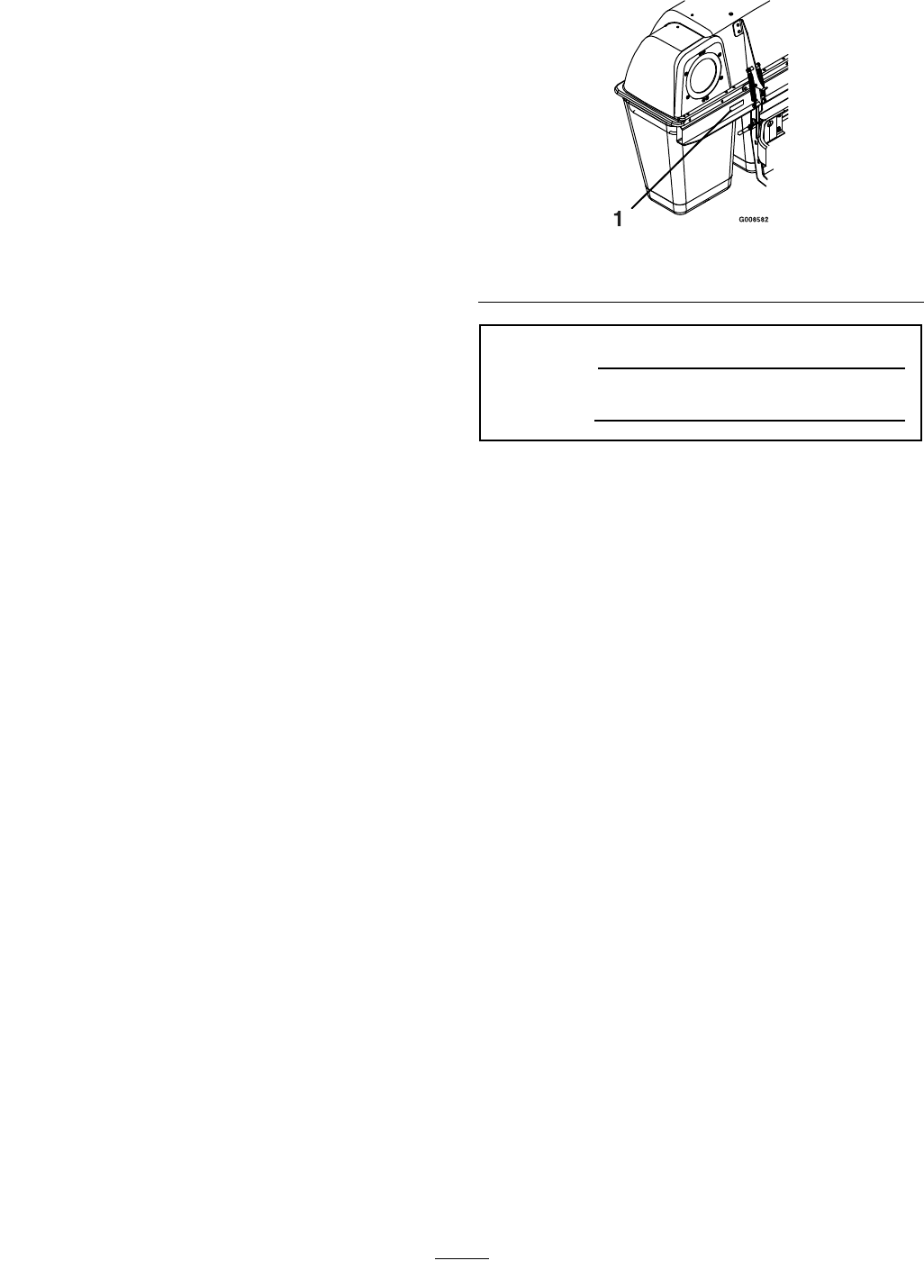
Figure1identiesthelocationofthemodelandserial
numbersontheproduct.Writethenumbersinthe
spaceprovided.
Figure1
1.Modelandserialnumberlocation
ModelNo.
SerialNo.
3

Contents
Introduction...........................................................3
Safety.....................................................................5
SafetyAlertSymbol.........................................5
SafeOperatingPractices..................................5
SafetyandInstructionalDecals.......................8
Specications.......................................................10
ModelNumbers............................................10
Systems.........................................................10
Dimensions...................................................10
TorqueRequirements....................................10
ProductOverview................................................11
Operation.............................................................11
Pre-Start........................................................11
OperatingInstructions..................................11
Transporting.................................................17
Maintenance.........................................................20
RecommendedMaintenanceSchedule(s)...........20
PeriodicMaintenance.......................................20
CheckBlowerHousing/Impeller...................20
CheckBags....................................................20
CheckExhaustDiverter.................................21
LubricateGreaseFittings...............................21
CheckConditionofBelt................................21
Adjustments.....................................................21
AdjustingtheBlowerDriveBelt
Position.....................................................21
Cleaning...........................................................22
CleanMuferandRearFrameArea................22
CleanRearScreenInHopper.........................22
CleanBlower.................................................22
Troubleshooting...................................................23
4
Safety
Safety
SafetyAlertSymbol
ThisSafetyAlertSymbol(Figure2)isusedbothin
thismanualandonthemachinetoidentifyimportant
safetymessageswhichmustbefollowedtoavoid
accidents
Thissymbolmeans:ATTENTION!BECOME
ALERT!YOURSAFETYISINVOLVED!
Figure2
1.Safetyalertsymbol
Thesafetyalertsymbolappearsaboveinformation
whichalertsyoutounsafeactionsorsituations
andwillbefollowedbythewordDANGER,
WARNING,orCAUTION.
DANGER:Whitelettering/Redbackground.
Indicatesanimminentlyhazardoussituationwhich,if
notavoided,Willresultindeathorseriousinjury.
WARNING:Blacklettering/Orangebackground.
Indicatesapotentiallyhazardoussituationwhich,if
notavoided,Couldresultindeathorseriousinjury.
CAUTION:Blacklettering/Yellowbackground.
Indicatesapotentiallyhazardoussituationwhich,if
notavoided,Mayresultinminorormoderateinjury.
Thismanualusestwootherwordstohighlight
information.Importantcallsattentiontospecial
mechanicalinformationandNoteemphasizes
generalinformationworthyofspecialattention.
SafeOperatingPractices
Training
•ReadthetractorandUltraVacOperator’sManuals
andothertrainingmaterial.Iftheoperator(s)or
mechanic(s)cannotreadEnglishitistheowner’s
responsibilitytoexplainthismaterialtothem.
•Becomefamiliarwiththesafeoperationofthe
equipment,operatorcontrols,andsafetysigns.
•Alloperatorsandmechanicsshouldbetrained.
Theownerisresponsiblefortrainingtheusers.
•Neverletchildrenoruntrainedpeopleoperate
orservicetheequipment.Localregulationsmay
restricttheageoftheoperator.
•Theowner/usercanpreventandisresponsible
foraccidentsorinjuriesoccurringtohimselfor
herself,otherpeopleorproperty.
Preparation
•Evaluatetheterraintodeterminewhataccessories
andattachmentsareneededtoproperlyandsafely
performthejob.Onlyuseonmachinesapproved
byExmark.
•Wearappropriateclothingincludingsafetyglasses,
substantialfootwear,longtrousers,andhearing
protection.DoNotoperatewhenbarefootor
whenwearingopensandals.
CAUTION
Thismachineproducessoundlevelsin
excessof85dBAattheoperator’searand
cancausehearinglossthroughextended
periodsofexposure.
Wearhearingprotectionwhenoperatingthis
machine.
•Inspecttheareawheretheequipmentistobe
usedandremoveallrocks,toys,sticks,wires,
bones,andotherforeignobjectswhichcanbe
thrownbythemachineandmaycausepersonal
injurytotheoperatororbystanders.
Operation
•Operateonlyindaylightorgoodarticiallight,
keepingawayfromholesandhiddenhazards.
•Nevermowwiththedischargedeectorraised,
removedoralteredunlessthereisagrass
collectionsystemormulchkitinplaceand
workingproperly.
5

Safety
DANGER
Therearerotatingbladesintheblowerand
underthemowerdeck.Bladecontactcan
causeseriousoperatororbystanderinjury
orevendeath.
•DoNotreachintoblowerunlessrotation
indicatorhasstopped.DisengagePTO,
stopengine,removekey,waitforall
movingpartstostop.Engageparking
brake.
•Neveroperatemowerunlessdischarge
deector,entiregrasscollectionsystem,
ormulchkitisinstalled.
•Stopengine,waitforallmovingpartstostop,
removekeyandengageparkingbrake:
–Beforechecking,cleaningorworkingonthe
mower.
–Afterstrikingaforeignobjectorabnormal
vibrationoccurs(inspectthemowerfor
damageandmakerepairsbeforerestarting
andoperatingthemower).
–Beforeclearingblockages.
–Wheneveryouleavethemower.
WARNING
Hands,feet,hair,clothing,oraccessoriescan
becomeentangledinrotatingparts.Contact
withtherotatingpartscancausetraumatic
amputationorseverelacerations.
•DoNotoperatethemachinewithout
guards,shields,andsafetydevicesin
placeandworkingproperly.
•Keephands,feet,hair,jewelry,orclothing
awayfromrotatingparts.
•Stoptheblades,slowdown,andusecautionwhen
crossingsurfacesotherthangrassandwhen
transportingthemowertoandfromtheareato
bemowed.
•Beawareofthemowerdischargepathanddirect
dischargeawayfromothers.
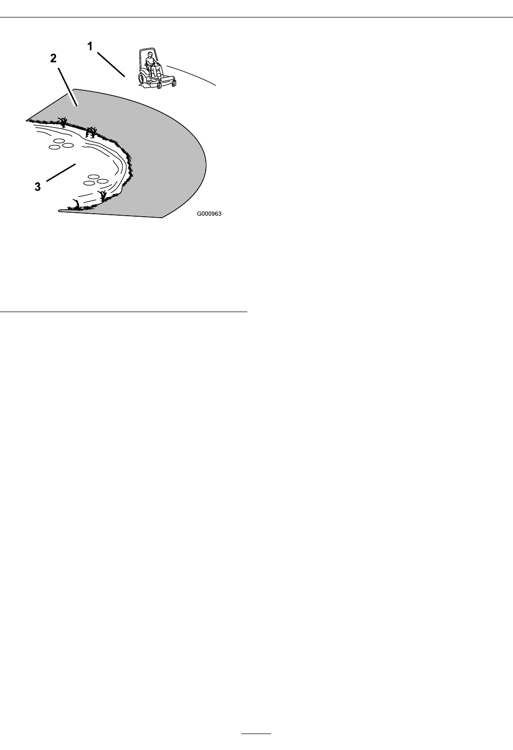
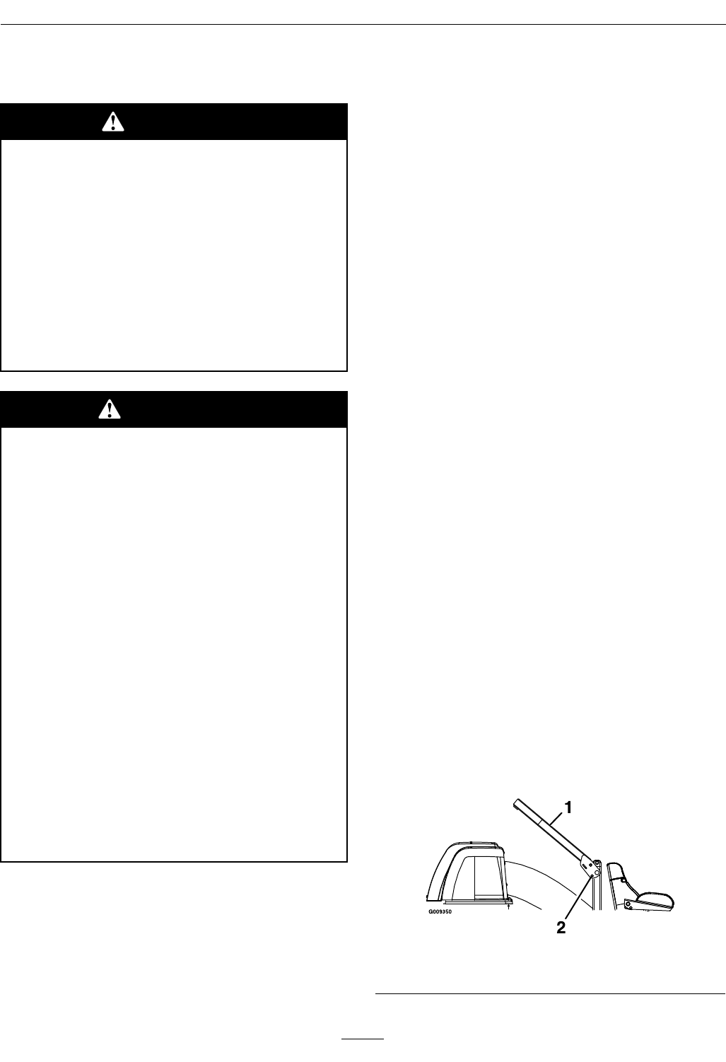
SlopeOperation
UseExtremecautionwhenmowingand/orturning
onslopesaslossoftractionand/ortip-overcould
occur.Theoperatorisresponsibleforsafeoperation
onslopes.
DANGER
Operatingonwetgrassorsteepslopescan
causeslidingandlossofcontrol.Wheels
droppingoveredges,ditches,steepbanks,or
watercancauserollovers,whichmayresult
inseriousinjury,deathordrowning.
•DoNotmowslopeswhengrassiswet.
•DoNotmowneardrop-offsornearwater.
•DoNotmowslopesgreaterthan15
degrees.
•Reducespeedanduseextremecaution
onslopes.
•Avoidsuddenturnsorrapidspeed
changes.
•Keeptherollbarintheraisedandlocked
positionanduseseatbelt.
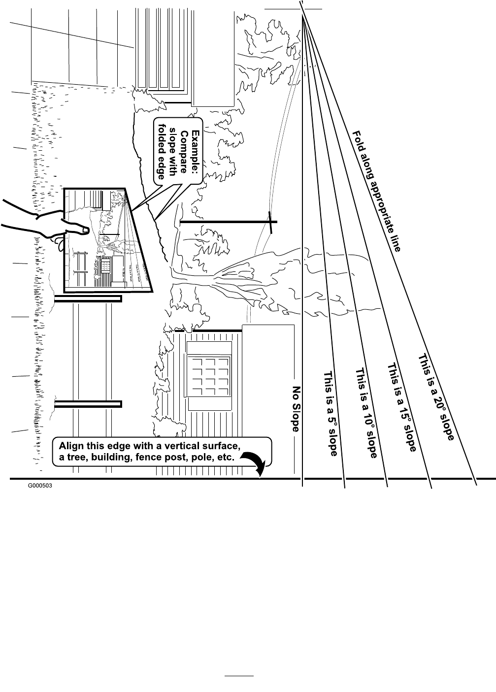
•Seeinsidethebackcovertodeterminethe
approximateslopeangleoftheareatobemowed.
•Useawalkbehindmowerand/orahandtrimmer
neardrop-offs,ditches,steepbanksorwater.
(Figure3).
6
Safety
Figure3
1.SafeZone-Usethemowerhereonslopeslessthan15
degrees
2.DangerZone-Useawalkbehindmowerand/orhand
trimmeronslopesgreaterthan15degrees,near
drop-offsandwater.
3.Water
•Removeormarkobstaclessuchasrocks,tree
limbs,etc.fromthemowingarea.Tallgrasscan
hideobstacles.
•Watchforditches,holes,rocks,dipsandrisesthat
changetheoperatingangle,asroughterraincould
overturnthemachine.
•Avoidsuddenstartswhenmowinguphillbecause
themowermaytipbackwards.
•Beawarethatoperatingonwetgrass,acrosssteep
slopesordownhillmaycausethemowertolose
traction.Lossoftractiontothedrivewheelsmay
resultinslidingandalossofbrakingandsteering.
•Alwaysavoidsuddenstartingorstoppingona
slope.Iftireslosetraction,disengagetheblades
andproceedslowlyofftheslope.
•Followthemanufacturer’srecommendationsfor
wheelweightsorcounterweightstoimprove
stability.AlwaysinstallandremovetheUltraVac,
includingcounterweights,asinstructed.Failure
todosowillcauseareductioninstabilityor
traction.DoNotoperatethemowerwithonlya
portionoftheUltraVacinstalled.
•Useextremecarewithgrasscatchersor
attachments.Thesecanchangethestabilityofthe
machineandcauselossofcontrol.Thestability
andtractionofthemachinewillchangeasthe
UltraVachopperllswithgrassclippings.Use
progressivelygreatercareonslopesasthehopper
lls.
MaintenanceandStorage
•DisengagePTO,setparkingbrake,stopengine
andremovekeyordisconnectsparkplugwire.
Waitforallmovementtostopbeforeadjusting,
cleaningorrepairing.
•Usecarewhencheckingblades.Wraptheblade(s)
orweargloves,andusecautionwhenservicing
them.Onlyreplacedamagedblades.Never
straightenorweldthem.
•Keepallguards,shieldsandallsafetydevicesin
placeandinsafeworkingcondition.
•Checkallboltsfrequentlytomaintainproper
tightness.
•Frequentlycheckforwornordeteriorating
componentsthatcouldcreateahazard.
•Allreplacementpartsmustbethesameas
orequivalenttothepartssuppliedasoriginal
equipment.
7
Safety
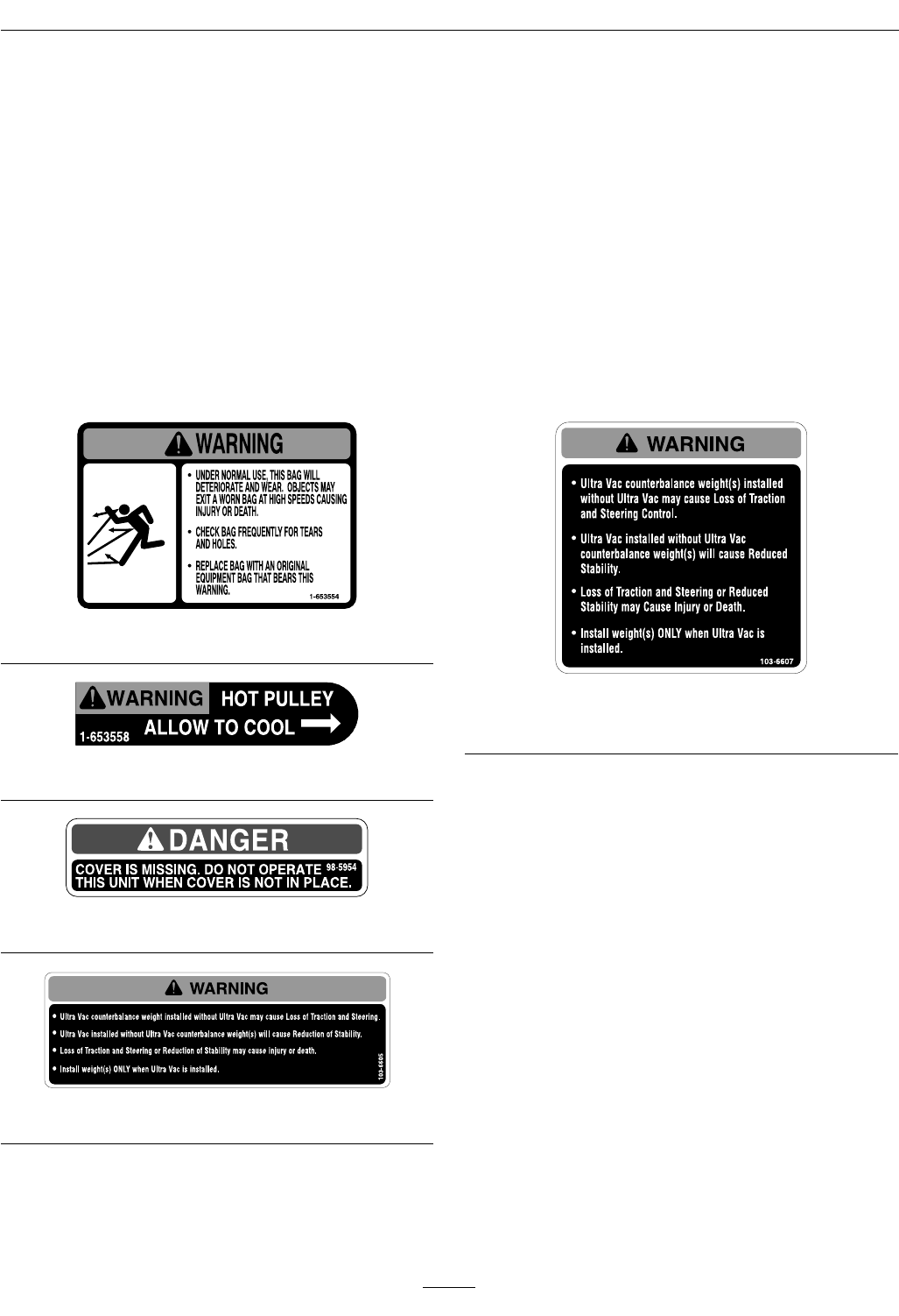
SafetyandInstructionalDecals
•Keepallsafetysignslegible.Removeallgrease,
dirtanddebrisfromsafetysignsandinstructional
labels.
•Replaceallworn,damaged,ormissingsafety
signs.
•Whenreplacementcomponentsareinstalled,be
surethatcurrentsafetysignsareafxedtothe
replacedcomponents.
•Ifanattachmentoraccessoryhasbeeninstalled,
makesurecurrentsafetysignsarevisible.
•Newsafetysignsmaybeobtainedfrom
yourauthorizedExmarkequipmentdealeror
distributororfromExmarkMfg.Co.Inc.
•Safetysignsmaybeafxedbypeelingoffthe
backingtoexposetheadhesivesurface.Apply
onlytoaclean,drysurface.Smoothtoremove
anyairbubbles.
•Familiarizeyourselfwiththefollowingsafetysigns
andinstructionlabels.Theyarecriticaltothesafe
operationofyourExmarkcommercialmower.
1-653554
1-653558
98-5954
103-6605
103-6607
LZUV3BUnitsOnly
8
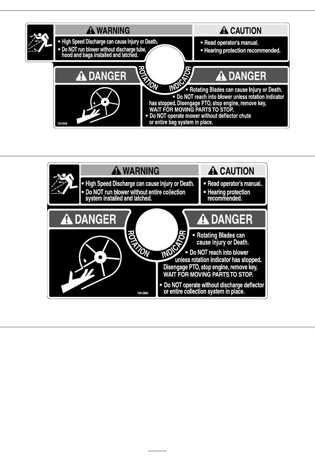
Safety
103-3508
LZUV2BUnitsOnly
109-5890
LZUV3BUnitsOnly
9

Specications
Specications
ModelNumbers
SerialNos:790,000andHigher
LZUV2B–FitsLazerZ(LZZ)andLazerZAS(LZAS)with48or52inchdeck.
LZUV3B–FitsLazerZ(LZZ)andLazerZAS(LZAS)with60or72inchdeck.
Systems
BaggingSystem
•Collectionbins:
–Commercialgrade,clothmeshbagswith
reinforcedbottoms.
–LZUV2BCapacity:8.0bushels
–LZUV3BCapacity:13.4Bushels
•DumpMechanism:Manualliftoff
•BlowerTube:Fixed,abrasionresistantmolded
polyethylene.
•Impeller:5–bladed,1/4inch(6.4mm)thick
abrasionresistantsteel,withverticalaxis.
•Impellerbearings:1inch(2.5cm)sealed
non-greaseablebearings.
Dimensions
OverallWidth:
LZUV2B
w/UltraVacQDS
LazerZw/48inchDeck62.50inches(158.8cm)
LazerZw/52inchDeck67.75inches(172.1cm)
LZUV3B
w/UltraVac
LazerZw/60inchDeck75.00inches(190.5cm)
LazerZw/72inchDeck87.25inches(221.6cm)
OverallLength:
LZUV2B
w/UltraVac
LazerZw/48inchDeck102.25inches(259.7cm)
LazerZw/52inchDeck102.25inches(259.7cm)
LZUV3B
w/UltraVac
LazerZw/60inchDeck107.00inches(271.8cm)
LazerZw/72inchDeck110.00inches(279.4cm)
CurbWeight:
LZUV2B
UltraVacWeight
Forunitsw/48inchDeck
(3toeboardweights)
309lb(140kg)
Forunitsw/52inchDeck
(2toeboardweights)
266lb(120kg)
LZUV3B
UltraVacWeight
Forunitsw/60inchDeck
(2toeboardweights)
449lb(204kg)
Forunitsw/72inchDeck
(1toeboardweights)
406lb(184kg)
TorqueRequirements
BoltLocationTorque
ImpellerSpindleBottom
Nut
55-60ft-lb(75-81N-m)
ImpellerSpindleTopNut75-80ft-lb(102-108N-m)
10
Operation
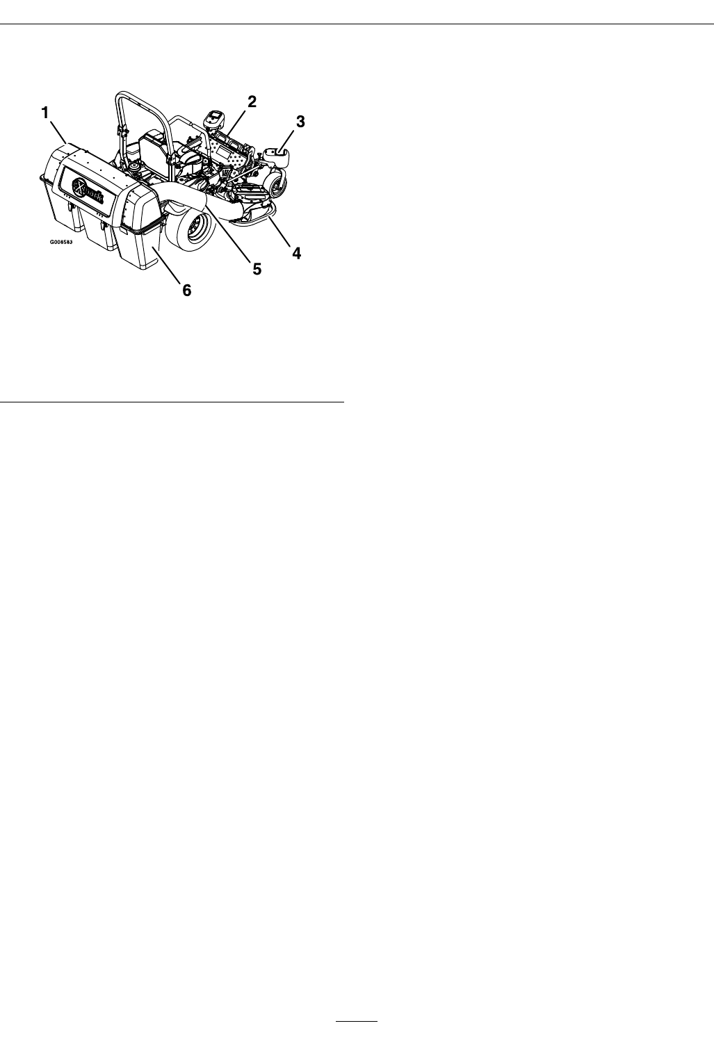
ProductOverview
Figure4
1.Hopper4.Blower
2.Toeboardweight5.Tube
3.Casterweight(LZUV3B
UnitsOnly)
6.Bag
Operation
Note:Determinetheleftandrightsidesofthe
machinefromthenormaloperatingposition.
Important:ForSerialNumbers790,000and
higher,multipleaccessoriesaddedtoabase
unitcanchangethestabilityofthemachine.
Readtheunitoperator’smanualtodetermine
ifcounterbalanceweightsarenecessaryforthe
accessoriesinstalledontheunit.
Important:Duetotheaddedweightofthe
UltraVac,itisimportanttoensuretheparking
brakeonyourmowerisadjustedproperly.Before
installingtheUltraVac,makesuretore-adjust
theparkingbrakeonyourmowerasoutlinedin
the“AdjustingtheParkingBrake”procedurein
theMaintenancesectionofthetractorOperator’s
manual.
Pre-Start
Makesureyouunderstandthecontrols,their
locations,theirfunctions,andtheirsafety
requirements.
Ensuretheblower,beltcover,bags,tubesandhopper
areingoodcondition,properlyattached,andlatched.
Important:Verifythatthereinforcedbumpers
areinstalledonyourunitpriortooperation.
RefertotheMaintenancesectionandperformallthe
necessaryinspectionandmaintenancesteps.
OperatingInstructions
Mowing
1.TheUltraVacbloweroperateswhenthePTO
isengaged.Besurethatallpersonsareclear
ofthemowerdeckbeforeengagingthecutting
blades.Setthethrottleto“midway”position.Pull
outwardonthePTOswitchtothe“ROTATE”
position.Acceleratetofullthrottletobegin
mowing.
2.TodisengagethePTO,setthethrottleto
“midway”position.PushinonthePTOswitch
tothe“STOP”positiontostopthecuttingblades
andblower.Thecuttingbladeswillrequirea
slightlylongeramountoftimetocometoa
completestopwhentheblowerisinstalledon
thedeck.Verifythatallrotationindicatorshave
11
Operation
stoppedbeforeclearingblowerassemblyor
mowerdeck.
3.Toremovethebags,rstdisengagethePTO,stop
theengineandwaitforallmovingpartstostop.
Openthehopperandremovethebagsbylifting
upontherearofthebag,thenunhookingthe
frontclip.Emptythebagsbyinvertingthem.
4.Reinstallbags,closeandlatchhopperbefore
continuingmowing.
Tipsformowingconditions:
•Whenmowinginareaswithsandysoil,use
lowliftbladesonthecuttingdeckandhigher
cuttingheightstominimizewearontheblower
components.
•Whenmowinginwetconditions,suchasjustafter
arainorinheavydew,uselowliftbladesonthe
cuttingdecktominimizepluggingoftheblower.
•Maintainingagroundspeedthatdoesnotpull
downtheengineRPMwillallowforthehighest
productivityandbestqualityofcut.Boggingthe
engineRPMdownbygoingtoofastwillcause
pluggingandqualityofcutissues.
•WhentheUltraVacgetsfull,thesoundof
theblowerwillchangeandtherewillbeslight
blowoutfromthefrontrightcornerofthedeck.
EmptyingtheUltraVacatthispointwillminimize
thepotentialforthetubetoplug.
CollectionSystemRemovalforSide
Discharge
1.Emptythehopper.
CAUTION
Thehopperassemblyisheavywhenitisfull,
whichmaymakeitdifculttoremovethe
hopperassemblyfromtheunit.Theentire
hopperassemblymayfall,whichmaycause
injury.
Priortoremovingthehopperassemblyfrom
theunit,rstemptythecontents.
2.DisengagethePTO,stopengineandwaitforall
movingpartstostop.Removekeyandengage
parkingbrake.
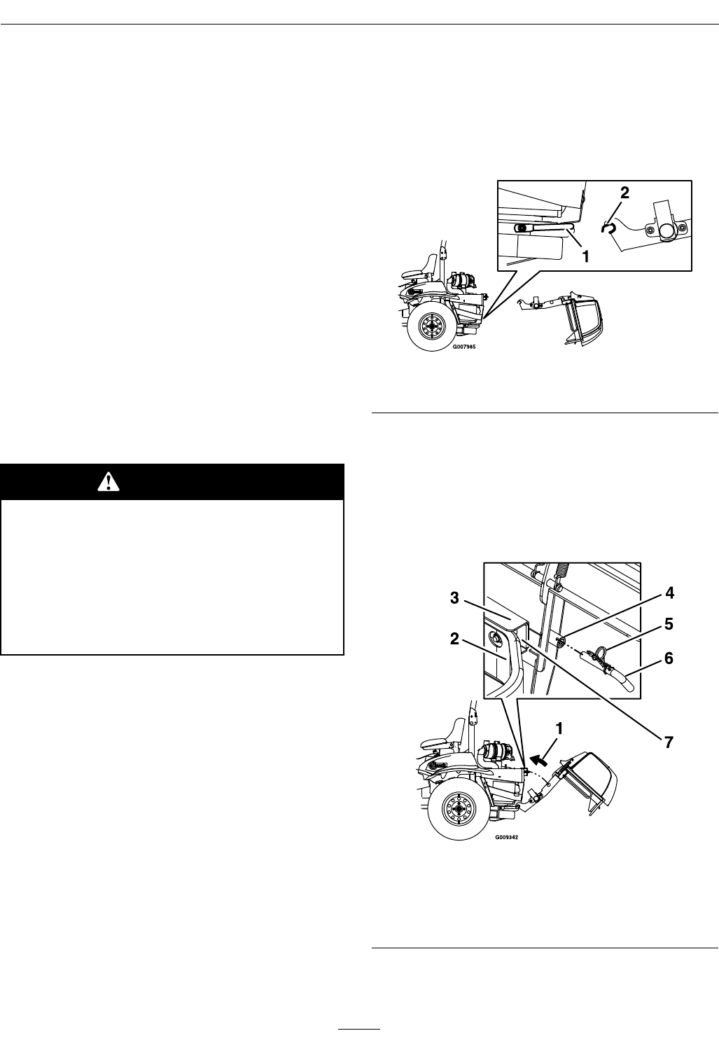
3.Removethedischargetubebyreleasingthelatches
attheblower.Slidethetubeoffthebloweroutlet
andremovetheupperendfromthehopper.
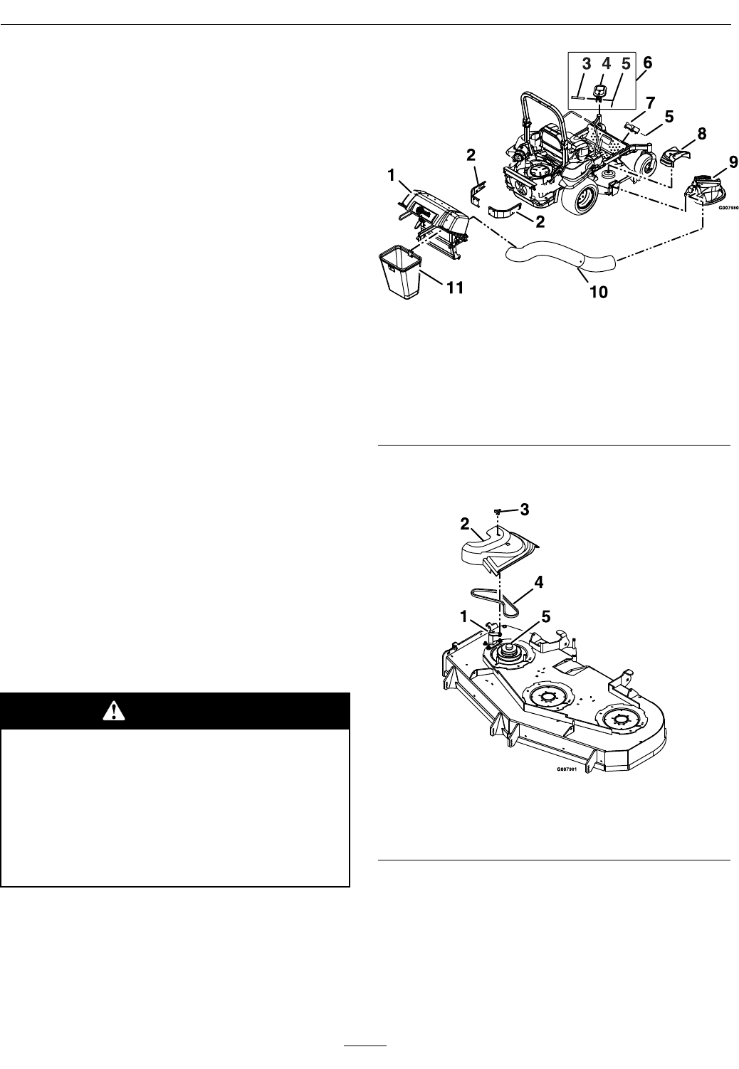
Figure5
1.Hopper7.Toeboardweight
2.Reinforcedbumpers8.Beltcover
3.Clevispin9.Blower
4.Casterarmweight10.Tubes
5.Hairpin11.Bag
6.ForLZUV3BUnitsOnly
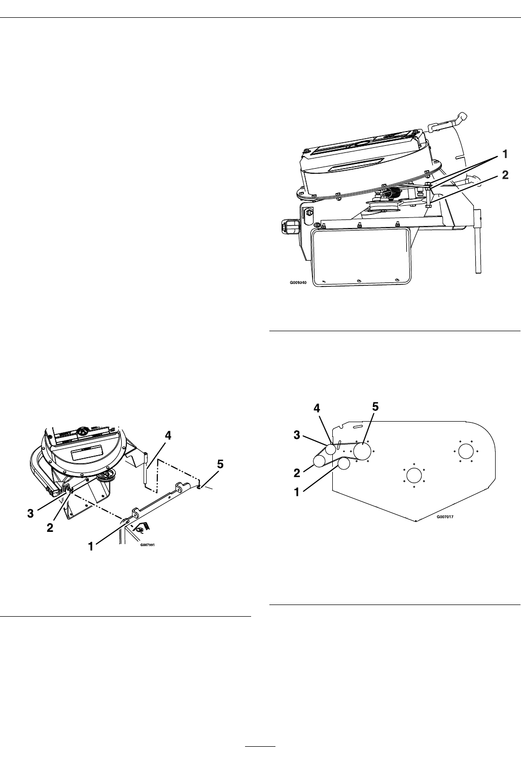
4.Removetheknobfromthebeltcoverbracketand
takeoffthebeltcover.
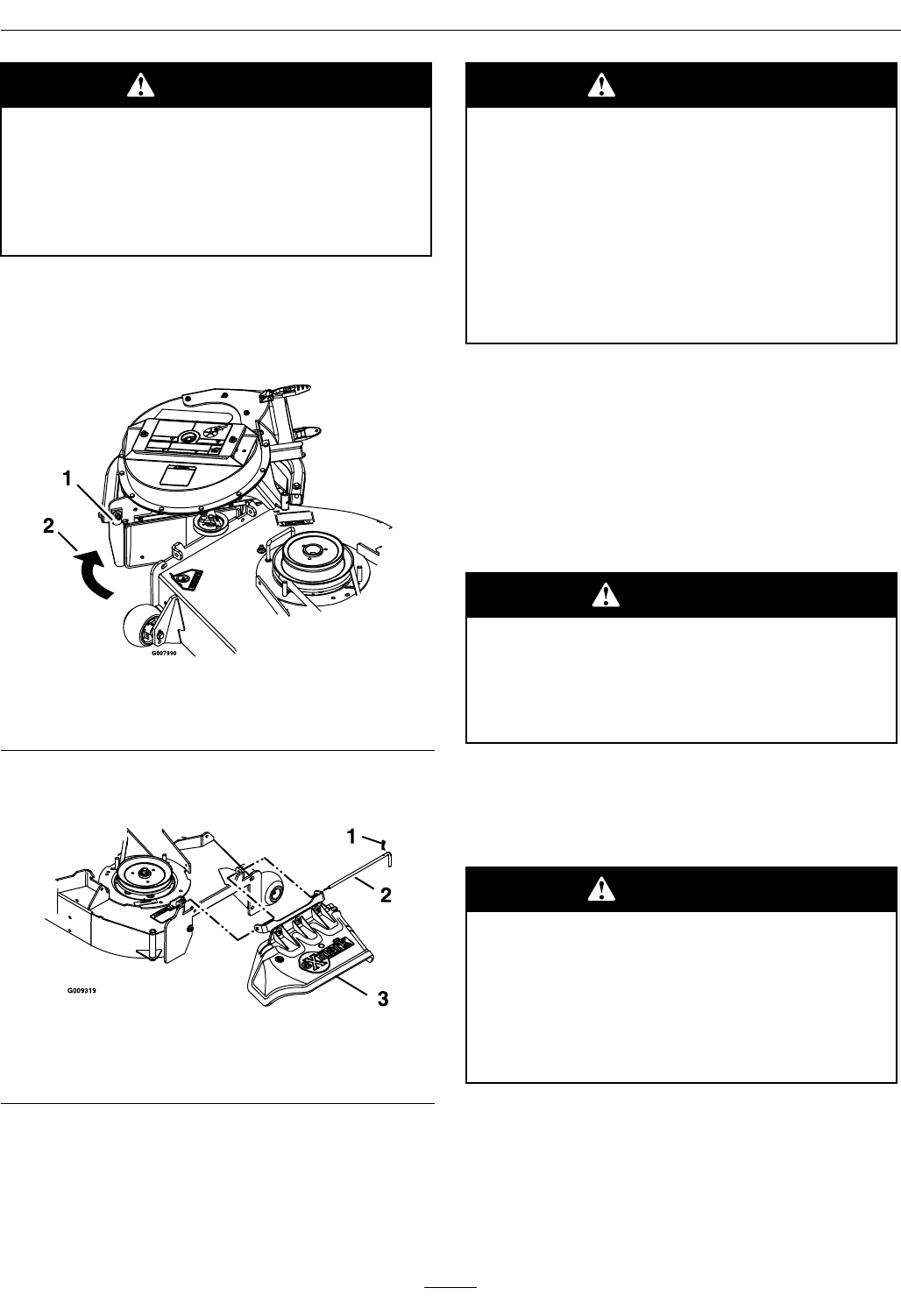
Figure6
1.Beltcoverbracket4.Belt
2.Beltcover5.Decksheave
3.Knob
12
Operation
CAUTION
Thedecksheavewillbecomeveryhot.
Touchingahotdecksheavecancausesevere
burns.
Allowthedecksheavetocoolcompletely
beforeremovingthebelt.
5.Pulltheidlerreleasehandleandremovethebelt
fromtheuppergrooveofthedecksheave.
6.Unlatchthefrontendoftheblower.Pivotthe
blowerbackandliftitoffthedeck.
Figure7
1.Blowerlatch
2.Pivotblowerawayfromdeck
7.Installthedischargedeectorusingthechute
pivotpinandhairpin(seeFigure8).
Figure8
1.Hairpin3.Dischargedeector
2.Chutepivotpin
WARNING
Anuncovereddischargeopeningwill
allowobjectstobethrowninoperator’sor
bystander’sdirection.Also,contactwith
bladecouldoccur.Thrownobjectsorblade
contactcancauseseriousinjuryorkillyou
orbystanders.
Neveroperatemowerunlessdischarge
deector,orentiregrasscollectionsystem,or
mulchkitisinstalled.
8.Re-installtheplasticbeltcoverandtightenthe
knobs.
9.Removethebagsfromthehopperassemblyby
openingthehopperandliftingupontherearof
thebagandthenunhookingthefrontclip.
10.Removethehopperassembly.DoNotusethe
exhaustdiverterasahandlewhenremovingthe
hopper.
CAUTION
Theexhaustdiverterishot.Touchingahot
exhaustdivertercancausesevereburns.
Allowtheexhaustdivertertocoolcompletely
beforeremovingthehopperassembly.
A.Pushandholdthehopperassemblytowards
theunitandpullthehairpinsandmountpins
fromframemountbarrellocatedoneachside
oftheframelegs.
WARNING
Whenthemountpinshavebeenremoved,
thehopperassemblymayfall.Afalling
hopperassemblymaycauseinjury.
Usecarewhenthemountpinsareremoved
andifnecessary,useassistancewhen
loweringthehopperassemblytotheground.
B.Ifnecessary,useassistanceandcarefullylower
thehopperassemblytotheground.
C.Re-insertthemountpinsintotheframe
mountbarrelandsecurewiththehairpin.
11.Theremovableweightsmustberemovedfrom
theunit.Toremovetheweightonthefrontof
13
Operation
thetoeboard,removethetwohairpinsthatretain
itandthenliftitfromthemountbracket.The
bracketboltedtothetoeboardremainsonthe
unit.
FortheLZUV3BUnits:Removethecaster
weightsbylooseningtheclampingknobsuntilthe
weightcanbemovedrelativetothecasterarm.
Removethehairpinsandclevispinsthathold
theweightstothecasterarms.Carefullyliftthe
weightsoffofthecasterarms.
Note:Theremovableweightsareheavy.Use
carewhenliftingthem.Makesurethatyoucan
holdthemsecurelybeforeliftingthem.Use
cautionwhenpositioningyourhandssothatyou
DoNotsetthemdownonyourhandsorngers.
Note:TheportionsoftheUltraVaccollection
systemthatarenotboltedtothemowerare
designedtobeinstalledorremovedintheir
entirety.DoNotoperatethemowerwithonlya
portionoftheUltraVacinstalled.
WARNING
Casterortoeboardweightsinstalledwithout
thecollectionsystemmaycauselossof
tractionandsteeringcontrol.Lossofcontrol
canresultinanaccidentwhichmaycause
death,injury,orpropertydamage.
InstallcasterortoeboardweightsONLY
whenthecollectionsystemisinstalled.
12.Themachinecannowbeusedforsidedischarge
mowing.
CollectionSystemInstallation
Important:Verifythatthereinforcedbumpers
areinstalledonyourunitpriortooperation.
Important:Duetotheaddedweightofthe
UltraVac,itisimportanttoensuretheparking
brakeonyourmowerisadjustedproperly.Before
installingtheUltraVac,makesuretore-adjust
theparkingbrakeonyourmowerasoutlinedin
the“AdjustingtheParkingBrake”procedurein
theMaintenancesectionofthetractorOperator’s
manual.
1.Stopengine,removekey,andwaitforallmoving
partstostop.Engageparkingbrake.
2.Removehairpinandchutepivotpin.Remove
dischargedeector.Pivotpinandhairpinmaybe
storedinthepivotholesofthedischargedeector
duringbaggingoperation.
3.Laythehopperassemblydownasshownin
Figure9.
Figure9
1.Lowerbaggermountbar2.Framenotch
4.Removethehairpinfromthemountpinandpull
themountpinoutoftheframemountbarrel.
5.Pickuptheframelegsandhookthenotchonto
thelowermountbar(seeFigure9).
6.Liftthehopperassemblyandpivotitupward
towardsthebackoftheunit(seeFigure10).
Figure10
1.Rotatehopperassembly5.Hairpin
2.Rearbumper6.Mountpin
3.Mountbracket7.Opening
4.Framemountbarrel
7.Continuetopushthehopperassemblyforward
untilitcontactsthemountbracket.
14
Operation
8.Adjusttheexhaustdiverterupordowninthe
slotssoittsoverthemufer.
9.Ifneeded,installwashersbetweentheexhaust
diverterandtheframetospacetheguardoutward.
10.Installthemountpinintotheframemount
barrel.Makesurethatitextendsintotheopening
betweentherearbumperandthemountbracket
(seeFigure10).
11.Aligntheholesinthemountpinandframe
mountbarrelandinsertthehairpintolockthe
hopperassemblyintoplace.
12.Tightenthehardwareontheexhaustdiverter.
13.Raisethehopperandinstallthebagassembliesby
insertingthehookportionintotheslotsinthe
baggersupportrods.
14.Removethebeltcoverontherightsideofthe
deck.
15.Mountthebloweronthedeckbyinsertingthe
mountingpinintothetubeweldedtotherear
cornerofthedeck(seeFigure11).Pivotthe
bloweruntilthefrontpinengagestheslotin
thedeck.Adjustthepositionofthefrontpin
ifnecessarytoengagetheslot.Usethelatches
tolocktheblowerinthisposition.Adjustthe
tensiononthelatchtoholdthebloweruptothe
deck,yetallowforreleasebyhand.
Figure11
1.Slot4.Mountingpin
2.Frontpin5.Decktube
3.Blowerlatch
16.BeltInstallation:
ForSmallDecks:
A.Slipthebeltovertheimpellersheaveonthe
blower.
Note:Itmaybeeasiertoinstallthebeltif
thebeltguideistemporarilyshiftedtoone
sideortemporarilyremoved.Eitherloosen
orremovebothnutsonthetopandbottom
ofthebeltguide.Oncethebeltisinstalled
ontheimpellersheave,reinstallthebeltguide
andtightenallhardware.
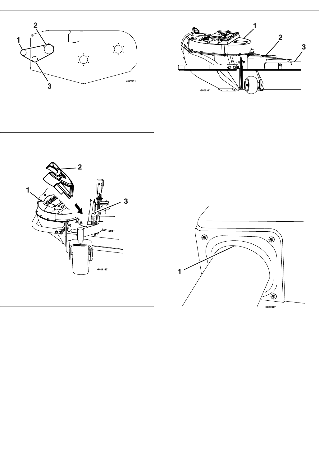
Figure12
1.Nut2.Beltguide
B.Pullthespringloadedidlerreleasehandle
backandinstallthebeltintheuppergroove
ofthetopspindlesheave.Thebeltshouldbe
routedasshowninFigure13.
Figure13
SmallDecks—ViewfromT opofBlower
1.Springloadedidler4.Beltguide
2.Impellersheave5.Decksheave
3.Fixedidler
ForLargeDecks:
Pullthespringloadedidlerbackandslipthebelt
overthetopdecksheave.
15
Operation
Figure14
LargeDecks—ViewfromT opofBlower
1.Impellersheave3.Springloadedidler
2.Decksheave
17.Positionthebeltcoveratanangleandslideit
underthemowerframe(seeFigure15).
Figure15
1.Blower3.Mowerframe
2.Beltcover
18.Pushdownonthebackofthecoverandslideit
backwardsundertheblower.
19.Slidethebeltcoverforwarduntilitisseatedunder
bothlipsonthedeck.
Figure16
1.Blower3.Decklip
2.Beltcover
20.Installtheknobanditshardware.
21.Sliptheupperandthelowertubestogether.
22.Inserttheuppertubeintothehopperseal–
pushinthenpulloutsothatthesealisextended
outward.
23.Alignthedimpleontheuppertubewiththeend
ofhoppersealandcenterbetweenthetwoscrews
asshowninFigure17.
Figure17
1.Dimple
24.Setthedeckinlowestcuttingposition.
25.Slidethelowertubeontotheblowerandattach
thelatches.(Makesurethattheuppertubedoes
notmoveoutofalignment).
26.Ifthelowertubeisreplaced,drillthree7/32inch
holesinthelowertubeusingtheuppertubeholes
asreference.SeeFigure18.
27.Removethetubesfromunitandassemblethe
upperandthelowertubesusingthree#10-24
x3/4inchhexwasherheadscrews,three#10
washers,andthree#10-24nylocnuts.Thescrew
headshouldbeinstalledtotheinsideofthe
16
Operation
tubetoprovideminimumobstructiontoow .
Makesurethattheupperandthelowerendsare
orientedproperlyasthetubesareassembled.
(Partinglinesshouldroughlybelinedup.)
Figure18
1.Drilltheholeshere
28.Slidethelowerendofthetubeassemblyoverthe
bloweroutletandalignthenotchwiththetube
latch.Latchthetubetotheblower.
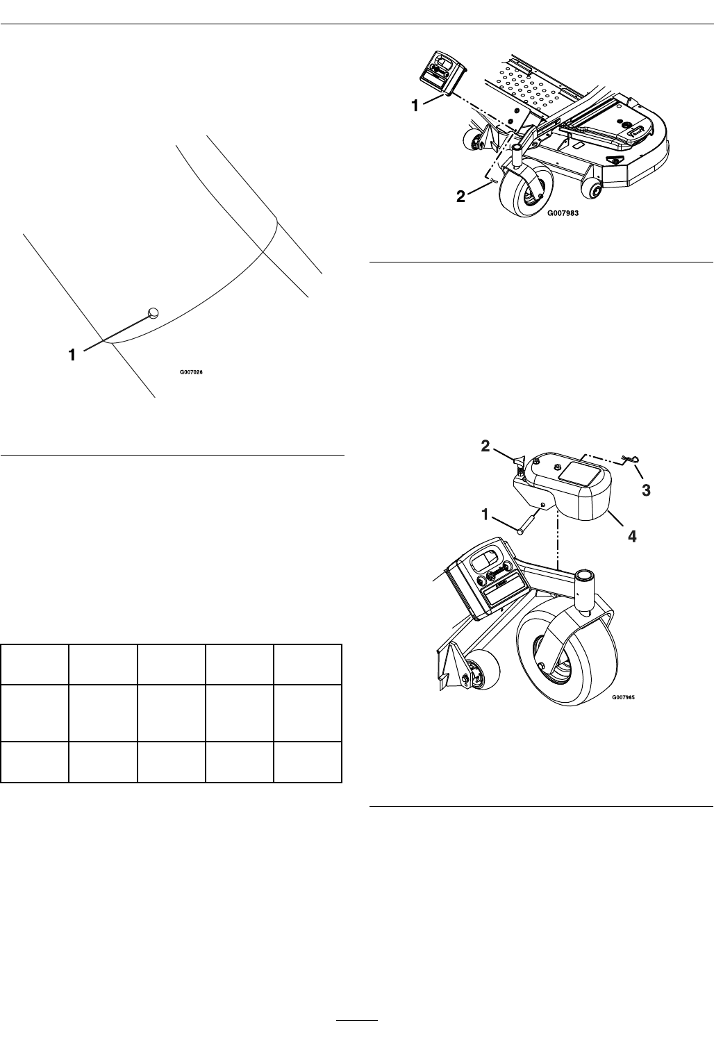
29.Installtheremovableweights.Hookthefronttoe
boardweightassemblyoverthetopoftheweight
mountingplateandsecurewithtwohairpins
Figure19).
WeightQuantities
Deck
Size
48inch52inch60inch72inch
Toe
Board
Weight
3221
Caster
Weight
——22
Note:Theremovableweightsareheavy.Use
carewhenliftingthem.makesurethatyoucan
holdthemsecurelybeforeliftingthem.Use
cautionwhenpositioningyourhandstothatyou
DoNotsetthemdownonyourhandsorngers.
Figure19
30.ForLZUV3BUnitsOnly:
A.Installtheremovablecasterweightsonthe
casterarms(seeFigure20).
B.Inserttheclevispinthroughthebrackethole
andfastenwithahairpin.
C.Tightenknobonweightassemblyuntilthe
weightisclampedsecurelytothecasterarm.
Figure20
ForLZUV3BUnitsOnly
1.Clevispin3.Hairpin
2.Knob4.Casterweight
Transporting
TransportingaUnit
Useaheavy-dutytrailerortrucktotransportthe
machine.Lockbrakeandblockwheels.Securely
fastenthemachinetothetrailerortruckwithstraps,
chains,cable,orropes.Besurethatthetrailerortruck
17
Operation
hasallnecessarylightingandmarkingasrequiredby
law .Secureatrailerwithasafetychain.
CAUTION
Thisunitdoesnothaveproperturn
signals,lights,reectivemarkings,ora
slowmovingvehicleemblem.Drivingona
streetorroadwaywithoutsuchequipment
isdangerousandcanleadtoaccidents
causingpersonalinjury.Drivingonastreet
orroadwaywithoutsuchequipmentmayalso
beaviolationofStatelawsandtheoperator
maybesubjecttotrafcticketsand/ornes.
DoNotdriveaunitonapublicstreetor
roadway.
WARNING
Loadingaunitonatrailerortruckincreases
thepossibilityofbackwardtip-over.
Backwardtip-overcouldcauseseriousinjury
ordeath.
•Useextremecautionwhenoperatinga
unitonaramp.
•Useonlyasingle,fullwidthramp;Do
Notuseindividualrampsforeachside
oftheunit.
•Ifindividualrampsmustbeused,use
enoughrampstocreateanunbroken
rampsurfacewiderthantheunit.
•DoNotexceeda15°anglebetweenramp
andgroundorbetweenrampandtrailer
ortruck.
•Avoidsuddenaccelerationwhiledriving
unituparamptoavoidtippingbackward.
•Avoidsuddendecelerationwhilebacking
unitdownaramptoavoidtipping
backward.
LoadingaUnit
DoNottransporttheunitwiththehopperfull.
Emptythehopperbeforeattemptingtoloadunit
ontrailerortruck.Thiswillreducethechance
ofrearwardtipup.Useextremecautionwhen
loadingunitsontrailersortrucks.Onefullwidth
rampthatiswideenoughtoextendbeyondtherear
tiresisrecommendedinsteadofindividualrampsfor
eachsideoftheunit.Thelowerrearsectionofthe
tractorframeextendsbackbetweentherearwheels
andservesasastopfortippingbackward.Having
afullwidthrampprovidesasurfacefortheframe
memberstocontactiftheunitstartstotipbackward.
Ifitisnotpossibletouseonefullwidthramp,use
enoughindividualrampstosimulateafullwidth
continuousramp.
Rampshouldbelongenoughsothattheangles
betweentherampandthegroundandtherampand
thetrailerortruckDoNotexceed15°.Asteeper
anglemaycausemowerdeckcomponentstoget
caughtastheunitmovesfromramptotraileror
truck.Steeperanglesmayalsocausetheunittotip
backward.Ifloadingonornearaslope,position
thetrailerortrucksoitisonthedownsideofthe
slopeandtherampextendsuptheslope.Thiswill
minimizetherampangle.Thetrailerortruckshould
beaslevelaspossible.
Important:DoNotattempttoturntheunit
whileontheramp,youmaylosecontroland
driveofftheside.
Avoidsuddenaccelerationwhendrivinguparamp
andsuddendecelerationwhenbackingdownaramp.
Bothmaneuverscancausetheunittotipbackward.
RolloverProtectionSystem(ROPS)
Therollbarhasanintermediatepositionthatallows
thebartobeloweredtoprovideoverheadclearance,
butnotrestdirectlyontheUltraVacassembly.Insert
a1/2x3inchboltand1/2inchnut(orExmark
serviceparts:clevispinP/N283-55andhairpinP/N
1-806005)intothedownstopholeoneachsideand
lowertherollbar.
Figure21
1.Intermediateposition2.Downstophole
18

Operation
Important:Therollbarisanintegraland
effectivesafetydevice.Keeptherollbarinthe
raisedandlockedpositionwhenoperatingthe
mower.Lowertherollbartemporarilyonlywhen
absolutelynecessary.
RefertotheOperator’smanualsuppliedwithyour
tractorforadditionalROPSsafetyandoperating
instructions.
19
Maintenance
Maintenance
Note:Determinetheleftandrightsidesofthemachinefromthenormaloperatingposition.
WARNING
Whilemaintenanceoradjustmentsarebeing
made,someonecouldstarttheengine.
Accidentalstartingoftheenginecould
seriouslyinjureyouorotherbystanders.
Removethekeyfromtheignitionswitch,
engageparkingbrake,andpullthewire(s)
offthesparkplug(s)beforeyoudoany
maintenance.Alsopushthewire(s)aside
soitdoesnotaccidentallycontactthespark
plug(s).
WARNING
Theenginecanbecomeveryhot.Touching
ahotenginecancausesevereburns.
Allowtheenginetocoolcompletelybefore
serviceormakingrepairsaroundtheengine
area.
RecommendedMaintenanceSchedule(s)
MaintenanceService
IntervalMaintenanceProcedure
Beforeeachuseordaily
•Checktheblowerhousing/impeller.
•Checkbags.
•Checkexhaustdiverter.
•Cleanmuferandrearframearea.
•Cleanrearscreeninthehopper.
Every25hours•Lubricategreasettings.
Every50hours•Checkconditionofbelt.
Yearlyorbeforestorage•Cleanblower.
PeriodicMaintenance
CheckBlower
Housing/Impeller
ServiceInterval:Beforeeachuseordaily
1.Stopengine,waitforallmovingpartstostop,and
removekey.Engageparkingbrake.
2.Inspectforwearordamagedaily.Replaceor
repairwornpartsasneeded
Note:Whenmowinginareaswithsandysoil,
uselowliftbladesonthecuttingdeckandhigher
cuttingheightstominimizewearontheblower
components.
CheckBags
ServiceInterval:Beforeeachuseordaily
1.Stopengine,waitforallmovingpartstostop,and
removekey.Engageparkingbrake.
2.Inspectthebagsforwear,tears,ordamage.
WARNING
Undernormalusethebagwilldeteriorate
andwear.Objectscouldexitthroughworn
bagathighspeeds.Thrownobjectscan
causeseriousinjuryorkillyouorbystanders.
Checkbagsfrequentlyfortearsandholes.
Replacewornbags.
20

Maintenance
CheckExhaustDiverter
ServiceInterval:Beforeeachuseordaily
CAUTION
Theexhaustdiverterishot.Touchingahot
exhaustdivertercancausesevereburns.
Allowtheexhaustdivertertocoolcompletely
beforeperformingmaintenance.
1.Stopengine,waitforallmovingpartstostop,and
removekey.Engageparkingbrake.
2.Inspectandremovedebrisfromtheexhaust
diverterdaily.
LubricateGreaseFittings
Note:Seechartforserviceintervals.
1.Stopengine,waitforallmovingpartstostop,and
removekey.Engageparkingbrake.
2.LubricatettingswithNGLIgrade#2
multi-purposegungrease.
Refertothefollowingchartforttinglocations
andlubricationschedule.
LubricationChart
Fitting
Locations
Initial
Pumps
Numberof
Places
Service
Interval
1.Idler
Bushings
1–2125Hours
CheckConditionofBelt
ServiceInterval:Every50hours
AllUnits
1.Stopengine,waitforallmovingpartstostop,and
removekey.Engageparkingbrake.
2.Inspectthebeltfordamageorwear.Replacebelt
withoneofthefollowing:
DeckPartNo.
48inch1-653333
52inch1-653438
60inch103-0866
72inch103-0867
Adjustments
AdjustingtheBlowerDrive
BeltPosition
1.Readtheoperator’smanualfortheUltraVac
andmowerbeforeperformingthisadjustment.
Makesurethatyouunderstandthecontrols,their
locationstheirfunctionsandsafetyrequirements.
2.Ensuretheblower,beltcover,bags,tubeand
hopperareingoodcondition,properlyattached
andlatched.
3.RuntheunitwiththePTOandtheblower
engagedfortwominutes.
4.DisengagethePTO,stoptheengineandremove
thekey.
5.Removethebeltcoverandchecktomakesure
thatthebeltisridingnearthecenteroftheat
idlerontheidlerarm.Ifthebeltisnotridingnear
thecenteroftheidler,removetheblower,and
bendtheidlerarmslightly.
6.Reinstalltheblowerandbeltcoverandperform
steps3-5againtoverifybeltposition.
21

Maintenance
Cleaning
CleanMuferandRear
FrameArea
ServiceInterval:Beforeeachuseordaily
Stopengine,waitforallmovingpartstostop,and
removekey.Engageparkingbrake.
WARNING
Operatingengineparts,especiallythe
mufer,becomeextremelyhot.Severeburns
canoccuroncontactanddebris,suchas
leaves,grass,brush,etc.cancatchre.
•Allowengineparts,especiallythemufer,
tocoolbeforetouching.
•Removeaccumulateddebrisfrommufer
andenginearea.
CleanRearScreenInHopper
ServiceInterval:Beforeeachuseordaily
1.Stopengine,waitforallmovingpartstostop,and
removekey.Engageparkingbrake.
2.Openhopperandremoveclippingsthatarestuck
tothescreen.
CleanBlower
ServiceInterval:Yearlyorbeforestorage
Grassbuildupmaycauseproblemswiththeimpeller
whentheunitisputbackintooperation.
1.Stopengine,waitforallmovingpartstostop,and
removekey.Engageparkingbrake.
2.Removegrassbuildupfromaroundtheimpeller
beforeplacingitinstorage.
22

Troubleshooting
Troubleshooting
Important:Itisessentialthatalloperatorsafetymechanismsbeconnectedandinproperoperating
conditionpriortomoweruse.
Whenaproblemoccurs,DoNotoverlookthesimplecauses.Forexample:startingproblemscouldbe
causedbyanemptyfueltank.
Thefollowingtablelistssomeofthecommoncausesoftrouble.DoNotattempttoserviceorreplacemajor
itemsoranyitemsthatcallforspecialtimingoradjustmentprocedures(suchasvalves,governor,etc.).Have
thisworkdonebyyourEngineServiceDealer.
Note:WhendisconnectingelectricalconnectorsDoNotpullonthewirestoseparatetheconnectors.
ProblemPossibleCauseCorrectiveAction
1.Cuttingblade(s)is/arebentorunbalanced.1.Installnewcuttingblade(s).
2.Blademountingboltisloose.2.Tightentheblademountingbolt.
3.Looseblowerpulleyorpulleyassembly.3.Tightentheappropriatepulley.
Abnormalvibration.
4.Blowerimpellerbladesarebent.4.ContactanAuthorizedServiceDealer.
Blowerdrivebeltsnapsorbreaksfrequently.1.Idlerarmisoutofalignment.1.Correctthealignmentoftheidlerarm.
1.Bagsarefull.1.Emptybagsmorefrequently.
2.Pluggedscreeninbaggerhopper.2.Removedebris,leavesorgrassclippings
fromthescreen.
3.Groundspeedistoofast.3.Drivesloweratfullthrottle.
4.Blowerbeltisworn,loose,orbroken.4.Installnewblowerbelt.
5.Pluggedtubeorblower.5.Locateandremovepluggeddebris.
Excessivegrassblowoutfromthedeck.
6.Conditionsaredry.6.Uselowerliftblade.
1.Bagsaretoofull.1.Emptybagsmorefrequently
2.Groundspeedistoofast.2.Drivesloweratfullthrottle.
3.Grassistoowet.3.Cutgrasswhenitisdry.
4.Grassistoolong.4.Cutgrassmorefrequentlyorathighercut
height.
5.Pluggedscreeninbaggerhopper.5.Removedebris,leaves,orgrassclippings
fromthescreen.
6.Blowerdrivebeltisworn,loose,or
broken.
6.Installnewbelt.
Blowerandtubesplugtoofrequently.
7.Blowerisplugged.7.Uselowliftbladesinwetconditions.
1.Pluggedblower.1.Removedebris,leaves,orgrassclippings
fromtheblowerimpeller.
Blowerimpellerdoesnotspinfreely.
2.Impellernotaligned.2.ContactanAuthorizedServiceDealer.
Plowingleaves.1.Deckistoolow.1.Raisethedeckslightly.
1.Blowoutfromdeck.1.Checkforcloggedtubes.
Chasingleaves.
2.Hopperisfull.2.Dumpmorefrequently.
Blowercomponentsshowsignsofwear
and/oraircleanersandcoolingnsaredirty.
1.Sandordryconditions.1.Uselowliftbladesonthecutting
deckandhighercuttingheights.
Cleanaircleanersandcoolingns
frequently.
23

Conditions and Products Covered
Exmark Mfg. Co. Inc. and its affiliate, Exmark Warranty
Company, pursuant to an agreement between them, jointly
warrant on the terms and conditions herein, that we will repair,
replace or adjust any part on these products and found by us
(in the exercise of our reasonable discretion) to be defective in
factory materials or workmanship for a period of one year.
This warranty applies to Exmark commercial attachments and
accessories sold in the U.S. or Canada. This warranty may
only be assigned or transferred to a second (or third) owner by
an authorized Exmark dealer. The warranty period commences
upon the date of the original retail purchase.
Warranty Exceptions Warranty Period
• Bags, Belts and Tires 90 days
This warranty only includes the cost of parts and labor.
Items and Conditions Not Covered
This warranty does not cover the following:
• Pickup and delivery charges to and from any authorized
Exmark Service Dealer.
• Any damage or deterioration due to normal use, wear and
tear, or exposure.
• Cost of regular maintenance service or parts, such as filters,
fuel, lubricants, tune-up parts, and adjustments.
• Any product or part which has been altered or misused or
required replacement or repair due to normal wear,
accidents, or lack of proper maintenance.
• Any repairs necessary due to use of parts, accessories or
supplies, including gasoline, oil or lubricants, incompatible
with the attachment or accessory or other than as
recommended in the operator's manual or other operational
instructions provided by Exmark.
All warranty work must be performed by an authorized
Exmark Service Dealer using Exmark approved replacement
parts.
Instructions for Obtaining Warranty Service
The product must be registered with original proof of purchase
by an Exmark Service Dealer before obtaining any warranty
service.
Contact any Exmark Service Dealer to arrange service at their
dealership. To locate a dealer convenient to you, access our
website at www.exmark.com. U.S. or Canada customers may
also call 402-223-6375.
If for any reason you are dissatisfied with the Service Dealer’s
analysis or with the assistance provided, contact us at:
Exmark Customer Service Department
The Exmark Warranty Company
2101 Ashland Avenue
Beatrice, NE 68310
402-223-6375 or
service@exmark.com
Owner’s Responsibilities
The Exmark attachment or accessory, including any defective
part, must be returned to an authorized Exmark service dealer
within the warranty period. This warranty extends only to
commercial attachments and accessories operated under
normal conditions. You must read the operator’s manual. You
must also properly service and maintain your Exmark product
as described in the operator’s manual or other operational
instructions provided by Exmark. Such routine maintenance,
whether performed by a dealer or by you, is at your expense.
General Conditions
The sole liability of Exmark and Exmark Warranty Company
with respect to this warranty shall be repair or replacement of
defective components as set forth herein. Neither Exmark
nor Exmark Warranty Company shall be liable for any
incidental or consequential loss or damage.
Such damages include but are not limited to:
• Expenses related to gasoline, oil or lubricants.
• Travel time, overtime, after hours time or other
extraordinary repair charges or charges relating to repairs or
replacements outside of normal business hours at the place
of business of the authorized Exmark Service Dealer.
• Rental of like or similar replacement equipment during the
period of any warranty, repair or replacement work.
• Any telephone or telegram charges or travel charges.
• Loss or damage to person or property other than that
covered by the terms of this warranty.
• Any claims for lost revenue, lost profit or additional cost as
a result of a claim of breach of warranty.
• Attorney's fees.
No Claim of breach of warranty shall be cause for cancellation
or rescission of the contract of sale of any Exmark attachment
or accessory.
All implied warranties of merchantability (that the
product is fit for ordinary use) and fitness for use (that the
product is fit for a particular purpose) are limited to the
duration of the express warranty.
Some states do not allow exclusions of incidental or
consequential damages, or limitations on how long an
implied warranty lasts, so the above exclusions and
limitations may not apply to you.
This warranty gives you specific legal rights, and you may
also have other rights which vary from state to state.
Exmark Commercial Attachments and Accessories
1 Year Limited Warranty
G4500-433
24

Notes:
25

ServiceRecord
Date:DescriptionofWorkDone:ServiceDoneBy:
26
27

MID-MOUNT RIDING ACCESSORIES AND OPTIONS
SEE EXMARK’S COMPLETE LINE OF ACCESSORIES AND OPTIONS
WALK-BEHIND ACCESSORIES AND OPTIONS
GRASS CATCHER
MICRO-MULCH SYSTEM
TURF STRIPER
STANDON
CUSTOM RIDE SEAT SUSPENSION SYSTEM
FULL SUSPENSION SEAT
DECK LIFT ASSIST KIT
HITCH KIT
LIGHT KIT
12V POWER PORT
MICRO-MULCH SYSTEM
OPERATOR CONTROLLED DISCHARGE
ROLL OVER PROTECTION SYSTEM (ROPS)
SUN SHADE
TRASH CONTAINER
TURF STRIPER
ULTRA VAC COLLECTION SYSTEM
ULTRA VAC QUICK DISPOSAL SYSTEM
OUT-FRONT RIDING ACCESSORIES AND OPTIONS
CUSTOM RIDE SEAT SUSPENSION SYSTEM
DUAL-TAIL WHEEL
FLOOR PAN EXTENDER
HITCH KIT
LIGHT KIT
MICRO-MULCH SYSTEM
ROLL OVER PROTECTION SYSTEM (ROPS)
SNOW BLADE
SNOWBLOWER
SUN SHADE
TRASH CONTAINER
ULTRA VAC COLLECTION SYSTEM
ULTRA VAC QUICK DISPOSAL SYSTEM
WEATHER CAB
PlaceModelNo.andSerialNo.
LabelHere(IncludedintheLiterature
Pack)orFillinBelow
DatePurchased
ModelNo.
SerialNo.
©2009ExmarkMfg.Co.,Inc.
IndustrialParkBox808
Beatrice,NE68310
AllRightsReserved
PartNo.4500-511Rev.A
(402)223-6300
Fax(402)223-5489
PrintedintheUSA
www.exmark.com
