Exmark Pioneer S Series 0 Users Manual
000 & Higher to the manual 3b080a2c-fe74-4524-93e7-5ace2fe07048
2015-02-04
: Exmark Exmark-Pioneer-S-Series-0-Users-Manual-366997 exmark-pioneer-s-series-0-users-manual-366997 exmark pdf
Open the PDF directly: View PDF ![]() .
.
Page Count: 52

PIONEERS-SERIES
ForSerialNos.
312,000,000&Higher
PartNo.4501-000Rev.A

WARNING
CALIFORNIA
Proposition65Warning
Theengineexhaustfromthisproduct
containschemicalsknowntotheStateof
Californiatocausecancer,birthdefects,
orotherreproductiveharm.
Important:Theengineinthisproductisnot
equippedwithasparkarrestermufer.Itisa
violationofCaliforniaPublicResourceCode
(CPRC)Section4442touseoroperatethis
engineonanyforest-covered,brush-covered,
orgrass-coveredlandasdenedinCPRC4126.
Otherstatesorfederalareasmayhavesimilar
laws.
Toacquireasparkarresterforyourunit,seeyour
EngineServiceDealer.
Thissparkignitionsystemcomplieswiththe
CanadianstandardICES-002.Cesystèmed’allumage
parètincelledevèhiculeestconformeàlanorme
NMB-002duCanada.
TheenclosedEngineOwner’sManualis
suppliedforinformationregardingTheU.S.
EnvironmentalProtectionAgency(EPA)and
theCaliforniaEmissionControlRegulationof
emissionsystems,maintenanceandwarranty.
KeepthisengineOwner’sManualwithyourunit.
ShouldthisengineOwner’sManualbecome
damagedorillegible,replaceimmediately.
Replacementsmaybeorderedthroughthe
enginemanufacturer.
Exmarkreservestherighttomakechangesor
addimprovementstoitsproductsatanytime
withoutincurringanyobligationtomakesuch
changestoproductsmanufacturedpreviously.
Exmark,oritsdistributorsanddealers,accept
noresponsibilityforvariationswhichmaybe
evidentintheactualspecicationsofitsproducts
andthestatementsanddescriptionscontained
inthispublication.
©2011ExmarkMfg.Co.,Inc.
IndustrialParkBox808
Beatrice,NE683102
Contactusatwww.Exmark.com.
PrintedintheUSA
AllRightsReserved
Introduction
CONGRATULATIONSonthepurchaseofyour
ExmarkMower.Thisproducthasbeencarefully
designedandmanufacturedtogiveyouamaximum
amountofdependabilityandyearsoftrouble-free
operation.
Thismanualcontainsoperating,maintenance,
adjustment,andsafetyinstructionsforyourExmark
mower.
BEFOREOPERATINGYOURMOWER,
CAREFULLYREADTHISMANUALINITS
ENTIRETY.
Byfollowingtheoperating,maintenance,andsafety
instructions,youwillprolongthelifeofyourmower,
maintainitsmaximumefciency,andpromotesafe
operation.
Ifadditionalinformationisneeded,orshould
yourequiretrainedmechanicservice,contactyour
authorizedExmarkequipmentdealerordistributor.
Exmarkpartsmanualsareavailableonlineat
http://www.exmark.com
AllExmarkequipmentdealersanddistributorsare
keptinformedofthelatestmethodsofservicing
andareequippedtoprovidepromptandefcient
serviceintheeldorattheirservicestations.They
carryamplestockofservicepartsorcansecurethem
promptlyforyoufromthefactory.
AllExmarkpartsarethoroughlytestedandinspected
beforeleavingthefactory,however,attentionis
requiredonyourpartifyouaretoobtainthefullest
measureofsatisfactionandperformance.
Wheneveryouneedservice,genuineExmarkparts,
oradditionalinformation,contactanAuthorized
ServiceDealerorExmarkCustomerServiceandhave
themodelandserialnumbersofyourproductready.
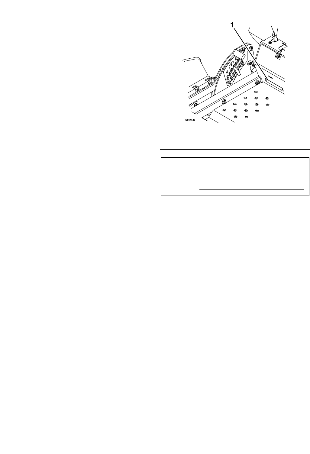
Figure1identiesthelocationofthemodelandserial
numbersontheproduct.Writethenumbersinthe
spaceprovided.
Figure1
1.Modelandserialnumberlocation
ModelNo.
SerialNo.
3

Contents
Introduction...........................................................3
Safety.....................................................................5
SafetyAlertSymbol.........................................5
SafeOperatingPractices..................................5
SafetyandInstructionalDecals......................11
Specications........................................................15
ModelNumbers.............................................15
Systems..........................................................15
Dimensions....................................................17
TorqueRequirements.....................................18
ProductOverview.................................................18
Operation..............................................................19
Controls.........................................................19
Pre-Start.........................................................21
OperatingInstructions...................................22
Transporting..................................................26
Maintenance..........................................................27
RecommendedMaintenanceSchedule(s)............27
PeriodicMaintenance........................................28
CheckEngineOilLevel..................................28
CheckBatteryCharge.....................................28
CheckMowerBlades......................................29
CheckSafetyInterlockSystem........................30
CheckRolloverProtectionsSystems(Roll
Bar)Knobs.................................................31
CheckSeatBelt...............................................31
CheckforLooseHardware.............................31
ServiceAirCleaner.........................................31
ChangeEngineOil.........................................31
CheckHydraulicOilLevel..............................32
CheckTirePressures......................................32
CheckConditionOfBelts...............................32
LubricateGreaseFittings................................32
CheckSparkPlugs..........................................33
ChangeHydraulicSystemFilterand
Fluid..........................................................33
CheckSparkArrester(ifequipped)..................34
ThreadLockingAdhesives..............................35
Copper-BasedAnti-seize...............................35
DielectricGrease............................................35
Adjustments......................................................35
DeckLeveling................................................35
AdjustingtheBladeSlope...............................36
PumpDriveBeltTension................................37
DeckBeltTension..........................................37
AdjustingtheParkingBrake............................37
MotionControlHandleAdjustment...............38
FullForwardTrackingAdjustment..................38
MotionControlLinkageAdjustment..............39
AdjustingtheSeatRideSuspension.................40
ElectricClutchAdjustment.............................40
Cleaning............................................................42
CleanEngineandExhaustSystem
Area...........................................................42
RemoveEngineShroudsandClean
CoolingFins...............................................42
CleanHydroFanCoolingFins........................42
CleanDebrisFromMachine...........................42
CleanGrassBuild-UpUnderDeck.................42
WasteDisposal...............................................42
Troubleshooting....................................................44
Schematics............................................................46
4

Safety
Safety
SafetyAlertSymbol
ThislawnmowermeetsorexceedstheB71.4
specicationsoftheAmericanNationalStandards
Instituteineffectatthetimeofproduction.
Exmarkdesignedandtestedthislawnmowertooffer
reasonablysafeservice;however,failuretocomply
withthefollowinginstructionsmayresultinpersonal
injury.
ThisSafetyAlertSymbol(Figure2)isusedbothin
thismanualandonthemachinetoidentifyimportant
safetymessageswhichmustbefollowedtoavoid
accidents.
Thissymbolmeans:ATTENTION!BECOME
ALERT!YOURSAFETYISINVOLVED!
Figure2
SafetyAlertSymbol
Thesafetyalertsymbolappearsaboveinformation
whichalertsyoutounsafeactionsorsituations
andwillbefollowedbythewordDANGER,
WARNING,orCAUTION.
DANGER:Whitelettering/Redbackground.
Indicatesanimminentlyhazardoussituationwhich,if
notavoided,Willresultindeathorseriousinjury.
WARNING:Blacklettering/Orangebackground.
Indicatesapotentiallyhazardoussituationwhich,if
notavoided,Couldresultindeathorseriousinjury.
CAUTION:Blacklettering/Yellowbackground.
Indicatesapotentiallyhazardoussituationwhich,if
notavoided,Mayresultinminorormoderateinjury.
Thismanualusestwootherwordstohighlight
information.Importantcallsattentiontospecial
mechanicalinformationandNoteemphasizes
generalinformationworthyofspecialattention.
SafeOperatingPractices
Training
•ReadtheOperator’sManualandothertraining
material.Iftheoperator(s)ormechanic(s)can
notreadEnglishitistheowner’sresponsibilityto
explainthismaterialtothem.
•Becomefamiliarwiththesafeoperationofthe
equipment,operatorcontrols,andsafetysigns.
•Alloperatorsandmechanicsshouldbetrained.
Theownerisresponsiblefortrainingtheusers.
•Neverletchildrenoruntrainedpeopleoperate
orservicetheequipment.Localregulationsmay
restricttheageoftheoperator.
•Onlyadultsandmatureteenagersshouldoperate
amower,andevenmatureteenagersshouldhave
adultsupervision.Besureateenager:
1.hasreadandunderstandstheOperator's
Manualandrecognizestherisksinvolved;
2.issufcientlymaturetousecaution;and
3.isofsufcientsizeandweighttooperate
thecontrolscomfortablyandtomanagethe
mowerwithouttakingrisks.
•Theowner/usercanpreventandisresponsible
foraccidentsorinjuriesoccurringtohimselfor
herself,otherpeopleorproperty.
Preparation
•Evaluatetheterraintodeterminewhataccessories
andattachmentsareneededtoproperlyand
safelyperformthejob.Onlyuseaccessoriesand
attachmentsapprovedbyExmark.
•Wearappropriateclothingincludingsafetyglasses,
substantialfootwear,longtrousers,andhearing
protection.DoNotoperatewhenbarefootor
whenwearingopensandals.Longhair,loose
clothingorjewelrymaygettangledinmoving
parts.
CAUTION
Thismachineproducessoundlevelsinexcess
of85dBAattheoperator’searandcancause
hearinglossthroughextendedperiodsof
exposure.
Wearhearingprotectionwhenoperatingthis
machine.
5

Safety
•Inspecttheareawheretheequipmentistobe
usedandremoveallrocks,toys,sticks,wires,
bones,andotherforeignobjectswhichcanbe
thrownbythemachineandmaycausepersonal
injurytotheoperatororbystanders.
DANGER
Incertainconditionsgasolineisextremely
ammableandvaporsareexplosive.
Areorexplosionfromgasolinecanburn
you,others,andcausepropertydamage.
•Fillthefueltankoutdoorsonlevelground,
inanopenarea,whentheengineiscold.
Wipeupanygasolinethatspills.
•Neverrellthefueltankordrainthe
machineindoorsorinsideanenclosed
trailer.
•DoNotllthefueltankcompletelyfull.
Fillthefueltanktothebottomoftheller
neck.Theemptyspaceinthetankallows
gasolinetoexpand.Overllingmayresult
infuelleakageordamagetotheengine
oremissionsystem.
•Neversmokewhenhandlinggasoline,and
stayawayfromanopenameorwhere
gasolinefumesmaybeignitedbyspark.
•Storegasolineinanapprovedcontainer
andkeepitoutofthereachofchildren.
•Addfuelbeforestartingtheengine.Never
removethecapofthefueltankoradd
fuelwhenengineisrunningorwhenthe
engineishot.
•Iffuelisspilled,DoNotattempttostart
theengine.Moveawayfromtheareaof
thespillandavoidcreatinganysourceof
ignitionuntilfuelvaporshavedissipated.
•DoNotoperatewithoutentireexhaust
systeminplaceandinproperworking
condition.
DANGER
Incertainconditionsduringfueling,static
electricitycanbereleasedcausingaspark
whichcanignitegasolinevapors.Areor
explosionfromgasolinecanburnyouand
othersandcausepropertydamage.
•Alwaysplacegasolinecontainersonthe
groundawayfromyourvehiclebefore
lling.
•DoNotllgasolinecontainersinsidea
vehicleoronatruckortrailerbedbecause
interiorcarpetsorplastictruckbedliners
mayinsulatethecontainerandslowthe
lossofanystaticcharge.
•Whenpractical,removegas-powered
equipmentfromthetruckortrailerand
refueltheequipmentwithitswheelson
theground.
•Ifthisisnotpossible,thenrefuelsuch
equipmentonatruckortrailerfroma
portablecontainer,ratherthanfroma
gasolinedispensernozzle.
•Ifagasolinedispensernozzlemustbe
used,keepthenozzleincontactwiththe
rimofthefueltankorcontaineropening
atalltimesuntilfuelingiscomplete.
WARNING
Gasolineisharmfulorfatalifswallowed.
Long-termexposuretovaporshascaused
cancerinlaboratoryanimals.Failuretouse
cautionmaycauseseriousinjuryorillness.
•Avoidprolongedbreathingofvapors.
•Keepfaceawayfromnozzleandgas
tank/containeropening.
•Keepawayfromeyesandskin.
•Neversiphonbymouth.
•Checkthattheoperator'spresencecontrols,
safetyswitches,andshieldsareattachedand
functioningproperly.DoNotoperateunlessthey
arefunctioningproperly.
6

Safety
Operation
WARNING
Operatingengineparts,especiallythemufer,
becomeextremelyhot.Severeburnscanoccur
oncontactanddebris,suchasleaves,grass,
brush,etc.cancatchre.
•Allowengineparts,especiallythemufer,to
coolbeforetouching.
•Removeaccumulateddebrisfrommuferand
enginearea.
•Installandmaintaininworkingordera
sparkarresterbeforeusingequipment
onforest-covered,grass-covered,or
brush-coveredunimprovedland.
WARNING
Engineexhaustcontainscarbonmonoxide,
whichisanodorlessdeadlypoisonthatcankill
you.
DoNotrunengineindoorsorinasmallconned
areawheredangerouscarbonmonoxidefumes
cancollect.
•Operateonlyindaylightorgoodarticiallight,
keepingawayfromholesandhiddenhazards.
•Besurealldrivesareinneutralandparkingbrake
isengagedbeforestartingengine.Useseatbelts
withtherollbarintheraisedandlockedposition.
•Neveroperatethemowerwithdamagedguards,
shields,orcovers.Alwayshavesafetyshields,
guards,switchesandotherdevicesinplaceandin
properworkingcondition.
•Nevermowwiththedischargedeectorraised,
removedoralteredunlessthereisagrass
collectionsystemormulchkitinplaceand
workingproperly.
•DoNotchangetheenginegovernorsettingor
overspeedtheengine.
•Parkmachineonlevelground.Stopengine,wait
forallmovingpartstostop,removekeyand
engageparkingbrake:
–Beforechecking,cleaningorworkingonthe
mower.
–Afterstrikingaforeignobjectorabnormal
vibrationoccurs(inspectthemowerfor
damageandmakerepairsbeforerestarting
andoperatingthemower).
–Beforeclearingblockages.
–Wheneveryouleavethemower.
•Stopengine,waitforallmovingpartstostop,and
engageparkingbrake:
–Beforerefueling.
–Beforedumpingthegrasscatcher.
WARNING
Hands,feet,hair,clothing,oraccessoriescan
becomeentangledinrotatingparts.Contact
withtherotatingpartscancausetraumatic
amputationorseverelacerations.
•DoNotoperatethemachinewithout
guards,shields,andsafetydevicesinplace
andworkingproperly.
•Keephands,feet,hair,jewelry,orclothing
awayfromrotatingparts.
•NEVERcarrypassengers.DONOToperate
themowerwhenpeople,especiallychildren,or
petsareinthearea.
•Bealert,slowdownandusecautionwhen
makingturns.Lookbehindandtothesidebefore
changingdirections.
•Stoptheblades,slowdown,andusecaution
whencrossingsurfacesotherthangrassandwhen
transportingthemowertoandfromtheareato
bemowed.
•Beawareofthemowerdischargepathanddirect
dischargeawayfromothers.
•DoNotoperatethemowerundertheinuence
ofalcoholordrugs.
•Useextremecarewhenloadingorunloadingthe
machineintoatrailerortruck.
•Usecarewhenapproachingblindcorners,shrubs,
trees,orotherobjectsthatmayobscurevision.
SlopeOperation
UseExtremecautionwhenmowingand/orturning
onslopesaslossoftractionand/ortip-overcould
occur.Theoperatorisresponsibleforsafeoperation
onslopes.
7
Safety
DANGER
Operatingonwetgrassorsteepslopescancause
slidingandlossofcontrol.Wheelsdroppingover
edges,ditches,steepbanks,orwatercancause
rollovers,whichmayresultinseriousinjury,
deathordrowning.
•DoNotmowslopeswhengrassiswet.
•DoNotmowneardrop-offsornearwater.
•DoNotmowslopesgreaterthan15degrees.
•Reducespeedanduseextremecautionon
slopes.
•Avoidsuddenturnsorrapidspeedchanges.
•Keeptherollbarintheraisedandlocked
positionanduseseatbelt.
•Seeinsidethebackcovertodeterminethe
approximateslopeangleoftheareatobemowed.
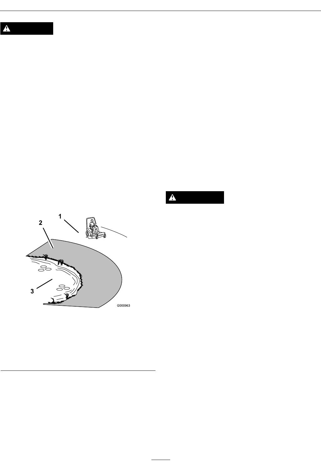
•Useawalkbehindmowerand/orahandtrimmer
neardrop-offs,ditches,steepbanksorwater.
(Figure3).
Figure3
1.SafeZone-Usethemowerhereonslopeslessthan15
degrees
2.DangerZone-Useawalkbehindmowerand/orhand
trimmeronslopesgreaterthan15degrees,near
drop-offsandwater.
3.Water
•Removeormarkobstaclessuchasrocks,tree
limbs,etc.fromthemowingarea.Tallgrasscan
hideobstacles.
•Watchforditches,holes,rocks,dipsandrisesthat
changetheoperatingangle,asroughterraincould
overturnthemachine.
•Avoidsuddenstartswhenmowinguphillbecause
themowermaytipbackwards.
•Beawarethatoperatingonwetgrass,acrosssteep
slopesordownhillmaycausethemowertolose
traction.Lossoftractiontothedrivewheelsmay
resultinslidingandalossofbrakingandsteering.
•Alwaysavoidsuddenstartingorstoppingona
slope.Iftireslosetraction,disengagetheblades
andproceedslowlyofftheslope.
•Followthemanufacturer’srecommendationsfor
wheelweightsorcounterweightstoimprove
stability.
•Useextremecarewithgrasscatchersor
attachments.Thesecanchangethestabilityofthe
machineandcauselossofcontrol.
UsingtheRolloverProtectionSystem
(ROPS)
ARolloverProtectionSystem(rollbar)isinstalled
ontheunit.
WARNING
Thereisnorolloverprotectionwhentherollbar
isdown.Wheelsdroppingoveredges,ditches,
steepbanks,orwatercancauserollovers,which
mayresultinseriousinjury,deathordrowning.
•Keeptherollbarintheraisedandlocked
positionanduseseatbelt.
•Lowertherollbaronlywhenabsolutely
necessary.
•DoNotwearseatbeltwhentherollbaris
down.
•Driveslowlyandcarefully.
•Raisetherollbarassoonasclearance
permits.
•Checkcarefullyforoverheadclearances(i.e.
branches,doorways,andelectricalwires)before
drivingunderanyobjectsandDoNotcontact
them.
•Intheeventofarollover,taketheunittoan
AuthorizedServiceDealertohavetheROPS
inspected.
MaintenanceandStorage
•Disengagedrives,lowerimplement,setparking
brake,stopengineandremovekeyordisconnect
sparkplugwire.Waitforallmovementtostop
beforeadjusting,cleaningorrepairing.
8

Safety
•Keepengineandengineareafreefrom
accumulationofgrass,leaves,excessivegrease
oroil,andotherdebriswhichcanaccumulate
intheseareas.Thesematerialscanbecome
combustibleandmayresultinare.
•LetenginecoolbeforestoringandDoNotstore
nearameoranyenclosedareawhereopenpilot
lightsorheatappliancesarepresent.
•Shutofffuelwhilestoringortransporting.Do
Notstorefuelnearamesordrainindoors.
•Parkmachineonlevelground.Neverallow
untrainedpersonneltoservicemachine.
•Usejackstandstosupportcomponentswhen
required.
•Carefullyreleasepressurefromcomponentswith
storedenergy.
•Disconnectbatteryorremovesparkplugwire
beforemakinganyrepairs.Disconnectthe
negativeterminalrstandthepositivelast.
Reconnectpositiverstandnegativelast.
•Usecarewhencheckingblades.Wraptheblade(s)
orweargloves,andusecautionwhenservicing
them.Onlyreplacedamagedblades.Never
straightenorweldthem.
•Keephandsandfeetawayfrommovingparts.
Ifpossible,DoNotmakeadjustmentswiththe
enginerunning.
•Chargebatteriesinanopenwellventilatedarea,
awayfromsparkandames.Unplugcharger
beforeconnectingordisconnectingfrombattery.
Wearprotectiveclothinganduseinsulatedtools.
DANGER
Chargingorjumpstartingthebatterymay
produceexplosivegases.Batterygasescan
explodecausingseriousinjury.
•Keepsparks,ames,orcigarettesaway
frombattery.
•Ventilatewhenchargingorusingbattery
inanenclosedspace.
•Makesureventingpathofbatteryis
alwaysopenoncebatteryislledwith
acid.
•Alwaysshieldeyesandfacefrombattery.
DANGER
Batteryelectrolytecontainssulfuricacid,
whichispoisonousandcancausesevere
burns.Swallowingelectrolytecanbefatalor
ifittouchesskincancausesevereburns.
•Wearsafetyglassestoshieldeyes,and
rubberglovestoprotectskinandclothing
whenhandlingelectrolyte.
•DoNotswallowelectrolyte.
•Intheeventofanaccident,ushwith
waterandcalladoctorimmediately.
CAUTION
Iftheignitionisinthe“ON”positionthere
ispotentialforsparksandengagementof
components.Sparkscouldcauseanexplosion
ormovingpartscouldaccidentallyengage
causingpersonalinjury.
Besureignitionswitchisinthe“OFF”
positionbeforechargingthebattery.
•Keepallguards,shieldsandallsafetydevicesin
placeandinsafeworkingcondition.
•Checkallboltsfrequentlytomaintainproper
tightness.
•Frequentlycheckforwornordeteriorating
componentsthatcouldcreateahazard.
WARNING
Removingstandardoriginalequipmentparts
andaccessoriesmayalterthewarranty,traction,
andsafetyofthemachine.Failuretouseoriginal
Exmarkpartscouldcauseseriousinjuryor
death.Makingunauthorizedchangestothe
engine,fuelorventingsystem,mayviolateEPA
andCARBregulations.
Replaceallpartsincluding,butnotlimitedto,
tires,belts,blades,andfuelsystemcomponents
withoriginalExmarkparts.
9

Safety
WARNING
Hydraulicuidescapingunderpressure
canpenetrateskinandcauseinjury.Fluid
accidentallyinjectedintotheskinmustbe
surgicallyremovedwithinafewhoursbyadoctor
familiarwiththisformofinjuryorgangrenemay
result.
•Ifequipped,makesureallhydraulicuid
hosesandlinesareingoodconditionandall
hydraulicconnectionsandttingsaretight
beforeapplyingpressuretohydraulicsystem.
•Keepbodyandhandsawayfrompinhole
leaksornozzlesthatejecthighpressure
hydraulicuid.
•Usecardboardorpaper,notyourhands,to
ndhydraulicleaks.
•Safelyrelieveallpressureinthehydraulic
systembyplacingthemotioncontrollevers
inneutralandshuttingofftheenginebefore
performinganyworkonthehydraulicsystem.
10
Safety
SafetyandInstructionalDecals
•Keepallsafetysignslegible.Removeallgrease,
dirtanddebrisfromsafetysignsandinstructional
labels.
•Replaceallworn,damaged,ormissingsafety
signs.
•Whenreplacementcomponentsareinstalled,be
surethatcurrentsafetysignsareafxedtothe
replacedcomponents.
•Ifanattachmentoraccessoryhasbeeninstalled,
makesurecurrentsafetysignsarevisible.
•Newsafetysignsmaybeobtainedfrom
yourauthorizedExmarkequipmentdealeror
distributororfromExmarkMfg.Co.Inc.
•Safetysignsmaybeafxedbypeelingoffthe
backingtoexposetheadhesivesurface.Apply
onlytoaclean,drysurface.Smoothtoremove
anyairbubbles.
•Familiarizeyourselfwiththefollowingsafetysigns
andinstructionlabels.Theyarecriticaltothesafe
operationofyourExmarkcommercialmower.
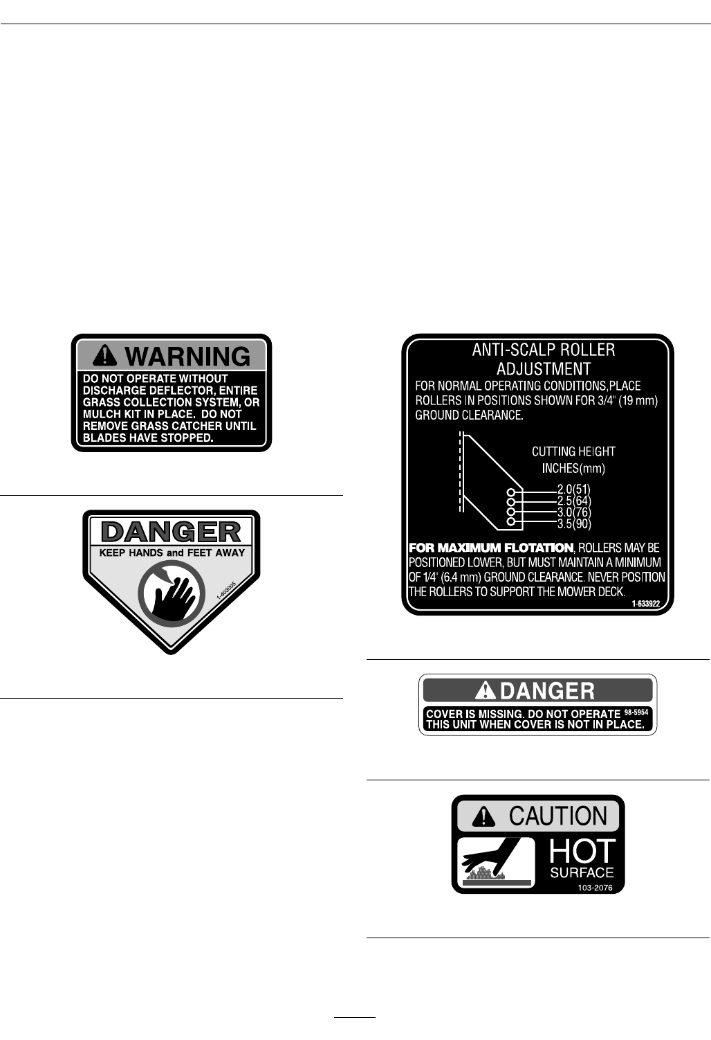
1-303508
1-403005
1-633922
98-5954
103-2076
11

Safety
107-2102
109-3148
109-6014
116-1119
116-1496
116-3303
12
Safety
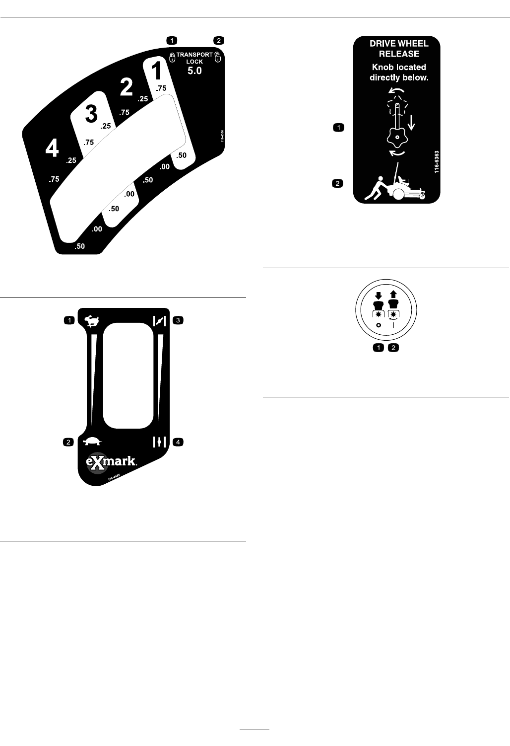
116-4308
1.Latch2.Unlatch
116-4465
1.Fast3.Choke-on
2.Slow4.Choke-off
116-6363
1.Rotatethedriverelease
knobtoloosen,slidethe
knob,andtighten.
2.Pushthemachine.
PTOSwitchSymbols
1.PTO–disengage2.PTO–engage
13
Safety
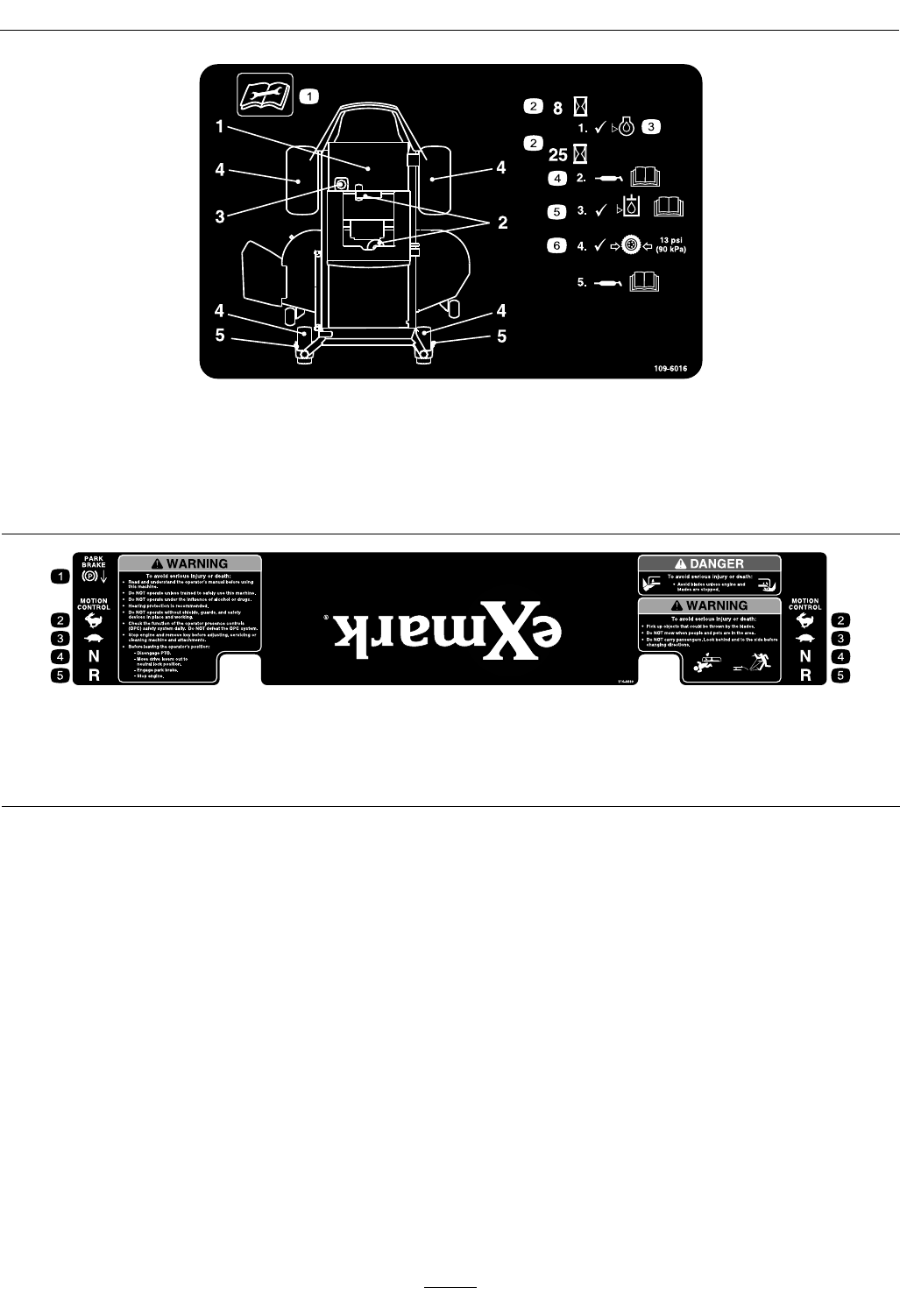
109-6016
1.Readtheinstructionsbeforeservicingorperforming
maintenance
4.RefertotheOperator'smanualforgreaseinstructions
2.Timeinterval5.CheckhydraulicoillevelandrefertotheOperator's
manualorfurtherinstructions
3.Checkoillevel6.Checktirepressure
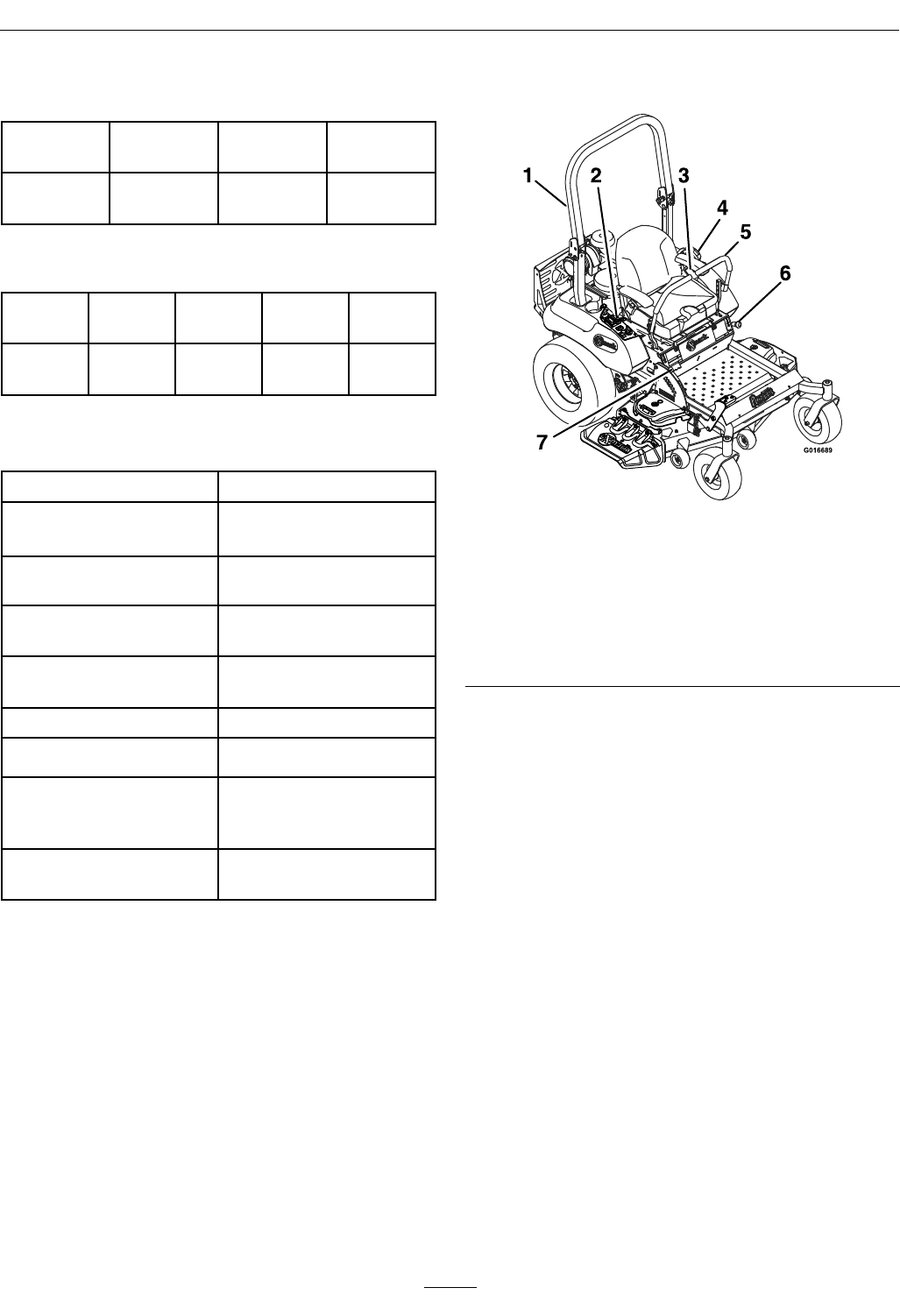
116-4430
1.Parkbrake—engage4.Neutral
2.Fast5.Reverse
3.Slow
14

Specications
Specications
ModelNumbers
SerialNos:312,000,000andHigher
PNS600KA443;PNS651KA483;PNS680KC523;PNS740KC604
Systems
Engine
•EngineSpecications:SeeyourEngineOwner’s
Manual
•EngineOilType:Exmark4–CyclePremium
EngineOil
•RPM:FullSpeed:
Kawasaki:3750±50RPM(PTOnotengaged)
Idle:1500±100RPM
Kohler:3700±50RPM(PTOnotengaged)Idle:
1500±100RPM
FuelSystem
•Capacity:7.0gal.(26.5L)
•FuelRecommendations:
–Forbestresults,useonlyclean,fresh,unleaded
gasolinewithanoctaneratingof87orhigher
((R+M)/2ratingmethod).
–Oxygenatedfuelwithupto10%ethanolor
15%MTBEbyvolumeisacceptable.
–DoNotuseethanolblendsofgasoline(such
asE15orE85)withmorethan10%ethanol
byvolume.Performanceproblemsand/or
enginedamagemayresultwhichmaynotbe
coveredunderwarranty.
–DoNotusegasolinecontainingmethanol.
–DoNotstorefueleitherinthefueltankor
fuelcontainersoverthewinterunlessafuel
stabilizerisused.
–DoNotaddoiltogasoline.
•FuelFilter:
Kohler:KohlerP/N2405013
Kawasaki:KawasakiP/N49019-7005
•FuelShut-OffValve:
AllUnits:1/4turnincrements(“ON”,“OFF”).
ElectricalSystem
•ChargingSystem:FlywheelAlternator
•ChargingCapacity:15amps
•BatteryType:BCIGroupU1
•RecommendedMinimumBatteryCCA:260CCA
•BatteryVoltage:12Volt
•Polarity:NegativeGround
•Fuses:
Allunits:
–25ampmainfuse
–20ampchargingsystemfuse
–10ampPTOfuse
–15ampaccessoryfuse
SafetyInterlockSystem
•LCDindicatorsappearforthePTO,parkbrake,
drivelevers,andoperatorpresenceinthemessage
displayontheRHcontrolpanel.
•PTOmustbedisengaged,brakeengaged,and
motioncontrolleversout(neutrallock)tostart
engine.(Itisnotnecessaryfortheoperatortobe
intheseattostarttheengine.)
•OperatormustbeinseatwhenPTOisengaged,
brakeisdisengaged,ormotioncontrolleversare
movedinorenginewillstop.
•Enginewillstopifeithertheleft,theright,or
bothleversaremovedfromneutrallockposition
whilebrakeisengaged.
OperatorControls
•SteeringandMotionControl:
Note:Motioncontrolleversareadjustableto
threeheights.
–Separatelevers,oneachsideoftheconsole,
controlspeedanddirectionoftravelofthe
respectivedrivewheels.
15

Specications
–Steeringiscontrolledbyvaryingtheposition
oftheleversrelativetoeachother.
–Movingmotioncontrolleversoutward(in
slots)locksthedrivesysteminneutral.
•PTOEngagementSwitch:Engageselectricclutch
(todrivebelt)whichengagesmowerblades.
•ParkingBrakeLever:Engagesparkingbrake.
•DeckHeightAdjustmentLever:Setscutting
heighttodesiredposition.
•DeckLiftPedal:Footpedalthatliftsdeck.
•TransportLock:Latchingposition:Automatically
latchesatthetransportposition.
Seat
•Type:Standardseatwithfoampaddedseat
cushionwitharmrestsandintegralsafetyswitch.
Optionalseat:Seatwithhighback,extra
widefoampaddedseatcushionwithinternal
suspension,thickbolstering,two-tonecover,
armrests,integralsafetyswitch,andseatvibration
isolationsystem.
Optionalseataccessoriesforunitswithstandard
seats:
–Customridesuspensionsystemtoenhance
StandardSeat.Addsapproximately3inches
(7.6cm)toseatheight.
–Deluxesuspensionseatwithhighback,
(dampened,adjustablespringsuspension),
armrests,andintegralsafetyswitch.Adds
approximately1/2inch(1.3cm)toseatheight.
•Mounting:Adjustableforeandaftonseattracks.
•Armrests:Moldedip-uparmrests.
•SeatSafetySwitch:
Integratedseatswitch.Timedelayseatswitch
eliminatesroughgroundcut-outs.
HydrostaticGroundDriveSystem
•Twounitizedhydrostatictransmissions:
–Unitswith44,48,or52inchdecks:
HydroGearZT3100
–Unitswith60inchdeck:
HydroGearZT3400
•HydraulicOilType:ExmarkPremiumHydroOil.
•HydraulicOilCapacity:77oz(2.3L)perside
•HydraulicFilter:P/N109-3321
•Speeds:
–Forward:
◊Unitswith44,48,or52inchdecks:
0-8mph(12.9km/hr)forward.
◊Unitswith60inchdeck:
0-9mph(14.5km/hr)forward.
–Reverse:
◊Unitswith44,48,or52inchdecks:
0-5mph(8.0km/hr)reverse.
◊Unitswith60inchdeck:
0-6mph(9.7km/hr)reverse.
•Drivewheelreleasevalvesallowmachinetobe
movedwhenengineisnotrunning.
Tires&Wheels
Drive
Pneumatic(Airlled)
DeckSize44,48,&5260
Quantity22
TreadTurfMasterK500SuperTurf
Size22x9.50-1223x10.50-12
PlyRating44
Pressure13psi(90kPa)13psi(90kPa)
FrontCaster
Pneumatic(Airlled)
DeckSizeAllUnits
Quantity2
TreadSmooth
Size13x5.00-6
PlyRating4
Pressure13psi(90kPa)
CuttingDeck
•CuttingWidth:
–44inchDeck:(111.8cm)
–48inchDeck:(121.9cm)
–52inchDeck:(132.1cm)
–60inchDeck:(152.4cm)
•Discharge:Side
•BladeSize:
16

Specications
–44inchDeck:22.25inches(56.5cm)–(2ea.)
–48inchDeck:16.25inches(41.3cm)–(3ea.)
–52inchDeck:18.00inches(45.7cm)–(3ea.)
–60inchDeck:20.50inches(52.1cm)–(3ea.)
•BladeSpindles:Solidsteelspindleswith.98inch
(25mm)I.D.bearings.
•DeckDrive:“B”Sectionbeltwithself-tensioning
idler.
•Electricclutch:
–44,48,&52inchdecks:175ft-lbMagStop
–60inchdeck:200ft-lbMagStopw/spotbrake
•Deck:Fulloatingdeckisattachedtoout-front
supportframe.Anti-scalprollersprovide
maximumturfprotection.Deckdesignallowsfor
bagging,mulchingorsidedischarge.
–44inchDeck:2anti-scalprollers
–48inchDeck:3anti-scalprollers
–52inchDeck:3anti-scalprollers
–60inchDeck:4anti-scalprollers
•DeckDepth:
–44inchDeck:5.0inches(12.7cm)
–48inchDeck:5.0inches(12.7cm)
–52inchDeck:5.0inches(12.7cm)
–60inchDeck:5.5inches(14.0cm)
•CuttingHeightAdjustment:
Footactivatedleverisusedtoadjustthecutting
heightfrom11/2inch(3.8cm)to5inches(12.7
cm)in1/4inch(6.4mm)increments.
•MulchingKit:Optional.
Dimensions
OverallWidth:
44inchDeck48inchDeck
WithoutDeck45.8inches
(116.3cm)
45.8inches
(116.3cm)
DeectorUp48.2inches
(122.4cm)
50.7inches
(128.8cm)
DeectorDown56.4inches
(143.3cm)
59.5inches
(151.1cm)
52inchDeck60inchDeck
WithoutDeck45.8inches
(116.3cm)
50.4inches
(128.0cm)
DeectorUp54.2inches
(137.7cm)
61.4inches
(156.0cm)
DeectorDown64.3inches
(163.3cm)
72.8inches
(185.0cm)
OverallLength:
44inchDeck48inchDeck
RollBar-Up78.8inches
(200.2cm)
77.8inches
(197.6cm)
RollBar-Down79.6inches
(202.2cm)
78.6inches
(199.6cm)
52inchDeck60inchDeck
RollBar-Up77.8inches
(197.6cm)
78.8inches
(200.2cm)
RollBar-Down78.6inches
(199.6cm)
79.9inches
(202.9cm)
OverallHeight:
RollBar-UpRollBar-Down
71.3inches(181.1cm)48inches(121.9cm)
TreadWidth:(CentertoCenterof
Tires,Widthwise)
44inchDeck48inchDeck
DriveWheels36.8inches
(93.5cm)
36.8inches
(93.5cm)
CasterWheels26.8inches
(68.1cm)
33.5inches
(85.1cm)
52inchDeck60inchDeck
DriveWheels36.8inches
(93.5cm)
39.7inches
(100.8cm)
CasterWheels33.5inches
(85.1cm)
38.3inches
(97.3cm)
17
ProductOverview
WheelBase:(CenterofCasterTireto
CenterofDriveTire)
44inch
Deck
48inch
Deck
52inch
Deck
60inch
Deck
49.7inches
(126.2cm)
48.7inches
(123.7cm)
48.7inches
(123.7cm)
49.7inches
(126.2cm)
CurbWeight:
44inch
Deck
48inch
Deck
52inch
Deck
60inch
Deck
Kawasaki
Units
822lb
(373kg)
862lb
(391kg)
873lb
(396kg)
948lb
(430kg)
TorqueRequirements
BoltLocationTorque
BladeDriveSheave
MountingNut
130-160ft-lb(176-217
N-m)
BladeMountingBolt
(lubricatewithanti-seize)
50-60ft-lb(68-81N-m)
Anti-ScalpRollerNyloc
NutSeeFigure18
27-33ft-lb(37-45N-m)
Anti-ScalpRollerWhizlock
NutSeeFigure18
27-33ft-lb(37-45N-m)
EngineMountingBolts27-33ft-lb(37-45N-m)
WheelLugNuts70-90ft-lb(95-122N-m)
RolloverProtection
System(RollBar)1/2
inchMountingBolts
77-95ft-lb(104-129N-m)
ClutchRetainingBolt
(securedwiththreadlocker)
49-61ft-lb(66-83N-m)
ProductOverview
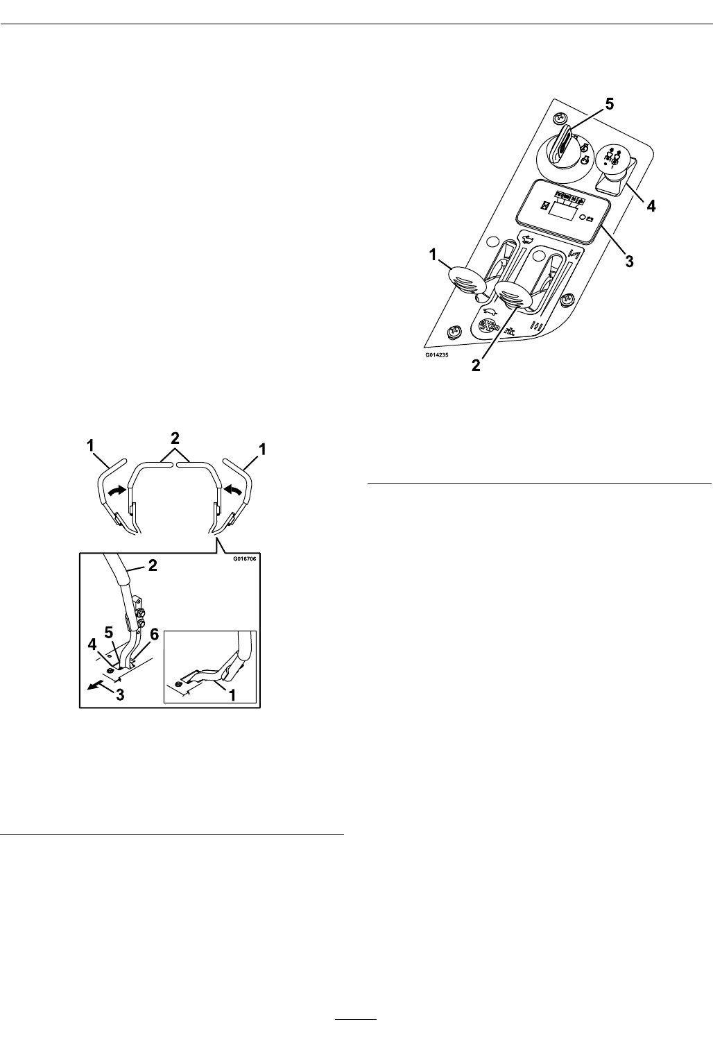
Figure4
1.RolloverProtection
System(ROPS)
5.Motioncontrollevers
2.EngineControls(right
console)
6.Parkingbrake
3.Seatbelt7.Heightofcutadjustment
4.Fuelcap
18
Operation
Operation
Note:Determinetheleftandrightsidesofthe
machinefromthenormaloperatingposition.
Controls
MotionControlLevers
Themotioncontrolleverslocatedoneachsideof
theconsolecontroltheforwardandreversemotion
ofthemachine.
Movingtheleversforwardorbackwardturns
thewheelonthesamesideforwardorreverse
respectively.Wheelspeedisproportionaltothe
amounttheleverismoved.
Movingtheleversoutwardfromthecenterposition
intotheT-slotlocksthemintheneutralposition
(Figure5).
Figure5
1.Neutrallockposition
(handlesout)
4.Forward
2.Neutraloperateposition
(handlesin)
5.Neutral(operate)
3.Frontofunit6.Reverse
ChokeControl
Locatedonrightconsole(blacklever)(seeFigure6).
Thechokeisusedtoaidinstartingacoldengine.
Movingthechokeleverforwardwillputthechokein
the“ON”positionandmovingthechokelevertothe
rear,tothedetent,willputthechokeinthe“OFF”
position.DoNotrunawarmenginewithchokein
the“ON”position.
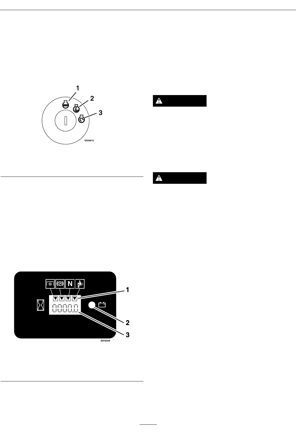
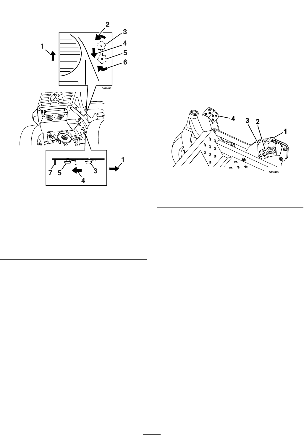
Figure6
1.Throttlelever4.Bladecontrolswitch
(powertake-off)
2.Chokelever5.Ignitionswitch
3.Hourmeter
ThrottleControl
Locatedonrightconsole(redlever)(seeFigure6).
Thethrottleisusedtocontrolenginespeed.Moving
thethrottleleverforwardwillincreaseenginespeed
andmovingthethrottlelevertotherearwilldecrease
enginespeed.Movingthethrottleforwardintothe
detentisfullthrottle.
BrakeLever
Locatedonleftsideofunit,justtothefrontofthe
LHmotioncontrollever.
Thebrakeleverengagesaparkingbrakeonthedrive
wheels.
Pulltheleverupandrearwardtoengagethebrake.
Pushtheleverforwardanddowntodisengagethe
brake.
Theunitmustbetieddownandbrakeengagedwhen
transporting.
IgnitionSwitch
Locatedonrightconsole(seeFigure6).
19
Operation
Theignitionswitchisusedtostartandstopthe
engine.Theswitchhasthreepositions“OFF”,“ON”
and“START”.Insertkeyintoswitchandrotate
clockwisetothe“ON”position.Rotateclockwiseto
thenextpositiontoengagethestarter(keymustbe
heldagainstspringpressureinthisposition).Allow
thekeytoreturntothe“on”positionimmediately
aftertheenginestarts.
Figure7
1.Off3.Start
2.On
Note:Brakemustbeengaged,motioncontrol
leversout(neutrallockposition)andPTOswitch
disengagedtostartengine.(Itisnotnecessaryforthe
operatortobeintheseattostarttheengine.)
HourMeter
Locatedonthecontrolpanel(seeFigure6and
Figure8).
Thehourmeterrecordsthenumberofhoursthat
theenginehasrun.
Figure8
1.LCDindicators3.Hour/Voltagedisplay
2.Lowvoltageindicator
light
FuelShut-OffValve
LocatedbythelowerLHROPStubemounting.
Thefuelshut-offvalveisusedtoshutoffthefuel
whenthemachinewillnotbeusedforafewdays,
duringtransporttoandfromthejobsite,andwhen
parkedinsideabuilding.
Alignvalvehandlewiththefuellinetoopen.Rotate
90°toclose.
DriveWheelReleaseValves
WARNING
Handsmaybecomeentangledintherotating
drivecomponentsbelowtheenginedeck,which
couldresultinseriousinjuryordeath.
Stopengine,removekey,allowallthemoving
partstostopbeforeaccessingthedrivewheel
releasevalves.
WARNING
Theengineandhydraulicdriveunitscanbecome
veryhot.Touchingahotengineorhydraulic
driveunitscancausesevereburns.
Allowtheengineandhydraulicdriveunitsto
coolcompletelybeforeaccessingthedrivewheel
releasevalves.
Locatedontheleftandrightsidesunderneaththe
enginedeck.
Duringnormaloperatingconditions,thedrivewheel
releasevalvesarepositionedinfrontoftheslots.If
themachinehastobepushedbyhand,thevalves
mustbeinthe“released”position(seeFigure9).
20
Operation
Figure9
1.Frontofthemachine
2.Rotatebypassreleaseknobcounterclockwisetoloosen
3.Leverpositionforoperatingthemachine
4.Pullleverinthisdirectiontopushthemachine
5.Leverpositionforpushingthemachine
6.Rotatebypassreleaseknobclockwisetotighten
7.Releaselever
Toreleasethedrivesystem(seeitem1inFigure9),
loosentheknobbyturningcounterclockwise.Then
pullthereleaseleverontheundersideofmachine
towardsthebackofthemachineandretightenthe
knobtoholdthereleaseleverbackinthereleased
state.Repeatthisoneachsideofthemachine.
Releasetheparkingbrake.Themachineisnowable
tobepushedbyhand.
Toresetthedrivesystem(seeitem2inFigure9),
loosentheknobbyturningcounterclockwise.Then
pushthereleaseleverontheundersideofmachine
towardsthefrontofthemachineandretightenthe
knobtoholdthereleaseleverintheoperatingstate.
Repeatthisoneachsideofthemachine.
DoNottowmachine.
PTOEngagementSwitch
Locatedonrightconsole(seeFigure6).
Switchmustbepulledout(up)toengagetheblades.
Switchispushedintodisengagetheblades.
DeckLiftPedal
Locatedattherightfrontcorneroftheoorpan.
Pushthepedalforwardwithyourfoottoraisethe
cuttingdeck.Allowthepedaltomoverearwardto
lowerthecuttingdecktothecutheightthathasbeen
set.
Figure10
1.Transportlockhandle3.Heightofcutdecal
2.Heightadjustmentpin4.Deckfootpedal
TransportLock
Locatedontheheightofcutadjustmentplate(see
Figure10).
Thetransportlatchingmechanismwillautomatically
engagewhenthedeckisraisedtothetransport
position.Toreleasethedeckfromthetransport
position:pushthefootpedaltoremovetheloadfrom
thetransportlatchingmechanism,pullthetransport
lockhandlerearward,andletthepedalcomebackto
lowerthedeckdowntothedesiredcutheight.
Pre-Start
Fillfueltanks.SeeFuelRecommendationsin
theSpecicationssectionforadditionalgasoline
information.
DoNotaddoiltogasoline.
DoNotoverllfueltank.Fillthefueltanktothe
bottomofthellerneck.Theemptyspaceinthe
tankallowsgasolinetoexpand.Overllingmayresult
infuelleakageordamagetotheengineoremission
system.
21
Operation
Makesureyouunderstandthecontrols,their
locations,theirfunctions,andtheirsafety
requirements.
RefertotheMaintenancesectionandperformallthe
necessaryinspectionandmaintenancesteps.
OperatingInstructions
RaisetheRolloverProtectionSystem
(ROPS)
Important:Therollbarisanintegraland
effectivesafetydevice.Keeptherollbarinthe
raisedandlockedpositionwhenoperatingthe
mower.Lowertherollbartemporarilyonlywhen
absolutelynecessary.
1.Theknobmustbecompletelylatchedwiththe
tabsinterlockingasshowninFigure11tolock
therollbarintheraised,operateposition.
2.Applyforwardpressuretotheupperhoopofthe
rollbar.
3.Pulltheknobandrotate90°toholdinthe
unlatchedpositiontolowertherollbar.
4.Toreturntotheoperateposition,raisetheroll
bar,andthenrotateknobs90°sothatthetabs
interlockpartially.Applyforwardpressuretothe
rollbarupperhoopandobservethattheknobs
returntothecompletelylatchedposition.
G014402
1
234
5
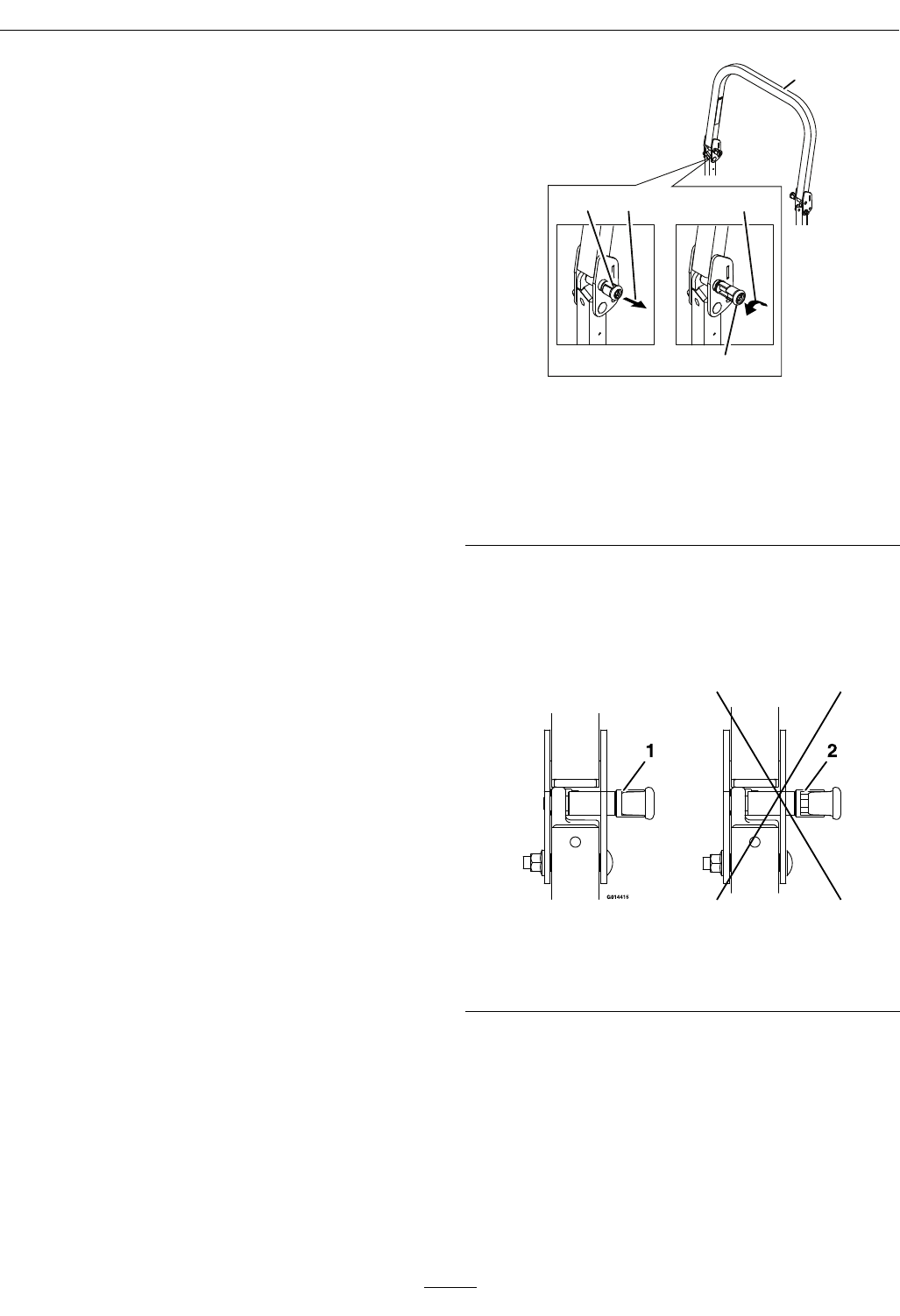
Figure11
1.Rollbarupperhoop
2.Knobin“latched”position
3.Pullknobtounlatch
4.Rotate90°toholdunlatched
5.Knobin“unlatched”position
5.Makesuretheknobsarefullyengagedwiththe
rollbarintheraisedposition.Theupperhoopof
therollbarmayneedtobepushedforwardor
pulledrearwardtogetbothknobsfullyengaged
(seeFigure12).
Figure12
1.Engaged2.Partiallyengaged—Do
NotoperatewithROPS
inthiscondition.
Important:Alwaysusetheseatbeltwiththe
rollbarintheoperate(raised)position.Ensure
thattherearpartoftheseatissecuredwiththe
seatlatch.
OpentheFuelShut-OffValve
Rotatethevalveandalignwiththefuellinetoopen.
22

Operation
StartingtheEngine
1.Movethemotioncontrolleversouttotheneutral
lockposition.
2.Pullupandbackontheparkingbrakeleverto
engagetheparkingbrake.
3.PushdownonthePTOswitchtothe“disengage”
position.
Note:Itisnotnecessaryfortheoperatortobe
intheseattostarttheengine.
4.Placethethrottlemidwaybetweenthe“SLOW”
and“FAST”positions.
5.Onacoldengine,pushthechokeleverforward
intothe“ON”position.
Onawarmengine,leavethechokeinthe“OFF”
position.
6.Turnignitionswitchtothe“START”position.
Releasetheswitchassoonastheenginestarts.
Important:DoNotcranktheengine
continuouslyformorethantensecondsata
time.Iftheenginedoesnotstart,allowa60
secondcool-downperiodbetweenstarting
attempts.Failuretofollowtheseguidelines
canburnoutthestartermotor.
7.Ifthechokeisinthe“ON”position,gradually
returnchoketothe“OFF”positionastheengine
warmsup.
EngagingthePTO
DANGER
Therotatingbladesunderthemowerdeckare
dangerous.Bladecontactcancauseserious
injuryorkillyou.
DoNotputhandsorfeetunderthemoweror
mowerdeckwhenthebladesareengaged.
DANGER
Anuncovereddischargeopeningwillallow
objectstobethrowninanoperator’sor
bystander’sdirection.Also,contactwiththe
bladecouldoccur.Thrownobjectsorblade
contactcancauseseriousinjuryordeath.
Neveroperatethemowerwiththedischarge
deectorraised,removed,oralteredunlessthere
isagrasscollectionsystemormulchkitinplace
andworkingproperly.
ThePTOpush-pullswitchengagesthecuttingblades.
Besurethatallpersonsareclearofthemowerdeck
anddischargeareabeforeengagingPTO.
Important:Operatormustbeinseatbeforethe
PTOcanbeengaged.
1.Setthethrottlemidwaybetweenthe“SLOW”and
“FAST”positions.
2.PullthePTOswitchoutwardtoengagetheblades.
3.Placethethrottleinthe“FAST”positiontobegin
mowing.
DisengagingthePTO
1.Setthethrottlemidwaybetweenthe“SLOW”and
“FAST”positions.
2.PushthePTOswitchintodisengagetheblades.
StoppingtheEngine
1.Bringtheunittoafullstop.
2.Movethemotioncontrolleversouttotheneutral
lockposition.
3.Engagetheparkingbrake.
4.Placethethrottlemidwaybetweenthe“SLOW”
and“FAST”positions.
5.DisengagethePTO.
6.Allowtheenginetorunforaminimumof15
seconds,thenturntheignitionswitchtothe
“OFF”positiontostoptheengine.
7.Removethekeytopreventchildrenorother
unauthorizedpersonsfromstartingengine.
8.Closethefuelshut-offvalvewhenthemachine
willnotbeinuseforafewdays,when
transporting,orwhentheunitisparkedinside
abuilding.
DrivingtheMachine
CAUTION
Machinecanspinveryrapidlybypositioningone
levertoomuchaheadoftheother.Operatormay
losecontrolofthemachine,whichmaycause
damagetothemachineorinjury.
•Usecautionwhenmakingturns.
•Slowthemachinedownbeforemakingsharp
turns.
23
Operation
Important:Tobeginmovement(forwardor
backward)theoperatormustbeintheseat,the
brakelevermustbedisengaged(pusheddown)
beforethemotioncontrolleverscanbemovedin
ortheenginewillstop.
Whenthemotioncontrolleversarepositionedfully
outward(apart)intheT-slot,thedrivesystemisin
theneutrallockposition(Figure13).
Whenthemotioncontrolleversaremoveddirectly
inward(together)thedrivesystemisintheneutral
operateposition.
Figure13
1.Neutrallockposition
(handlesout)
4.Forward
2.Neutraloperateposition
(handlesin)
5.Neutral(operate)
3.FrontofUnit6.Reverse
DrivingForward
1.Releasetheparkingbrake.
2.Movethemotioncontrolleversinwardtothe
centertotheneutralposition.
3.Tomoveforwardinastraightline,moveboth
leversforwardwithequalpressure.
Figure14
Toturnleftorright,pullthemotioncontrollever
backtowardneutralinthedesiredturndirection.
Themachinewillmovefasterthefartherthe
motioncontrolleversaremovedfromtheneutral
position.
4.Tostop,positionbothmotioncontrolleversin
theneutraloperateposition.
DrivinginReverse
1.Movethemotioncontrolleversinwardtothe
neutraloperateposition.
2.Tomoverearwardinastraightline,moveboth
leversrearwardwithequalpressure.
Figure15
24
Operation
Toturnright,releasepressureontheRHmotion
controlleverandtherearofthemachinewill
movetowardstherearandtotheright.
Toturnleft,releasepressureontheLHmotion
controlleverandtherearofthemachinewill
movetowardstherearandtotheleft.
3.Tostop,positionbothmotioncontrolleversin
theneutraloperateposition.
AdjustingtheCuttingHeight
Thecuttingheightofthemowerdeckisadjusted
from11/2to5inches(3.8cmto12.7cm)in1/4
inch(6.4mm)increments.
1.Stopthemachineandmovethemotioncontrol
leversoutwardtotheneutrallockedposition.
2.DisengagethePTO.
3.Raiseandlockthedecktothe5inch(12.7cm)
transportposition(Figure16).
Thedeckisraisedbypushingthefootoperated
deckliftpedalforward.Thepedalislocatedatthe
frontrightcorneroftheoorpan.
Note:Whenchangingthecuttingheight
positions,alwayscometoacompletestop
anddisengagethePTO.
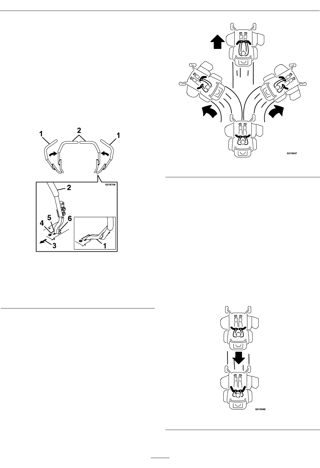
Figure16
1.Transportlockhandle3.Heightofcutdecal
2.Heightadjustmentpin4.Deckfootpedal
4.Inserttheheightadjustmentpinintothehole
correspondingtothedesiredcuttingheight.
Seethedecalonthesideofthedeckliftplatefor
cutheights.
5.Pushthefootleverforward,pullthetransport
lockhandlerearwardandletthedecklower
downtothepredeterminedcutheightbyslowly
decreasingfootpressureallowingthefootlever
totravelrearward.
AdjustingtheAnti-ScalpRollers
Itisrecommendedtochangetheanti-scalproller
position,whentheheightofcuthaschanged.
1.Stopthemachineandmovethemotioncontrol
leversoutwardtotheneutrallockedposition.
2.DisengagethePTO.
3.Engagetheparkbrake.
4.Stoptheengine,removethekeyandwaitforall
movingpartstostop.
5.Afteradjustingtheheightofcut,adjustthe
anti-scalprollersbyremovingthenylocnut,
bushing,springdiscwasherandwhizlocknut.
6.Placetherollersinoneofthepositionsshown
(Figure17).Rollerswillmaintain3/4inch(19
mm)clearancetothegroundtominimizegouging
androllerwearordamage.
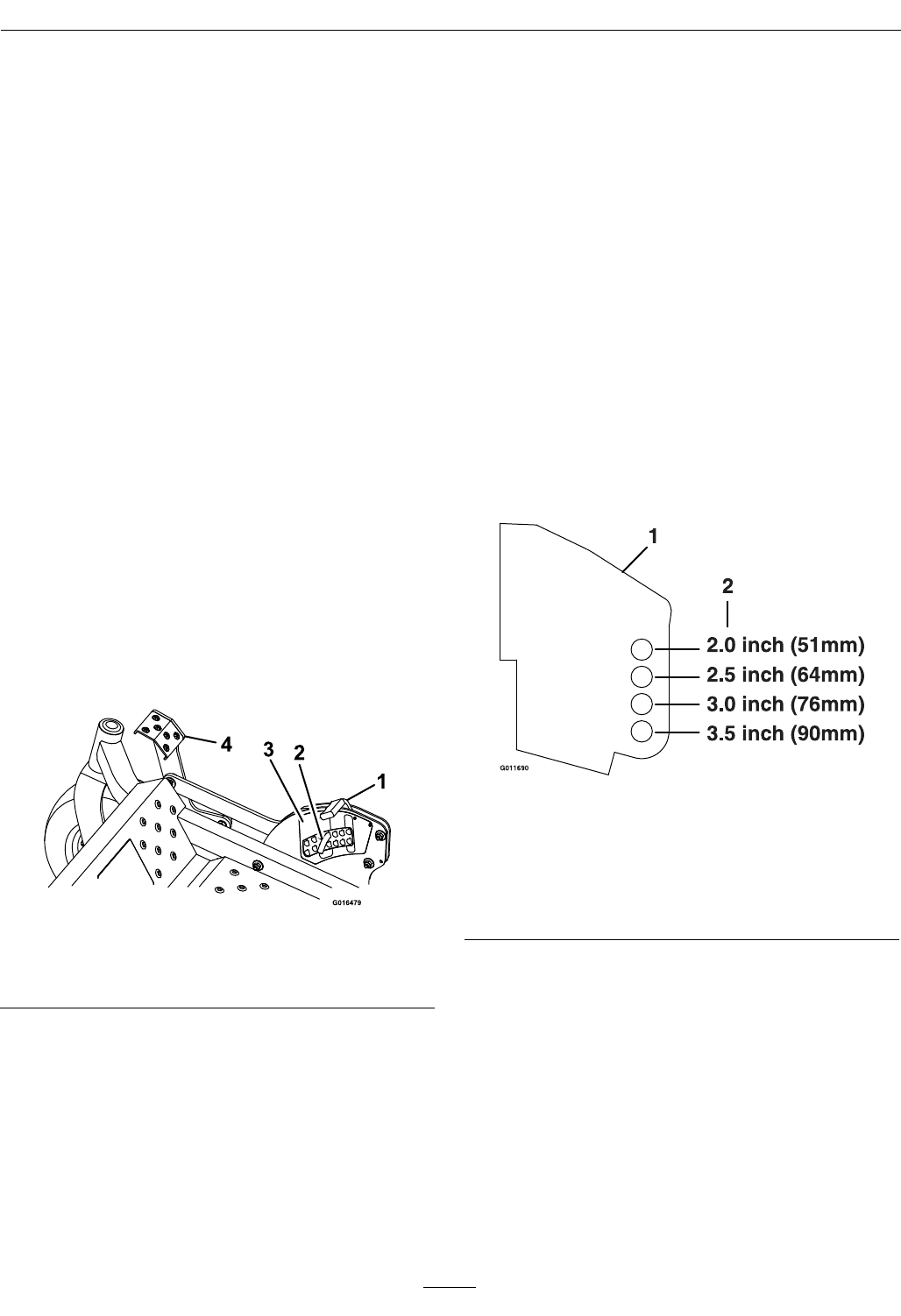
Figure17
Forcuttingheightsabove3.5inches(90mm)usethe
bottomhole.Therollerswillstillbeeffectiveagainst
scalping.
1.Anti-scalproller
mountingbracket
2.Cuttingheight
ForMaximumDeckFlotation,placetherollers
oneholepositionlower.Rollersshouldmaintain
1/4inch(6.4mm)clearancetotheground.Do
Notadjusttherollerstosupportthedeck.
7.Besurethewhizlocknutsareinstalledwiththe
springdiscwasherbetweentheheadofthenut
andthemountingbracket.
Note:Thefootoperateddeckliftassistlever
canbeusedtomomentarilyliftthedecktoclear
objects.BesurethatPTOisdisengaged.
25
Operation
8.Torquethe3/8–16whizlocknutto27-33ft-lb
(37-45N-m)(Figure18).
9.Torquethe3/8nylocnutto27-33ft-lb(37-45
N-m).
Figure18
1.Springdiscwasher
(conetowardsnut)
3.3/8nyloc-torqueto27-33
ft-lb(37-45N-m)
2.Frontrightanti-scalp
bracketshown
4.3/8-16whizlocknut
torqueto27-33ft-lb
(37-45N-m)
Transporting
TransportingaUnit
Useaheavy-dutytrailerortrucktotransportthe
machine.Lockbrakeandblockwheels.Securely
fastenthemachinetothetrailerortruckwithstraps,
chains,cable,orropes.Besurethatthetrailerortruck
hasallnecessarylightingandmarkingasrequiredby
law .Secureatrailerwithasafetychain.
CAUTION
Thisunitdoesnothaveproperturnsignals,
lights,reectivemarkings,oraslowmoving
vehicleemblem.Drivingonastreetorroadway
withoutsuchequipmentisdangerousand
canleadtoaccidentscausingpersonalinjury.
Drivingonastreetorroadwaywithoutsuch
equipmentmayalsobeaviolationofStatelaws
andtheoperatormaybesubjecttotrafctickets
and/ornes.
DoNotdriveaunitonapublicstreetorroadway.
WARNING
Loadingaunitonatrailerortruckincreases
thepossibilityofbackwardtip-over.Backward
tip-overcouldcauseseriousinjuryordeath.
•Useextremecautionwhenoperatingaunit
onaramp.
•Useonlyasingle,fullwidthramp;DoNot
useindividualrampsforeachsideoftheunit.
•Ifindividualrampsmustbeused,useenough
rampstocreateanunbrokenrampsurface
widerthantheunit.
•DoNotexceeda15°anglebetweenrampand
groundorbetweenrampandtrailerortruck.
•Avoidsuddenaccelerationwhiledrivingunit
uparamptoavoidtippingbackward.
•Avoidsuddendecelerationwhilebackingunit
downaramptoavoidtippingbackward.
LoadingaUnit
Useextremecautionwhenloadingunitsontrailersor
trucks.Onefullwidthrampthatiswideenoughto
extendbeyondthereartiresisrecommendedinstead
ofindividualrampsforeachsideoftheunit.The
lowerrearsectionofthetractorframeextendsback
betweentherearwheelsandservesasastopfor
tippingbackward.Havingafullwidthrampprovides
asurfacefortheframememberstocontactifthe
unitstartstotipbackward.Ifitisnotpossibletouse
onefullwidthramp,useenoughindividualrampsto
simulateafullwidthcontinuousramp.
Rampshouldbelongenoughsothattheangles
betweentherampandthegroundandtherampand
thetrailerortruckDoNotexceed15°.Asteeper
anglemaycausemowerdeckcomponentstoget
caughtastheunitmovesfromramptotraileror
truck.Steeperanglesmayalsocausetheunittotip
backward.Ifloadingonornearaslope,position
thetrailerortrucksoitisonthedownsideofthe
slopeandtherampextendsuptheslope.Thiswill
minimizetherampangle.Thetrailerortruckshould
beaslevelaspossible.
Important:DoNotattempttoturntheunit
whileontheramp,youmaylosecontroland
driveofftheside.
Avoidsuddenaccelerationwhendrivinguparamp
andsuddendecelerationwhenbackingdownaramp.
Bothmaneuverscancausetheunittotipbackward.
26

Maintenance
Maintenance
Note:Determinetheleftandrightsidesofthemachinefromthenormaloperatingposition.
WARNING
Whilemaintenanceoradjustmentsarebeing
made,someonecouldstarttheengine.
Accidentalstartingoftheenginecouldseriously
injureyouorotherbystanders.
Removethekeyfromtheignitionswitch,engage
parkingbrake,andpullthewire(s)offthespark
plug(s)beforeyoudoanymaintenance.Also
pushthewire(s)asidesoitdoesnotaccidentally
contactthesparkplug(s).
WARNING
Theenginecanbecomeveryhot.Touchingahot
enginecancausesevereburns.
Allowtheenginetocoolcompletelybefore
serviceormakingrepairsaroundtheenginearea.
RecommendedMaintenanceSchedule(s)
MaintenanceService
IntervalMaintenanceProcedure
Aftertherst5hours•Changetheengineoil.
Aftertherst100hours•Changethehydrauliclteranduid.
Beforeeachuseordaily
•Checktheengineoillevel.
•Checkthemowerblades.
•Checkthesafetyinterlocksystem.
•Checktherolloverprotectionssystems(rollbar)knobs.
•Checktheseatbelt.
•Checkforloosehardware.
•Checkthehydraulicoillevelintheexpansiontank.
•Cleantheengineandexhaustsystemarea.
•Cleanthehydrofancoolingguards.
•Cleanthegrassanddebrisbuild-upfromthemachineandcuttingdeck.
•Cleanthegrassbuild-upfromunderthecuttingdeck.
Every50hours
•Checkthetirepressures.
•Checktheconditionofthebelts.
•Greasethedeckandpumpidlerpivots.
•Checksparkarrester(ifequipped).
Every100hours•Changetheengineoil.(Mayneedmoreoftenundersevereconditions.)
•Removetheengineshroudsandcleanthecoolingns.
Every200hours•Checkthesparkplugs.
Every250hours
•Replacetheprimaryaircleanerelement—checksecondaryaircleanerelement;replaceif
dirty.(Mayneedmoreoftenundersevereconditions.SeetheEngineOwner'sManualfor
additionalinformation.)
Every500hours
•Replacethesecondaryaircleanerelement(Mayneedmoreoftenundersevereconditions.
SeetheEngineOwner'sManualforadditionalinformation.)
•Changethehydrauliclteranduid(Every250hoursifusingMobil115W50)
•Checktheparkbrakeadjustment.
Monthly•Checkthebatterycharge.
27

Maintenance
PeriodicMaintenance
CheckEngineOilLevel
ServiceInterval:Beforeeachuseordaily
1.Stopengineandwaitforallmovingpartstostop.
Makesureunitisonalevelsurface.
2.Checkwithenginecold.
3.Cleanareaarounddipstick.Removedipstick
andwipeoiloff.Reinsertthedipstickaccording
totheenginemanufacturer'srecommendations.
Removethedipstickandreadtheoillevel.
4.Iftheoillevelislow,wipeofftheareaaroundthe
oilllcap,removecapandlltothe“FULL”
markonthedipstick.Exmark4-CyclePremium
EngineOilisrecommended;refertotheEngine
Owner'smanualforanacceptablealternative.Do
Notoverll.
Important:DoNotoperatetheenginewiththe
oillevelbelowthe“LOW”(or“ADD”)markon
thedipstick,oroverthe“FULL”mark.
CheckBatteryCharge
ServiceInterval:Monthly
WARNING
CALIFORNIA
Proposition65Warning
Batteryposts,terminals,andrelated
accessoriescontainleadandlead
compounds,chemicalsknowntotheStateof
Californiatocausecancerandreproductive
harm.Washhandsafterhandling.
Allowingbatteriestostandforanextendedperiodof
timewithoutrechargingthemwillresultinreduced
performanceandservicelife.Topreserveoptimum
batteryperformanceandlife,rechargebatteriesin
storagewhentheopencircuitvoltagedropsto12.4
volts.
Note:Topreventdamageduetofreezing,battery
shouldbefullychargedbeforeputtingawayfor
winterstorage.
Checkthevoltageofthebatterywithadigital
voltmeter.Locatethevoltagereadingofthebatteryin
thetableandchargethebatteryfortherecommended
timeintervaltobringthechargeuptoafullcharge
of12.6voltsorgreater.
Important:Makesurethenegativebatterycable
isdisconnectedandthebatterychargerusedfor
chargingthebatteryhasanoutputof16voltsand
7ampsorlesstoavoiddamagingthebattery(see
chartforrecommendedchargersettings).
Voltage
Reading
Percent
Charge
Maximum
Charger
Settings
Charging
Interval
12.6or
greater
100%16volts/7
amps
No
Charging
Required
12.4–12.675–100%16volts/7
amps
30Minutes
12.2–12.450–75%16volts/7
amps
1Hour
12.0–12.225–50%14.4volts/4
amps
2Hours
11.7–12.00–25%14.4volts/4
amps
3Hours
11.7orless0%14.4volts/2
amps
6Hoursor
More
RecommendedJump
StartingProcedure
ServiceInterval:Asrequired
1.Checktheweakbatteryforterminalcorrosion
(white,green,orblue“snow”),itmustbecleaned
offpriortojumpstarting.Cleanandtighten
connectionsasnecessary.
CAUTION
Corrosionorlooseconnectionscancause
unwantedelectricalvoltagespikesatanytime
duringthejumpstartingprocedure.
DoNotattempttojumpstartwithlooseor
corrodedbatteryterminalsordamagetothe
enginemayoccur.
28
Maintenance
DANGER
Jumpstartingaweakbatterythatiscracked,
frozen,haslowelectrolytelevel,oran
open/shortedbatterycell,cancausean
explosionresultinginseriouspersonalinjury.
DoNotjumpstartaweakbatteryifthese
conditionsexist.
2.Makesuretheboosterisagoodandfullycharged
leadacidbatteryat12.6voltsorgreater.Use
properlysizedjumpercables(4to6AWG)with
shortlengthstoreducevoltagedropbetween
systems.Makesurethecablesarecolorcodedor
labeledforthecorrectpolarity.
CAUTION
Connectingthejumpercablesincorrectly
(wrongpolarity)canimmediatelydamagethe
electricalsystem.
Becertainofbatteryterminalpolarityand
jumpercablepolaritywhenhookingup
batteries.
Note:Thefollowinginstructionsareadapted
fromtheSAEJ1494Rev.Dec.2001–Battery
BoosterCables–SurfaceVehicleRecommended
Practice(SAE–SocietyofAutomotive
Engineers).
WARNING
Batteriescontainacidandproduceexplosive
gases.
•Shieldtheeyesandfacefromthebatteries
atalltimes.
•DoNotleanoverthebatteries.
Note:Besuretheventcapsaretightandlevel.
Placeadampcloth,ifavailable,overanyvent
capsonbothbatteries.Besurethevehiclesdo
nottouchandthatbothelectricalsystemsare
offandatthesameratedsystemvoltage.These
instructionsarefornegativegroundsystemsonly.
3.Connectthepositive(+)cabletothepositive(+)
terminalofthedischargedbatterythatiswiredto
thestarterorsolenoidasshowninFigure19.
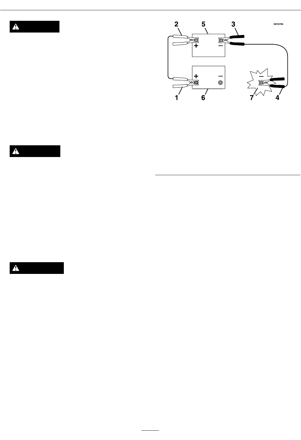
Figure19
1.Positive(+)cableondischargedbattery
2.Positive(+)cableonboosterbattery
3.Negative(–)cableontheboosterbattery
4.Negative(–)cableontheengineblock
5.Boosterbattery
6.Dischargedbattery
7.Engineblock
4.Connecttheotherendofthepositivecabletothe
positiveterminaloftheboosterbattery.
5.Connecttheblacknegative(–)cabletotheother
terminal(negative)oftheboosterbattery.
6.MAKETHEFINALCONNECTIONON
THEENGINEBLOCKOFTHESTALLED
VEHICLE(NOTTOTHENEGATIVEPOST)
AWAYFROMTHEBATTERY .STANDBACK.
7.Startthevehicleandremovethecablesinthe
reverseorderofconnection(theengineblock
(black)connectionisthersttodisconnect).
CheckMowerBlades
ServiceInterval:Beforeeachuseordaily
1.Stopengine,waitforallmovingpartstostop,and
removekey.Engageparkingbrake.
2.Liftdeckandsecureinraisedpositionasstatedin
theCleanGrassBuild-UpUnderDecksection.
3.Inspectbladesandsharpenorreplaceasrequired.
4.Reinstalltheblades(iftheywereremoved)inthe
followingorder:
A.Installthesplinedbushingthroughtheblade
withthebushingangeonbottom(grass)
sideofblade.
29
Maintenance
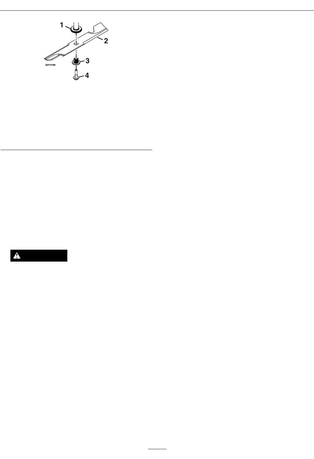
Figure20
1.Spindle
2.Blade
3.Splinedbushing
4.Bladeboltwasherassembly—T orqueto50-60ft-lb
(68-81N-m)Applylubricanttothreadsasneededto
preventseizing.Copper-basedanti-seizepreferable.
Greaseacceptablesubstitute.
B.Applylubricanttothethreadsoftheblade
boltasneededtopreventseizing.Copper
basedanti-seizeispreferable.Greaseisan
acceptablesubstitute.
C.Installthesplinedbushing/bladeassembly
andbladeboltwasherassemblyintothe
spindle.Installbladeboltngertight.
D.Placewrenchonthetopspindlenutthen
torquethebladeboltsto50-60ft-lb(68-81
N-m).
WARNING
Incorrectinstallationofthebladeor
componentsusedtoretainthebladecan
bedangerous.Failuretousealloriginal
componentsandassembledasshowncould
allowabladeorbladecomponenttobe
thrownoutfromunderthedeckresultingin
seriouspersonalinjuryordeath.
AlwaysinstalltheoriginalExmarkblades,
bladebushings,andbladeboltsasshown.
CheckSafetyInterlock
System
ServiceInterval:Beforeeachuseordaily
Note:Topreventenginecut-outsonroughterrain
theseatkillswitchhasa1/2seconddelay.
1.Checkstartingcircuit.Startershouldcrankwith,
parkingbrakeengaged,PTOdisengagedand
motioncontrolleversmovedoutintheneutral
lockposition.Theoperatordoesnotneedtobe
intheseattostarttheengine.
Trytostartwithoperatorinseat,parkingbrake
disengaged,PTOdisengagedandmotioncontrol
leversintheneutrallockposition-startermust
notcrank.
Trytostartwithoperatorinseat,parkingbrake
engaged,PTOengagedandmotioncontrol
leversintheneutrallockposition-startermust
notcrank.
Trytostartwithoperatorinseat,parking
brakeengaged,PTOdisengaged,andtheleft
motioncontrolleverin,startermustnotcrank,
repeatagainwiththerightleverin,thenwith
bothleversin-startermustnotcrank.
2.Checkthekillcircuits.Runengineatone-third
throttle,disengageparkingbrakeandraiseoff
ofseat(butdonotgetoffofmachine)engine
mustinitiateshutdownafterapproximately1/2
secondhaselapsed(seathastimedelaykillswitch
topreventcut-outsonroughterrain).
Runengineatone-thirdthrottle,engagePTO
andraiseoffofseat(butdonotgetoffof
machine)enginemustinitiateshutdownafter
onesecondhaselapsedifthehandlesarein.The
delaywillbe1/2secondifthehandlesareout.
Runengineatone-thirdthrottle,withbrake
disengaged,moveleversinandraiseoffseat(but
donotgetoffofmachine)enginemustinitiate
shutdownafter1/2secondhaselapsed.
Again,runengineatone-thirdthrottle,brake
engaged,andmoveleftmotioncontrollever
in-enginemustinitiateshutdownafter1/2
secondhaselapsed.
Repeatagainmovingtherightleverin,then
movingbothleversin-enginemustinitiate
shutdownafter1/2secondhaselapsedwhether
operatorisonseatornot.
Note:Ifmachinedoesnotpassanyofthesetests,
donotoperate.ContactyourauthorizedEXMARK
SERVICEDEALER.
Important:Itisessentialthatoperatorsafety
mechanismsbeconnectedandinproper
operatingconditionpriortouseformowing.
30
Maintenance
CheckRolloverProtections
Systems(RollBar)Knobs
ServiceInterval:Beforeeachuseordaily
Checkthatboththemountinghardwareandthe
knobsareingoodworkingcondition.Makesurethe
knobsarefullyengagedwiththeROPSintheraised
position.Theupperhoopoftherollbarmayneed
tobepushedforwardorpulledrearwardtogetboth
knobsfullyengaged.
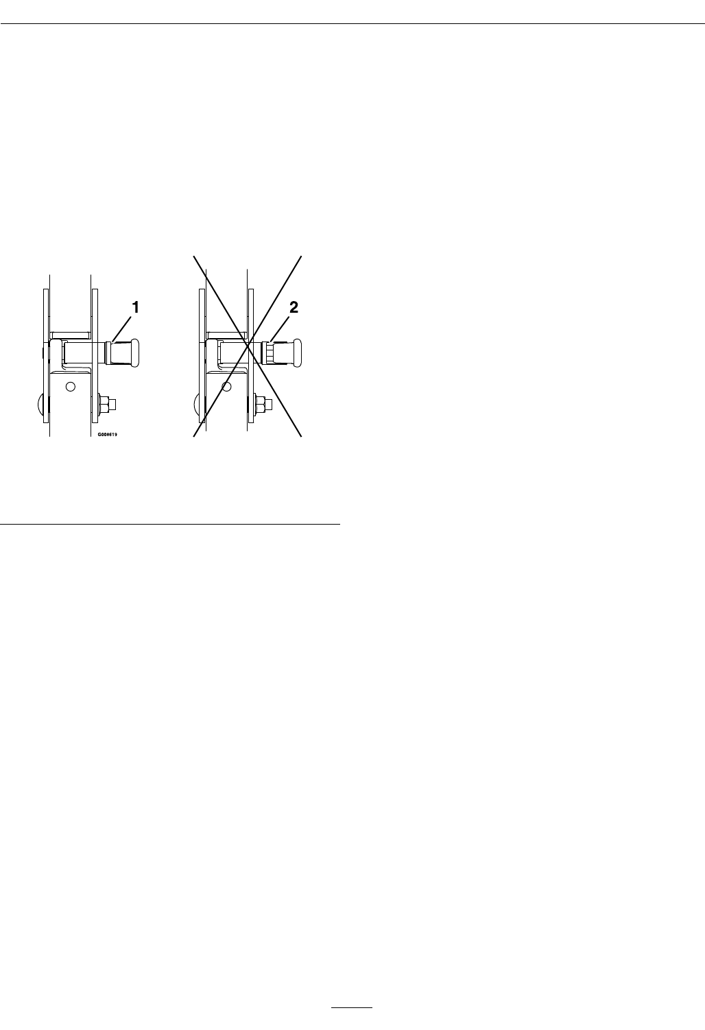
Figure21
1.Engaged2.Partiallyengaged—Do
NotoperatewithROPS
inthiscondition.
CheckSeatBelt
ServiceInterval:Beforeeachuseordaily
Visuallyinspectseatbeltforwear,cuts,andproper
operationofretractorandbuckle.Replacebefore
operatingifdamaged.
CheckforLooseHardware
ServiceInterval:Beforeeachuseordaily
1.Stopengine,waitforallmovingpartstostop,and
removekey.Engageparkingbrake.
2.Visuallyinspectmachineforanyloosehardware
oranyotherpossibleproblem.Tightenhardware
orcorrecttheproblembeforeoperating.
ServiceAirCleaner
ServiceInterval:Every250hours—Replace
theprimaryaircleaner
element—check
secondaryaircleaner
element;replaceifdirty.
(Mayneedmoreoften
undersevereconditions.
SeetheEngineOwner's
Manualforadditional
information.)
Every500hours—Replace
thesecondaryaircleaner
element(Mayneedmore
oftenundersevere
conditions.Seethe
EngineOwner'sManual
foradditionalinformation.)
1.Stopengine,waitforallmovingpartstostop,and
removekey.Engageparkingbrake.
2.SeetheEngineOwner'sManualformaintenance
instructions.
ChangeEngineOil
ServiceInterval:Aftertherst5hours
Every100hours/Yearly
(whichevercomesrst)
(Mayneedmoreoften
undersevereconditions.)
1.Stopengine,waitforallmovingpartstostop,and
removekey.Engageparkingbrake.
2.Drainoilwhileengineiswarmfromoperation.
3.TheoildrainhoseonKawasakienginesislocated
onrighthandsideofengineattherear.Itis
locatedonthelefthandsideforKohlerengines.
Placepanundermachinetocatchoil.Remove
plugfromendofdrainhose.Allowoiltodrain
andreplaceoildrainplug.Torqueplugto20-24
ft-lb.
4.Replacetheoilltereveryotheroilchange.Clean
aroundoillterandunscrewltertoremove.
Beforereinstallingnewlter,applyathincoating
ofExmark4–CyclePremiumEngineoilonthe
surfaceoftherubberseal.Turnlterclockwise
untilrubbersealcontactsthelteradapterthen
tightenlteranadditional1/2to3/4turn.
5.Cleanaroundoilllcapandremovecap.Fillto
speciedcapacityandreplacecap.
6.UseoilrecommendedintheCheckEngineOil
Levelsection.DoNotoverll.Starttheengine
andcheckforleaks.
7.Wipeupanyspilledoilfromenginedeck
mountingsurfaces.
31
Maintenance
CheckHydraulicOilLevel
ServiceInterval:Beforeeachuseordaily
1.Stopengineandwaitforallmovingpartstostop.
Engageparkingbrake.
2.Waituntiltheunitcoolsbeforecheckingthe
hydraulicoil.
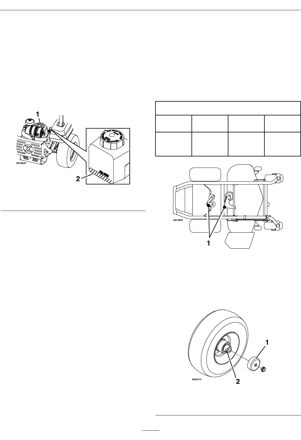
3.Checkexpansiontankandifnecessaryadd
ExmarkPremiumHydroOiltotheFULLCOLD
line(seeFigure22).
Figure22
1.Engine2.Expansiontank
CheckTirePressures
ServiceInterval:Every50hours
1.Stopengine,waitforallmovingpartstostop,and
removekey.Engageparkingbrake.
2.Checktirepressureindrivetires.
3.Inatedrivetiresto13psi(90kPa).
4.Checktirepressureincastertires.
5.Inatecastertiresto13psi(90kPa).
CheckConditionOfBelts
ServiceInterval:Every50hours
1.Stopengine,waitforallmovingpartstostop,and
removekey.Engageparkingbrake.
2.Removeleftandrightbeltshieldsondeckand
lowerthedecktoinspectdeckdrivebelt.
3.Checkundermachinetoinspectthepumpdrive
belt.
Note:Noadjustmentsarerequiredforbelt
tension.
LubricateGreaseFittings
Note:Seechartforserviceintervals.
1.Stopengine,waitforallmovingpartstostop,and
removekey.Engageparkingbrake.
2.Lubricatettingswithonetotwopumpsof
NGLIgrade#2multi-purposegungrease.
Refertothefollowingchartforttinglocations
andlubricationschedule.
LubricationChart
Fitting
Locations
Initial
Pumps
Numberof
Places
Service
Interval
1.Deckand
PumpIdler
Pivots
1250hours
LubricateCasterWheelHubs
ServiceInterval:Asrequired
1.Stopengine,waitforallmovingpartstostop,and
removekey.Engageparkingbrake.
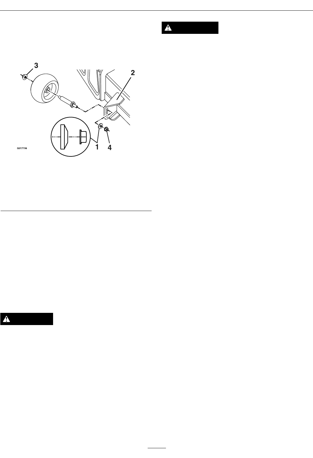
Figure23
1.Sealguard2.Spacernutwithwrench
ats
32

Maintenance
2.Removecasterwheelfromcasterforks.
3.Removesealguardsfromthewheelhub.
4.Removeoneofthespacernutsfromtheaxle
assemblyinthecasterwheel.Notethatthread
lockingadhesivehasbeenappliedtolockthe
spacernutstotheaxle.Removetheaxle(withthe
otherspacernutstillassembledtoit)fromthe
wheelassembly.
5.Pryoutseals,andinspectbearingsforwearor
damageandreplaceifnecessary.
6.PackthebearingswithaNGLIgrade#1
multi-purposegrease.
7.Insertonebearing,onenewsealintothewheel.
Note:Seals(ExmarkP/N103-0063)mustbe
replaced.
8.Iftheaxleassemblyhashadbothspacernuts
removed(orbrokenloose),applyathreadlocking
adhesivetoonespacernutandthreadontothe
axlewiththewrenchatsfacingoutward.Do
Notthreadspacernutallofthewayontotheend
oftheaxle.Leaveapproximately1/8inch(3mm)
fromtheoutersurfaceofthespacernuttothe
endoftheaxleinsidethenut.
9.Inserttheassemblednutandaxleintothewheel
onthesideofthewheelwiththenewsealand
bearing.
10.Withtheopenendofthewheelfacingup,ll
theareainsidethewheelaroundtheaxlefullof
NGLIgrade#1multi-purposegrease.
11.Insertthesecondbearingandnewsealintothe
wheel.
12.Applyathreadlockingadhesivetothe2ndspacer
nutandthreadontotheaxlewiththewrenchats
facingoutward.
13.Torquethenutto75-80in-lb(8-9N-m),loosen,
thenre-torqueto20-25in-lb(2-3N-m).Make
sureaxledoesnotextendbeyondeithernut.
14.Reinstallthesealguardsoverthewheelhuband
insertwheelintocasterfork.Reinstallcasterbolt
andtightennutfully.
Important:Topreventsealandbearingdamage,
checkthebearingadjustmentoften.Spinthe
castertire.Thetireshouldnotspinfreely
(morethan1or2revolutions)orhaveanyside
play.Ifthewheelspinsfreely,adjusttorqueon
spacernutuntilthereisaslightamountofdrag.
Reapplythreadlockingadhesive.
CheckSparkPlugs
ServiceInterval:Every200hours
Removesparkplugs,checkconditionandresetgaps,
orreplacewithnewplugs.SeeEngineOwner's
Manual.
ChangeFuelFilter
ServiceInterval:Asrequired
Afuellterisinstalledbetweenthefueltankandthe
engine.Replacewhennecessary.
ReplacementFilters
KawasakiKawasaki
P/N49019-7005
KohlerKohler
P/N2405013
Note:Itisimportanttoreinstallthefuellinehoses
andsecurewithplastictiesthesameastheywere
originallyinstalledatthefactorytokeepthefuelline
awayfromcomponentsthatcouldcausefuelline
damage.
ChangeHydraulicSystem
FilterandFluid
ServiceInterval:Aftertherst100hours
Every500hoursthereafter
(Every250hoursifusing
Mobil115W50)
1.Stopengine,waitforallmovingpartstostop,and
allowenginetocool.Removekeyandengage
parkingbrake.
2.Locatethetwoltersunderthetransmissions.
Removelterguards.
3.Carefullycleanareaaroundlters.Itisimportant
thatnodirtorcontaminationenterhydraulic
system.
4.Unscrewlterstoremoveandallowoiltodrain
fromdrivesystem.
Important:Beforereinstallingnewlters,
applyathincoatofExmarkPremiumHydro
Oilonthesurfaceoftheltersrubberseal.
Turntheltersclockwiseuntilrubberseal
contactsthelteradapterthentightenthelter
anadditional3/4to1fullturn.
33
Maintenance
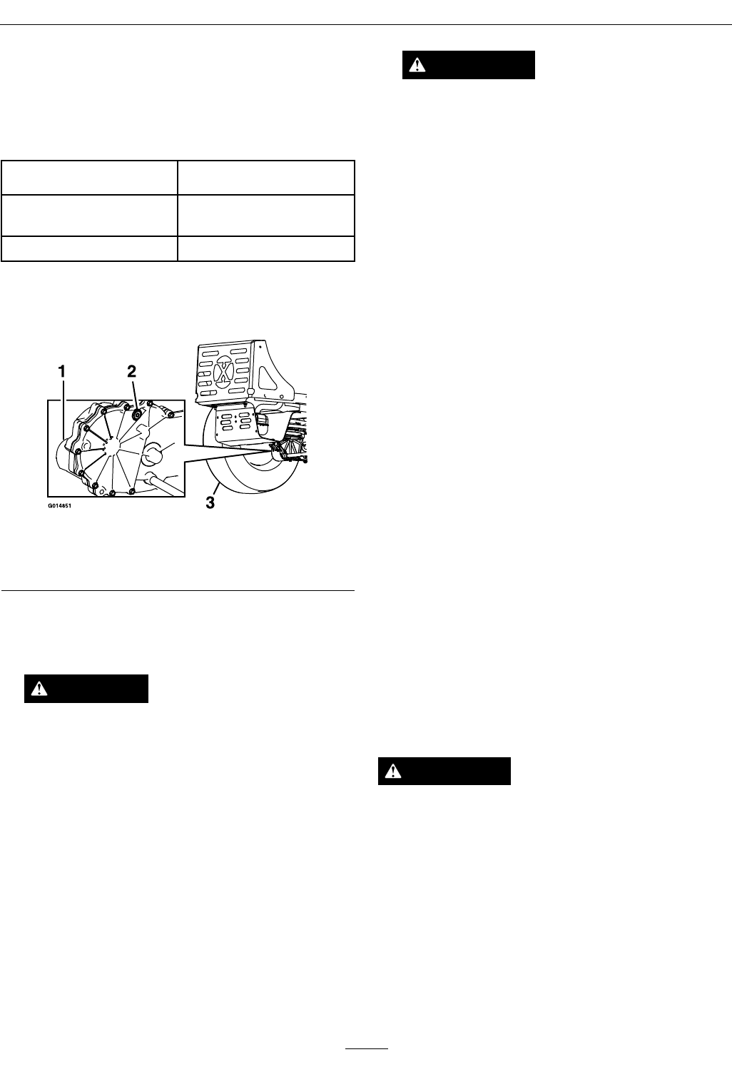
5.Removetheventplugoneachtransmissionand
llthroughexpansionreservoir,whenoilcomes
outofventreinstallplug.
ExmarkPremiumHydroOilisrecommended.
Refertothechartforanacceptablealternative:
HydroOilChangeInterval
ExmarkPremiumHydro
Oil(Preferred)
500Hours
Mobil115W50250Hours
Torqueplugsto180in-lb(244N-m).Continueto
addoiluntilitreachestheFULLCOLDlineon
theexpansionreservoir.
Figure24
1.Oillter3.Leftreartire
2.Ventplug
6.Raisetherearofmachineupandsupportwith
jackstands(orequivalentsupport)justhigh
enoughtoallowdrivewheelstoturnfreely.
CAUTION
Raisingthemowerdeckforserviceor
maintenancerelyingsolelyonmechanical
orhydraulicjackscouldbedangerous.The
mechanicalorhydraulicjacksmaynotbe
enoughsupportormaymalfunctionallowing
theunittofall,whichcouldcauseinjury.
DoNotrelysolelyonmechanicalorhydraulic
jacksforsupport.Useadequatejackstands
orequivalentsupport.
7.Startengineandmovethrottlecontrolaheadto
1/2throttleposition.Disengageparkingbrake.
WARNING
Enginemustberunninganddrivewheels
mustbeturningsoadjustmentscanbe
performed.Contactwithmovingpartsorhot
surfacesmaycausepersonalinjury.
Keepngers,hands,andclothingclearof
rotatingcomponentsandhotsurfaces.
A.Withthebypassvalveopenandtheengine
running,slowlymovethedirectionalcontrol
inbothforwardandreverse(5or6times).
B.Withthebypassvalveclosedandtheengine
running,slowlymovethedirectionalcontrol
inbothforwardandreversedirections(5to
6times).Checktheoillevel,andaddoilas
requiredafterstoppingtheengine.
C.ItmaybenecessarytorepeatstepsAandB
untilalltheairiscompletelypurgedfrom
thesystem.Whenthetransaxleoperatesat
normalnoiselevelsandmovessmoothly
forwardandreverseatnormalspeeds,then
thetransaxleisconsideredpurged.
Note:DoNotchangethehydraulicsystemoil
(exceptforwhatcanbedrainedwhenchanginglter),
unlessitisfelttheoilhasbeencontaminatedorbeen
extremelyhot.
Changingoilunnecessarilycoulddamagehydraulic
systembyintroducingcontaminantsintothesystem.
CheckSparkArrester
(ifequipped)
ServiceInterval:Every50hours
WARNING
Hotexhaustsystemcomponentsmayignite
gasolinevaporsevenaftertheengineisstopped.
Hotparticlesexhaustedduringengineoperation
mayigniteammablematerials.Firemayresult
inpersonalinjuryorpropertydamage.
DoNotrefuelorrunengineunlesssparkarrester
isinstalled.
1.Stopengine,waitforallmovingpartstostop,and
removekey.Engageparkingbrake.
2.Waitformufertocool.
34
Maintenance
3.Ifanybreaksinthescreenorweldsareobserved,
replacearrester.
4.Ifpluggingofthescreenisobserved,remove
arresterandshakelooseparticlesoutofthe
arresterandcleanscreenwithawirebrush(soak
insolventifnecessary).Reinstallarresteron
exhaustoutlet.
ThreadLockingAdhesives
Threadlockingadhesivessuchas“Loctite242”
or“Fel-Pro,Pro-LockNutType”areusedonthe
followingfasteners:
•ROPSspringpinhousing.
•Sheaveandclutchretainingboltintheendof
enginecrankshaft.
•Hydrocrossmembermountingbolts
Threadlockingadhesivesarerequiredforsome
hardwareonengines—seetheEnginemanual.
Copper-BasedAnti-seize
Copper-basedanti-seizeisusedinthefollowing
location:
OnthreadsofBladeBolts.SeeCheckMower
Bladessection.
DielectricGrease
Dielectricgreaseisusedonallbladetypeelectrical
connectionstopreventcorrosionandlossofcontact.
Dielectricgreaseshouldnotbeappliedtosealed
connectors.
Adjustments
Note:DisengagePTO,shutoffengine,waitfor
allmovingpartstostop,engageparkingbrake,and
removekeybeforeservicing,cleaning,ormakingany
adjustmentstotheunit.
CAUTION
Raisingthemowerdeckforserviceor
maintenancerelyingsolelyonmechanical
orhydraulicjackscouldbedangerous.The
mechanicalorhydraulicjacksmaynotbeenough
supportormaymalfunctionallowingtheunitto
fall,whichcouldcauseinjury.
DoNotrelysolelyonmechanicalorhydraulic
jacksforsupport.Useadequatejackstandsor
equivalentsupport.
DeckLeveling
1.Positionthemoweronaatsurface.
2.Stopengine,waitforallmovingpartstostop,and
removekey.Engageparkingbrake.
3.Checkthetirepressureinthedrivetires.Proper
inationpressurefortiresis13psi(90kPa).
Adjustifnecessary.
4.Positionthetransportlockinthelatching
position.
5.Carefullyrotatethebladesfromsidetoside.
6.Measurebetweentheoutsidecuttingedgesand
theatsurface(Figure25andFigure26).Ifboth
measurementsarenotwithin3/16inch(5mm),
anadjustmentisrequired;continuewiththis
procedure.
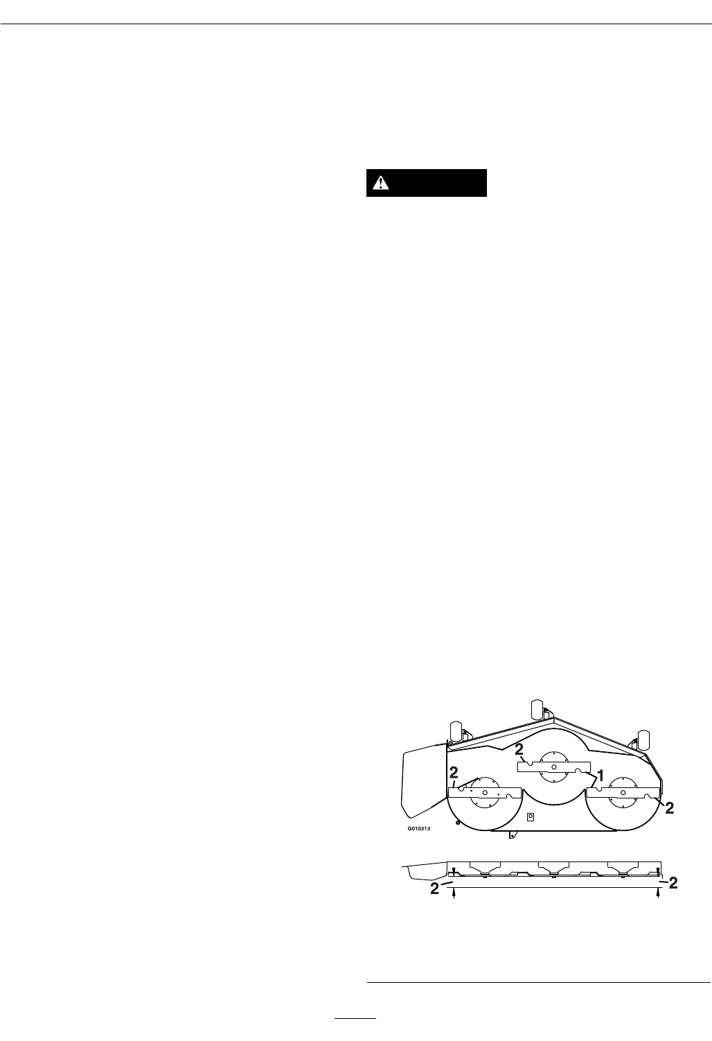
Figure25
48,52,and60InchDecks
1.Bladessidetoside2.Measurehere
35
Maintenance
Figure26
44InchDeck
1.Bladessidetoside2.Measurehere
7.Setanti-scalprollerstotopholesorremove
completelyforthisadjustment.
8.Settheheight-of-cutlevertothe3inch(76mm)
position.Placetwo“B”thickblocks(seeBlock
HeightandRakeTable)undertherearedgeofthe
cuttingdeckskirt;oneoneachsideofthecutting
deck.Placetwo“A”thickblocksundereachside
ofthefrontedgeofthedeck,butnotunderthe
anti-scalprollerbrackets.
BlockHeightandRakeTable
Deck
Size
FrontBlock
Height“ A ”
RearBlock
Height“B”
Rake“R”
442.69inches
(6.8cm)
2.99inches
(7.6cm)
1/8–3/8inch
(3.2–9.5mm)
48,52,
&60
2.77inches
(7.0cm)
2.81inches
(7.1cm)
1/16–5/16inch
(1.6–7.9mm)
9.Carefullyrotatethebladessidetoside
(Figure25andFigure26).
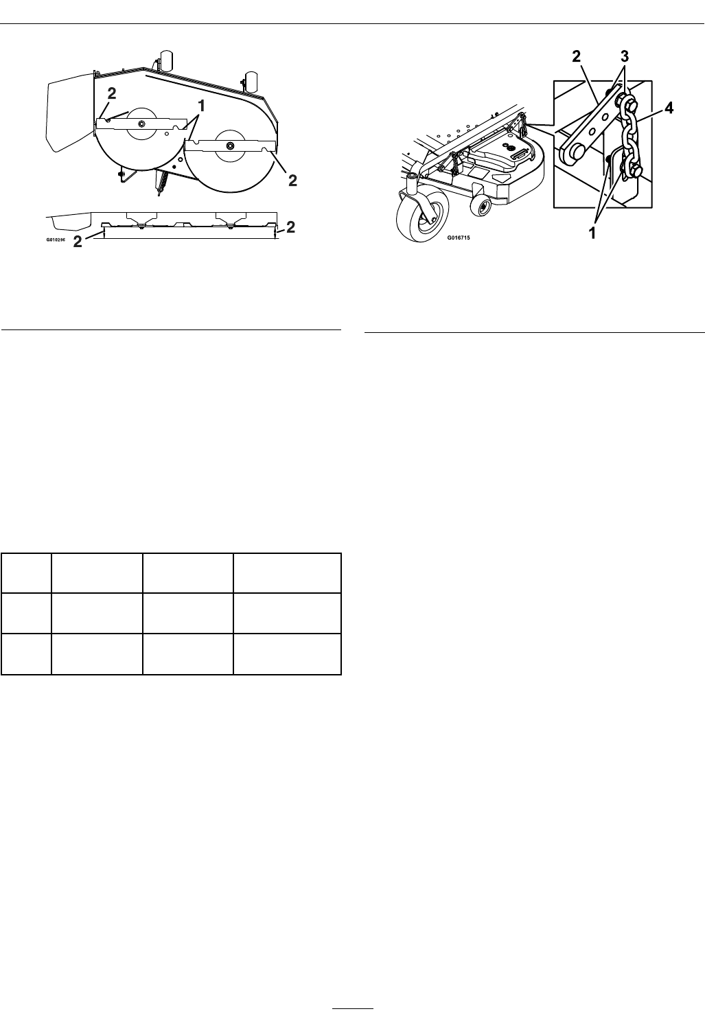
10.Loosenthelevelingadjustlockingnuts(item1
Figure27)onallfourcornerssothatthedeckis
sittingsecurelyonallfourblocks.Makesurethat
theslackisremovedfromthedeckhangersand
thedeckliftfootleverispushedbackagainstthe
stop,thentightenthefourlevelingadjustlocking
nuts.
Figure27
1.Levelingadjustlocking
nuts
3.Deckhanger
2.Deckliftarm4.Chain
11.Recheckthatblockstjustsnuglyunderthedeck
skirt.Makesureallattachmentboltsaretight
12.Continuelevelingthedeckbycheckingthe
front-to-rearbladeslope;refertoAdjustingthe
BladeSlope.
13.Recheckbladesforlevelnessandrepeatdeck
levelingprocedureifnecessary.
AdjustingtheBladeSlope
1.Checkthefront-to-rearbladelevelanytimeyou
installthemower.Ifthefrontbladetipisnot
“R”(seeBlockHeightandRakeTableinDeck
Leveling)lowerthantherearbladetip,adjustthe
bladelevelusingthefollowinginstructions:
2.Parkthemachineonalevelsurfaceanddisengage
thebladecontrolswitch.
3.Movethemotioncontrolleversoutwardtothe
neutralposition,engagetheparkingbrake,stop
theengine,removethekey,andwaitforall
movingpartstostopbeforeleavingtheoperating
position.
4.Checktheairpressureofallfourtires.Ifneeded,
adjusttotherecommendedination;referto
CheckingtheTirePressureinDriveSystem
Maintenancesection.
5.Checkandadjusttheside-to-sidebladelevelif
youhavenotcheckedthesetting;refertoDeck
Leveling.
6.Settheheight-of-cutlevertothe3inch(76mm)
position.Placetwo“B”thickblocks(seeBlock
HeightandRakeTableinDeckLeveling)under
therearedgeofthecuttingdeckskirt;oneon
36
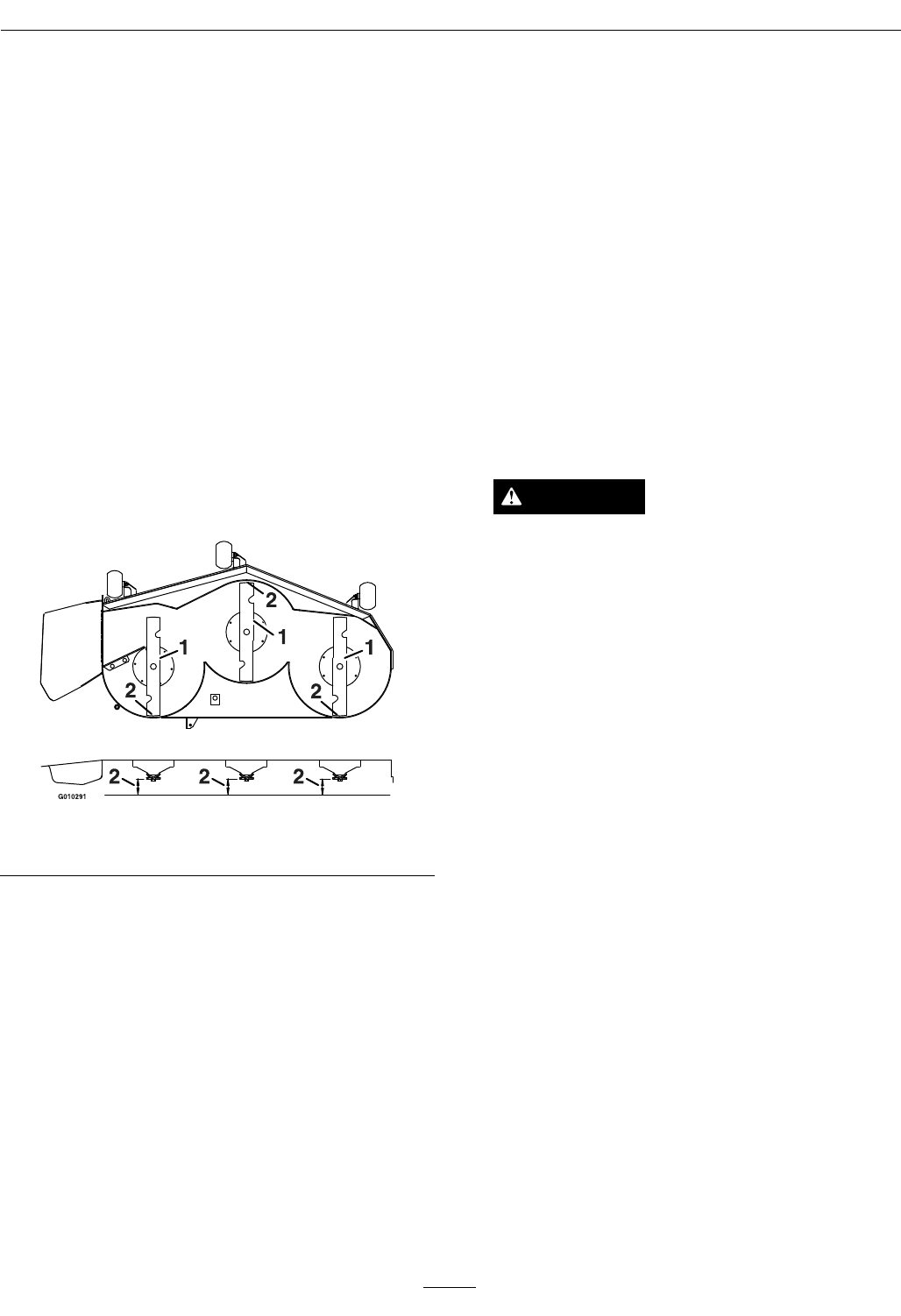
Maintenance
eachsideofthecuttingdeck.Placetwo“ A”thick
blocks(seeBlockHeightandRakeTableinDeck
Leveling)undereachsideofthefrontedgeofthe
deck,butnotundertheanti-scalprollerbrackets.
7.Loosenthelevelingadjustlockingnuts(item1
Figure27)onallfourcornerssothatthedeckis
sittingsecurelyonallfourblocks.Makesurethat
theslackisremovedfromthedeckhangersand
thedeckliftfootleverispushedbackagainstthe
stop,thentightenthefourlevelingadjustlocking
nuts.
8.Carefullyrotatethebladessotheyarefacingfront
torear(Figure28).
9.Measurefromthetipofthefrontbladetotheat
surfaceandthetipoftherearbladetotheat
surface(Figure28).Ifthefrontbladetipisnot
“R”(seeBlockHeightandRakeTableinDeck
Leveling)lowerthantherearbladetip,adjustthe
frontdeckhanger.
Figure28
1.Bladesfronttorear2.Measurehere
10.Whenthefront-to-rearbladeslopeiscorrect
checktheside-to-sidelevelofthemoweragain;
refertoDeckLeveling.
PumpDriveBeltTension
Self-tensioning-Noadjustmentnecessary.
DeckBeltTension
Self-tensioning-Noadjustmentnecessary.
AdjustingtheParkingBrake
ServiceInterval:Every500hours
Checktomakesurebrakeisadjustedproperly.This
proceduremustbefollowedaftertherst100hours
orwhenabrakecomponenthasbeenremovedor
replaced.
1.Drivethemachineontoalevelsurface.
2.Disengagethebladecontrolswitch(PTO),move
themotioncontrolleverstotheneutrallocked
positionandsettheparkingbrake.
3.Stoptheengine,waitforallmovingpartstostop,
andremovethekey.
4.Setupthemachinetobepushedbyhand(see
DriveWheelReleaseValvesintheOperation
section).
5.Raisethebackofthemachineupandsupportthe
machinewithjackstands.
CAUTION
Raisingthemowerdeckforserviceor
maintenancerelyingsolelyonmechanical
orhydraulicjackscouldbedangerous.The
mechanicalorhydraulicjacksmaynotbe
enoughsupportormaymalfunctionallowing
theunittofall,whichcouldcauseinjury.
DoNotrelysolelyonmechanicalorhydraulic
jacksforsupport.Useadequatejackstands
orequivalentsupport.
6.Engage/disengagethebrakeandcheckeachdrive
tiretomakesureeachbrakeengages/disengages.
7.Ifadjustmentisnecessary,loosenthejamnut
fromtheyokeonthesidethatneedsadjustment.
Removethehairpinandclevispin(seeFigure29).
37
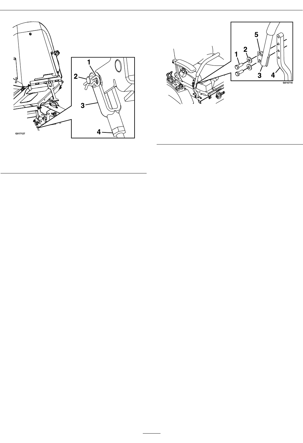
Maintenance
Figure29
1.Hairpin3.Yoke
2.Clevispin4.Jamnut
•AdjustingtheBraketoEngage:Shortenthe
linkagebyturningtheyokeclockwise.
•AdjustingtheBraketoDisengage:
Lengthenthelinkagebyturningtheyoke
counterclockwise.
8.Reinstalltheclevispinandhairpinandtighten
downthejamnut.Repeatstep6andreadjustif
necessary.
9.Whenadjustmentiscomplete,removethejack
standsorequivalentsupportandlowerthe
machine.
10.Placethemachineintothe“operating”position.
RefertotheDriveWheelReleaseValvessection
inOperation.
MotionControlHandle
Adjustment
Adjustingtheheight:
Themotioncontrolleverscanbeadjustedhigheror
lowerformaximumoperatorcomfort.
1.Removethehardwareholdingthecontrolleverto
thecontrolarmshaft(Figure30).
Figure30
1.Bolts4.Controlarmshaft
2.Washer5.Slottedhole
3.Controllever
2.Movethecontrollevertothenextsetofholes.
Securetheleverwiththehardware.
3.Repeattheadjustmentfortheoppositecontrol
lever.
AdjustingtheTilt
Themotioncontrolleverscanbetiltedforeoraftfor
maximumoperatorcomfort.
1.Loosentheupperboltholdingthecontrollever
tothecontrolarmshaft.
2.Loosenthelowerboltjustenoughtopivotthe
controlleverforeoraftFigure30.Tightenboth
boltstosecurethecontrolinthenewposition.
3.Repeattheadjustmentfortheoppositecontrol
lever.
FullForwardTracking
Adjustment
Ifthemachinetravelsorpullstoonesidewhenthe
motioncontrolleversareinthefullforwardposition,
adjustthecoverplates.
1.Loosenthescrewsonacoverplate(seeFigure31).
2.Slidethecoverplatebackwardorforwardto
adjustthetraveloftheleverandtightenthe
screws.
3.Drivethemachineandcheckthefullforward
tracking.
4.Repeatsteps1through3untildesiredtracking
isobtained.
38
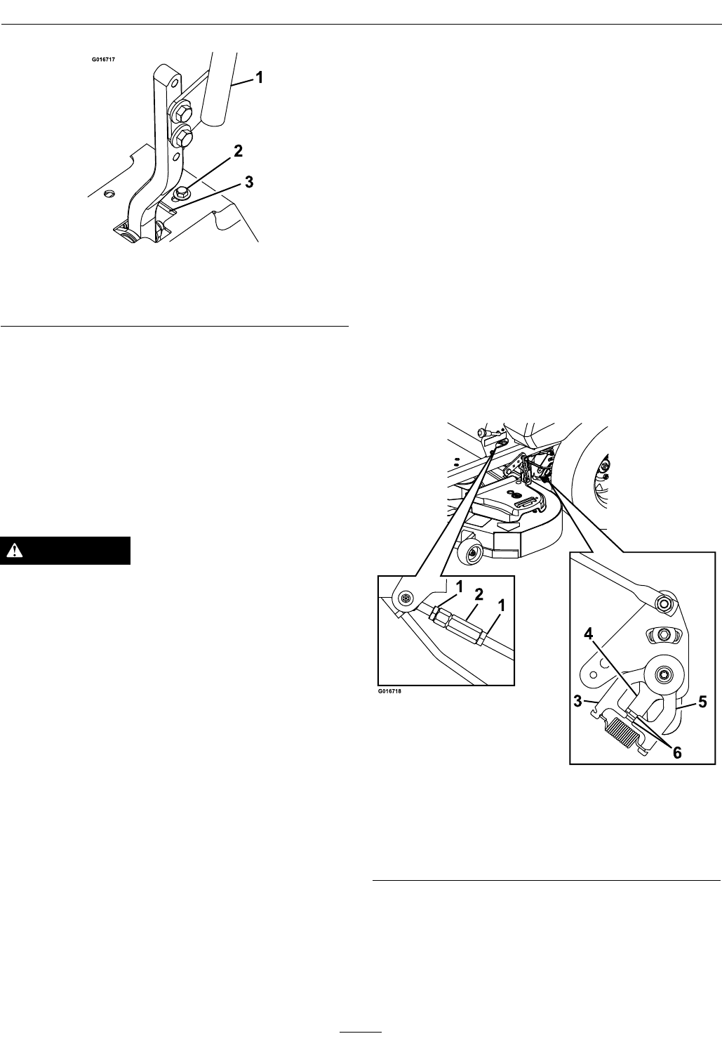
Maintenance
Figure31
1.Controlarmshaft3.Trackingplate
2.Trackingplatescrew
MotionControlLinkage
Adjustment
Locatedoneithersideoftheunit,belowtheseatare
thepumpcontrollinkages.Rotatingtheturnbuckle
witha1/2inchwrenchallowsnetuningadjustments
sothatthemachinedoesnotmoveinneutral.Any
adjustmentsshouldbemadeforneutralpositioning
only.
WARNING
Enginemustberunninganddrivewheelsmust
beturningsoadjustmentscanbeperformed.
Contactwithmovingpartsorhotsurfacesmay
causepersonalinjury.
Keepngers,hands,andclothingclearof
rotatingcomponentsandhotsurfaces.
1.Priortostartingtheengine,pushthedecklift
pedalandremovetheheightofcutpin.Lower
decktotheground.
2.Raisetherearofmachineupandsupportwith
jackstands(orequivalentsupport)justhigh
enoughtoallowdrivewheelstoturnfreely.
3.Removetheelectricalconnectionfromtheseat
safetyswitch,locatedunderthebottomcushion
oftheseat.Theswitchisapartoftheseat
assembly.
4.Temporarilyinstallajumperwireacrossthe
terminalsintheconnectorofthemainwiring
harness.
5.Startengine.Brakemustbeengagedand
motioncontrolleversouttostartengine.
Operatordoesnothavetobeintheseat.Run
engineatfullthrottleandreleasebrake.
6.Runtheunitatleast5minuteswiththedrive
leversatfullforwardspeedtobringhydraulicoil
uptooperatingtemperature.
Note:Themotioncontrolleverneedstobein
neutralwhilemakinganynecessaryadjustments.
7.Bringthemotioncontrolleversintotheneutral
position.Thecontrolplatetabsshouldtouchthe
returntoneutralplatesonthehydros.Adjust
pumpcontrolrodlengthsbylooseningthenuts
androtatingtheturnbuckleintheappropriate
directionuntilthewheelsslightlycreepinreverse
(Figure32).Movethemotioncontrolleverstothe
reversepositionandwhileapplyingslightpressure
totheleverallowthereverseindicatorspringsto
bringtheleversbacktoneutral.Thewheelsmust
stopturningorslightlycreepinreverse.
Figure32
1.Nut4.Controlplate
2.Turnbuckle5.Returntoneutralplate
3.Stationaryplate6.Tabstouchingreturnto
neutralplate
8.Tightennuts.
9.Shutoffunit.Removejumperwirefromwire
harnessandplugconnectorintoseatswitch.
10.Removethejackstands.
39
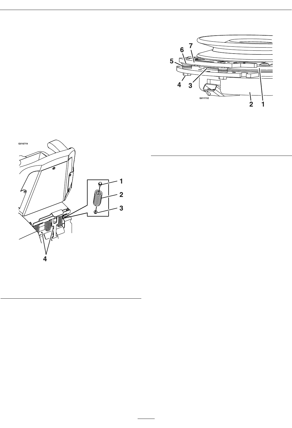
Maintenance
11.Raisethedeckandre-installtheheightofcutpin.
12.Checkthatthemachinedoesnotcreepinneutral
withtheparkbrakedisengaged.
AdjustingtheSeatRide
Suspension
Thenumberofseatspringscanbechangedto
maximizeridercomfort.Morespringsshouldbeused
withheavieroperatorsandonroughterrain.Fewer
springsshouldbeusedwithlighteroperatorsand
whenmowingsmooth,wellestablishedlawns.Always
keepthenumberofspringsontheleftandrightside
thesamewhenaddingandremovingsprings.
Figure33
1.Bolt3.Nut
2.Spring4.Additionalmounting
holes
Uptovespringscanbesecuredtotheseatboxwith
anutandbolt,seeFigure33.
RefertothePartsManualforspringandhardware
partnumbers.
ElectricClutchAdjustment
Figure34
1.Armature5.Brakespacer
2.Fieldshell6.Re-gapshim
3.Rotor7.Brakepole
4.Brakemountingbolt
RemovingtheShim:
1.Stopengine,waitforallmovingpartstostop,
andremovekey.Engageparkingbrake.Allow
themachinetocoolcompletelybeforestarting
theseinstructions.
2.Usingapneumaticline,blowoutanydebris
fromunderthebrakepoleandaroundthebrake
spacers.
3.Checktheconditionofthewireharnessleads,
connectors,andterminals.Cleanorrepairas
necessary.
4.Verifythat12Vispresentattheclutchconnector
whenthePTOswitchisengaged.
5.Measurethegapbetweentherotorandarmature.
Ifthegapisgreaterthan.04inch(1mm),proceed
withthefollowingsteps:
A.Loosenbothbrakemountingboltsone-half
toonefullturn(seeFigure35).
Note:DoNotremovethebrakepolefrom
theeldshell/armature.Thebrakepolehas
worntomatchthearmatureandneedsto
continuetomatchaftertheshimisremoved
toensureproperbraketorque.
40
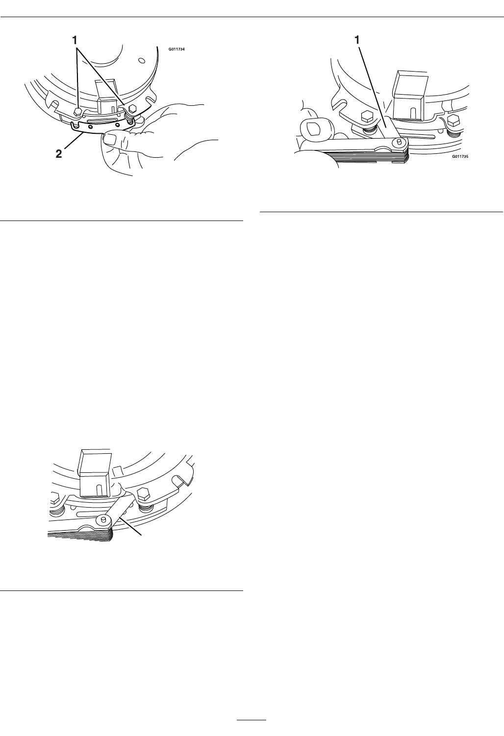
Maintenance
Figure35
1.Brakemountingbolt2.Shim
B.Usingneedlenosepliers,orbyhand,take
holdofthetabandremovetheshim(DoNot
discardtheshimuntilproperclutchfunction
hasbeenconrmed).
C.Usingapneumaticline,blowoutanydebris
fromunderthebrakepoleandaroundthe
brakespacers.
D.Re-torqueeachbolt(M6x1)to10ft-lb(13
N-m)+/-0.5ft-lb(0.7N-m).
E.Usinga0.010inchthickfeelergauge,verify
thatagapispresentbetweentherotorand
armaturefaceonbothsidesofthebrakepole
asshown.(Duetothewaytherotorand
armaturefaceswear(peaksandvalleys)itis
sometimesdifculttomeasurethetruegap.)
G011733
1
Figure36
1.Feelergauge
Figure37
1.Feelergauge
•Ifthegapislessthan0.010inch,then
reinstalltheshimandreferencethe
Troubleshootingsection.
•Ifthegapissufcient,proceedtothe
safetycheckinstepF.
F.Performthefollowingsafetycheck:
a.Sitontheseatandstarttheengine.
b.MakesurethebladesDoNotengagewith
thePTOswitch“off”andtheclutch
disengaged.
Iftheclutchdoesnotdisengage,
reinstalltheshimandreferencethe
Troubleshootingsection.
c.EngageanddisengagethePTOswitch
tenconsecutivetimestoensuretheclutch
isfunctioningproperly.Iftheclutch
doesnotengageproperly,referencethe
Troubleshootingsection.
41

Maintenance
Cleaning
CleanEngineandExhaust
SystemArea
ServiceInterval:Beforeeachuseordaily
(Mayberequiredmore
oftenindryordirty
conditions.)
CAUTION
Excessivedebrisaroundenginecoolingair
intakeandexhaustsystemareacancauseengine,
exhaustarea,andhydraulicsystemtooverheat
whichcancreatearehazard.
Cleanalldebrisfromengineandexhaustsystem
area.
1.Stopengine,waitforallmovingpartstostop,and
removekey.Engageparkingbrake.
2.Cleanalldebrisfromrotatingengineairintake
screen,aroundengineshrouding,andexhaust
systemarea.
3.Wipeupanyexcessivegreaseoroilaroundthe
engineandexhaustsystemarea.
RemoveEngineShroudsand
CleanCoolingFins
ServiceInterval:Every100hours
1.Stopengine,waitforallmovingpartstostop,and
removekey.Engageparkingbrake.
2.Removecoolingshroudsfromengineandclean
coolingns.Alsocleandust,dirtandoilfrom
externalsurfacesofenginewhichcancause
inadequatecooling.
3.Makesurecoolingshroudsarereinstalled.
Operatingtheenginewithoutcoolingshroudswill
causeenginedamageduetooverheating.
CleanHydroFanCooling
Fins
ServiceInterval:Beforeeachuseordaily
Removingdebrisfromthehydrofancoolingnswill
allowthehydrosystemtoruncoolerandimprovethe
lifeofthehydrosystem.
1.Stopengine,waitforallmovingpartstostop,and
removekey.Engageparkingbrake.
2.Slideseatallthewayforward.
3.Removeaccumulateddebrisfromthehydrofan
coolingnsanduppersurfaces.
CleanDebrisFromMachine
ServiceInterval:Beforeeachuseordaily
1.Stopengine,waitforallmovingpartstostop,and
removekey.Engageparkingbrake.
2.Cleanoffanyoil,debris,orgrassbuild-uponthe
machineandcuttingdeck,especiallyunderdeck
beltshields,aroundthefueltank,aroundengine
andexhaustarea.
CleanGrassBuild-UpUnder
Deck
ServiceInterval:Beforeeachuseordaily
1.Parkthemachineonalevelsurfaceanddisengage
thebladecontrolswitch.
2.Stopengine,waitforallmovingpartstostop,and
removekey.Engageparkingbrake.
3.Raisedecktothetransport(5inch(12.7cm)
cuttingheight)position.Liftthefrontofunit
andsupportunitusingjackstandsorequivalent
support.
CAUTION
Raisingthemowerdeckforserviceor
maintenancerelyingsolelyonmechanical
orhydraulicjackscouldbedangerous.The
mechanicalorhydraulicjacksmaynotbe
enoughsupportormaymalfunctionallowing
theunittofall,whichcouldcauseinjury.
DoNotrelysolelyonmechanicalorhydraulic
jacksforsupport.Useadequatejackstands
orequivalentsupport.
4.Cleanoutanygrassbuild-upfromundersideof
deckandindischargedeector.
WasteDisposal
MotorOilDisposal
Engineoilandhydraulicoilarebothpollutantsto
theenvironment.Disposeofusedoilatacertied
42

Maintenance
recyclingcenteroraccordingtoyourstateandlocal
regulations.
BatteryDisposal
DANGER
Batteryelectrolytecontainssulfuricacid,which
ispoisonousandcancausesevereburns.
Swallowingelectrolytecanbefatalorifittouches
skincancausesevereburns.
•Wearsafetyglassestoshieldeyes,andrubber
glovestoprotectskinandclothingwhen
handlingelectrolyte.
•DoNotswallowelectrolyte.
•Intheeventofanaccident,ushwithwater
andcalladoctorimmediately.
Federallawstatesthatbatteriesshouldnotbeplaced
inthegarbage.Managementanddisposalpractices
mustbewithinrelevantfederal,state,orlocallaws.
Ifabatteryisbeingreplacedoriftheunitcontaining
thebatteryisnolongeroperatingandisbeing
scrapped,takethebatterytoalocalcertiedrecycling
center.Ifnolocalrecyclingisavailablereturnthe
batterytoanycertiedbatteryreseller.
43

Troubleshooting
Troubleshooting
Important:Itisessentialthatalloperatorsafetymechanismsbeconnectedandinproperoperating
conditionpriortomoweruse.
Whenaproblemoccurs,donotoverlookthesimplecauses.Forexample:startingproblemscouldbecaused
byanemptyfueltank.
Thefollowingtablelistssomeofthecommoncausesoftrouble.Donotattempttoserviceorreplacemajor
itemsoranyitemsthatcallforspecialtimingofadjustmentprocedures(suchasvalves,governor,etc.).Have
thisworkdonebyyourEngineServiceDealer.
Note:WhendisconnectingelectricalconnectorsDONOTpullonthewirestoseparatetheconnectors.
ProblemPossibleCauseCorrectiveAction
1.PTOisengaged.1.DisengagethePTO.
2.Parkingbrakeisnotengaged.2.Settheparkingbrake.
3.Driveleversarenotinneutrallock
position.
3.Ensurethedriveleversareintheneutral
lockposition.
4.Batterydoesnothaveafullcharge.4.Chargethebattery.SeeCheck
BatteryChargeandRecommended
JumpStartingProceduresectionsin
Maintenance.
5.Electricalconnectionsarecorroded,loose
orfaulty.
5.Checktheelectricalconnectionsfor
goodcontact.Cleanconnectorterminals
thoroughlywithelectricalcontactcleaner,
applydielectricgreaseandreconnect.
6.Fuseisblown.6.Replacetheblownfuse.
7.Relayorswitchisdefective.7.ContactanAuthorizedServiceDealer.
Starterdoesnotcrank
8.Faultymodule.8.Replacemodule.
1.Fueltankisempty.1.Fillthefueltank.
2.Fuelshutoffvalveisclosed.2.Openthefuelshutoffvalve.
3.Oillevelinthecrankcaseislow.3.Addoiltothecrankcase.
4.Thethrottleandchokearenotinthe
correctposition.
4.Besurethethrottlecontrolismidway
betweenthe“SLOW”and“FAST”
positions,andthechokeisinthe“ON”
positionforacoldengineorthe“OFF”
positionforawarmengine.
5.Dirtinfuellter.5.Replacethefuellter.
6.Dirt,water,orstalefuelisinthefuel
system.
6.ContactanAuthorizedServiceDealer.
7.Aircleanerisdirty.7.Cleanorreplacetheaircleanerelement.
8.Seatswitchisnotfunctioningproperly.8.Checktheseatswitchindicator.Replace
seatifneeded.
9.Electricalconnectionsarecorroded,loose
orfaulty.
9.Checktheelectricalconnectionsfor
goodcontact.Cleanconnectorterminals
thoroughlywithelectricalcontactcleaner,
applydielectricgreaseandreconnect.
10.Relayorswitchisdefective.10.ContactanAuthorizedServiceDealer.
11.Faultysparkplug.11.Clean,adjustorreplacesparkplug.
12.Sparkplugwireisnotconnected.12.Checkthesparkplugwireconnection.
Enginewillnotstart,startshard,orfailsto
keeprunning
13.Faultymodule.13.Replacemodule.
44

Troubleshooting
ProblemPossibleCauseCorrectiveAction
1.Engineloadisexcessive1.Reducethegroundspeed.
2.Aircleanerisdirty.2.Cleanorreplacetheaircleanerelement.
3.Oillevelinthecrankcaseislow.3.Addoiltothecrankcase.
4.Coolingnsandairpassagesforthe
engineareplugged.
4.Removetheobstructionsfromthecooling
nsandairpassages.
5.Dirtinfuellter.5.Replacethefuellter.
Enginelosespower
6.Dirt,water,orstalefuelisinthefuel
system.
6.ContactanAuthorizedServiceDealer.
Mowerpullsleftorright(withleversfully
forward)
1.Tirepressureindrivetiresnotcorrect.1.Adjusttirepressureinthedrivetires.
1.Drivereleasehandlenotin“operating”
position.
1.Positionhandlein“operating”position;
seeDriveWheelReleaseValvessection
inOperation.
2.Driveorpumpbeltisworn,looseor
broken.
2.Changethebelt.
3.Driveorpumpbeltisoffapulley.3.Changethebelt.
4.Brokenormissingidlerspring.4.Replacethespring.
Machinedoesnotdrive
5.Hydraulicuidlevelislowortoohot.5.Addhydraulicuidtoreservoirorletit
cooldown.
1.Blade(s)notsharp.1.Sharpentheblade(s).
2.Cuttingblade(s)is/arebent.2.Installnewcuttingblade(s).
3.Mowerdeckisnotlevel.3.Levelmowerdeckfromside-to-sideand
front-to-rear.
4.Undersideofmowerisdirty.4.Cleantheundersideofthemower.
5.Tirepressureindrivetiresnotcorrect.5.Adjusttirepressureinthedrivetires.
6.Bladespindlebent.6.ContactanAuthorizedServiceDealer.
Unevencuttingheight.
7.Tipsofadjacentbladesareatanuneven
cuttingheight.Bladestipsshouldbeeven
within3/16inchwhichisapproximately
onebladethickness.
7.Replaceblades,spindlesand(or)check
fordamagetomowerdeck.
1.Cuttingblade(s)is/arebentorunbalanced.1.Installnewcuttingblade(s).
2.Blademountingboltisloose.2.Tightentheblademountingbolt.
3.Enginemountingboltsareloose.3.Tightentheenginemountingbolts.
4.Looseenginepulley,idlerpulley,orblade
pulley.
4.Tightentheappropriatepulley.
5.Enginepulleyisdamaged.5.ContactanAuthorizedServiceDealer.
Abnormalvibration
6.Bladespindleisbent.6.ContactanAuthorizedServiceDealer.
1.Drivebeltisworn,looseorbroken.1.Checkthebelttension.
2.Deckbeltisworn,looseorbroken.2.Installnewdeckbelt.
3.Deckbeltisoffpulley.3.Installbeltonclutchanddeckpulleys,
idlers,andtensioningidlerperrouting
decalondeck.
4.Brokenormissingidlerspring.4.Replacethespring.
Bladesdonotrotate.
5.Drivebeltnotroutedcorrectly.5.Refertobeltroutingdecalondeck.
45
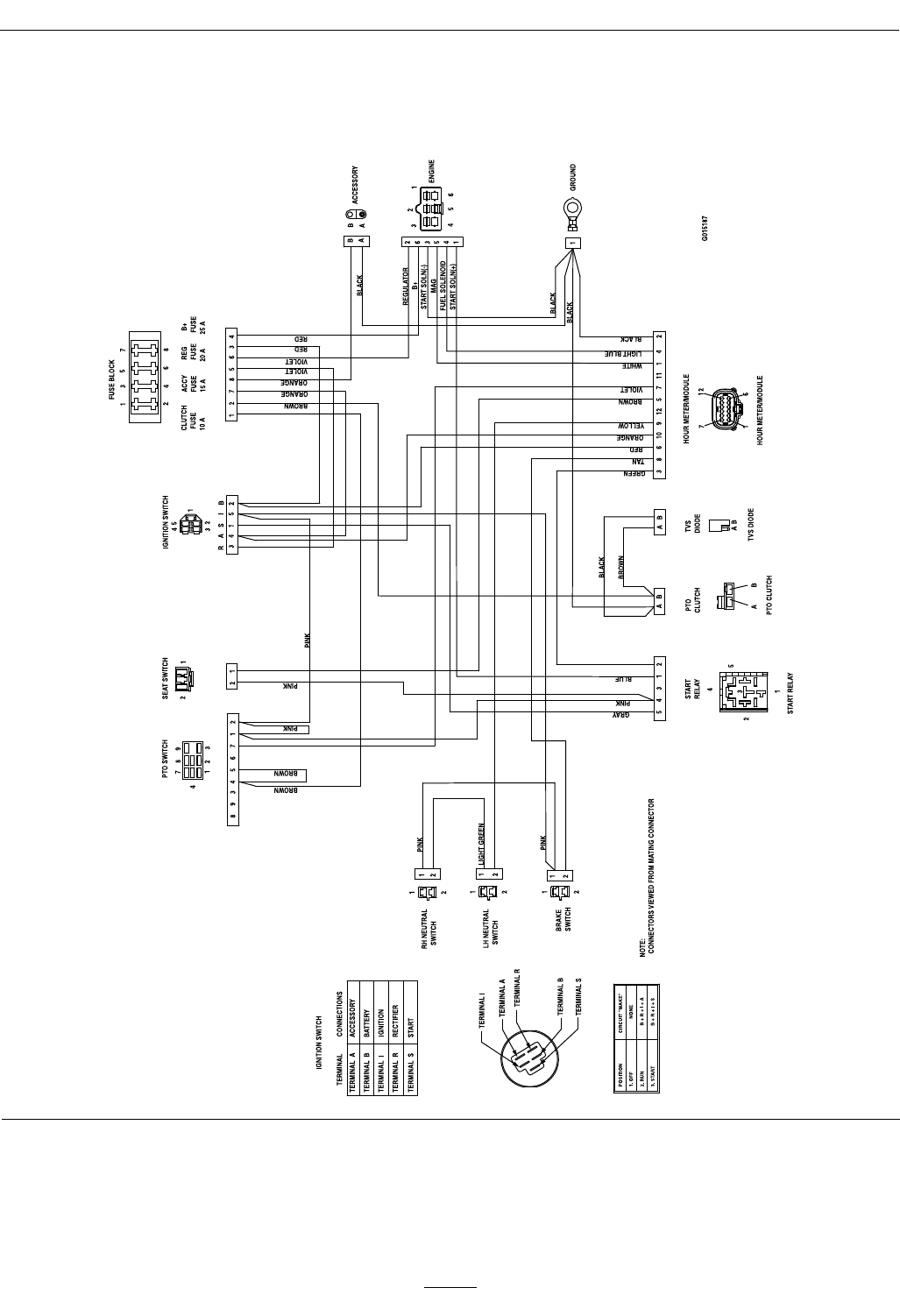
Schematics
Schematics
ElectricalDiagram
46

Schematics
ElectricalLogicSchematic
47

General Warranty Conditions and Products Covered
Exmark Mfg. Co. Inc. and its affiliate, Exmark Warranty Company,
pursuant to an agreement between them, jointly warrant on the terms and
conditions herein, that we will repair, replace or adjust any part on these
products and found by us (in the exercise of our reasonable discretion) to
be defective in factory materials or workmanship.
This warranty may only be assigned or transferred to a second (or third)
owner by an authorized Exmark dealer. The warranty period commences
upon the date of the original retail purchase.
Commercial Warranty Conditions
This warranty applies to Exmark Pioneer S-Series turf equipment sold in
the U.S. or Canada for a period of two years for commercial usage.
This warranty includes the cost of parts and labor for a period of two
years. This warranty does not cover pickup and delivery charges to and
from any authorized Exmark Service Dealer.
Consumer Warranty Conditions
This warranty applies to Exmark Pioneer S-Series turf equipment sold in
the U.S. or Canada for a period of four years or 500 hours (whichever
occurs first) for residential usage.
Residential usage means use of the product on the same lot as your home.
Use at more than one location is considered commercial use, and the
commercial use warranty detailed above would apply.
This warranty only includes the cost of parts and labor. For the first
warrantable service repair, Exmark will cover up to $45 for associated
pick-up and delivery charges to and from any authorized Exmark Service
Dealer. Additional transportation charges may apply, contact your Dealer
for details.
Warranty Exceptions
Warranty Exceptions Warranty Period
• Bags, Belts and Tires 90 days
• Battery 1 Year Prorated
• Engine *
* The Engine warranty is covered by the engine manufacturer. Please
refer to the engine manufacturer’s warranty statement that is included in
the literature packet.
Items and Conditions Not Covered
This warranty does not cover the following:
• Any damage or deterioration due to normal use, wear and tear, or
exposure.
• Cost of regular maintenance service or parts, such as filters, fuel,
lubricants, tune-up parts, and adjustments.
• Any product or part which has been altered or misused or required
replacement or repair due to normal wear, accidents, or lack of proper
maintenance.
• Any repairs necessary due to use of parts, accessories or supplies,
including gasoline, oil or lubricants, incompatible with the turf
equipment or other than as recommended in the operator's manual or
other operational instructions provided by Exmark.
There are no other express warranties except for engine and special
emission system coverage.
All warranty work must be performed by an authorized Exmark Service
Dealer using Exmark approved replacement parts.
Instructions for Obtaining Warranty Service
The product must be registered with original proof of purchase by an
Exmark Service Dealer before obtaining any warranty service.
Contact any Exmark Service Dealer to arrange service at their dealership.
To locate a dealer convenient to you, access our website at
www.exmark.com. U.S. or Canada customers may also call
402-223-6375.
If for any reason you are dissatisfied with the Service Dealer’s analysis or
with the assistance provided, contact us at:
Exmark Customer Service Department
The Exmark Warranty Company
2101 Ashland Avenue
Beatrice, NE 68310
402-223-6375 or
service@exmark.com
Owner’s Responsibilities
If your product requires warranty service it must be returned to an
authorized Exmark service dealer within the warranty period. This
warranty extends only to turf equipment operated under normal
conditions. You must read the operator’s manual. You must also properly
service and maintain your Exmark product as described in the operator’s
manual. Such routine maintenance, whether performed by a dealer or by
you, is at your expense.
General Conditions
The sole liability of Exmark and Exmark Warranty Company with respect
to this warranty shall be repair or replacement of defective components as
set forth herein. Neither Exmark nor Exmark Warranty Company
shall be liable for any incidental or consequential loss or damage.
Such damages include but are not limited to:
• Expenses related to gasoline, oil or lubricants.
• Travel time, overtime, after hours time or other extraordinary repair
charges or charges relating to repairs or replacements outside of
normal business hours at the place of business of the authorized
Exmark Service Dealer.
• Rental of like or similar replacement equipment during the period of
any warranty, repair or replacement work.
• Any telephone or telegram charges or travel charges.
• Loss or damage to person or property other than that covered by the
terms of this warranty.
• Any claims for lost revenue, lost profit or additional cost as
a result of a claim of breach of warranty.
• Attorney's fees.
No Claim of breach of warranty shall be cause for cancellation or
rescission of the contract of sale of any Exmark mower.
All implied warranties of merchantability (that the product is fit for
ordinary use) and fitness for use (that the product is fit for a
particular purpose) are limited to the duration of the express
warranty.
Some states do not allow exclusions of incidental or consequential
damages, or limitations on how long an implied warranty lasts, so the
above exclusions and limitations may not apply to you.
This warranty gives you specific legal rights, and you may also have
other rights which vary from state to state.
Pioneer S-Series Turf Equipment
2 Year Limited Commercial Warranty
4 Year or 500 Hours Limited Consumer Warranty
G4500-748_A
48

ServiceRecord
Date:DescriptionofWorkDone:ServiceDoneBy:
49

50
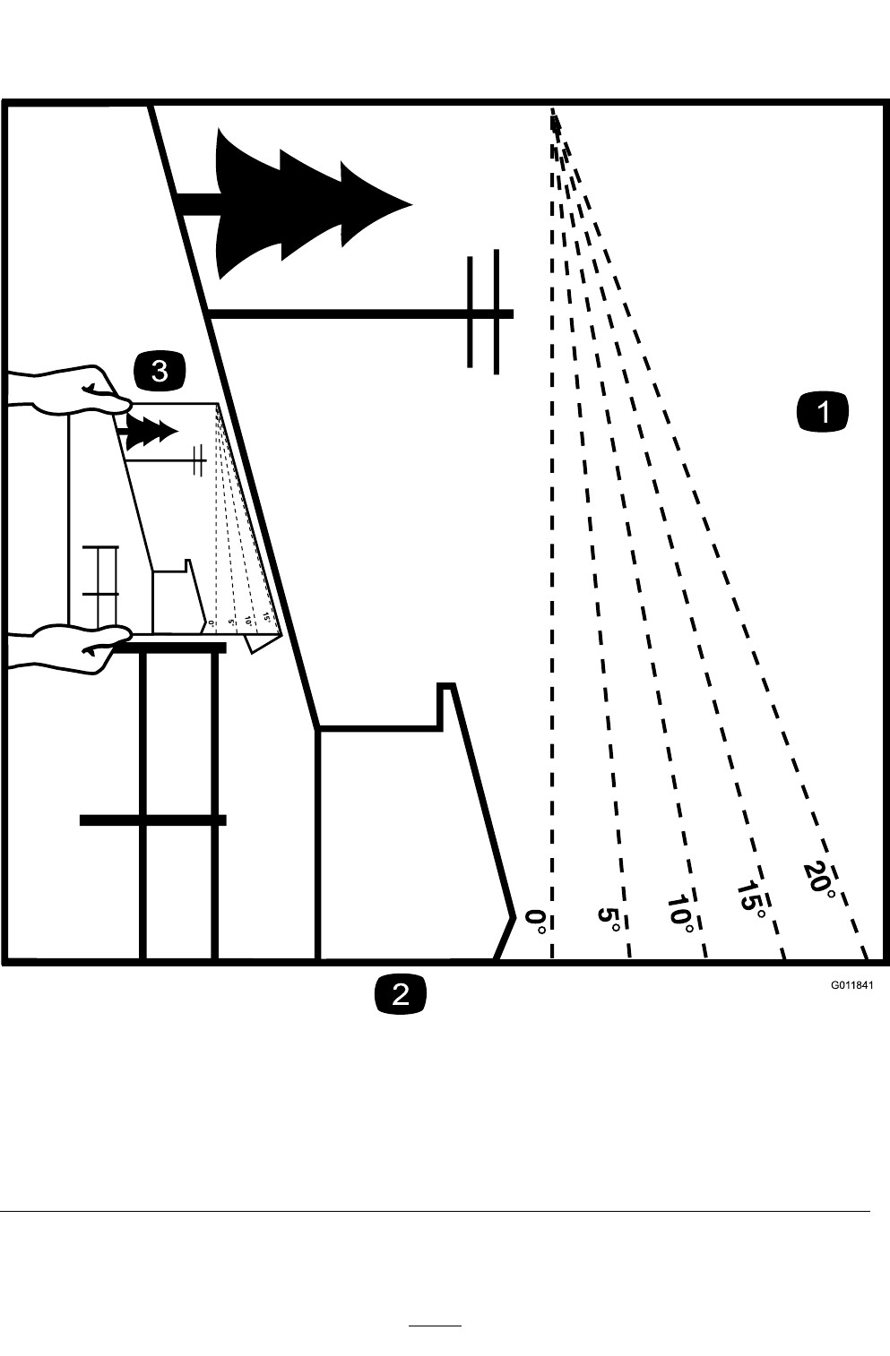
G01 1841
Figure38
Thispagemaybecopiedforpersonaluse.
1.Themaximumslopeyoucansafelyoperatethemachineonis15degrees.Usetheslopeindicatortodeterminethe
degreeofslopeofhillsbeforeoperating.DoNotoperatethismachineonaslopegreaterthan15degrees.Fold
alongtheappropriatelinetomatchtherecommendedslope.
2.Alignthisedgewithaverticalsurface,atree,building,fencepole,etc.
3.Exampleofhowtocompareslopewithfoldededge.
51

MID-MOUNT RIDING ACCESSORIES AND OPTIONS
SEE EXMARK’S COMPLETE LINE OF ACCESSORIES AND OPTIONS
WALK-BEHIND ACCESSORIES AND OPTIONS
GRASS CATCHER
MICRO-MULCH SYSTEM
TURF STRIPER
STANDON
CUSTOM RIDE SEAT SUSPENSION SYSTEM
FULL SUSPENSION SEAT
DECK LIFT ASSIST KIT
HITCH KIT
LIGHT KIT
12V POWER PORT
MICRO-MULCH SYSTEM
OPERATOR CONTROLLED DISCHARGE
ROLL OVER PROTECTION SYSTEM (ROPS)
SUN SHADE
TRASH CONTAINER
TURF STRIPER
ULTRA VAC COLLECTION SYSTEM
ULTRA VAC QUICK DISPOSAL SYSTEM
OUT-FRONT RIDING ACCESSORIES AND OPTIONS
CUSTOM RIDE SEAT SUSPENSION SYSTEM
DUAL-TAIL WHEEL
FLOOR PAN EXTENDER
HITCH KIT
LIGHT KIT
MICRO-MULCH SYSTEM
ROLL OVER PROTECTION SYSTEM (ROPS)
SNOW BLADE
SNOWBLOWER
SUN SHADE
TRASH CONTAINER
ULTRA VAC COLLECTION SYSTEM
ULTRA VAC QUICK DISPOSAL SYSTEM
WEATHER CAB
PlaceModelNo.andSerialNo.
LabelHere(IncludedintheLiterature
Pack)orFillinBelow
DatePurchased
EngineModelNo.andSpec.No.
ModelNo.EngineSerialNo.(E/No)
SerialNo.
©2011ExmarkMfg.Co.,Inc.
IndustrialParkBox808
Beatrice,NE68310
AllRightsReserved
PartNo.4501-000Rev.A
(402)223-6300
Fax(402)223-5489
PrintedintheUSA
www.exmark.com
