Exmark Quest Lawn Mower Users Manual
Lawn Mower to the manual 5377fd67-82c9-414a-8091-3075a47b8941
2015-02-04
: Exmark Exmark-Quest-Lawn-Mower-Users-Manual-367010 exmark-quest-lawn-mower-users-manual-367010 exmark pdf
Open the PDF directly: View PDF ![]() .
.
Page Count: 56

QUEST®
ForSerialNos.
720,000&Higher
PartNo.4500-338Rev.A

WARNING
CALIFORNIA
Proposition65Warning
Theengineexhaustfromthisproduct
containschemicalsknowntotheStateof
Californiatocausecancer,birthdefects,or
otherreproductiveharm.
Important:Thisengineisnotequippedwith
asparkarrestermufer.Itisaviolationof
CaliforniaPublicResourceCodeSection4442to
useoroperatetheengineonanyforest-covered,
brush-covered,orgrass-coveredland.Other
statesorfederalareasmayhavesimilarlaws.
ThissparkignitionsystemcomplieswithCanadian
ICES-002,ISO14982,EN55012.
TheenclosedEngineOwner’sManualis
suppliedforinformationregardingtheUS
EnvironmentalProtectionAgency(EPA)and
theCaliforniaEmissionControlRegulationof
emissionsystems,maintenance,andwarranty.
Replacementsmaybeorderedthroughthe
enginemanufacturer.
Formodelswithstatedenginehorsepower,thegross
horsepoweroftheenginewaslaboratoryratedbythe
enginemanufacturerinaccordancewithSAEJ1940.
Asconguredtomeetsafety,emission,andoperating
requirements,theactualenginehorsepoweronthis
classoflawnmowerwillbesignicantlylower.
©2007–2008—ExmarkMfg.Co.,Inc.
IndustrialParkBox808
Beatrice,NE683102
Contactusatwww.Exmark.com.
PrintedintheUSA.
AllRightsReserved
Introduction
Readthisinformationcarefullytolearnhowto
operateandmaintainyourproductproperlyandto
avoidinjuryandproductdamage.Youareresponsible
foroperatingtheproductproperlyandsafely.
YoumaycontactExmarkdirectlyat
www.Exmark.comforproductandaccessory
informationorhelpndingadealer.
Wheneveryouneedservice,genuineExmarkparts,
oradditionalinformation,contactanAuthorized
ServiceDealerorExmarkCustomerServiceandhave
themodelandserialnumbersofyourproductready.
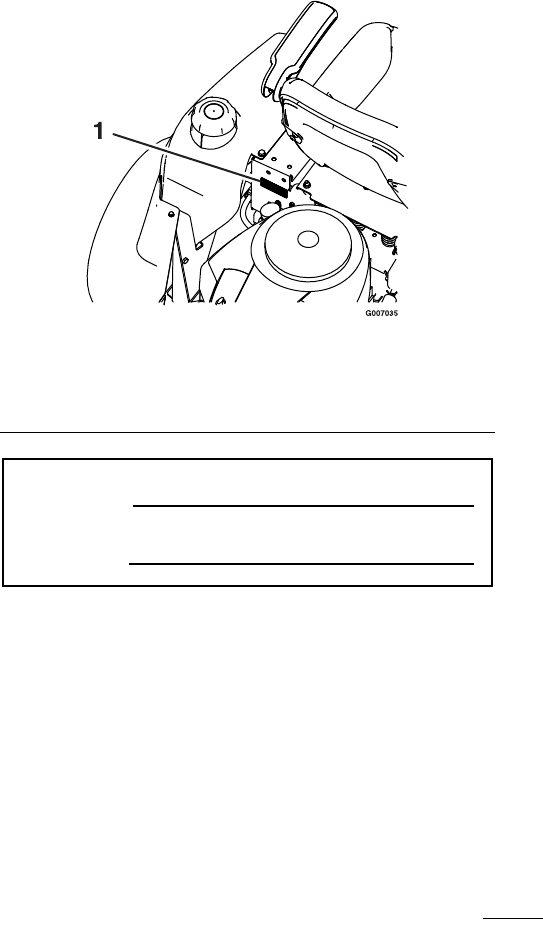
Figure1identiesthelocationofthemodelandserial
numbersontheproduct.Writethenumbersinthe
spaceprovided.
Figure1
Behindtheseat
1.Modelandserialnumberlocation
ModelNo.
SerialNo.
3

Contents
Introduction...........................................................3
Safety.....................................................................5
SafetyAlertSymbol.........................................5
SafeOperatingPractices..................................5
SafetyandInstructionalDecals.......................8
Specications.......................................................13
ModelNumbers............................................13
Systems.........................................................13
Dimensions...................................................14
TorqueRequirements....................................15
ProductOverview................................................15
Operation.............................................................16
Controls........................................................16
OperatingInstructions..................................17
RecommendedGasoline................................18
CheckingtheEngineOilLevel.......................19
StartingtheEngine........................................19
OperatingtheBlades.....................................20
StoppingtheEngine......................................21
TheSafetyInterlockSystem...........................21
DrivingForwardorBackward........................22
StoppingtheMachine....................................23
TrackingAdjustment.....................................23
AdjustingtheHeightofCut...........................23
AdjustingtheAnti-ScalpRollers.....................24
PositioningtheSeat.......................................24
ChangingtheSeatRideSuspension................24
AdjustingtheMotionControlLevers.............25
PushingtheMachinebyHand........................25
SideDischarge...............................................26
Transporting.................................................26
OperatingTips.............................................27
Maintenance.........................................................29
RecommendedMaintenanceSchedule(s)...........29
PremaintenanceProcedures..............................30
RaisingtheSeat.............................................30
AccessingtheBattery....................................30
PeriodicMaintenance.......................................30
Lubrication....................................................30
EngineMaintenance......................................31
ServicingtheEngineOil................................32
CheckingtheHydraulicOilLevel...................34
ChangetheHydraulicSystemFilter................34
ServicingtheSparkPlug................................35
CleaningtheBlowerHousing.........................35
FuelSystemMaintenance..............................36
ElectricalSystemMaintenance.......................36
ChargingtheBattery......................................37
ServicingtheFusesandRelay.........................38
DriveSystemMaintenance............................39
CheckingtheTirePressure............................39
MowerMaintenance......................................39
ServicingtheCuttingBlades..........................39
MowerBeltMaintenance...............................41
LevelingtheMowerDeck..............................42
AdjustingtheBladeSlope..............................42
RemovingtheMowerDeck...........................44
InstallingtheMowerDeck.............................44
ReplacingtheDischargeDeector.................45
Cleaning...........................................................46
WashingtheUndersideoftheMower.............46
Storage.................................................................47
CleaningandStorage.....................................47
Troubleshooting...................................................48
Schematics...........................................................50
4

Safety
Safety
SafetyAlertSymbol
Thismanualidentiespotentialhazardsandhas
safetymessagesidentiedbythesafetyalertsymbol
(Figure2),whichsignalsahazardthatmaycause
seriousinjuryordeathifyoudonotfollowthe
recommendedprecautions.
Figure2
1.Safetyalertsymbol
Thismanualusestwootherwordstohighlight
information.Importantcallsattentiontospecial
mechanicalinformationandNoteemphasizes
generalinformationworthyofspecialattention.
Thismachinemeetsorexceedsthesafety
specicationsoftheAmericanNational
StandardsInstituteB71.1-2003ineffectatthe
timeofproduction.However,improperuse
ormaintenancebytheoperatororownercan
resultininjury.Toreducethepotentialfor
injury,complywiththesesafetyinstructions
andalwayspayattentiontothesafetyalert
symbol,whichmeansCAUTION,WARNING,
orDANGER-"personalsafetyinstruction."
Failuretocomplywiththeinstructionmayresult
inpersonalinjuryordeath.
SafeOperatingPractices
ThefollowinginstructionsarefromANSIstandard
B71.1-2003.
Thisproductiscapableofamputatinghandsand
feetandthrowingobjects.Alwaysfollowallsafety
instructionstoavoidseriousinjuryordeath.
GeneralOperation
•Read,understand,andfollowallinstructionsin
theoperator’smanualandonthemachinebefore
starting.
•DoNotplacehandsorfeetnearrotatingpartsor
underthemachine.Keepclearofthedischarge
openingatalltimes.
•Allowonlyresponsibleadultswhoarefamiliar
withtheinstructionstooperatethemachine.
•Cleartheareaofobjectssuchasrocks,toys,wire,
etc.,whichcouldbepickedupandthrownbythe
blade.
•Besuretheareaisclearofotherpeoplebefore
mowing.Stopthemachineifanyoneentersthe
area.
•Nevercarrypassengers.
•DoNotmowinreverseunlessabsolutely
necessary.Alwayslookdownandbehindbefore
andwhilebackingup.
•Beawareofthemowerdischargedirectionand
DoNotpointitatanyone.Avoiddischarging
materialagainstawallorobstruction.Material
mayricochetbacktowardtheoperator.Stopthe
bladeswhencrossinggravelsurfaces.
•DoNotoperatethemowerwithouteitherthe
entiregrasscollectionsystemorthedischarge
deectorinplace.
•Bealert,slowdownandusecautionwhenmaking
turns.Lookbehindandtothesidebefore
changingdirections.
•Neverleavearunningmachineunattended.
Alwaysturnoffblades,engageparkingbrake,
stopengine,andremovekeybeforedismounting.
•Turnoffbladeswhennotmowing.Stopthe
engine,waitforallpartstocometoacomplete
stop,engageparkingbrake,andremovekey
beforecleaningthemachine,removingthegrass
oruncloggingthedeector.
•Operatethemachineonlyindaylightorgood
articiallight.
•DoNotoperatethemachinewhileunderthe
inuenceofalcoholordrugs.
•Watchfortrafcwhenoperatingnearorcrossing
roadways.
•Useextracarewhenloadingorunloadingthe
machineintoatrailerortruck
•Alwaysweareyeprotectionwhenoperatingthe
mower.
•Dataindicatesthatoperators,age60yearsand
above,areinvolvedinalargepercentageofriding
mower-relatedinjuries.Theseoperatorsshould
evaluatetheirabilitytooperatetheridingmower
5

Safety
safelyenoughtoprotectthemselvesandothers
fromseriousinjury.
•Alwaysfollowtherecommendationsforwheel
weightsorcounterweights.
SlopeOperation
Slopesareamajorfactorrelatedtolossofcontrol
andtip-overaccidents,whichcanresultinsevere
injuryordeath.Operationonallslopesrequiresextra
caution.Ifyoucannotbackuptheslopeorifyou
feeluneasyonit,DoNotmowit.
•DoNotmowslopesgreaterthan15degrees.
•Watchforditches,holes,rocks,dips,andrisesthat
changetheoperatingangle,asroughterraincould
overturnthemachine.
•Choosealowgroundspeedsoyouwillnothave
tostopwhileoperatingonaslope.
•DoNotmowslopeswhengrassiswet.Slippery
conditionsreducetractionandcouldcausesliding
andlossofcontrol.
•Reducespeedanduseextremecautiononslopes.
•DoNotmakesuddenturnsorrapidspeed
changes.
•Removeormarkobstaclessuchasrocks,tree
limbs,etc.fromthemowingarea.Tallgrasscan
hideobstacles.
•Avoidsuddenstartswhenmowinguphillbecause
themowermaytipbackwards.
•Beawarethatlossoftractionmayoccurgoing
downhill.Weighttransfertothefrontwheels
maycausedrivewheelstoslipandcauselossof
brakingandsteering.
•Alwaysavoidsuddenstartingorstoppingona
slope.Iftireslosetraction,disengagetheblades
andproceedslowlyofftheslope.
•Useextremecarewithgrasscollectionsystemsor
otherattachments.Thesecanchangethestability
ofthemachineandcauselossofcontrol.
•DoNottrytostabilizethemachinebyputting
yourfootontheground.
•DoNotmowneardrop-offs,ditches,steepbanks
orwater.Wheelsdroppingoveredgescancause
rollovers,whichmayresultinseriousinjury,death
ordrowning.
•Useawalkbehindmowerand/orahandtrimmer
neardrop-offs,ditches,steepbanksorwater.
Children
Tragicaccidentscanoccuriftheoperatorisnot
alerttothepresenceofchildren.Childrenareoften
attractedtothemachineandthemowingactivity.
Neverassumethatchildrenwillremainwhereyou
lastsawthem.
•Keepchildrenoutofthemowingareaandunder
thewatchfulcareofanotherresponsibleadult,
nottheoperator.
•Bealertandturnthemachineoffifchildrenenter
thearea.
•Beforeandwhilebackingorchangingdirection,
lookbehind,down,andside-to-sideforsmall
children.
•Nevercarrychildren,evenwiththebladesoff.
Theymayfalloffandbeseriouslyinjuredor
interferewithsafemachineoperation.
•Childrenwhohavebeengivenridesinthepast
maysuddenlyappearinthemowingareafor
anotherrideandberunoverorbackedoverby
themower.
•Neverallowchildrentooperatethemachine.
•Useextracarewhenapproachingblindcorners,
shrubs,trees,theendofafenceorotherobjects
thatmayobscurevision.
Towing
•UsefortowingonlyifequippedwithanExmark
hitchkit.DoNotattachtowedequipmentexcept
atthehitchpoint.
•FollowExmark’srecommendationforweight
limitsfortowedequipmentandtowingonslopes.
Thisinformationcanbefoundinthehitchkit
instructionsheetandonthedecal.
•Neverallowchildrenorothersinorontowed
equipment.
•Onslopes,theweightofthetowedequipment
maycauselossoftractionandlossofcontrol.
•Travelslowlyandallowextradistancetostop.
Service
SafeHandlingofGasoline
Toavoidpersonalinjuryorpropertydamage,use
extracarewhenhandlinggasolineandotherfuels.
Theyareammableandthevaporsareexplosive.
6

Safety
•Extinguishallcigarettes,cigars,pipesandother
sourcesofignition.
•Useonlyanapprovedcontainer.
•Neverremovethegascaporaddfuelwhenthe
engineisrunning.Allowtheenginetocoolbefore
refueling.
•Neverrefuelthemachineindoors.
•Neverstorethemachineorfuelcontainerinside
wherethereisanopename,suchasnearawater
heaterorfurnace.
•Neverllcontainersinsideavehicleorona
truckortrailerwithaplasticliner.Alwaysplace
containersonthegroundawayfromyourvehicle
beforelling.
•Removegas-poweredequipmentfromthetruck
ortrailerandrefuelitontheground.Ifthisis
notpossible,thenrefuelsuchequipmentwitha
portablecontainer,ratherthanfromagasoline
dispensernozzle.
•Keepthenozzleincontactwiththerimofthe
fueltankorcontaineropeningatalltimesuntil
thefuelingiscomplete.DoNotuseanozzle
lock-opendevice.
•Iffuelisspilledonclothing,changeclothing
immediately.
•Neveroverllthefueltank.Replacegascapand
tightensecurely.
GeneralService:
•Neverrunamachineinsideaclosedarea.
•Keepnutsandboltstight,especiallytheblade
attachmentbolts.Keepequipmentingood
condition.
•Nevertamperwithsafetydevices.Checktheir
properoperationregularly.
•Keepthemachinefreeofgrass,leaves,orother
debrisbuild-up.Cleanupoilorfuelspillageand
fuelsoakeddebris.Allowthemachinetocool
beforestoring.
•Stopandinspecttheequipmentifyoustrikean
object.Repair,ifnecessary,beforerestarting.
•Nevermakeanyadjustmentsorrepairswiththe
enginerunning.
•Grasscollectionsystemcomponentsaresubject
towear,damageanddeterioration,whichcould
exposemovingpartsorallowobjectstobe
thrown.Frequentlycheckcomponentsand
replacewithmanufacturers’recommendedparts,
whennecessary.
•Mowerbladesaresharpandcancut.Wrapthe
bladesorweargloves,anduseextracautionwhen
servicingthem.
•Checkforproperbrakeoperationfrequently.
Adjustandserviceasrequired.
•Maintainorreplacesafetyandinstructiondecals
asnecessary.
•UseonlygenuineExmarkreplacementpartsto
ensurethatoriginalstandardsaremaintained.
ExmarkRidingMowerSafety
Thefollowinglistcontainssafetyinformationspecic
toExmarkproductsorothersafetyinformationthat
youmustknowthatisnotincludedintheANSI
standards.
•Engineexhaustcontainscarbonmonoxide,which
isanodorless,deadlypoisonthatcankillyou.Do
Notrunengineindoorsorinanenclosedarea.
•Stoptheengine,waitforallmovingpartstostop,
engageparkingbrake,disconnectsparkplug
wire(s)andremovekeybeforeperformingany
service,repairs,maintenanceoradjustments.
•Keephands,feet,hair,andlooseclothingaway
fromattachmentdischargearea,undersideof
mowerandanymovingpartswhileengineis
running.
•DoNottouchequipmentorattachmentparts
whichmaybehotfromoperation.Allowtocool
beforeattemptingtomaintain,adjustorservice.
•Batteryacidispoisonousandcancauseburns.
Avoidcontactwithskin,eyes,andclothing.
Protectyourface,eyes,andclothingwhen
workingwithabattery.
•Batterygasescanexplode.Keepcigarettes,sparks
andamesawayfrombattery.
•UseonlyExmarkapprovedattachments.
Warrantymaybevoidedifusedwithunapproved
attachments.
•Ifloadingthemachineontoatrailerortruck,use
asingle,full-widthramponly.Therampangle
shouldnotexceed15degrees.
Note:Theleftandrightsidesofthemachineare
determinedwhilesittingintheseatinthenormal
operatingposition
7
Safety
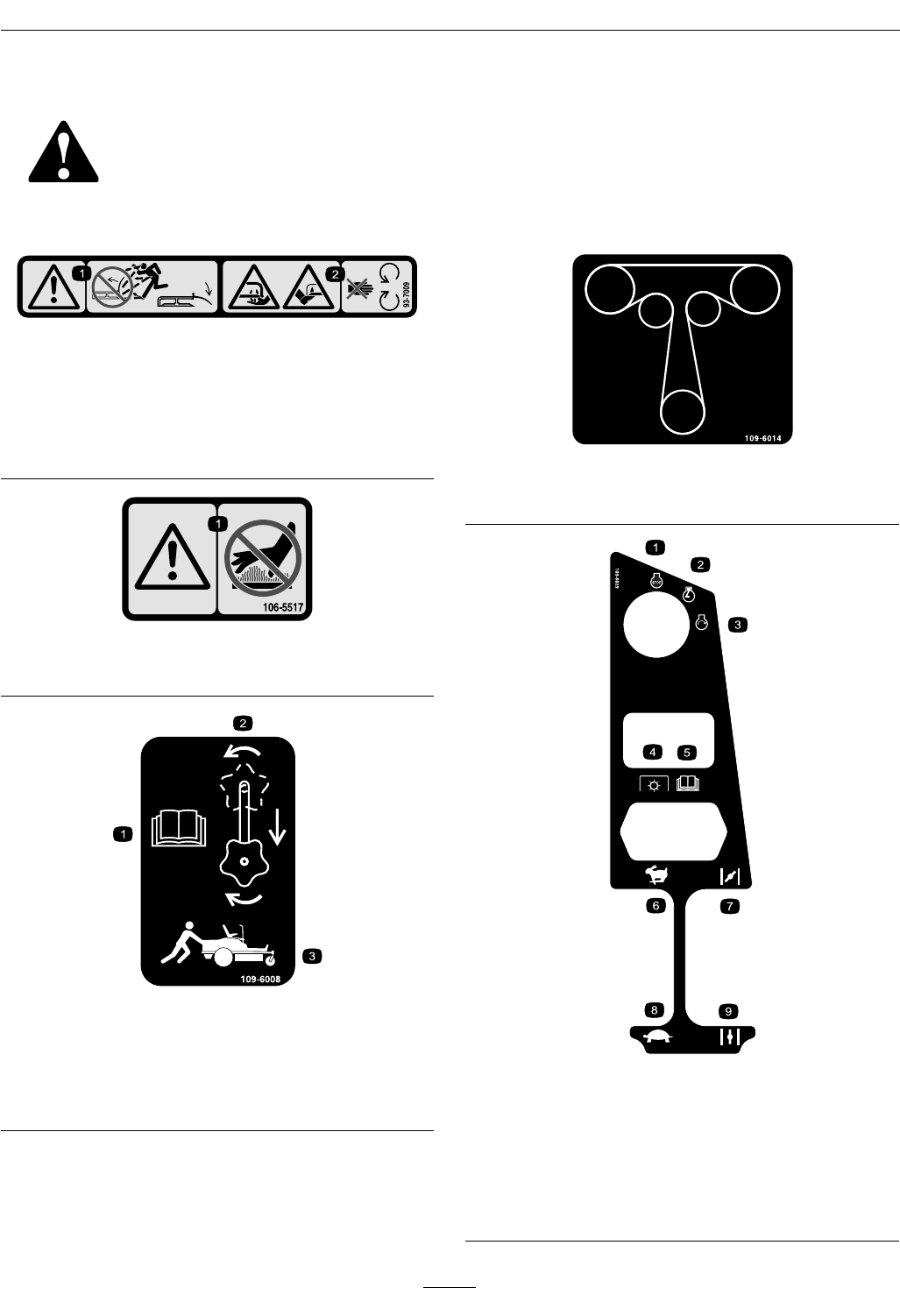
SafetyandInstructionalDecals
Safetydecalsandinstructionsareeasilyvisibletotheoperatorandarelocatednearanyarea
ofpotentialdanger.Replaceanydecalthatisdamagedorlost.
93-7009
1.Warning–DoNotoperate
themowerwiththe
dischargedeectorup
orremoved;keepthe
dischargedeectorin
place.
2.Cutting/dismemberment
hazardofhandorfoot,
mowerblade–stayaway
frommovingparts.
106-5517
1.Warning–DoNottouchthehotsurface.
109-6008
1.ReadtheOperator’s
Manual.
3.Pushthemachine.
2.Rotatethedriverelease
knobtoloosen,slidethe
knob,andtighten.
109-6014
TractionDriveBeltRouting
109-6029
1.Engine–stop6.Throttle–fast
2.Engine–run7.Choke–on
3.Engine–start8.Throttle–slow
4.Powertake-off(PTO),
Bladecontrolswitch
9.Choke–off
5.ReadtheOperator’s
Manual.
8
Safety
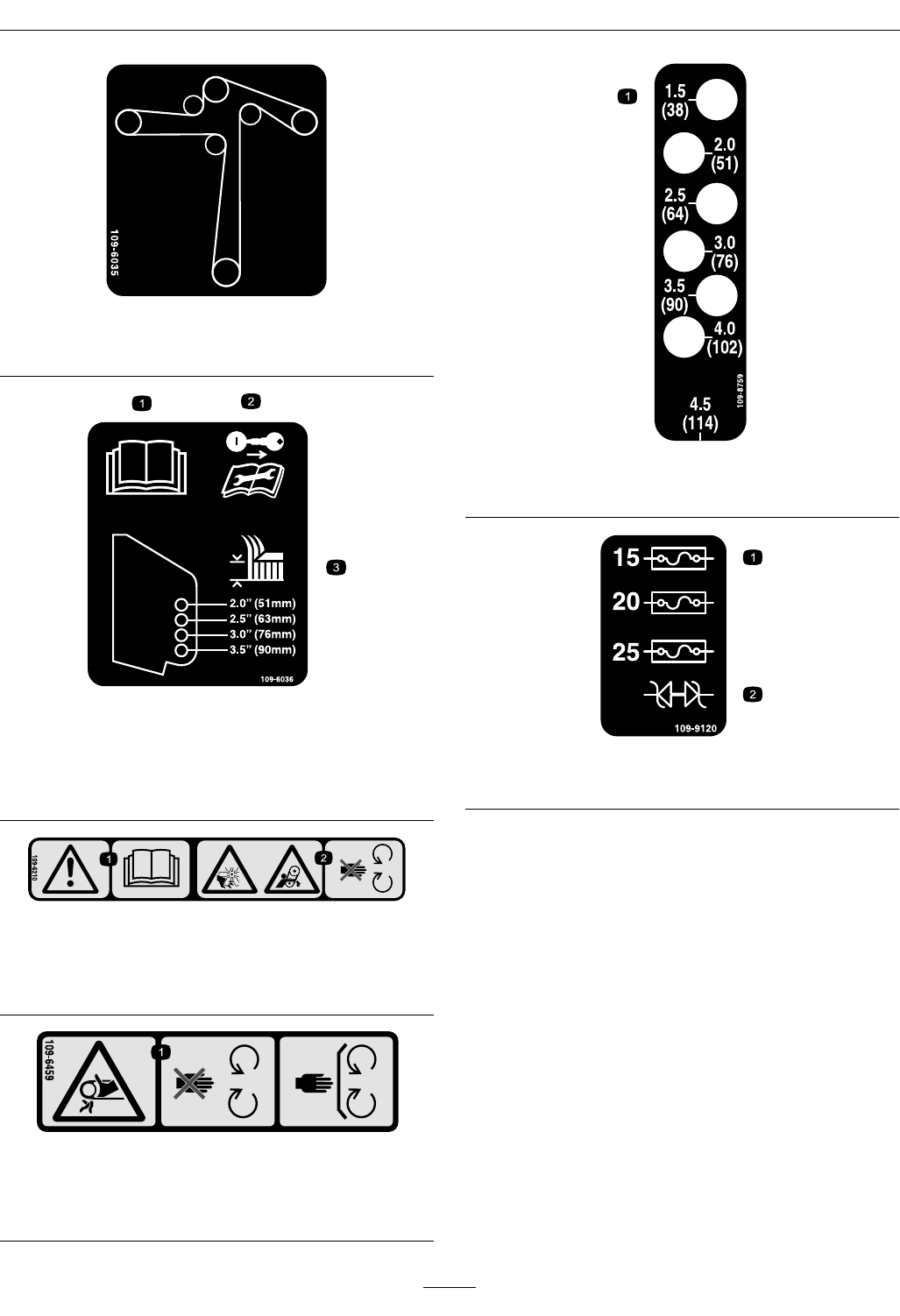
109-6035
DeckDriveBeltRouting
109-6036
1.ReadtheOperator’sManual.
2.Removetheignitionkeyandreadtheinstructionsbefore
servicingorperformingmaintenance.
3.Heightofcut.
109-6210
1.ReadtheOperator’sManual.
2.Cutting/dismembermenthazard,fanandentanglement
hazard,belt–stayawayfrommovingparts.
109-6459
1.Entanglementhazard,belt—DoNotopenorremove
safetyshieldswhileengineisrunning,keepshieldsin
place.
109-8759
1.Heightofcut
109-9120
1.Fuse2.Diode
9
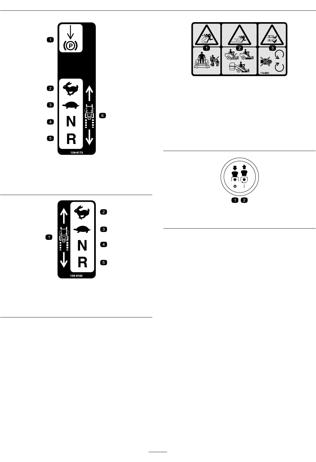
Safety
109-9173
1.Parkingbrake4.Neutral
2.Fast5.Reverse
3.Slow6.MachineSpeed
109-9182
1.Machinespeed4.Neutral
2.Fast5.Reverse
3.Slow
110-6691
1.Thrownobjects
hazard–keepbystanders
asafedistancefromthe
machine.
3.Cutting/dismemberment
ofhandorfoot–stay
awayfrommovingparts.
2.Thrownobjectshazard,
mower–keepthe
dischargedeector
orcollectionsystemin
place.
PTOSymbols
1.PTO—Off2.PTO—On
10
Safety
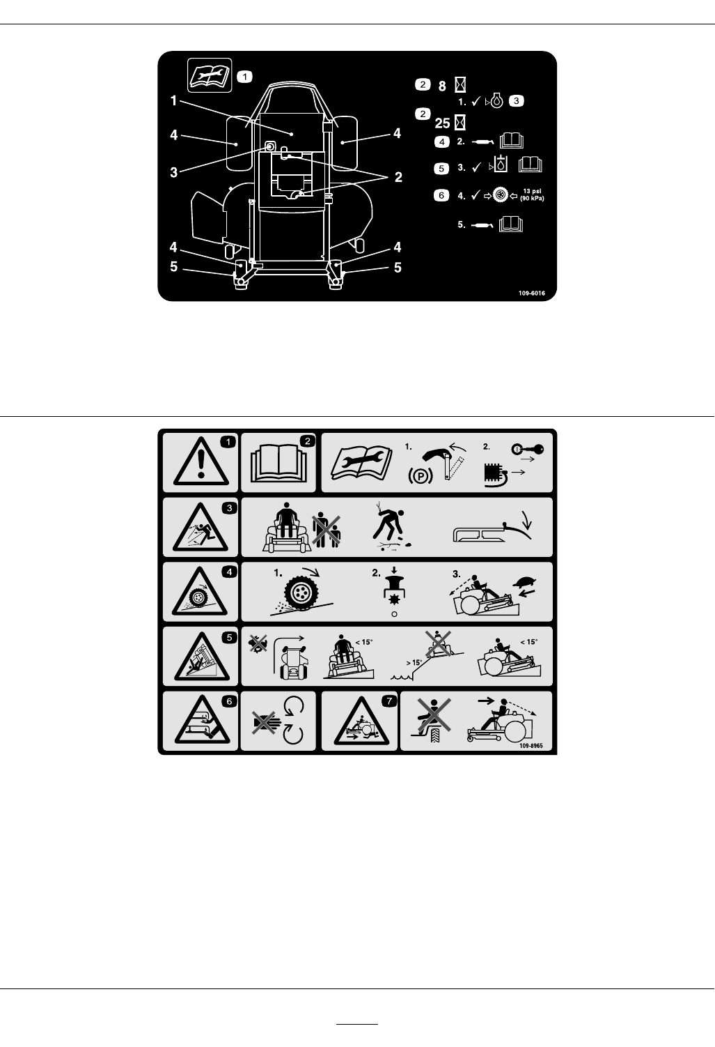
109-6016
1.Readtheinstructionsbeforeservicingorperforming
maintenance.
4.RefertotheOperator’smanualforgreaseinstructions.
2.Timeinterval5.CheckhydraulicoillevelandrefertotheOperator’s
Manualforfurtherinstructions.
3.Checkoillevel.6.Checktirepressure.
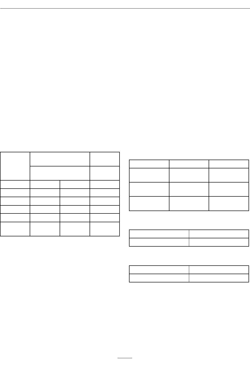
109-8965
1.Warning–readtheOperator’sManual.5.Tippinghazard–avoidsuddenandsharpturnswhileon
slopes,onlymowacrossslopeslessthan15degrees,
keepasafedistancefromwater,andonlymowupand
downslopeslessthan15degrees.
2.Readtheinstructionsbeforeservicingorperforming
maintenance;applyparkingbrake,removetheignitionkey
anddisconnectthesparkplugwire.
6.Cutting/dismembermenthazardofhandorfoot,mower
blade–stayawayfrommovingparts.
3.Thrownobjecthazard—keepbystandersasafedistance
fromthemachine,pickupdebrisbeforeoperating,keep
thedischargedeectorinplace.
7.Crushing/dismembermenthazardofbystanders,
reversing–DoNotcarrypassengers,lookbehindand
downwhenreversing.
4.Lossoftraction/controlhazard,slopes–lossof
traction/controlonslope,disengagethebladecontrol
switch(PTO),proceedofftheslopeslowly.
11

Safety
BatterySymbols
Someorallofthesesymbolsareonyourbattery.
1.Explosionhazard5.ReadtheOperator’sManual.9.Flusheyesimmediatelywithwater
andgetmedicalhelpfast.
2.Nore,openames,orsmoking6.Keepbystandersasafedistance
fromthebattery.
10.Containslead;donotdiscard.
3.Causticliquid/chemicalburnhazard7.Weareyeprotection;explosive
gasescancauseblindnessand
otherinjuries.
4.Weareyeprotection8.Batteryacidcancauseblindnessor
severeburns.
12

Specications
Specications
ModelNumbers
SerialNos:720,000andHigher
QST22BE482;QST23KC482;QST23KC522;QST24BE522
Systems
Engine
•EngineSpecications:SeeyourEngineOwner’s
Manual
•RPM:
Briggs&Stratton:FullSpeed:3650±100(max)
RPM(NoLoad)Idle:1650(min)RPM
KohlerCommand:FullSpeed:3600±75(max)
RPM(NoLoad)Idle:1750(min)RPM
FuelSystem
•Capacity:4.0gal.(15.1L)
•TypeofFuel:Regularunleadedgasoline,87
octaneorhigher.
•FuelFilter:
Briggs&Stratton:Briggs&StrattonP/N695666
KohlerCommand:KohlerP/N2405010
•FuelShut-OffValve:1/4turnincrements(“ON”,
“OFF”)
ElectricalSystem
•ChargingSystem:FlywheelAlternator
•ChargingCapacity:
Briggs&Stratton:16amps
KohlerCommand:15amps
•BatteryType:BCIGroupU1
•BatteryVoltage:12Volt
•Polarity:NegativeGround
•Fuses:One25amp,one20amp;one15amp
bladetype
•Diode:TVS
SafetyInterlockSystem
•PTOmustbedisengaged,brakeengaged,and
motioncontrolleversout(neutrallock)tostart
engine.(Itisnotnecessaryfortheoperatortobe
intheseattostarttheengine.)
•OperatormustbeinseatwhenPTOisengaged,
brakeisdisengaged,ormotioncontrolleversare
movedinorenginewillstop.
•Enginewillstopifeithertheleft,theright,or
bothleversaremovedfromneutrallockposition
whilebrakeisengaged.
OperatorControls
•SteeringandMotionControl:
Note:Motioncontrolleversareadjustableto
twoheights.
–Separatelevers,oneachsideoftheconsole,
controlspeedanddirectionoftravelofthe
respectivedrivewheels.
–Steeringiscontrolledbyvaryingtheposition
oftheleversrelativetoeachother.
–Movingmotioncontrolleversoutward(in
slots)locksthedrivesysteminneutral.
•PTOEngagementSwitch:Engageselectricclutch
(todrivebelt)whichengagesmowerblades.
•ParkingBrakeLever:Engagesparkingbrake.
•DeckHeightAdjustmentPin:Setscuttingheight
todesiredposition.
•DeckLiftAssistLever:Footpedalthatassists
inraisingthedeck.
Seat
•Type:Standardseatwithhighback,foampadded
withspringsuspensionandarmrests.
•Mounting:Hingedtotiltupforaccessto
hydraulicpumps,batteryandothercomponents.
Heldintiltedpositionwithlanyard.Adjustable
foreandaftseattrack.
13
Specications
•Armrests:Standard–foampaddedip-up
adjustableheightarmrests.
•SeatSafetySwitch:IncorporatedintotheSafety
InterlockSystem.
HydrostaticGroundDriveSystem
•HydrostaticPumps:TwoHydroGearZT2800
Integrateddrivesystems.
•HydraulicOilType:UseMobil115W-50
Syntheticmotoroil.
•Speeds:
–0-7.0mph(11.3km/hr)forward.
–0-5.0mph(8.0km/hr)reverse.
•Drivewheelreleases,locatedonleftandright
sidesofenginedeck,allowmachinetobemoved
whentheengineisnotrunningandbrakeisoff.
Tires&Wheels
DriveFront
Caster
Pneumatic(Air-Filled)Pneumatic
(Air-Filled)
DeckSize4852AllDecks
Quantity222
TreadTurfTecTurfTecSmooth
Size20x8.00-820x10.00-810x4
PlyRating44
Pressure13psi
(90kPa)
13psi
(90kPa)
13psi
(90kPa)
CuttingDeck
•CuttingWidth:
–48inchDeck:48inches(122cm)
–52inchDeck:52inches(132cm)
•Discharge:Side
•BladeSize:(3ea.)
–48inchDeck:16.25inches(41.3cm)
–52inchDeck:18.00inches(45.7cm)
•BladeSpindles:Solidsteelspindleswithno
maintenancebearings.
•DeckDrive:Electricclutchmountedonvertical
engineshaft.Bladesaredrivenbyonebelt
(w/self-tensioningidler)directfromtheengine.
•Deck:Fulloatingdeckisattachedtoout-front
supportframe.Maximumturfprotectionis
providedwiththreeanti-scalprollers(bothdeck
sizes).
Deckdesignallowsforbagging,mulchingorside
discharge.
•DeckDepth:
–48inchDeck:5.0inches(12.7cm)
–52inchDeck:5.0inches(12.7cm)
•CuttingHeightAdjustment:Afootdeckliftlever
isusedtoadjustthecuttingheightfrom11/2
inch(3.8cm)to41/2inches(11.4cm)in1/2
inch(1.3cm)increments.
•MulchingKit:Optional.
Dimensions
OverallWidth:
48inchDeck52inchDeck
WithoutDeck45.5inches
(116cm)
47.0inches
(119cm)
DeectorUp48.3inches
(122cm)
53.0inches
(135cm)
DeectorDown59.4inches
(151cm)
64.2inches
(163cm)
OverallLength:
48inchDeck52inchDeck
73.4inches(186cm)73.4inches(186cm)
OverallHeight:
48inchDeck52inchDeck
41.8inches(106cm)41.8inches(106cm)
14
ProductOverview
TreadWidth:(CentertoCenterof
Tires,Widthwise)
48inchDeck52inchDeck
DriveWheels36.0inches
(91cm)
36.8inches
(93cm)
CasterWheels33.5inches
(85cm)
33.5inches
(85cm)
WheelBase:(CenterofCasterTireto
CenterofDriveTire)
48inchDeck52inchDeck
48.9inches(124cm)48.9inches(124cm)
CurbWeight:
48inchDeck52inchDeck
645lb(293kg)660lb(299kg)
TorqueRequirements
BoltLocationTorque
SpindlePulleyNut95-105ft-lb(129-142N-m)
BladeMountingBolt
(lubricatewithanti-seize)
32-42ft-lb(43-57N-m)
EngineMountingBolts27-33ft-lb(37-45N-m)
Anti-ScalpRollerNyloc
Nut
27-33ft-lb(37-45N-m)
WheelLugNuts70-90ft-lb(95-122N-m)
ClutchMountingBolt
(securedwiththreadlocker)
50-55ft-lb(68-75N-m)
SparkPlug15ft-lb(20N-m)
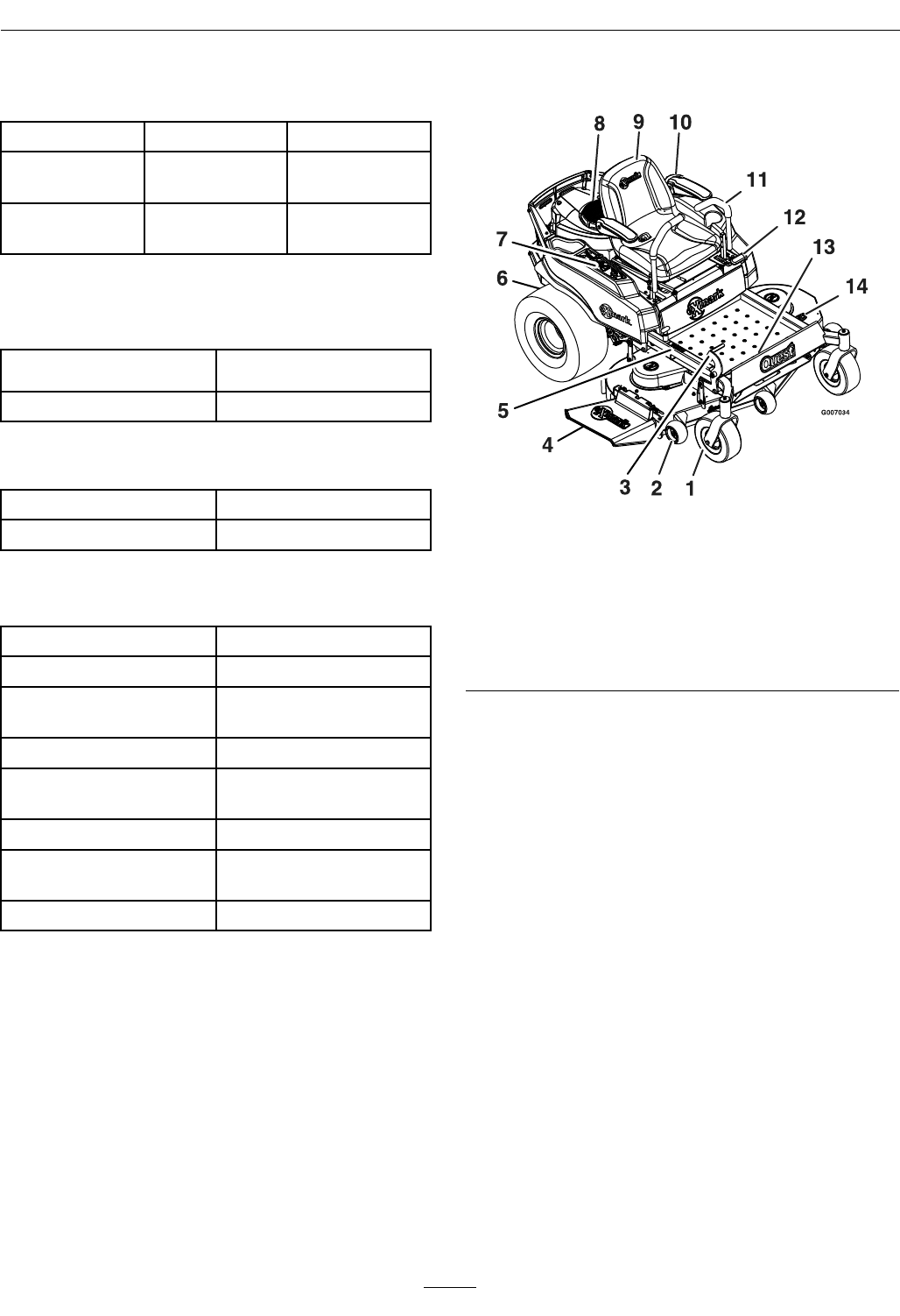
ProductOverview
Figure3
1.Frontcasterwheel8.Engine
2.Anti-scalproller9.Seat
3.Heightofcutfootlever10.Armrest
4.Dischargedeector11.Motioncontrollevers
5.Heightofcutadjustment12.Parkbrake
6.Reardrivewheel13.Footrest
7.Controlpanel14.Washouttting
15
Operation
Operation
Controls
Note:Becomefamiliarwithallofthecontrolsin
Figure3andFigure4beforeyoustarttheengineand
operatethemachine.
IgnitionSwitch
Locatedoncontrolpanel.
Theignitionswitchisusedtostartandstopthe
engine.Theswitchhasthreepositions“OFF”,
“RUN”and“START”(Figure4).Insertkeyinto
switchandrotateclockwisetothe“ON”position.
Rotateclockwisetothenextpositiontoengagethe
starter(keymustbeheldagainstspringpressurein
thisposition).
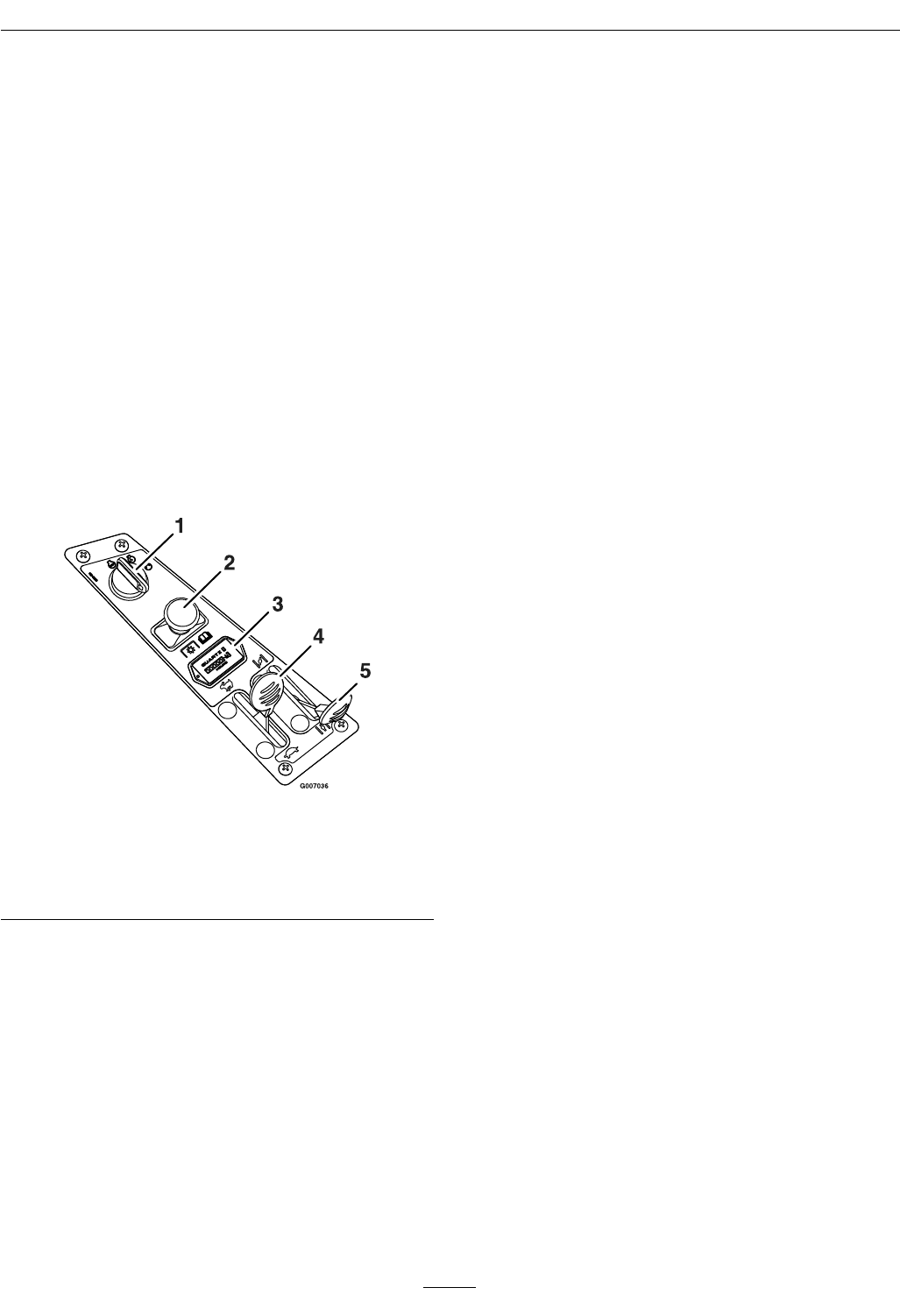
Figure4
1.Ignitionswitch4.Throttle
2.Bladecontrolswitch
(powertake-off)
5.Choke
3.Hourmeter
Note:Brakemustbeengaged,motioncontrollevers
out(neutrallockposition)andPTOswitch“OFF”to
startengine.(Itisnotnecessaryfortheoperatorto
beintheseattostarttheengine.)
TurningthekeytotheOffpositionwillstopthe
engine;however,alwaysremovethekeywhenleaving
themachinetopreventsomeonefromaccidentally
startingtheengine
BladeControlSwitch(Power
Take-Off)
Locatedonthecontrolpanel.
Thebladecontrolswitch,representedbyapower
take-off(PTO)symbol,engagesanddisengages
powertothemowerblades.
Pulloutonthebladecontrolswitchto“On”to
engagetheblades
Pushthebladecontrolswitchto“Off”todisengage
theblades
ChokeControl
Locatedoncontrolpanel.
Thechokeisusedtoaidinstartingacoldengine.Do
Notrunawarmenginewiththechokeinthe“ON”
position.Movingthechokeleverforwardwillputthe
chokeinthe“ON”positionandmovingthechoke
levertotherearwillputthechokeinthe“OFF”
position(Figure4).
ThrottleControl
Locatedoncontrolpanel.
Thethrottleisusedtocontrolenginespeed.Moving
throttleleverforwardwillincreaseenginespeedand
movingthrottlelevertotherearwilldecreaseengine
speed.Movingthethrottleforwardintothedetentis
fullthrottle(seeFigure4).
MotionControlLevers
Themotioncontrolleverslocatedoneachsideof
theseat(Figure3).
Themotioncontrolleversarespeedsensitivecontrols
ofindependentwheelmotors.Movingalever
forwardorbackwardturnsthewheelonthesameside
forwardorinreverse;wheelspeedisproportionalto
theamounttheleverismoved.Movingthecontrol
leversoutwardfromthecenterpositionlocksthem
intheneutralposition.Alwayspositionthemotion
controlleversintotheneutralpositionandengage
theparkbrakeleverwhenyoustopthemachineor
leaveitunattended.Theunitmustbetieddownand
brakeengagedwhentransporting.
16
Operation
ParkingBrakeLever
Locatedonleftsideoftheconsole(Figure3).
Thebrakeleverengagesaparkingbrakeonthedrive
wheels.
Pulltheleverupandrearwardtoengagethebrake.
Pushtheleverforwardanddowntodisengagethe
brake.
Height-of-CutFootLever
Theheightofcutleverallowstheoperatortolower
andraisethedeckfromtheseatedposition(Figure3).
Whentheleverismovedforward,awayfromthe
operatorthedeckisraisedfromthegroundand
whenmovedback,towardstheoperatoritislowered
towardtheground.Onlyadjusttheheightofcut
whilemachineisnotmoving.
HourMeter
Locatedonthecontrolpanel.
Thehourmeterisconnectedtoapressureswitch
installedintheengineblockanditrecordsthenumber
ofhoursthattheenginehasrun(Figure4).Ifthe
ignitionswitchisleftonwithoutenginerunning,
hourmeterwillnotrun.
Note:Thisswitchisnotalowoilsensorandwillnot
alerttheoperatoriftheengineoilislow .
OperatingInstructions
ThinkSafetyFirst
Note:Determinetheleftandrightsidesofthe
machinefromthenormaloperatingposition.
Pleasecarefullyreadallofthesafetyinstructions
anddecalsinthesafetysection.Knowingthis
informationcouldhelpyou,yourfamily,petsor
bystandersavoidinjury.
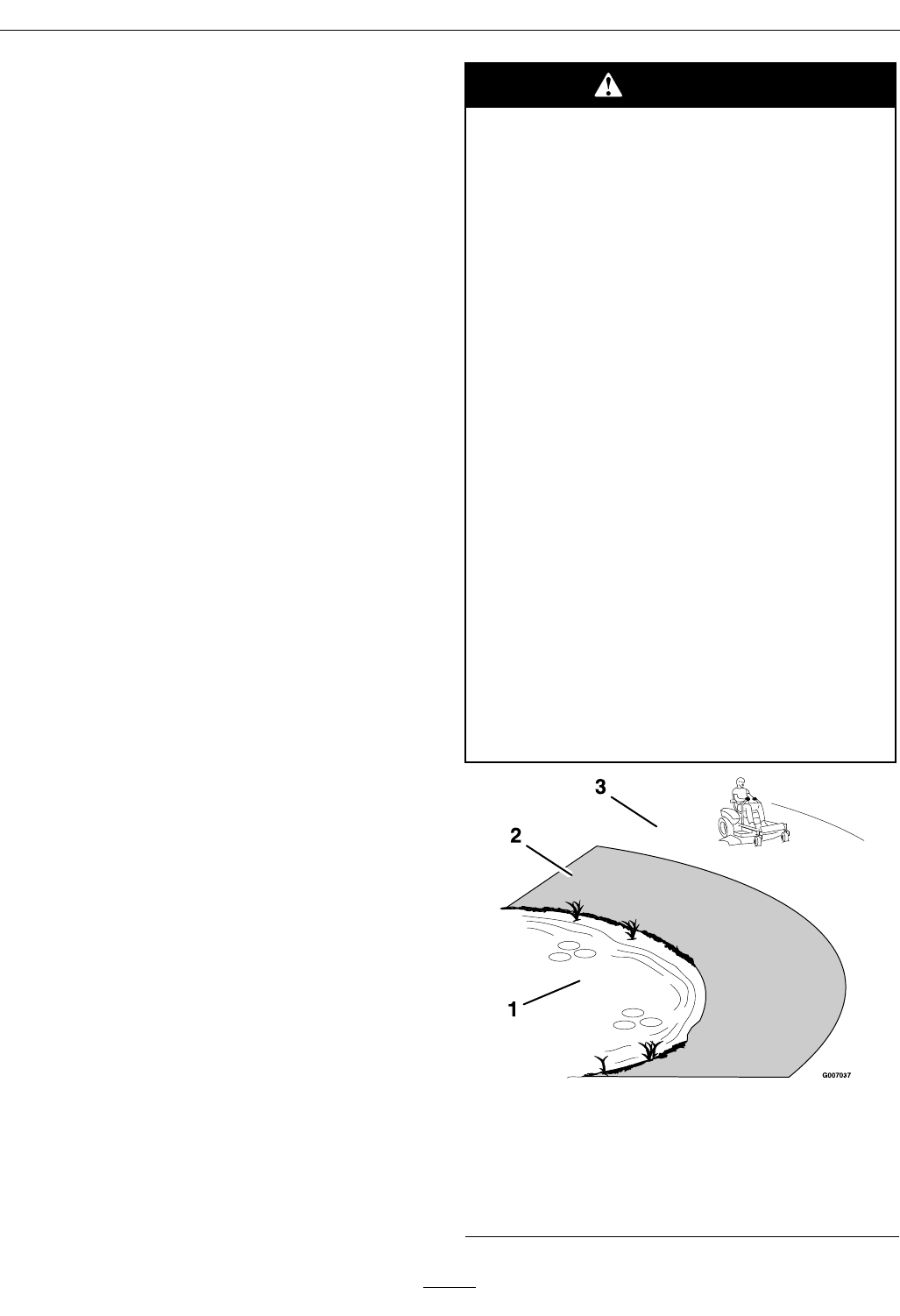
DANGER
Mowingonwetgrassorsteepslopescan
causeslidingandlossofcontrol.Wheels
droppingoveredgescancauserollovers,
whichmayresultinseriousinjury,death
ordrowning.Alossoftractionisalossof
steeringcontrol.
Toavoidlossofcontrolandpossibilityof
rollover:
•Donotmowneardrop-offsornearwater.
•Donotmowslopesgreaterthan15
degrees.
•Reducespeedanduseextremecaution
onslopes.
•Whenmowingslopes,graduallywork
fromlowertohigherareasontheincline.
•Avoidsuddenturnsorrapidspeed
changes.
•Turnup,intoaninclinewhenchanging
directionsonslopes.Turningdownthe
slopereducestraction.
•Attachmentschangethehandling
characteristicsofthemachine.Useextra
cautionwhenusingattachmentswiththe
machine.
Figure5
1.Water3.SafeZone-usetheQuest
here.
2.Usewalkbehindmower
and/orhandtrimmer
neardrop-offsand
water.
17

Operation
Seeinsidebackcovertodeterminetheapproximate
slopeangletobemowed.
RecommendedGasoline
UseUNLEADEDRegularGasolinesuitablefor
automotiveuse(87pumpoctaneminimum).
Important:Neverusemethanol,gasoline
containingmethanol,orgasoholcontaining
morethan10%ethanolbecausethefuelsystem
couldbedamaged.DoNotmixoilwithgasoline.
DANGER
Incertainconditionsgasolineisextremely
ammableandvaporsareexplosive.
Areorexplosionfromgasolinecanburn
you,others,andcausepropertydamage.
•Fillthefueltankoutdoorsinanopen
area,whentheengineiscold.Wipeup
anygasolinethatspills.
•Neverrellthefueltankordrainthe
machineindoorsorinsideanenclosed
trailer.
•DoNotllthefueltankcompletelyfull.
Addgasolinetothefueltankuntilthe
bodyofthetankisfullbutfueldoesnot
lltheneckofthetank.Thisemptyspace
inthetankallowsgasolinetoexpand.
•Neversmokewhenhandlinggasoline,
andstayawayfromanopenameor
wheregasolinefumesmaybeignitedby
spark.
•Storegasolineinanapprovedcontainer
andkeepitoutofthereachofchildren.
Neverbuymorethana30-daysupplyof
gasoline.
•DoNotoperatewithoutentireexhaust
systeminplaceandinproperworking
condition.
DANGER
Incertainconditionsduringfueling,static
electricitycanbereleasedcausingaspark
whichcanignitegasolinevapors.Areor
explosionfromgasolinecanburnyouand
othersandcausepropertydamage.
•Alwaysplacegasolinecontainersonthe
groundawayfromyourvehiclebefore
lling.
•DoNotllgasolinecontainersinsidea
vehicleoronatruckortrailerbedbecause
interiorcarpetsorplastictruckbedliners
mayinsulatethecontainerandslowthe
lossofanystaticcharge.
•Whenpractical,removegas-powered
equipmentfromthetruckortrailerand
refueltheequipmentwithitswheelson
theground.
•Ifthisisnotpossible,thenrefuelsuch
equipmentonatruckortrailerfroma
portablecontainer,ratherthanfroma
gasolinedispensernozzle.
•Ifagasolinedispensernozzlemustbe
used,keepthenozzleincontactwiththe
rimofthefueltankorcontaineropening
atalltimesuntilfuelingiscomplete.
WARNING
Gasolineisharmfulorfatalifswallowed.
Long-termexposuretovaporshascaused
cancerinlaboratoryanimals.Failuretouse
cautionmaycauseseriousinjuryorillness.
•Avoidprolongedbreathingofvapors.
•Keepfaceawayfromnozzleandgas
tank/containeropening.
•Keepawayfromeyesandskin.
•Neversiphonbymouth.
18

Operation
UsingStabilizer/Conditioner
Useafuelstabilizer/conditionerinthemachineto
providethefollowingbenets:
•Keepsgasolinefreshduringstorageof30daysor
less.Forlongerstorageitisrecommendedthat
thefueltankbedrained.
•Cleanstheenginewhileitruns.
•Eliminatesgum-likevarnishbuildupinthefuel
system,whichcauseshardstartingAddthe
correctamountofgasstabilizer/conditionerto
thegas.
Note:Afuelstabilizer/conditionerismosteffective
whenmixedwithfreshgasoline.Tominimizethe
chanceofvarnishdepositsinthefuelsystem,usefuel
stabilizeratalltimes.
Gasoline/Alcoholblends
Gasohol(upto10percentethylalcohol,90percent
unleadedgasolinebyvolume)isapprovedforfueluse
bytheenginemanufacturer.Othergasoline/alcohol
blendsarenotapproved.
FillingtheFuelTank
1.Shuttheengineoffandsetthemotioncontrols
totheneutralpositionandengageparkingbrake.
2.Cleanaroundthefueltankcapandremovethe
cap.
3.Addunleadedregulargasolineuntilthebodyof
thetankisfullbutfueldoesnotlltheneckof
thetank(Figure6).Thisspaceintheneckofthe
tankallowsgasolinetoexpand.Donotllthe
fueltankcompletelyfull.
Figure6
1.Gastankopening3.Gastankbody
2.Filltohere,
approximately
4.Installthefueltankcapsecurely.Wipeupany
gasolinethatmayhavespilled.
CheckingtheEngineOil
Level
Beforeyoustarttheengineandusethemachine,
checktheoillevelintheenginecrankcase;referto
CheckingtheOilLevelinEngineMaintenance.
StartingtheEngine
1.Sitdownontheseatandmovethemotion
controlsoutwardtotheneutralpositionand
engagetheparkingbrake.
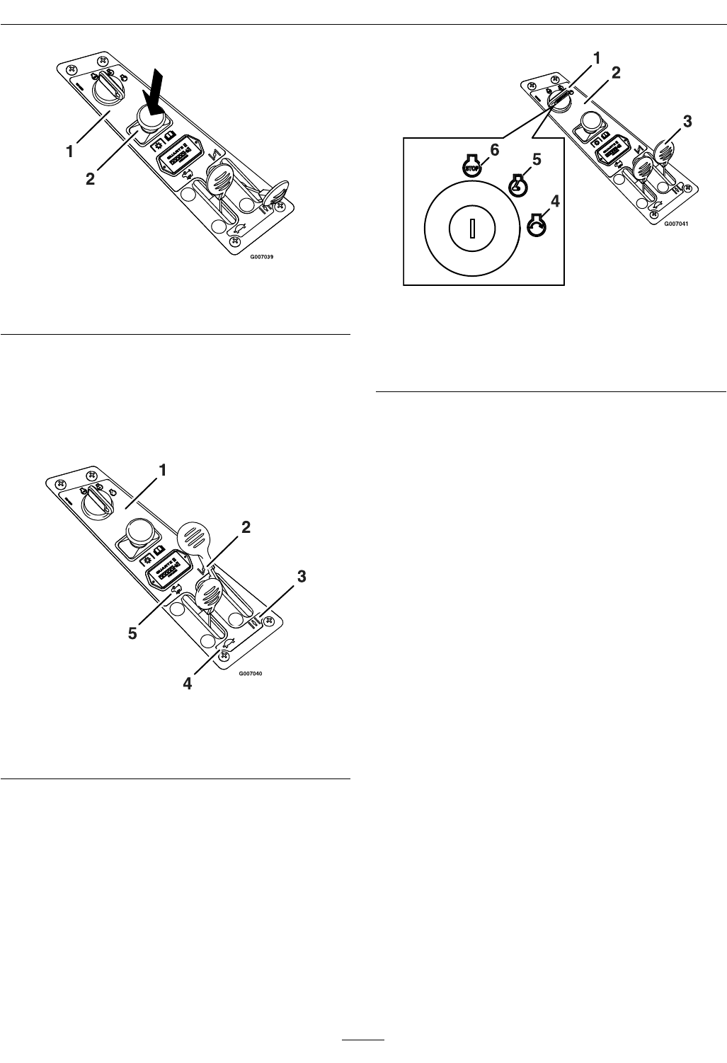
2.Disengagethebladesbymovingthebladecontrol
switchtoOff(Figure7).
19
Operation
Figure7
1.Controlpanel2.Bladecontrol
switch—Offposition
3.Movethethrottlelevertomidwayandthechoke
leverforwardbeforestartingacoldengine
(Figure8).
Note:Awarmorhotenginemaynotrequire
choking.
Figure8
1.Controlpanel4.Throttle—slow
2.Choke—on5.Throttle—fast
3.Choke–off
4.TurntheignitionkeytoStarttoenergizethe
starter.Whentheenginestarts,releasethekey
(Figure9).
Important:Donotengagethestarterfor
morethan5secondsatatime.Iftheengine
failstostart,allowa60secondcool-down
periodbetweenattempts.Failuretofollow
theseinstructionscanburnoutthestarter
motor.
Figure9
1.Ignitionkey—start
position
4.Start
2.Controlpanel5.Run
3.Choke6.Off
5.Iftheenginestallsorhesitates,movethe
chokeleverpartiallyforwardforafewseconds
(Figure9).
OperatingtheBlades
Thebladecontrolswitch,representedbyapower
take-off(PTO)symbol,engagesanddisengages
powertothemowerblades.Thisswitchcontrols
powertoanyattachmentsthatdrawpowerfromthe
engine,includingthemowerdeckandcuttingblades.
EngagingtheBlades
1.Releasepressureonthemotioncontrolleversand
placethemachineinneutral.
2.MovethethrottlemidwaytotheFastposition.
Note:Alwaysengagethebladeswiththethrottle
inthemidwayposition.
3.PulloutonthebladecontrolswitchtoOnto
engagetheblades(Figure10).
20
Operation
Figure10
1.Controlpanel2.Bladecontrol
switch—Onposition
4.Movethrottletofullforwardpositionbefore
mowing.
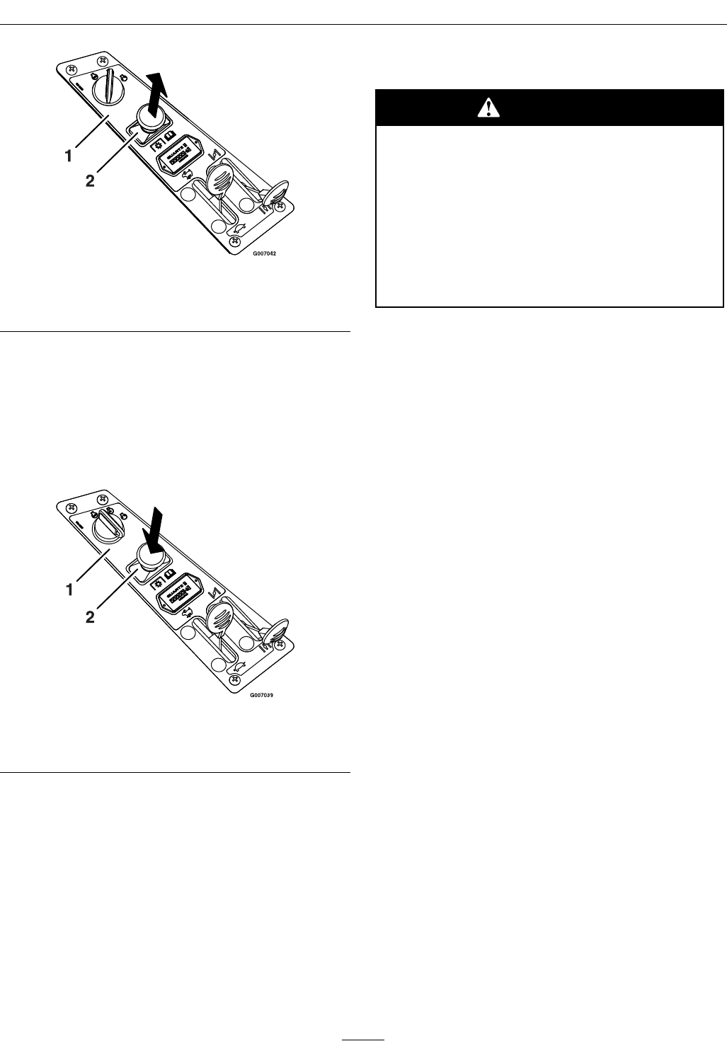
DisengagingtheBlades
Setthrottletomidwayposition.Pushtheblade
controlswitchtoOfftodisengagetheblades
(Figure11).
Figure11
1.Controlpanel2.Bladecontrol
switch—Offposition
StoppingtheEngine
1.MovethethrottlelevertobetweenFastandhalf
throttle(Figure9).
2.Disengagethebladesbymovingthebladecontrol
switchtoOff(Figure11).
3.TurntheignitionkeytoOff(Figure9).
4.Pullthewireoffofthesparkplug(s)toprevent
thepossibilityofsomeoneaccidentallystarting
themachinebeforetransportingorstoringthe
machine.
TheSafetyInterlockSystem
CAUTION
Ifsafetyinterlockswitchesaredisconnected
ordamagedthemachinecouldoperate
unexpectedlycausingpersonalinjury.
•DoNottamperwiththeinterlock
switches.
•Checktheoperationoftheinterlock
switchesdailyandreplaceanydamaged
switchesbeforeoperatingthemachine.
UnderstandingtheSafetyInterlock
System
Thesafetyinterlocksystemisdesignedtopreventthe
enginefromstartingunless:
•Thebladesaredisengaged.
•Themotioncontrolleversareintheneutral
position.
•Theparkingbrakeisengaged.
Thesafetyinterlocksystemisdesignedtoinitiate
engineshutdownwhen:
•Theparkingbrakeisdisengagedandtheoperator
getsoffmachine.
•ThePTOisengagedandtheoperatorgetsoff
machine.
•Theparkingbrakeisdisengagedandleversarein
andtheoperatorgetsoffmachine.
•Theparkingbrakeisengagedandmotioncontrol
leversarein.
TestingtheSafetyInterlockSystem
Testthesafetyinterlocksystembeforeyouusethe
machineeachtime
1.Checkstartingcircuit.Startershouldcrankwith
parkingbrakeengaged,PTOdisengagedand
motioncontrolleversmovedoutintheneutral
lockposition.Theoperatordoesnotneedtobe
intheseattostarttheengine.
Trytostartwithoperatorinseat,parkingbrake
disengaged,PTOdisengagedandmotioncontrol
leversintheneutrallockposition-startermust
notcrank.
21
Operation
Trytostartwithoperatorinseat,parkingbrake
engaged,PTOengagedandmotioncontrol
leversintheneutrallockposition-startermust
notcrank.
Trytostartwithoperatorinseat,parkingbrake
engaged,PTOdisengaged,andtheleftmotion
controlleverin,startermustnotcrank,repeat
againwiththerightleverin,thenwithboth
leversin-startermustnotcrank.
2.Checkkillcircuits.Runengineatone-third
throttle,disengageparkingbrakeandraiseoff
ofseat(butdonotgetoffofmachine)engine
mustinitiateshutdown.
Runengineatone-thirdthrottle,engagePTO
andraiseoffofseat(butdonotgetoffof
machine)enginemustinitiateshutdown.
Runengineatone-thirdthrottle,withbrake
disengaged,moveleversinandraiseoffseat(but
donotgetoffofmachine)enginemustinitiate
shutdown.
Again,runengineatone-thirdthrottle,brake
engaged,andmoveleftmotioncontrolleverin
-enginemustinitiateshutdown.
Repeatagainmovingtherightleverin,then
movingbothleversin-enginemustinitiate
shutdownwhetheroperatorisonseatornot.
Note:Ifmachinedoesnotpassanyofthesetests,
donotoperate.ContactyourauthorizedEXMARK
SERVICEDEALER.
Important:Itisessentialthatoperatorsafety
mechanismsbeconnectedandinproper
operatingconditionpriortouseformowing.
DrivingForwardorBackward
Thethrottlecontrolregulatestheenginespeedas
measuredinrpm(revolutionsperminute).Place
thethrottlecontrolintheFastpositionforbest
performance.AlwaysoperateintheFast(fullthrottle)
position.
CAUTION
Machinecanspinveryrapidlybypositioning
onelevertoomuchaheadoftheother.
Operatormaylosecontrolofthemachine,
whichmaycausedamagetothemachine
orinjury.
•Usecautionwhenmakingturns.
•Slowthemachinedownbeforemaking
sharpturns.
Forward
1.Movetheleverstothecenter,unlockedposition.
2.Togoforward,slowlypushthemotioncontrol
leversforward(Figure12).
Figure12
1.Neutralposition3.Backward
2.Centerunlockposition4.Forward
Togostraight,applyequalpressuretoboth
motioncontrollevers(Figure12).
Toturn,pullbackonthemotioncontrollever
towardthedirectionyouwanttoturn(Figure12).
Thefartheryoumovethemotioncontrollevers
ineitherdirection,thefasterthemachinewill
moveinthatdirection.
Tostop,pullthemotioncontrolleverstoneutral.
22
Operation
Backward
1.Movetheleverstothecenter,unlockedposition.
2.Togobackward,slowlypullthemotioncontrol
leversrearward(Figure12).
Togostraight,applyequalpressuretoboth
motioncontrollevers(Figure12).
Toturn,releasethepressureonthemotion
controllevertowardthedirectionyouwantto
turn(Figure12).
Tostop,pushthemotioncontrolleverstoneutral.
StoppingtheMachine
Tostopthemachine,movethemotioncontrol
leverstoneutralandoutwardtotheneutralposition,
disengagethebladecontrolswitch,movethethrottle
levertobetweenFastandhalfthrottle,andturnthe
ignitionkeytooff.Remembertoremovethekey
fromtheignitionswitch.
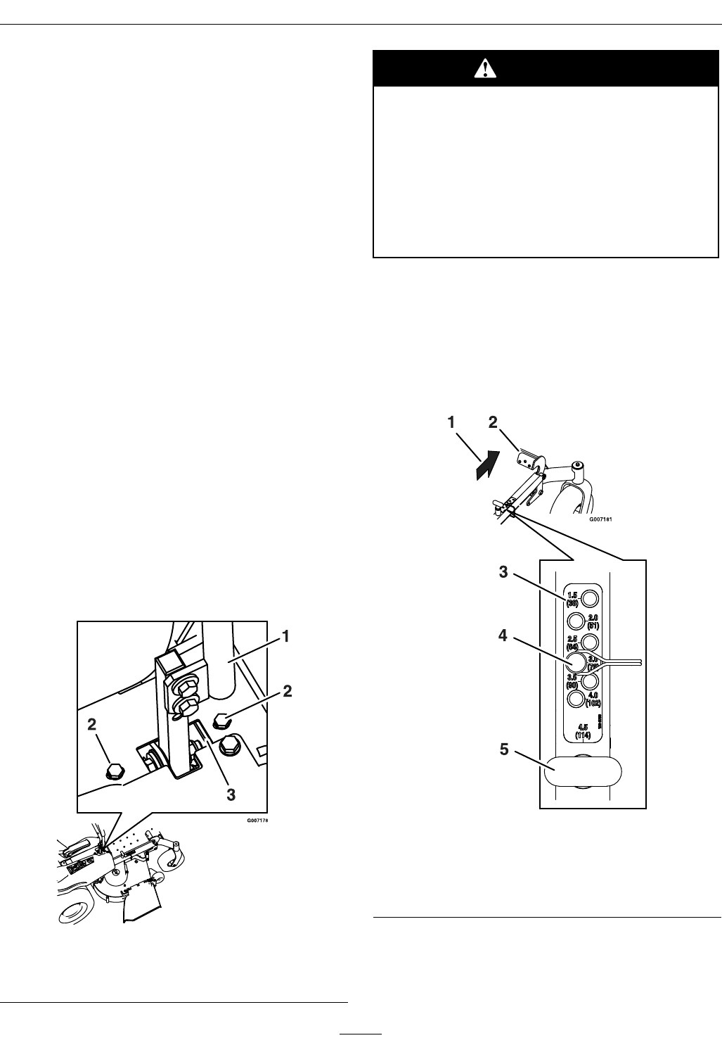
TrackingAdjustment
Ifthemachineturnsrightorleftwhenhandlesare
pushedforwardtogether,adjustthestopontheside
oppositethedirectionofturn(seeFigure13).Loosen
thescrewsthatholdthemotioncontrollimiterstop.
Movethestopbackuntiltheunitdrivesstraight.
Tightenthescrewstolockthestopinplace.Readjust
handlesifnecessary.
Figure13
1.Controlarmshaft3.Adjuststop
2.Limiterstopscrews
CAUTION
Childrenorbystandersmaybeinjuredifthey
moveorattempttooperatethemowerwhile
itisunattended.
Alwaysremovetheignitionkeyandmovethe
motioncontrolleversoutwardtotheneutral
positionandapplytheparkingbrakewhen
leavingthemachineunattended,evenifjust
forafewminutes.
AdjustingtheHeightofCut
1.Raisethedecktothetransportposition(4.5inch
(114mm)cutheight)bypushingthefootactuated
leverforward(Figure14).Thespringloaded
transportpinwillautomaticallyengageandwill
clickintoplace.
Figure14
1.Pushforward4.Heightadjusterpin
2.Footactuated
height-of-cutlever
5.Transportreleasehandle
3.Height-of-cutpositions
2.Movethedeckheightadjusterpintothedesired
cutheight.
3.Pushthefootleverforward,pullthetransport
releasehandleupandletthedecklowerdownto
23
Operation
thepredeterminedcutheightbyslowlydecreasing
footpressureallowingthefootlevertotravel
rearward.
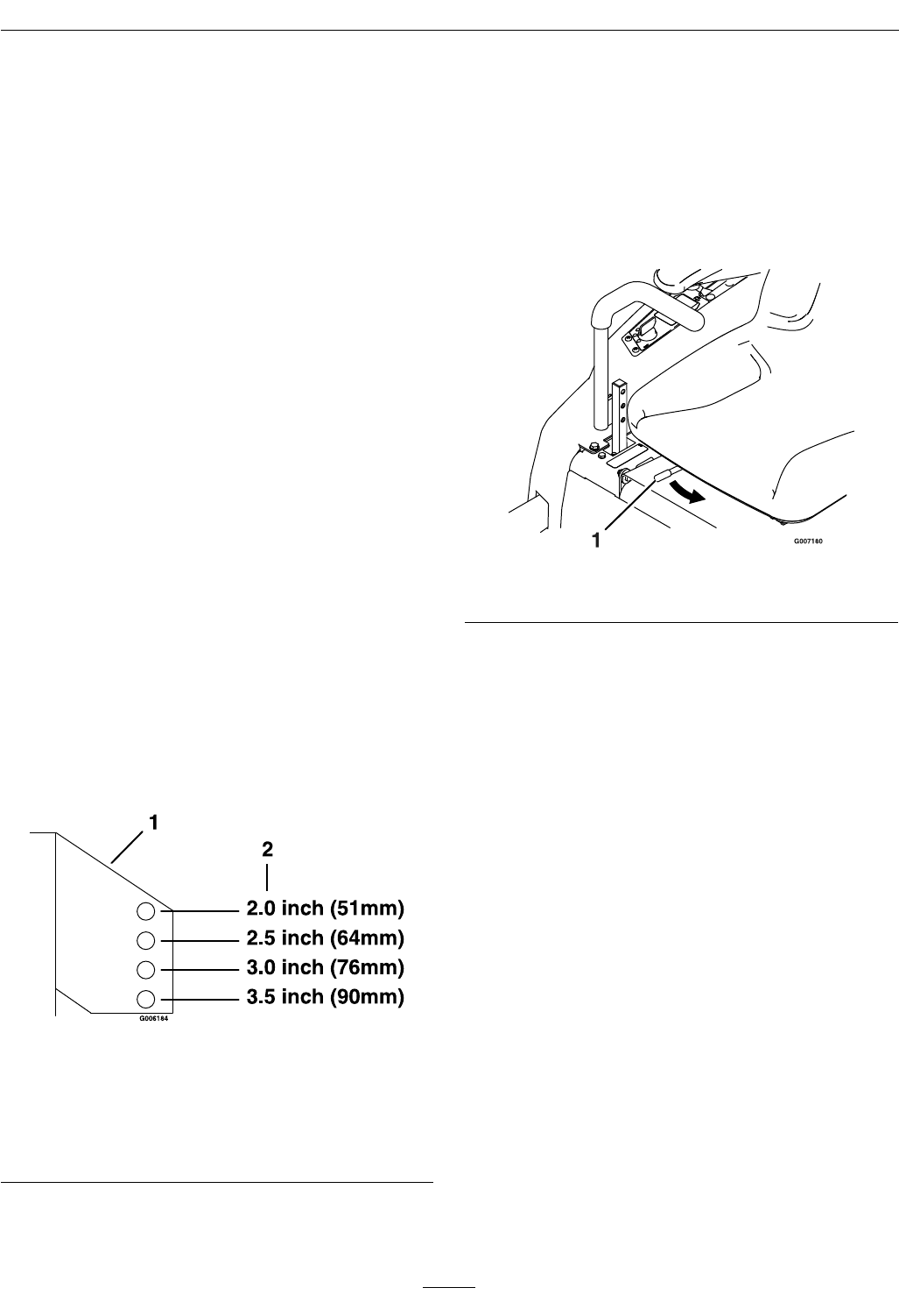
AdjustingtheAnti-Scalp
Rollers
Itisrecommendedtochangetheanti-scalproller
positionwhentheheightofcuthaschanged.
1.Stopthemachineandmovethedriveleversto
theneutrallockposition.
2.DisengagethePTO.
3.Engagetheparkbrake.
4.Stoptheengine,removethekeyandwaitforall
movingpartstostop.
5.Afteradjustingtheheightofcut,adjustthe
anti-scalprollersbyremovingthenylocnut.
6.Adjusttheanti-scalprollersforthenormal
operatingconditions.Placerollersinoneof
thepositionsshowninFigure15.Rollerswill
maintain3/4inches(19mm)clearancetothe
groundtominimizegougingandrollerwearor
damage.
Note:ForMaximumDeckFlotation,place
therollersoneholepositionlower.Rollersshould
maintain1/4inch(6.35mm)clearancetothe
ground.DoNotadjustrollerstosupportthe
deck.
Figure15
Forcuttingheightsabove31/2inches(38mm)usethe
bottomhole.Therollerswillstillbeeffectiveagainst
scalping.
1.Anti-scalproller
mountingbracket
2.Cuttingheight
7.Torquehardwareto27-33ft-lb(37-45N-m)or
lossofrollermayresult.
PositioningtheSeat
Theseatcanmoveforwardandbackward.Position
theseatwhereyouhavethebestcontrolofthe
machineandaremostcomfortable.
1.Pushtheadjustmentlevertowardsthecenterof
themachinetoreleasetheseatadjustertrack
(Figure16).
Figure16
1.Adjustmentlever
2.Movetheseattothedesiredpositionandrelease
thelevertolockinthatposition.
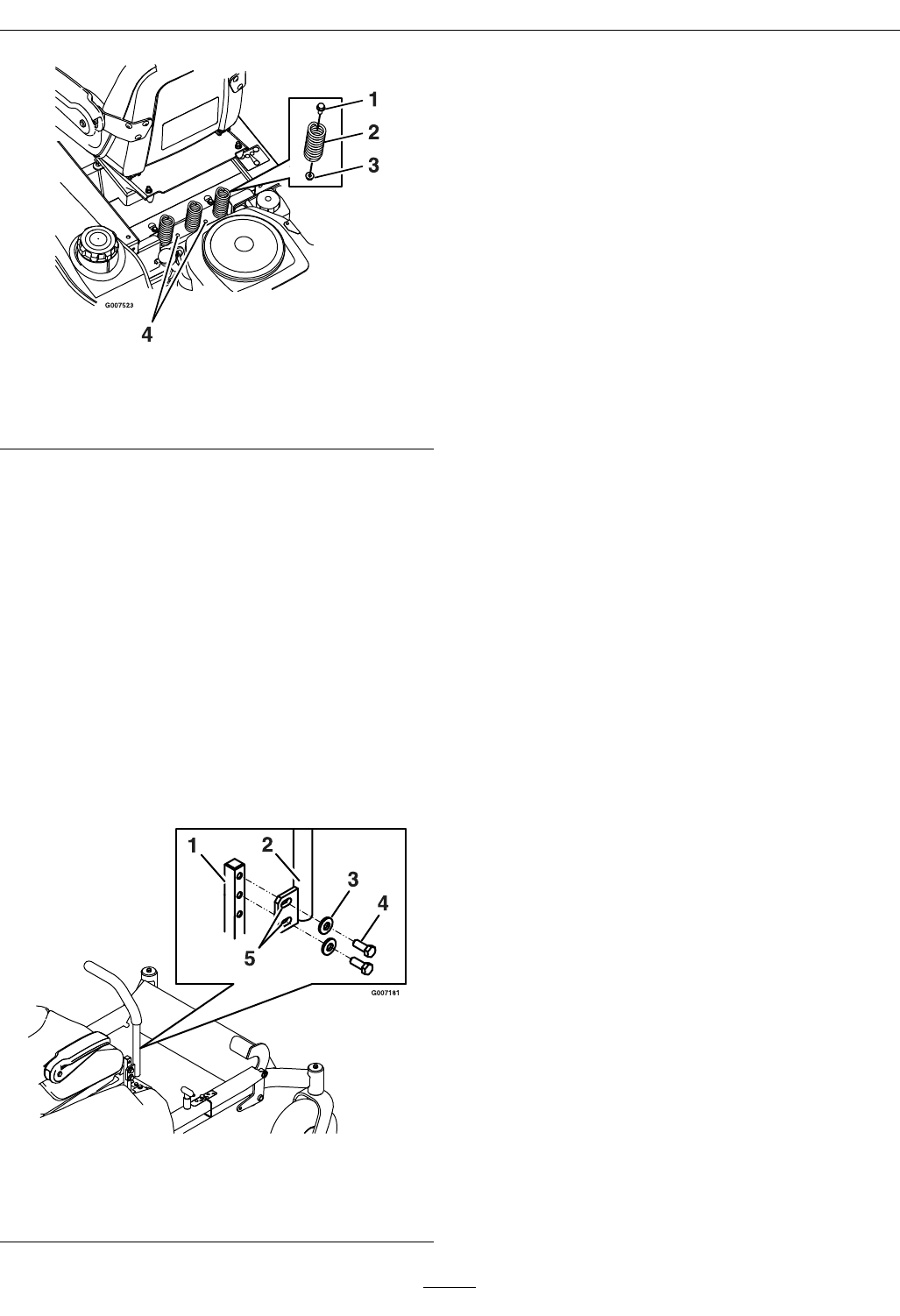
ChangingtheSeatRide
Suspension
Thenumberofseatspringscanbechangedto
maximizeridercomfort.Morespringsshouldbeused
withheavieroperatorsandonroughterrain.Fewer
springsshouldbeusedwithlighteroperatorsand
whenmowingsmooth,wellestablishedlawns.Always
keepthenumberofspringsontheleftandrightside
thesamewhenaddingandremovingsprings.
24
Operation
Figure17
1.Bolt3.Nut
2.Spring4.Additionalmounting
holes
Uptovespringscanbesecuredtotheseatboxwith
anutandbolt,seeFigure17.
RefertoyourPartsManualforspringandhardware
partnumbers.
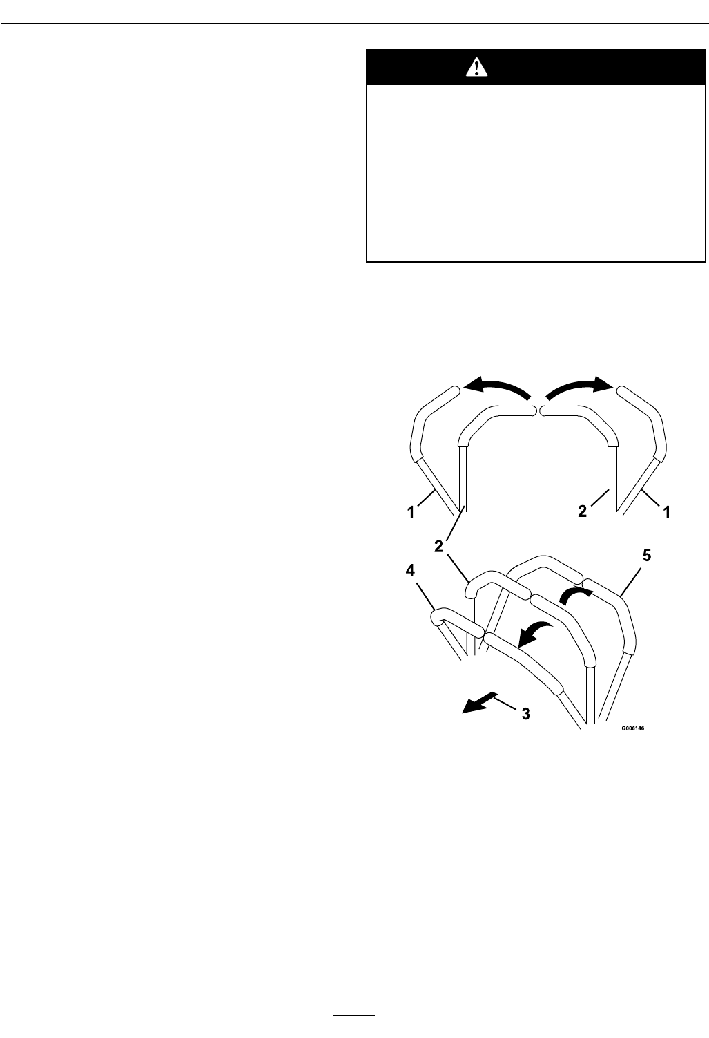
AdjustingtheMotionControl
Levers
AdjustingtheHeight
Themotioncontrolleverscanbeadjustedhigheror
lowerformaximumoperatorcomfort.
1.Removethetwoboltsholdingthecontrolleverto
thecontrolarmshaft(Figure18).
Figure18
1.Controlarmshaft4.Bolt
2.Controllever5.Slottedholes
3.Washer
2.Movethecontrollevertothenextsetofholes.
Securetheleverwiththetwobolts.
3.Repeattheadjustmentfortheoppositecontrol
lever.
AdjustingtheTilt
Themotioncontrolleverscanbetiltedforeoraftfor
maximumoperatorcomfort.
1.Loosentheupperboltholdingthecontrollever
tothecontrolarmshaft.
2.Loosenthelowerboltjustenoughtopivotthe
controlleverforeoraft(Figure18).Tightenboth
boltstosecurethecontrolinthenewposition.
3.Repeattheadjustmentfortheoppositecontrol
lever.
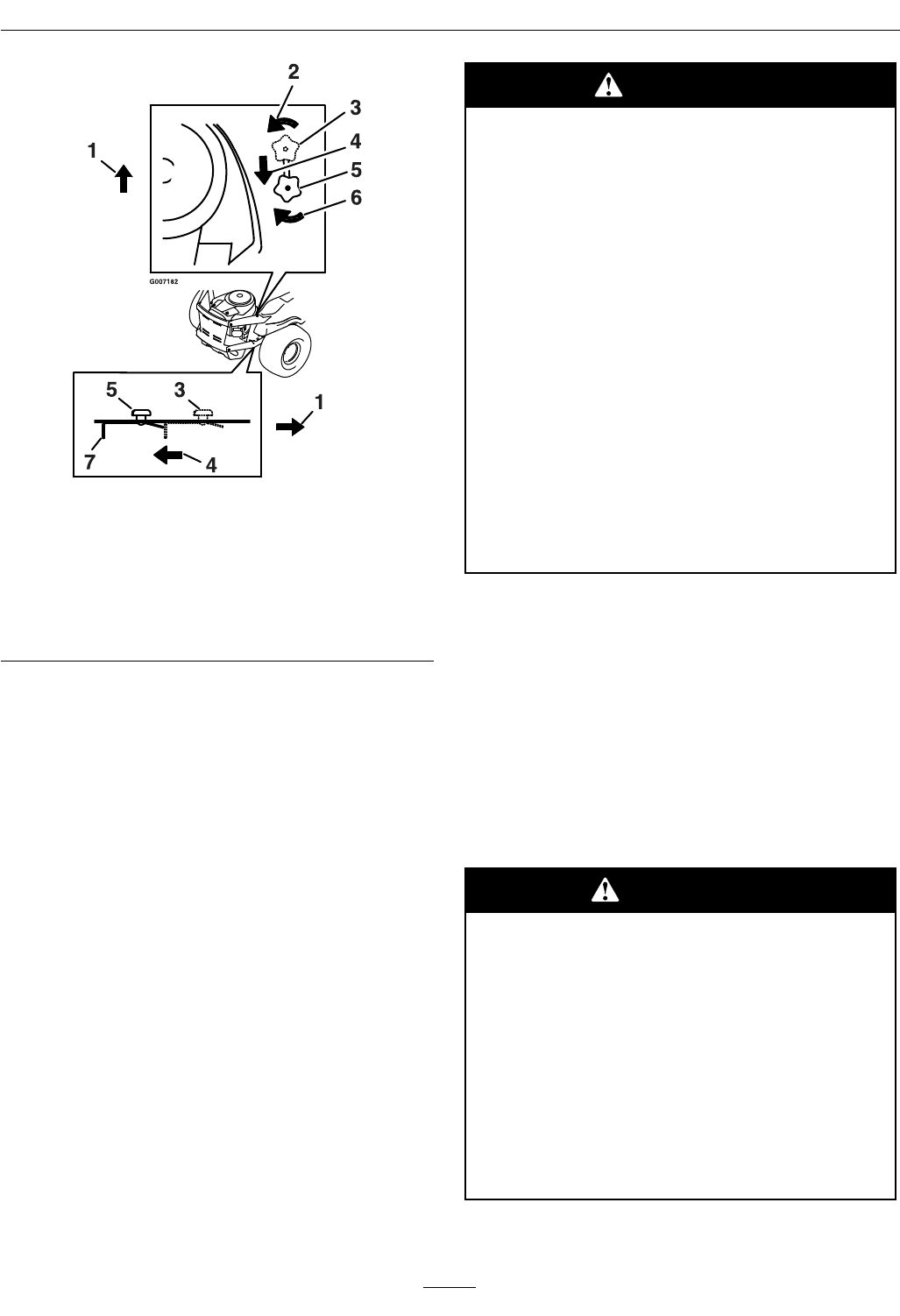
PushingtheMachineby
Hand
Important:Alwayspushthemachinebyhand.
Nevertowthemachinebecausedamagemay
occur.
ToPushtheMachine
1.Parkthemachineonalevelsurfaceanddisengage
thebladecontrolswitch.
2.Movethemotioncontrolleversoutwardto
neutralposition,engageparkingbrake,stopthe
engine,removethekey,andwaitforallmoving
partstostopbeforeleavingtheoperatingposition.
3.Locatethebypassreleaseknobsoneithersideof
theenginedeck(Figure19).
25
Operation
Figure19
1.Frontofthemachine.5.Leverpositionfor
pushingthemachine
2.Rotatebypassrelease
knobcounterclockwise
6.Rotatebypassrelease
knobclockwise
3.Leverpositionfor
operatingthemachine.
7.Releaselever
4.Pullleverinthisdirection
4.Loosentheknobbyturningcounterclockwise.
Thenpullthereleaseleverontheundersideof
machine(Figure19)towardsthebackofthe
machineandretightentheknobtoholdthe
releaseleverbackinthereleasedstate.Repeatthis
oneachsideofthemachine.
5.Releasetheparkingbrake.Themachineisnow
abletobepushedbyhand.
ToOperatetheMachine
Loosenthebypassknob,pushthereleaselevers
forward,andretightentheknobtoengagethedrive
system(Figure19).
SideDischarge
Themowerhasahingeddischargedeectorthat
dispersesclippingstothesideanddowntowardthe
turf.
DANGER
Withoutthedischargedeector,mulchkit,
orentiregrasscollectionsystemmountedin
place,youandothersareexposedtoblade
contactandthrowndebris.Contactwith
rotatingmowerblade(s)andthrowndebris
willcauseinjuryordeath.
•Neverremovethedischargedeector
fromthemowerbecausethedischarge
deectorroutesmaterialdowntoward
theturf.Ifthedischargedeectorisever
damaged,replaceitimmediately.
•Neverputyourhandsorfeetunderthe
mower.
•Nevertrytocleardischargeareaor
mowerbladesunlessyoumovethemove
thebladecontrolswitchtoOffandrotate
theignitionkeytoOff.Alsoremovethe
keyandpullthewireoffthesparkplug(s).
Transporting
TransportingaUnit
Useaheavy-dutytrailerortrucktotransportthe
machine.Lockbrakeandblockwheels.Securely
fastenthemachinetothetrailerortruckwithstraps,
chains,cable,orropes.Besurethatthetrailerortruck
hasallnecessarylightingandmarkingasrequiredby
law .Secureatrailerwithasafetychain.
CAUTION
Thisunitdoesnothaveproperturn
signals,lights,reectivemarkings,ora
slowmovingvehicleemblem.Drivingona
streetorroadwaywithoutsuchequipment
isdangerousandcanleadtoaccidents
causingpersonalinjury.Drivingonastreet
orroadwaywithoutsuchequipmentmayalso
beaviolationofStatelawsandtheoperator
maybesubjecttotrafcticketsand/ornes.
DoNotdriveaunitonapublicstreetor
roadway.
26

Operation
WARNING
Loadingaunitonatrailerortruckincreases
thepossibilityofbackwardtip-over.
Backwardtip-overcouldcauseseriousinjury
ordeath.
•Useextremecautionwhenoperatinga
unitonaramp.
•Useonlyasingle,fullwidthramp;Do
Notuseindividualrampsforeachside
oftheunit.
•Ifindividualrampsmustbeused,use
enoughrampstocreateanunbroken
rampsurfacewiderthantheunit.
•DoNotexceeda15°anglebetweenramp
andgroundorbetweenrampandtrailer
ortruck.
•Avoidsuddenaccelerationwhiledriving
unituparamptoavoidtippingbackward.
•Avoidsuddendecelerationwhilebacking
unitdownaramptoavoidtipping
backward.
LoadingaUnit
Useextremecautionwhenloadingunitsontrailersor
trucks.Onefullwidthrampthatiswideenoughto
extendbeyondthereartiresisrecommendedinstead
ofindividualrampsforeachsideoftheunit.The
lowerrearsectionofthetractorframeextendsback
betweentherearwheelsandservesasastopfor
tippingbackward.Havingafullwidthrampprovides
asurfacefortheframememberstocontactifthe
unitstartstotipbackward.Ifitisnotpossibletouse
onefullwidthramp,useenoughindividualrampsto
simulateafullwidthcontinuousramp.
Rampshouldbelongenoughsothattheangles
betweentherampandthegroundandtherampand
thetrailerortruckdonotexceed15°.Asteeperangle
maycausemowerdeckcomponentstogetcaughtas
theunitmovesfromramptotrailerortruck.Steeper
anglesmayalsocausetheunittotipbackward.If
loadingonornearaslope,positionthetraileror
trucksoitisonthedownsideoftheslopeandthe
rampextendsuptheslope.Thiswillminimizethe
rampangle.Thetrailerortruckshouldbeaslevel
aspossible.
Important:DoNotattempttoturntheunit
whileontheramp,youmaylosecontroland
driveofftheside.
Avoidsuddenaccelerationwhendrivinguparamp
andsuddendecelerationwhenbackingdownaramp.
Bothmaneuverscancausetheunittotipbackward.
OperatingTips
FastThrottleSetting
Forbestmowingandmaximumaircirculation,
operatetheengineattheFastposition.Airisrequired
tothoroughlycutgrassclippings,sodonotsetthe
height-of-cutsolowastototallysurroundthemower
byuncutgrass.Alwaystrytohaveonesideofthe
mowerfreefromuncutgrass,whichallowsairtobe
drawnintothemower.
CuttingaLawnfortheFirstTime
Cutgrassslightlylongerthannormaltoensurethat
thecuttingheightofthemowerdoesnotscalpany
unevenground.However,thecuttingheightusedin
thepastisgenerallythebestonetouse.Whencutting
grasslongerthansixinchestall,youmaywanttocut
thelawntwicetoensureanacceptablequalityofcut.
Cut1/3oftheGrassBlade
Itisbesttocutonlyabout1/3ofthegrassblade.
Cuttingmorethanthatisnotrecommendedunless
grassissparse,oritislatefallwhengrassgrowsmore
slowly.
MowingDirection
Alternatemowingdirectiontokeepthegrassstanding
straight.Thisalsohelpsdisperseclippingswhich
enhancesdecompositionandfertilization.
MowatCorrectIntervals
Normally,moweveryfourdays.Butremember,
grassgrowsatdifferentratesatdifferenttimes.Soto
maintainthesamecuttingheight,whichisagood
practice,mowmoreofteninearlyspring.Asthe
grassgrowthrateslowsinmidsummer,mowless
frequently.Ifyoucannotmowforanextended
period,rstmowatahighcuttingheight;thenmow
againtwodayslateratalowerheightsetting.
27

Operation
CuttingSpeed
Toimprovecutquality,useaslowergroundspeed.
AvoidCuttingTooLow
Ifthecuttingwidthofthemoweriswiderthanthe
moweryoupreviouslyused,raisethecuttingheight
toensurethatuneventurfisnotcuttooshort.
LongGrass
Ifthegrassiseverallowedtogrowslightlylonger
thannormal,orifitcontainsahighdegreeof
moisture,raisethecuttingheighthigherthanusual
andcutthegrassatthissetting.Thencutthegrass
againusingthelower,normalsetting.
WhenStopping
Ifthemachine’sforwardmotionmustbestopped
whilemowing,aclumpofgrassclippingsmaydrop
ontoyourlawn.Toavoidthis,moveontoapreviously
cutareawiththebladesengaged.
KeeptheUndersideoftheMower
Clean
Cleanclippingsanddirtfromtheundersideofthe
moweraftereachuse.Ifgrassanddirtbuildupinside
themower,cuttingqualitywilleventuallybecome
unsatisfactory.
BladeMaintenance
Maintainasharpbladethroughoutthecuttingseason
becauseasharpbladecutscleanlywithouttearingor
shreddingthegrassblades.Tearingandshredding
turnsgrassbrownattheedges,whichslowsgrowth
andincreasesthechanceofdisease.Checkthe
cutterbladesdailyforsharpness,andforanywearor
damage.Filedownanynicksandsharpentheblades
asnecessary.Ifabladeisdamagedorworn,replace
itimmediatelywithagenuineExmarkreplacement
blade.OnlyExmarkbladesaretobeusedwiththis
unit.Nootherbladesareapproved.
28

Maintenance
Maintenance
Note:Determinetheleftandrightsidesofthemachinefromthenormaloperatingposition.
WARNING
Whilemaintenanceoradjustmentsarebeingmade,someonecouldstarttheengine.Accidental
startingoftheenginecouldseriouslyinjureyouorotherbystanders.
Removethekeyfromtheignitionswitch,engageparkingbrake,andpullthewire(s)offthespark
plug(s)beforeyoudoanymaintenance.Alsopushthewire(s)asidesoitdoesnotaccidentally
contactthesparkplug(s).
WARNING
Theenginecanbecomeveryhot.Touchingahotenginecancausesevereburns.
Allowtheenginetocoolcompletelybeforeserviceormakingrepairsaroundtheenginearea.
RecommendedMaintenanceSchedule(s)
MaintenanceService
IntervalMaintenanceProcedure
Aftertherst5hours•Changetheengineoil.
Aftertherst200hours•Changethehydraulicsystemlter.
Beforeeachuseordaily
•Checkthesafetyinterlocksystem.
•Checktheaircleanerfordirty,loose,ordamage.
•Checktheairintakeandcoolingareas,cleanasnecessary.
•Checktheoillevelbeforestartingorafterevery8hours.
•Checkthehydraulicoillevelintheexpansiontank.
•Checkthemowerblades.
•Cleanthemowerhousing.
Every25hours
•Greasealllubricationpoints.
•Servicetheaircleaner.(Mayneedmoreoftenunderextremelydustyordirtyconditions.)
•Checkthetirepressure.
•Checkthebelts.
Every100hours
•Replacethepaperelement.(Moreoftenunderextremelydusty,dirtyconditions.)
•Replacetheaircleanerelement.
•Changetheengineoilandlter.
•Cleantheblowerhousing.Moreoftenunderdirtyconditions.
•Replacethefuellter.
Every200hours•Servicethesparkplug.
Every500hours•Replacethesparkplug.
Beforestorage
•Chargethebatteryanddisconnectthebatterycables.
•Performallmaintenanceproceduresbeforestorage.
•Paintanychippedsurfaces.
Monthly•Checkthebatterycharge.
29
Maintenance
Important:RefertoyourEngineOperator’sManualforadditionalmaintenanceprocedures.
Premaintenance
Procedures
RaisingtheSeat
Makesurethemotioncontrolleversarelockedin
theneutralposition.Lifttheseatforwarduntilthe
lanyardistight.Thefollowingcomponentscanbe
accessedbyraisingtheseat:
•Auxiliary12VPlug(12Vaccessoryupto15amp)
•Fuses
•Batterycables
AccessingtheBattery
Thebatteryislocatedundertheseat.Toaccess,raise
theseat(Figure20).
Figure20
1.Auxiliary12VPlug3.Seat
2.Battery
PeriodicMaintenance
Lubrication
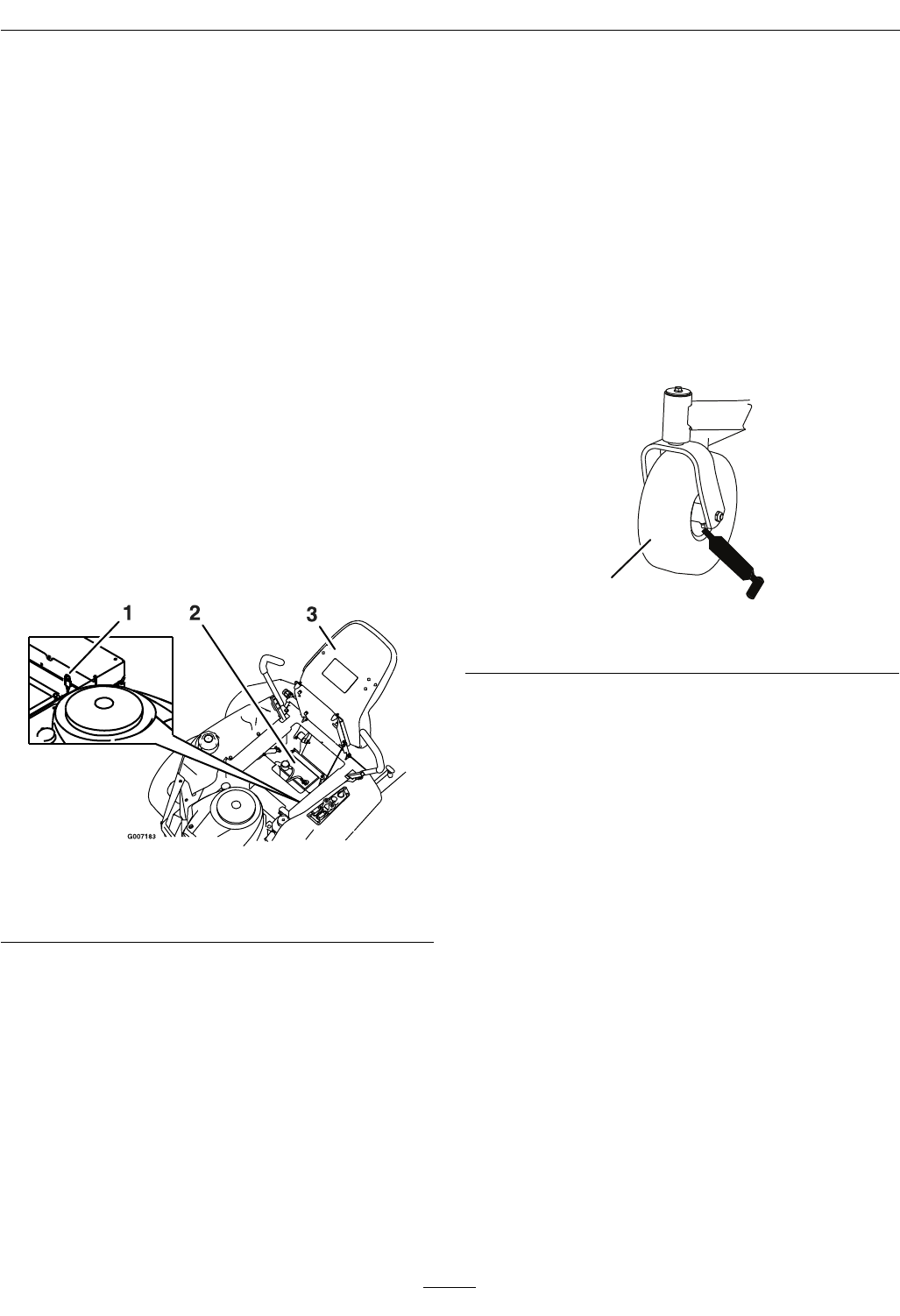
GreasingtheBearings
GreaseType:NGLIgrade#2multi-purposegun
grease.
Greasethefrontcasterpivotsandwheels(Figure21).
1
G007184
Figure21
1.Frontcastertire
1.Parkthemachineonalevelsurfaceanddisengage
thebladecontrolswitch.
2.Movethemotioncontrolleversoutwardtothe
neutralposition,engageparkingbrake,stopthe
engine,removethekey,andwaitforallmoving
partstostopbeforeleavingtheoperatingposition.
3.Cleanthegreasettings(Figure21andFigure22)
witharag.Makesuretoscrapeanypaintoffof
thefrontofthetting(s).
30
Maintenance
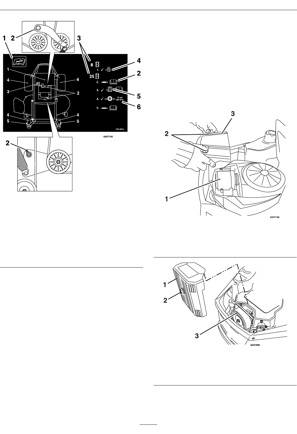
Figure22
Locatedonthebackoftheseat.
1.Readtheinstructions
beforeservicingor
performingmaintenance
4.Checkoillevel.
2.Greaseidlerpivots.5.Checkhydraulicoillevel
andrefertoOperator’s
manualforfurther
instructions.
3.Timeinterval.6.Checktirepressure.
4.Connectagreaseguntoeachtting(Figure21
andFigure22).Pumpgreaseintothettingsuntil
greasebeginstooozeoutofthebearings.
5.Wipeupanyexcessgrease.
EngineMaintenance
ServicingtheAirCleaner
ServiceInterval:Beforeeachuseordaily
Every100hours—Replace
thepaperelement.(More
oftenunderextremely
dusty,dirtyconditions.)
Thisengineisequippedwithareplaceable,high
densitypaperaircleanerelement.Checktheair
cleanerdailyorbeforestartingtheengine.Checkfor
abuildupofdirtanddebrisaroundtheaircleaner
system.Keepthisareaclean.Alsocheckforlooseor
damagedcomponents.Replaceallbentordamaged
aircleanercomponents.
Note:Operatingtheenginewithlooseordamaged
aircleanercomponentscouldallowunlteredairinto
theenginecausingprematurewearandfailure.
Note:Servicetheaircleanermoreoftenunder
extremelydusty,dirtyconditions.
Figure23
Briggs&Strattonengine
1.Aircleaner3.Aircleanercover
2.Knobs
Figure24
KohlerCommandengine
1.Aircleanercover3.Aircleaner
2.Knob
31

Maintenance
ServicingPaperElement
ServiceInterval:Every25hours(May
needmoreoftenunder
extremelydustyordirty
conditions.)
Every100hours/Yearly
(whichevercomes
rst)—Replacetheair
cleanerelement.
1.Removetheaircleanercover(Figure23).
2.Removetheaircleanerelementwiththeintegral
rubberseal.
3.Gentlytapthepleatedsideofthepaperelement
todislodgedirt.DoNotwashthepaperelement
orusepressurizedair,asthiswilldamagethe
element.Replaceadirty,bent,ordamaged
element.Handlenewelementscarefully;DoNot
useiftherubbersealorfoamsleeveisdamaged.
4.Cleanallaircleanercomponentsofany
accumulateddirtorforeignmaterial.Preventany
dirtfromenteringthecarburetor.
5.Installtheaircleanerelementwiththepleated
side“out”andseattherubbersealontotheedges
oftheaircleanerbase.
6.Reinstalltheaircleanercoverandsecurewith
theknobs.
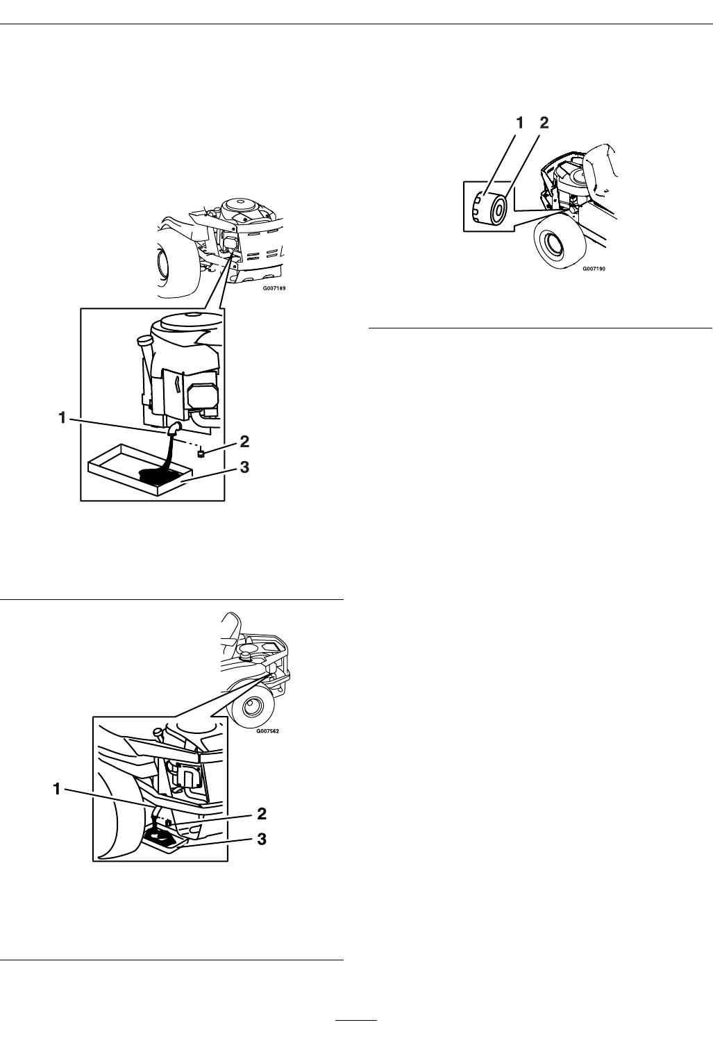
ServicingtheEngineOil
CheckingtheOilLevel
ServiceInterval:Beforeeachuseordaily
1.Parkthemachineonalevelsurface,disengage
thebladecontrolswitch,stoptheengine,engage
parkingbrake,andremovethekey.
2.Makesuretheengineisstopped,level,andiscool
sotheoilhashadtimetodrainintothesump.
3.Tokeepdirt,grassclippings,etc.,outof
theengine,cleantheareaaroundtheoilll
cap/dipstickbeforeremovingit.
4.Pullandremovetheoilllcap/dipstick;wipeoil
off.Reinsertthedipstickandpushrmlyinto
place(Figure25).
Figure25
1.Oildipstick3.Oillevel
2.Fillertube
5.Removethedipstickandchecktheoillevel.
Theoillevelshouldbeupto,butnotover,the
“F”markonthedipstick.
6.Ifthelevelislow ,addoilofthepropertype,upto
the“F”markonthedipstick.Alwayscheckthe
levelwiththedipstickbeforeaddingmoreoil.
Note:Topreventextensiveenginewearor
damage,alwaysmaintaintheproperoillevelin
thecrankcase.Neveroperatetheenginewiththe
oillevelbelowthe“L”markoroverthe“F”mark
onthedipstick.
ChangingtheOilandFilter
ServiceInterval:Aftertherst5hours
Every100hours/Yearly
(whichevercomesrst)
thereafter.
Changetheoilandlterwhiletheengineisstill
warm.Theoilwillowmorefreelyandcarryaway
moreimpurities.Makesuretheengineislevelwhen
lling,checking,orchangingtheoil.
1.Starttheengineandletitrununtilwarm.This
warmstheoilsoitdrainsbetter.
2.Disengagethebladecontrolswitchandmovethe
motioncontrolsoutwardtotheneutralposition
andengageparkingbrake.
32
Maintenance
3.Stoptheengine,removethekey,andwaitforall
movingpartstostopbeforeleavingtheoperating
position.
4.Cleantheareaaroundthedrainplugandonthe
machineframe.Placeapanunderneathmachine
directlybelowthedrainholeintheframeas
showninFigure26andFigure27.
Figure26
Briggs&Strattonengine
1.Oildrain3.Pan
2.Oildrainplug
Figure27
KohlerCommandengine
1.Oildrainhose3.Pan
2.Oildrainplug
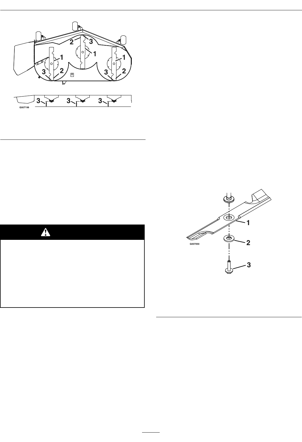
5.Removetheoildrainplug(Figure26and
Figure27).Removetheoilllcap/dipstick
(Figure25).
Figure28
1.Oillter2.Gasket
6.Besuretoallowampletimeforcomplete
drainage.
7.Removetheoldlterandwipeoffthemounting
pad(Figure28).
8.Whentheoilhasdrainedcompletely,installthe
oildrainplug.Tightentheplugto14N-m(125
in-lb)torque.Wipeupanyexcessoilontheframe
(Figure26andFigure27).
Note:Disposeoftheusedoilatarecycling
center.
9.Applyathinlmofcleanoiltotherubbergasket
onthenewlter.
10.Installthereplacementoilltertothemounting
pad.Turntheoillterclockwiseuntiltherubber
gasketcontactsthepad,thentightenthelteran
additional1/2to3/4turn(Figure28).
11.Slowlypourapproximately80%ofthespecied
oilintothellertube—useoilrecommendedin
theEngineOwner’sManual.
12.Installtheoilllcap/dipstickandpushrmly
intoplace.
13.Checktheoillevel(Figure25);refertoChecking
theOilLevel.
14.Slowlyaddadditionaloiltobringittothefull
mark.DoNotoverll.
15.Installtheoilllcap/dipstickandpushrmly
intoplace.
16.Starttheengineandcheckforleaks.
33
Maintenance
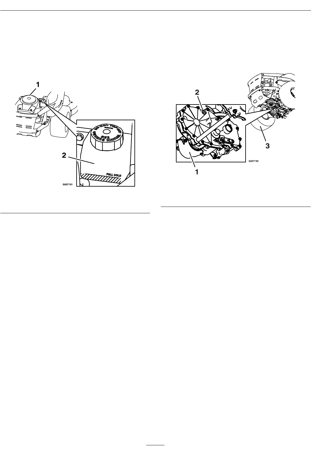
CheckingtheHydraulicOil
Level
ServiceInterval:Beforeeachuseordaily
CheckexpansiontankandifnecessaryaddMOBIL1
15W-50syntheticmotoroiltotheFULLCOLDline
Figure29
1.Engine2.Expansiontank
ChangetheHydraulic
SystemFilter
ServiceInterval:Aftertherst200hours
Note:UseonlyMOBIL115W-50Syntheticmotor
oil.
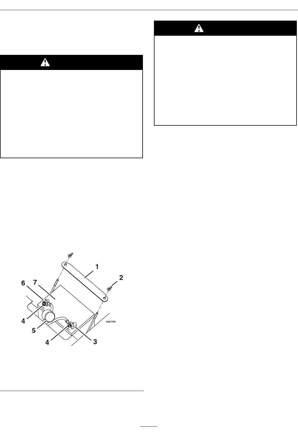
1.Stopengine,waitforallmovingpartstostop,and
allowenginetocool.Removekeyandengage
parkingbrake.
2.Locatethetwoltersunderthetransmissions.
Removelterguards.
3.Carefullycleanareaaroundlters.Itisimportant
thatnodirtorcontaminationenterhydraulic
system.
4.Unscrewlterstoremoveandallowoiltodrain
fromdrivesystem.
Important:Beforereinstallingnewlters,
applyathincoatofoilonthesurfaceofthe
ltersrubberseal.
Turntheltersclockwiseuntilrubberseal
contactsthelteradapterthentightenthelter
anadditional3/4to1fullturn.
5.Removetheventplugoneachtransmissionand
llthroughexpansionreservoir,whenoilcomes
outofventreinstallplug.Torqueplugsto180
in-lb(244N-m).Continuetoaddoiluntilit
reachestheFULLCOLDlineontheexpansion
reservoir.
Figure30
1.Oillter3.Leftreartire
2.Ventplug
6.Raisetherearofmachineupandsupportwith
jackstands(orequivalentsupport)justhigh
enoughtoallowdrivewheelstoturnfreely.
7.Startengineandmovethrottlecontrolaheadto
1/2throttleposition.Disengageparkingbrake.
A.Withthebypassvalveopenandtheengine
running,slowlymovethedirectionalcontrol
inbothforwardandreverse(5or6times).
B.Withthebypassvalveclosedandtheengine
running,slowlymovethedirectionalcontrol
inbothforwardandreversedirections(5to
6times).Checktheoillevel,andaddoilas
requiredafterstoppingtheengine.
C.ItmaybenecessarytorepeatstepsAand
Buntilalltheairiscompletelypurgedfrom
thesystem.Whenthetransaxleoperatesat
normalnoiselevelsandmovessmoothly
forwardandreverseatnormalspeeds,then
thetransaxleisconsideredpurged.
DoNotchangehydraulicsystemoil(exceptforwhat
canbedrainedwhenchanginglter),unlessitisfelt
theoilhasbeencontaminatedorbeenextremelyhot.
Changingoilunnecessarilycoulddamagehydraulic
systembyintroducingcontaminatesintothesystem.
34
Maintenance
ServicingtheSparkPlug
ServiceInterval:Every200hours/Every2
years(whichevercomes
rst)
Every500hours—Replace
thesparkplug.
Asstatedinthemaintenanceintervals,removethe
sparkplug,checkcondition,andresetthegapor
replacewithanewplugasnecessary.
ThesparkplugisRFIcompliant.Equivalentalternate
brandplugscanalsobeused.
Type:ChampionXC92YC(forBriggs&Stratton)
ChampionRC12YCorQC12Cmaybeusedifyour
areadoesnotrequirecompliancewithCanadian
ICES-002,ISO14982,orEN55012.
Type:ChampionRC12YC(forKohlerCommand)
AirGap:0.030inch(0.76mm)
RemovingtheSparkPlug
1.Disengagethebladecontrolswitch,movethe
motioncontrolsoutwardtotheparkposition,
stoptheengine,andremovethekey.
2.Pullthewireoffofthesparkplug(Figure31).
Cleanaroundthesparkplugtopreventdirtfrom
fallingintotheengineandpotentiallycausing
damage.
Note:Duetothedeeprecessaroundthespark
plug,blowingoutthecavitywithcompressedair
isusuallythemosteffectivemethodforcleaning.
Thesparkplugismostaccessiblewhenthe
blowerhousingisremovedforcleaning.
3.Removethesparkplugandmetalwasher.
Figure31
1.Sparkplugandwirelocation
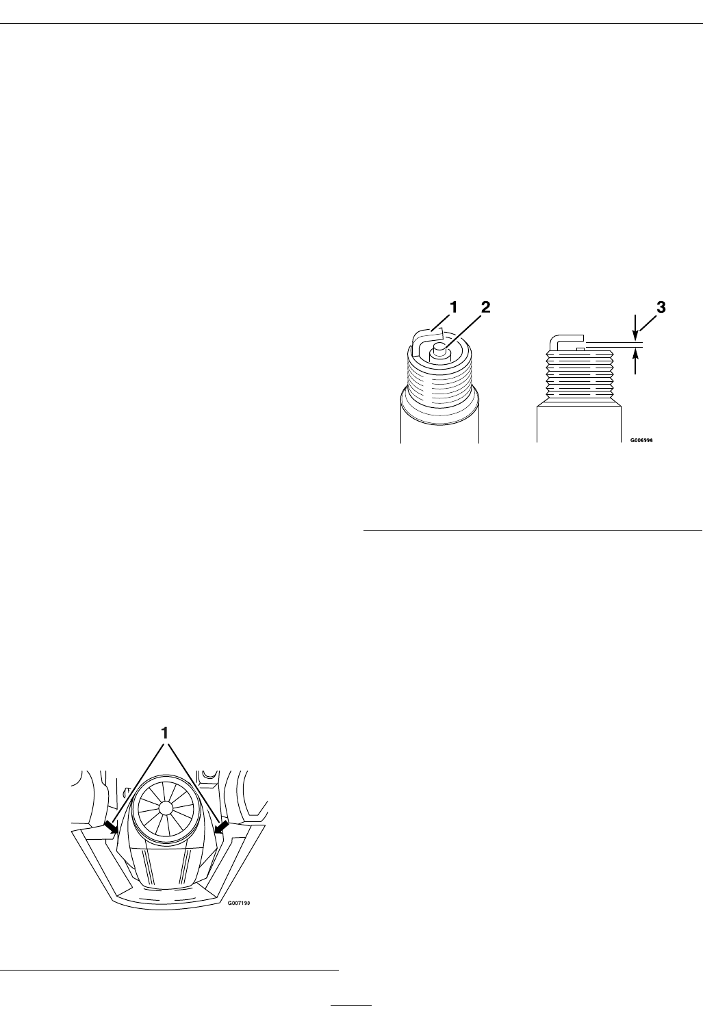
CheckingtheSparkPlug
1.Lookatthecenterofthesparkplug(Figure32).
Ifyouseelightbrownorgrayontheinsulator,the
engineisoperatingproperly.Ablackcoatingon
theinsulatorusuallymeanstheaircleanerisdirty.
Important:Nevercleanthesparkplug.
Alwaysreplacethesparkplugwhenithasa
blackcoating,wornelectrodes,anoilylm,
orcracks.
2.Checkthegapbetweenthecenterandside
electrodes(Figure32).Bendthesideelectrodeif
thegapisnotcorrect.
Figure32
1.Sideelectrode3.Airgap(nottoscale)
2.Centerelectrode
insulator
InstallingtheSparkPlug
1.Installthesparkplug.Makesurethattheairgap
issetcorrectly.
2.Tightenthesparkplugto15ft-lb(20N-m).
3.Pushthewireontothesparkplug(Figure31).
CleaningtheBlowerHousing
ServiceInterval:Every100hours/Yearly
(whichevercomesrst)
Moreoftenunderdirty
conditions.
Toensurepropercooling,makesurethegrassscreen,
coolingns,andotherexternalsurfacesoftheengine
arekeptcleanatalltimes.
1.Removetheblowerhousingandanyothercooling
shrouds.
2.Cleanthecoolingnsandexternalsurfacesas
necessary.
3.Makesurethecoolingshroudsarereinstalled
35
Maintenance
Important:Operatingtheenginewithablocked
grassscreen,dirtyorpluggedcoolingns,
and/orcoolingshroudsremoved,willcause
enginedamageduetooverheating.
FuelSystemMaintenance
ReplacingtheFuelFilter
ServiceInterval:Every100hours/Yearly
(whichevercomesrst)
DANGER
Incertainconditions,gasolineisextremely
ammableandhighlyexplosive.Areor
explosionfromgasolinecanburnyouand
othersandcandamageproperty.
•Performanyfuelrelatedmaintenance
whentheengineiscold.Dothisoutdoors
inanopenarea.Wipeupanygasoline
thatspills.
•Neversmokewhendraininggasoline,and
stayawayfromanopenameorwherea
sparkmayignitethegasolinefumes.
Neverinstalladirtylterifitisremovedfromthe
fuelline.
1.Parkthemachineonalevelsurfaceanddisengage
thebladecontrolswitch.
2.Movethemotioncontrolleversoutwardtothe
neutralposition,engageparkingbrake,stopthe
engine,removethekey,andwaitforallmoving
partstostopbeforeleavingtheoperatingposition.
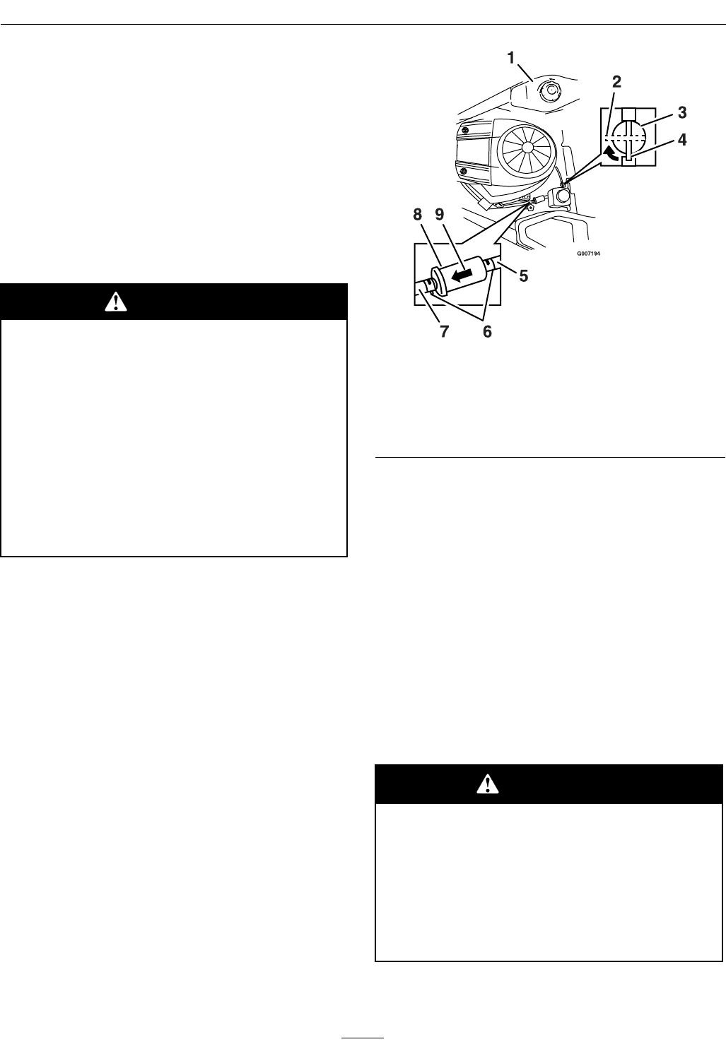
3.Thefuellterisinthefuellinebetweenthetank
andengine.
Figure33
1.Fueltank6.Hoseclamps
2.Fuelshutoffvalve—off7.Fuellinetoengine
3.Fuelshutoffvalve8.Filter
4.Fuelshutoffvalve—on9.Flowdirectionarrow
5.Fuellinefromtank
4.Turnfuelshutoffvalve90°to“off”position.
5.Squeezetheendsofthehoseclampstogetherand
slidethemawayfromthelter(Figure33).
6.Removethelterfromthefuellines.
7.Installanewlterwiththeowdirectionarrow
comingfromthefueltankandpointingtothe
engine.Movethehoseclampsclosetothelter
(Figure33)tosecureitinplace.
8.Turnfuelshutoffvalvebackto“on”position.
ElectricalSystem
Maintenance
WARNING
CALIFORNIA
Proposition65Warning
Batteryposts,terminals,andrelated
accessoriescontainleadandlead
compounds,chemicalsknowntotheStateof
Californiatocausecancerandreproductive
harm.Washhandsafterhandling.
36
Maintenance
ChargingtheBattery
RemovingtheBattery
WARNING
Batteryterminalsormetaltoolscouldshort
againstmetalmachinecomponentscausing
sparks.Sparkscancausethebatterygasses
toexplode,resultinginpersonalinjury.
•Whenremovingorinstallingthebattery,
DoNotallowthebatteryterminalsto
touchanymetalpartsofthemachine.
•DoNotallowmetaltoolstoshortbetween
thebatteryterminalsandmetalpartsof
themachine.
1.Parkthemachineonalevelsurfaceanddisengage
thebladecontrolswitch.
2.Movethemotioncontrolleversoutwardtothe
neutralposition,engageparkingbrakestopthe
engine,removethekey,andwaitforallmoving
partstostopbeforeleavingtheoperatingposition.
3.Raisetheseat.
4.Disconnectthenegative(black)groundcable
fromthebatterypost(Figure34).Retainall
fasteners.
Figure34
1.Batteryhold-down5.Terminalboot
2.Wingnut6.Positivebatterypost
3.Negativebatterypost7.Battery
4.Bolt,washer,andnut
WARNING
Incorrectbatterycableroutingcoulddamage
themachineandcablescausingsparks.
Sparkscancausethebatterygassesto
explode,resultinginpersonalinjury.
•Alwaysdisconnectthenegative(black)
batterycablebeforedisconnectingthe
positive(red)cable.
•Alwaysconnectthepositive(red)battery
cablebeforeconnectingthenegative
(black)cable.
5.Slidetherubbercoverupthepositive(red)cable.
Disconnectthepositive(red)cablefromthe
batterypost.Retainallfasteners.
6.Removethebatteryhold-down(Figure34)and
liftthebatteryfromthebatterytray.
ChargingtheBattery
1.Removethebatteryfromthechassis;referto
RemovingtheBattery.
2.Allowingbatteriestostandforanextendedperiod
withoutrechargingthemwillresultinreduced
performanceandservicelife.Topreserve
optimumbatteryperformanceandlife,recharge
batteriesinstoragewhentheopencircuitvoltage
dropsto12.4volts.
Note:Topreventdamageduetofreezing,
batteryshouldbefullychargedbeforeputting
awayforwinterstorage.
3.Checkthevoltageofthebatterywithadigital
voltmeter.Locatethevoltagereadingofthe
batteryinthetablebelowandchargethebattery
fortherecommendedtimeintervaltobringthe
chargeuptoafullchargeof12.6voltsorgreater.
Important:Makesurethenegativebattery
cablesaredisconnectedandthebattery
chargerusedforchargingthebatteryhasan
outputof16voltsand7ampsorlesstoavoid
damagingthebattery(seechartbelowfor
recommendedchargersettings).
37
Maintenance
Voltage
Reading
Percent
Charge
Maximum
Charger
Settings
Charging
Interval
12.6or
greater
100%16volts/7
amps
No
Charging
Required
12.4–12.675–100%16volts/7
amps
30Minutes
12.2–12.450–75%16volts/7
amps
1Hour
12.0–12.225–50%14.4volts/4
amps
2Hours
11.7–12.00–25%14.4volts/4
amps
3Hours
11.7orless0%14.4volts/2
amps
6Hoursor
More
4.Whenthebatteryisfullycharged,unplug
thechargerfromtheelectricaloutlet,then
disconnectthechargerleadsfromthebattery
posts(Figure35).
Figure35
1.Negativebatterypost3.Red(+)chargerlead
2.Black(-)chargerlead4.Positivebatterypost
Note:DoNotrunthemachinewiththebattery
disconnected,electricaldamagemayoccur.
InstallingtheBattery
1.Positionthebatteryinthetraywiththeterminal
poststowardtheoperatingposition(Figure34).
2.Installthepositive(red)batterycabletothe
positive(+)batteryterminalusingthefasteners
removedpreviously
3.Installthenegativebatterycabletothenegative
(-)batteryterminalusingthefastenersremoved
previously.
4.Slidetheredterminalbootontothepositive(red)
batterypost.
5.Securethebatterywiththehold-down(Figure34).
ServicingtheFusesand
Relay
Theelectricalsystemisprotectedbyfuses.Itrequires
nomaintenance;however,ifafuseblows,check
thecomponent/circuitforamalfunctionorshort.
Thereisalsoareplaceablerelay/snexttothefuse.
RefertoyourPartsmanualforcorrectreplacement
components.
FuseBlock:
•Mainfuse:25ampfuse,blade-type
•ChargeCircuit:20ampfuse,blade-type
•Auxiliarycircuit:15ampfuse,blade-type
•Diode:TVS
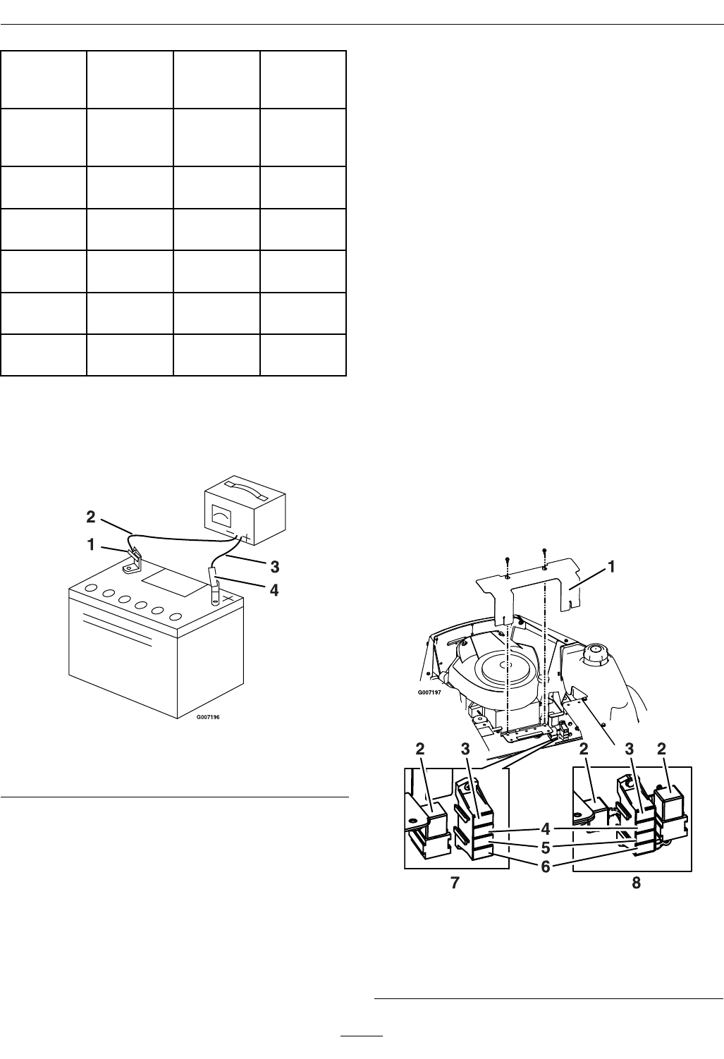
1.Raisetheseattogainaccesstothefuseholder
(Figure36).
Figure36
1.Cover5.Main–25amp
2.Relay6.Diode
3.Auxilliary–15amp7.Briggs&Strattonunit
4.Charge–20amp8.KohlerCommandunit
38
Maintenance
2.RemovecoverasshowninFigure36.
3.Toreplaceafuse,pulloutonthefusetoremoveit
DriveSystemMaintenance
CheckingtheTirePressure
ServiceInterval:Every25hours/Monthly
(whichevercomesrst)
Maintaintheairpressureinthefrontandreartiresas
specied.Uneventirepressurecancauseunevencut.
Checkthepressureatthevalvestem(Figure37).
Checkthetireswhentheyarecoldtogetthemost
accuratepressurereading.
RearTires:13psi(90kPa)
FrontTires(casterwheels):13psi(90kPa)
Figure37
1.Valvestem
MowerMaintenance
ServicingtheCuttingBlades
ServiceInterval:Beforeeachuseordaily
Maintainsharpbladesthroughoutthecuttingseason
becausesharpbladescutcleanlywithouttearingor
shreddingthegrassblades.Tearingandshredding
turnsgrassbrownattheedges,whichslowsgrowth
andincreasesthechanceofdisease.
Checkthecutterbladesdailyforsharpness,andfor
anywearordamage.Filedownanynicksandsharpen
thebladesasnecessary.Ifabladeisdamagedor
worn,replaceitimmediatelywithagenuineExmark
replacementblade.Forconvenientsharpeningand
replacement,youmaywanttokeepextrabladeson
hand.
WARNING
Awornordamagedbladecanbreak,anda
pieceofthebladecouldbethrownintothe
operator’sorbystander’sarea,resultingin
seriouspersonalinjuryordeath.
•Inspectthebladeperiodicallyforwearor
damage.
•Replaceawornordamagedblade.
BeforeInspectingorServicingthe
Blades
Parkthemachineonalevelsurface,disengagethe
bladecontrolswitch,andmovethemotioncontrol
leversoutwardtotheneutralpositionandengage
parkingbrake.Stoptheengine,removethekey,and
disconnectthesparkplugwire(s)fromthespark
plug(s).
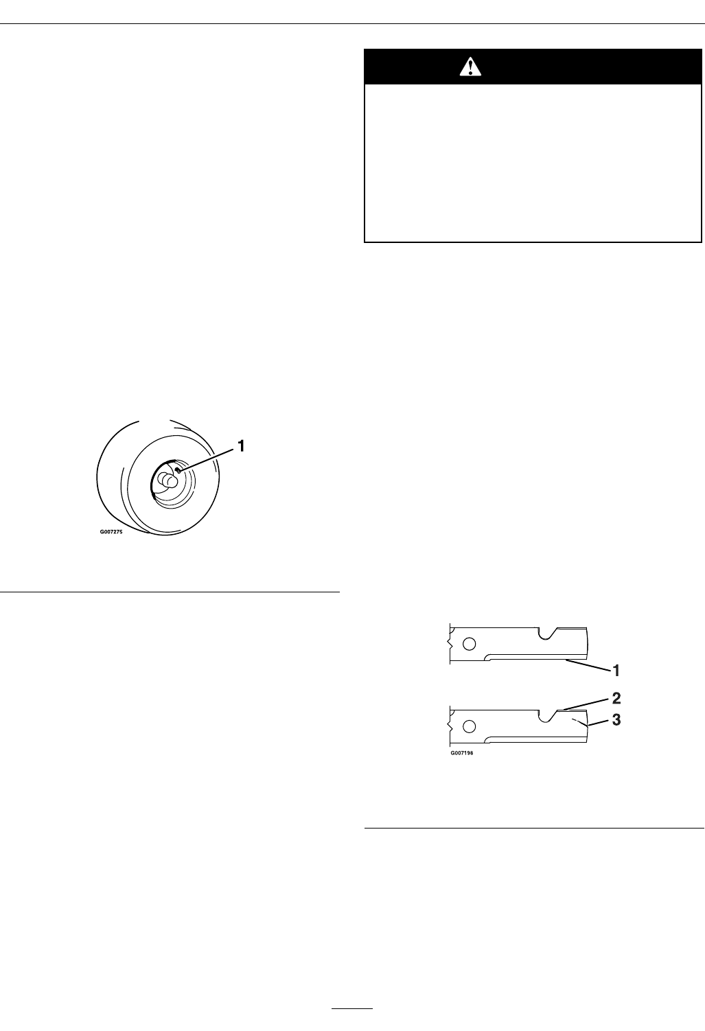
InspectingtheBlades
1.Inspectthecuttingedges(Figure38).Iftheedges
arenotsharporhavenicks,removeandsharpen
theblades;refertoSharpeningtheBlades.
2.Inspecttheblades,especiallythecurvedarea.If
younoticeanydamage,wear,oraslotformingin
thisarea(item3inFigure38),immediatelyinstall
anewblade.
Figure38
1.Cuttingedge3.Wear/slotforming
2.Curvedarea
CheckingforBentBlades
1.Rotatethebladesuntiltheendsfaceforward
andbackward(Figure39).Measurefromalevel
surfacetothecuttingedge,oftheblades.Note
thisdimension.
39
Maintenance
Figure39
1.Bladesfronttorear3.Measurehere
2.Outsidecuttingedges
2.Rotatetheoppositeendsofthebladesforward.
3.Measurefromalevelsurfacetothecuttingedge
ofthebladesatthesamepositionasinstep1.
Thedifferencebetweenthedimensionsobtained
insteps1and3mustnotexceed1/8inch(3
mm).Ifthisdimensionexceeds1/8inch(3mm),
thebladeisbentandmustbereplaced.Refer
toRemovingtheBladesandInstallingthe
Blades.
WARNING
Abladethatisbentordamagedcouldbreak
apartandcouldseriouslyinjureorkillyou
orbystanders.
•Alwaysreplacebentordamagedblade
withanewblade.
•Neverleorcreatesharpnotchesinthe
edgesorsurfacesofblade.
CheckingforLooseBladesor
DamagedSpringDiscWashers
1.Placeawrenchonthebladeboltandtorqueto
32-42ftlb(43-57N-m).
2.Withthewrenchstillonthebladebolt,holdthe
bladespindlestationaryandusingaragorthickly
paddedglove,trytorotatetheblade.Iftheblade
rotatesrelativetothespindleguardwithout
furthertighteningthebladebolt,thespring
discwasherhasbeenattenedordamagedand
theboltandwasherassemblymustbereplaced
(Figure40).RefertoRemovingtheBladesand
InstallingtheBlades.
3.Oncethebladehasbeenremoved,inspectthe
springdiscwasher.Ifthewasherappearstobe
damaged(thewashersurfacehasbeenmarred)
orattened,theboltandwasherassemblymust
bereplaced.
RemovingtheBlades
Thebladesmustbereplacedifasolidobjectishit,if
thebladeisoutofbalance,orthebladeisbent.To
ensureoptimumperformanceandcontinuedsafety
conformanceofthemachine,usegenuineExmark
replacementblades.Replacementbladesmadeby
othermanufacturersmayresultinanunsafemachine.
Holdthebladeendusingaragorthickly-padded
glove(orplaceawrenchonthetopsheavenut).
Removethebladeboltandwasherassembly,washer,
andbladefromthespindleshaft(Figure40).
Figure40
1.Blade
2.Washer
3.Boltandwasherassembly.Applylubricantto
threads—torqueto32-42ft-lb(43-57N-m).
SharpeningtheBlades
1.Usealetosharpenthecuttingedgeatbothends
oftheblade(Figure41).Maintaintheoriginal
angle.Thebladeretainsitsbalanceifthesame
amountofmaterialisremovedfrombothcutting
edges.
40
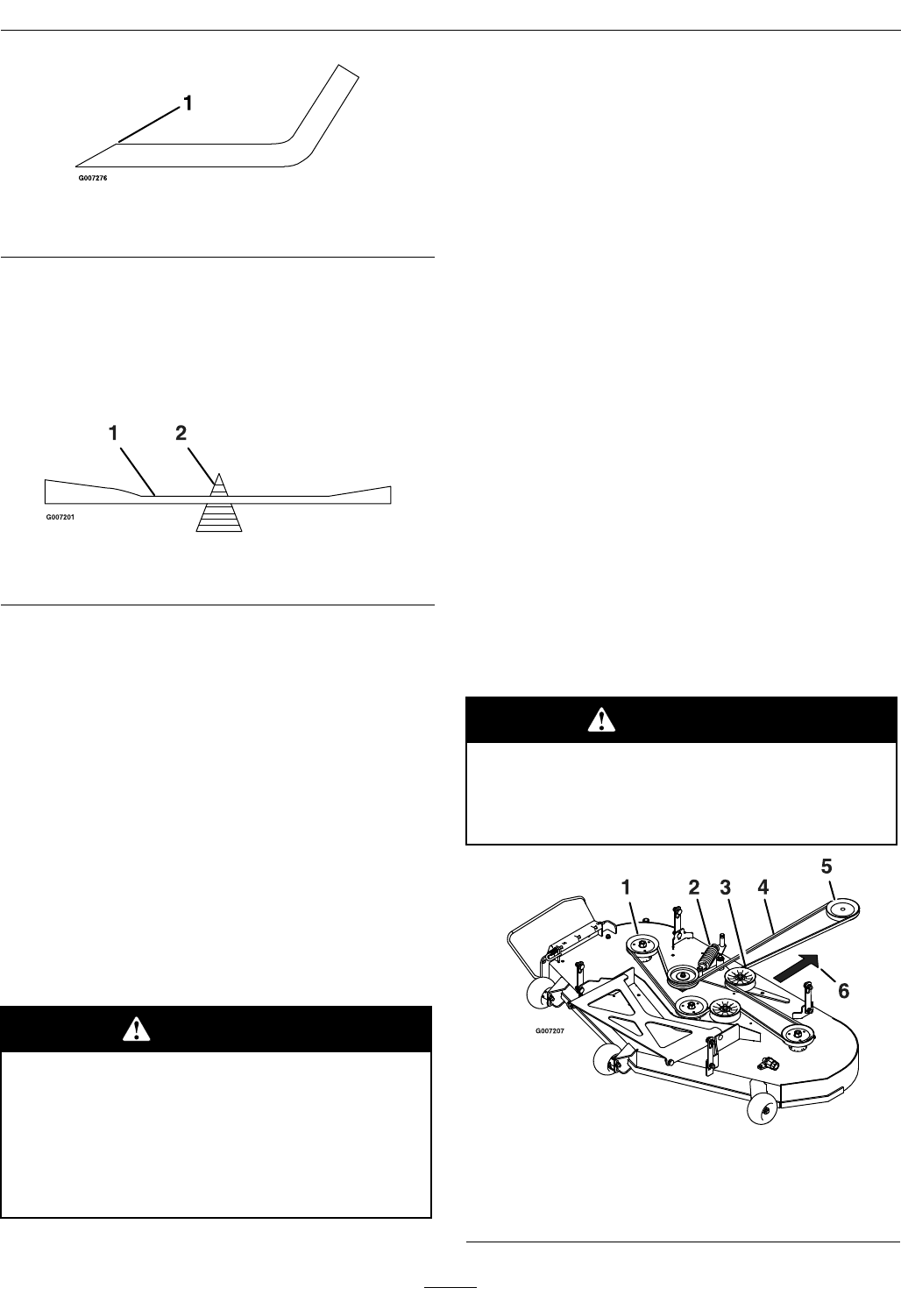
Maintenance
Figure41
1.Sharpenatoriginalangle
2.Checkthebalanceofthebladebyputtingitona
bladebalancer(Figure42).Ifthebladestaysina
horizontalposition,thebladeisbalancedandcan
beused.Ifthebladeisnotbalanced,lesome
metalofftheendofthesailareaonly(Figure42).
Repeatthisprocedureuntilthebladeisbalanced.
Figure42
1.Blade2.Balancer
InstallingtheBlades
1.Installthebladeontothespindleshaft(Figure40).
Important:Thecurvedpartoftheblade
mustbepointingupwardtowardtheinsideof
themowertoensurepropercutting.
2.Holdthebladeendusingaragorthickly-padded
glove(orplaceawrenchonthetopsheavenut).
Applylubricanttothethreadsofthebladebolt
asneededtopreventseizing.Copperbased
anti-seizeispreferable.Greaseisanacceptable
substitute.Installthewasherandbladeboltand
washerassembly.
3.Torquethebladeboltto32-42ft-lb(43-57N-m).
WARNING
Incorrectinstallationofthebladeor
componentsusedtoretainthebladecause
thebladetocomelooseandcouldseriously
injureorkillyouorbystanders.
AlwaysinstalltheoriginalExmarkblades,
washersandbladeboltsasshown.
MowerBeltMaintenance
InspectingtheBelts
ServiceInterval:Every25hours
Checkthebeltsforcracks,frayededges,burnmarks,
oranyotherdamage.Replacedamagedbelts.
ReplacingtheMowerBelt
Squealingwhenthebeltisrotating,bladesslipping
whencuttinggrass,frayedbeltedges,burnmarks,
andcracksaresignsofawornmowerbelt.Replace
themowerbeltifanyoftheseconditionsareevident.
1.Parkthemachineonalevelsurfaceanddisengage
thebladecontrolswitch.
2.Movethemotioncontrolleversoutwardtothe
neutralposition,engageparkingbrake,stopthe
engine,removethekey,andwaitforallmoving
partstostopbeforeleavingtheoperatingposition.
3.Settheheight-of-cutat1-1/2inch(38mm).
4.Removethebeltcoversovertheoutsidespindles.
5.Pulltheidlerpulleyinthedirectionshownin
Figure48androllthebeltoffofthepulleys.
WARNING
Thespringisundertensionwheninstalled
andcancausepersonalinjury.
Becarefulwhenremovingthebelt.
Figure43
1.Outsidepuley4.Mowerbelt
2.Spring5.Enginepulley
3.Idlerpulley6.Pullidlerinthisdirection.
41
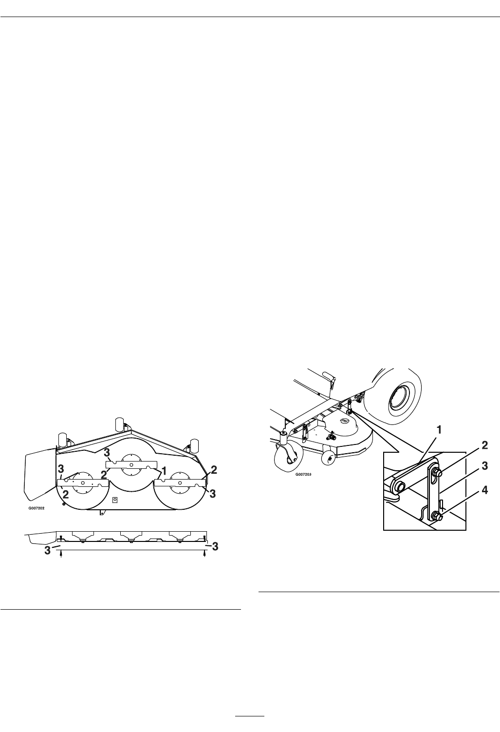
Maintenance
6.Routethenewbeltaroundtheenginepulleyand
mowerpulleys.
7.Pulltheidlerpulleyinthedirectionshownin
Figure43androutethebeltontotheidlerpulley.
8.Installthebeltcoversovertheoutsidespindles.
LevelingtheMowerDeck
Themowerbladesmustbelevelfromsidetoside.
Checktheside-to-sidelevelanytimeyouinstallthe
mowerorwhenyouseeanunevencutonyourlawn.
1.Parkthemachineonalevelsurfaceanddisengage
thebladecontrolswitch.
2.Movethemotioncontrolleversoutwardtothe
neutralposition,engageparkingbrake,stopthe
engine,removethekey,andwaitforallmoving
partstostopbeforeleavingtheoperatingposition.
3.Checktheairpressureofallfourtires.Ifneeded,
adjusttotherecommendedination;referto
CheckingtheTirePressureinDriveSystem
Maintenancesection.Ifeitheroneisoutofrange
thenfollowadjustmentprocedure.
4.Carefullyrotatethebladessidetoside.
5.Measurebetweentheoutsidecuttingedgesand
theatsurface(Figure44).Ifbothmeasurements
arenotwithin3/16inch(5mm),anadjustmentis
required;continuewiththisprocedure.
Figure44
1.Bladessidetoside3.Measurehere
2.Outsidecuttingedges
6.Checkthefront-to-rearbladelevelanytimeyou
installthemower.Ifthefrontbladetipisnot
1/16-5/16inch(1.6-7.9mm)lowerthantherear
bladetip,adjustthebladelevel.Ifmeasurements
fromsteps5or6areoutofrange,thenfollow
AdjustingtheBladeSlope.
7.Setanti-scalprollerstotopholesorremove
completelyforthisadjustment.
8.Settheheight-of-cutlevertothe3inch(76mm)
position.Placetwo21/2inch(6.35cm)thick
blocksundertherearedgeofthecuttingdeck
skirt;oneoneachsideofthecuttingdeck.Place
two25/16inch(5.89cm)blocksundereachside
ofthefrontedgeofthedeck,butnotunderthe
anti-scalprollerbrackets.
9.Carefullyrotatethebladessidetoside(Figure44).
10.Loosenthelevelingadjustlockingnuts(item4)
onallfourcornerssothatthedeckissitting
securelyonallfourblocks.Makesurethatthe
deckhangersareallthewaydown(atthetopof
theslot)andthedeckliftfootleverispushedback
againstthestop,thentightenthefourleveling
adjustlockingnuts
11.Recheckthatblockstjustsnuglyunderthedeck
skirt.Makesureallattachmentboltsaretight
12.Continuelevelingthedeckbycheckingthe
front-to-rearbladeslope;refertoAdjustingthe
Front-to-RearBladeSlope.
13.Recheckbladesforlevelnessandrepeatdeck
levelingprocedureifnecessary.
Figure45
1.Deckliftarm3.Deckhanger
2.Floatretainingnut4.Levelingadjustlocking
nut
AdjustingtheBladeSlope
1.Checkthefront-to-rearbladelevelanytimeyou
installthemower.Ifthefrontbladetipisnot
1/16-5/16inch(1.6-7.9mm)lowerthantherear
bladetip,adjustthebladelevelusingthefollowing
instructions:
42
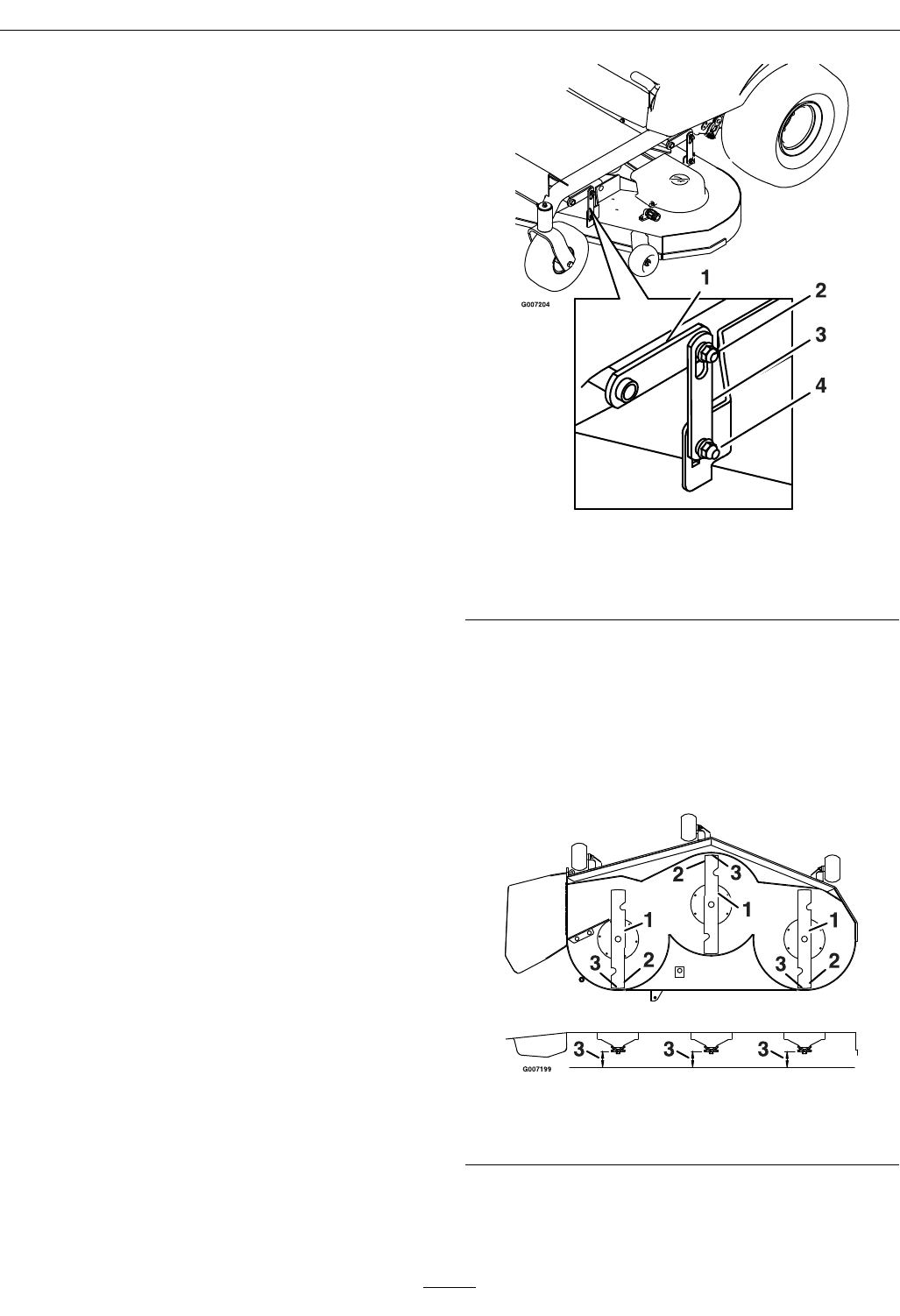
Maintenance
2.Parkthemachineonalevelsurfaceanddisengage
thebladecontrolswitch.
3.Movethemotioncontrolleversoutwardto
theneutralposition,engagetheparkingbrake,
stoptheengine,removethekey,andwaitforall
movingpartstostopbeforeleavingtheoperating
position.
4.Checktheairpressureofallfourtires.Ifneeded,
adjusttotherecommendedination;referto
CheckingtheTirePressureinDriveSystem
Maintenancesection.
5.Checkandadjusttheside-to-sidebladelevelifyou
havenotcheckedthesetting;refertoLeveling
theMower.
6.Settheheight-of-cutlevertothe3inch(76mm)
position.Placetwo21/2inch(6.35cm)thick
blocksundertherearedgeofthecuttingdeck
skirt;oneoneachsideofthecuttingdeck.Place
two25/16inch(5.89cm)blocksundereachside
ofthefrontedgeofthedeck,butnotunderthe
anti-scalprollerbrackets.
7.Loosenthelevelingadjustlockingnuts(item4)
onallfourcornerssothatthedeckissitting
securelyonallfourblocks.Makesurethatthe
deckhangersareallthewaydown(atthetopof
theslot)andthedeckliftfootleverispushedback
againstthestop,thentightenthefourleveling
adjustlockingnuts(Figure46).
Figure46
1.Deckliftarm3.Deckhanger
2.Floatretainingnut4.Levelingadjustlocking
nut
8.Carefullyrotatethebladessotheyarefacingfront
torear(Figure47).
9.Measurefromthetipofthefrontbladetotheat
surfaceandthetipoftherearbladetotheat
surface(Figure47).Ifthefrontbladetipisnot
1/16-5/16inch(1.6-7.9mm)lowerthantherear
bladetip,adjustthefrontdeckhanger.
Figure47
1.Bladesfronttorear3.Measurehere
2.Outsidecuttingedges
10.Whenthefront-to-rearbladeslopeiscorrect
checktheside-to-sidelevelofthemoweragain;
refertoLevelingtheMower.
43
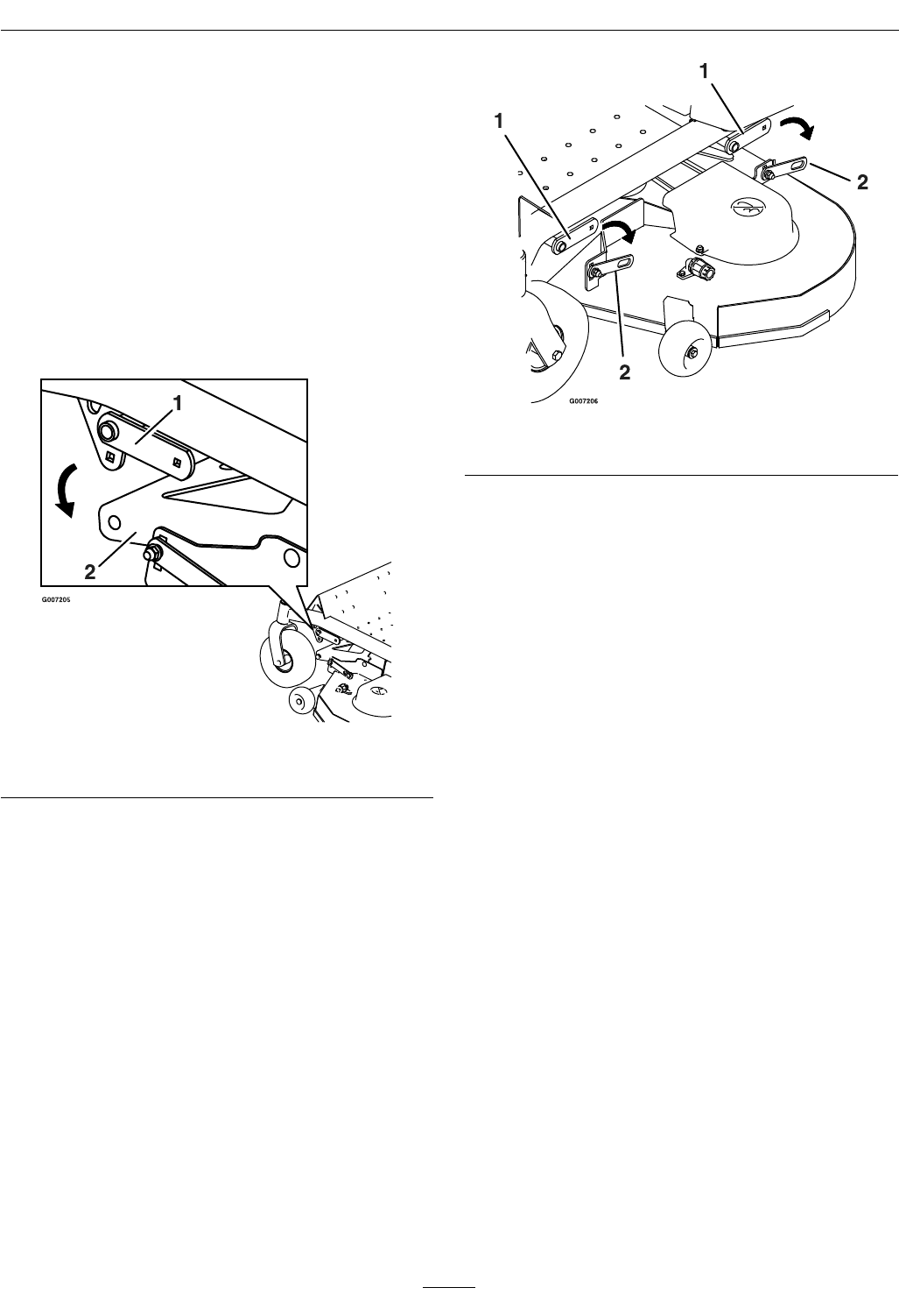
Maintenance
RemovingtheMowerDeck
1.Parkthemachineonalevelsurfaceanddisengage
thebladecontrolswitch
2.Movethemotioncontrolleversoutwardtothe
neutralposition,engageparkingbrake,stopthe
engine,removethekey,andwaitforallmoving
partstostopbeforeleavingtheoperatingposition.
3.Placeblocksunderdeckforsupport.Lowerthe
height-of-cutlevertothelowestposition.
4.Removethehardwarefromthedeckhangerand
deckliftarmonbothsidesofthedeck(Figure48).
Figure48
1.Deckliftarm2.Deckhanger
5.Removethenut,bolt,andpivotbushingfromthe
deckstrut(Figure48).Carefullylowerthefront
ofthemowerdecktotheground(Figure49).
Figure49
1.Deckliftarm2.Deckstrut
6.Slidethemowerrearwardtoremovethemower
beltfromtheenginepulley.
7.Slidethemoweroutfromunderneaththe
machine.
Note:Retainallpartsforfutureinstallation.
InstallingtheMowerDeck
1.Parkthemachineonalevelsurfaceanddisengage
thebladecontrolswitch.
2.Movethemotioncontrolleversoutwardtothe
neutralposition,engageparkingbrake,stopthe
engine,removethekey,andwaitforallmoving
partstostopbeforeleavingtheoperatingposition.
3.Slidethemowerunderthemachine.
4.Lowertheheight-of-cutlevertothelowest
position.
5.Usetheexistinghardwaretoattachthereardeck
strutofthemowertothedeckliftarm(Figure49).
6.Attachthehardwarefromthedeckhangerand
deckliftarmonbothsidesofthedeck(Figure48).
7.Installthemowerbeltontotheenginepulley;
refertoReplacingtheMowerBelt.
44
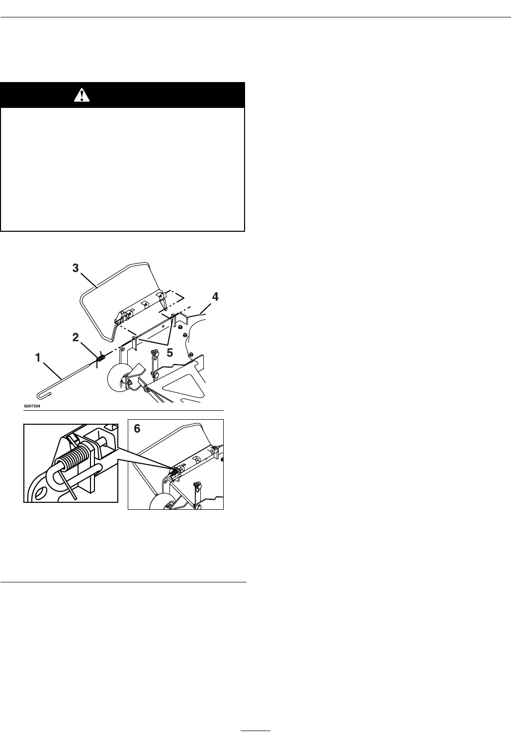
Maintenance
ReplacingtheDischarge
Deector
DANGER
Anuncovereddischargeopeningcouldallow
thelawnmowertothrowobjectsinthe
operator’sorbystander’sdirectionandresult
inseriousinjury.Also,contactwiththeblade
couldoccur.
Neveroperatethelawnmowerunlessyou
installamulchplate,dischargedeector,or
grasscollectionsystem.
1.LocateitemsshowninFigure50.
Figure50
1.Rod4.Mowerdeck
2.Spring5.Dischargedeector
bracket
3.Dischargedeector6.Assembledview
2.Slidetherodoutoftheshortstand-off,spring,
anddischargedeector.Removethedamagedor
worndischargedeector.
3.Installnewdischargedeector.
4.Orientthespringsothattheshortlegpoints
towardsthedischargedeectorandthelongerleg
pointstowardsthedeckasshowninFigure50.
Placespringonrodandsliderod,straightend,
throughthefrontdischargedeectorbracket,
dischargedeector,andreardeectorbracket.
5.Makesurethatthespringandrodareinstalled
sothattherodisretainedfromslidingout
bythefrontbracketandthespringholdsthe
dischargedeectorinthedownposition.Referto
(Figure50)forproperorientation.
Important:Thedischargedeectormustbe
springloadedinthedownposition.Liftthe
deectoruptotestthatitsnapstothefull
downposition.
45
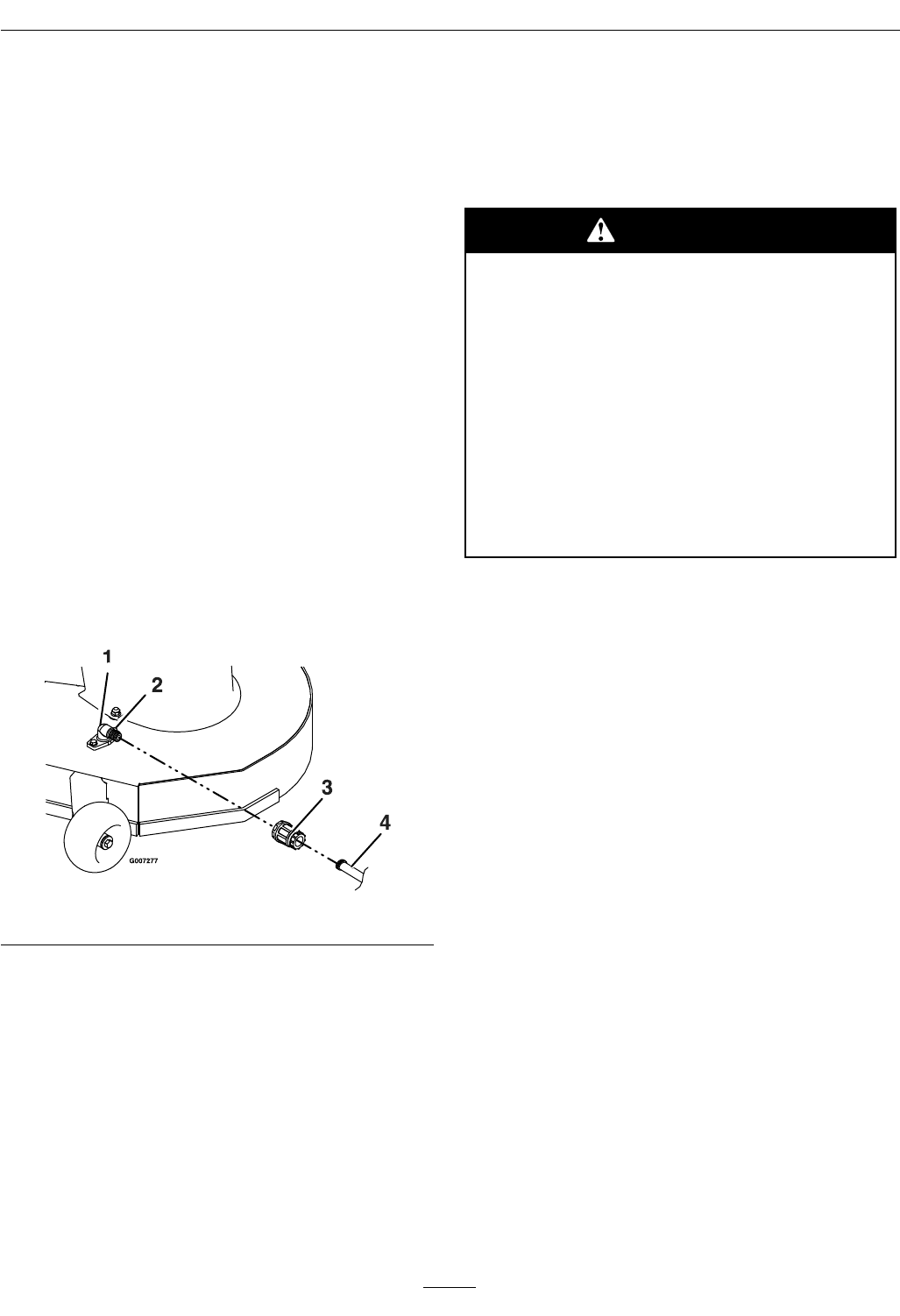
Maintenance
Cleaning
WashingtheUndersideof
theMower
ServiceInterval:Beforeeachuseordaily
Aftereachuse,washtheundersideofthemowerto
preventgrassbuildupforimprovedmulchactionand
clippingdispersal.
1.Parkthemachineonalevelsurfaceanddisengage
thebladecontrolswitch.
2.Movethemotioncontrolleversoutwardtothe
neutralposition,engageparkingbrake,stopthe
engine,removethekey,andwaitforallmoving
partstostopbeforeleavingtheoperatingposition.
3.Attachthehosecouplingtotheendofthemower
washouttting,andturnthewateronhigh
(Figure51).
Note:Spreadpetroleumjellyonthewashout
ttingO-ringtomakethecouplingslideoneasier
andprotecttheO-ring.
Figure51
4.Lowerthemowertothelowestheight-of-cut.
5.Sitontheseatandstarttheengine.Engagethe
bladecontrolswitchandletthemowerrunfor
onetothreeminutes.
6.Disengagethebladecontrolswitch,stopthe
engine,andremovetheignitionkey.Waitforall
movingpartstostop.
7.Turnthewateroffandremovethecouplingfrom
thewashouttting.
Note:Ifthemowerisnotcleanafterone
washing,soakitandletitstandfor30minutes.
Thenrepeattheprocess.
8.Runthemoweragainforonetothreeminutes
toremoveexcesswater.
WARNING
Abrokenormissingwashoutttingcould
exposeyouandotherstothrownobjectsor
bladecontact.Contactwithbladeorthrown
debriscancauseinjuryordeath.
•Replacebrokenormissingwashout
ttingimmediately,beforeusingmower
again.
•Pluganyhole(s)inmowerwithboltsand
locknuts.
•Neverputyourhandsorfeetunderthe
mowerorthroughopeningsinthemower.
46

Storage
Storage
CleaningandStorage
1.Disengagethebladecontrolswitch,movethe
motioncontrolsoutwardtotheneutralposition,
engageparkingbrake,stoptheengine,and
removethekey.
2.Removegrassclippings,dirt,andgrimefromthe
externalpartsoftheentiremachine,especiallythe
engine.Cleandirtandchafffromtheoutsideof
theenginecylinderheadnsandblowerhousing.
Important:Youcanwashthemachinewith
milddetergentandwater.DoNotpressure
washthemachine.Avoidexcessiveuseof
water,especiallynearthecontrolpanel,
engine,hydraulicpumps,andmotors.
3.Servicetheaircleaner;refertoServicingtheAir
CleanerinEngineMaintenancesection.
4.Greaseandoilthemachine;refertoLubrication
section.
5.Changethecrankcaseoilandlter;refer
toServicingtheEngineOilinEngine
Maintenancesection.
6.Checkthetirepressure;refertoCheckingthe
TirePressureinDriveSystemMaintenance
section.
7.Chargethebattery;refertoServicingthe
BatteryinElectricalSystemMaintenancesection.
8.Checktheconditionoftheblades;referto
ServicingtheCuttingBladesinMower
Maintenancesection.
9.Preparethemachineforstoragewhennon-use
occursover30days.Preparethemachinefor
storageasfollows.
A.Addapetroleumbasedstabilizer/conditioner
tothefuelinthetank.Followthemixing
instructionsfromthestabilizermanufacturer.
DoNotuseanalcoholbasedstabilizer
(ethanolormethanol).
Note:Afuelstabilizer/conditionerismost
effectivewhenmixedwithfreshgasolineand
usedatalltimes.
B.Runtheenginetodistributetheconditioned
fuelthroughthefuelsystem(5minutes).
C.Stoptheengine,allowittocool,anddrainthe
fueltank;refertoDrainingtheFuelTankin
FuelSystemMaintenancesection.
D.Restarttheengineandrunituntilitstops.
E.Choketheengine.Startandruntheengine
untilitwillnotstart.
F.Disposeoffuelproperly.Recycleasperlocal
codes.
Important:DoNotstore
stabilizer/conditionedgasolineover
30days.
10.Removethesparkplug(s)andcheckitscondition;
refertoServicingtheSparkPluginEngine
Maintenancesection.Withthesparkplug(s)
removedfromtheengine,pourtwotablespoons
ofengineoilintothesparkplughole.Usethe
startertocranktheengineanddistributetheoil
insidethecylinder.Installthesparkplug(s).Do
Notinstallthewireonthesparkplug(s).
11.Cleananydirtandchafffromthetopofthe
mower.
12.Scrapeanyheavybuildupofgrassanddirtfrom
theundersideofthemower,thenwashthemower
withagardenhose.
13.Checktheconditionofthedriveandmowerbelts.
14.Checkandtightenallbolts,nuts,andscrews.
Repairorreplaceanypartthatiswornor
damaged.
15.Paintallscratchedorbaremetalsurfaces.Paintis
availablefromyourAuthorizedServiceDealer.
16.Storethemachineinaclean,drygarageorstorage
area.Removethekeyfromtheignitionswitch
andkeepitinamemorableplace.Coverthe
machinetoprotectitandkeepitclean.
47

Troubleshooting
Troubleshooting
Important:Itisessentialthatalloperatorsafetymechanismsbeconnectedandinproperoperating
conditionpriortomoweruse.
Whenaproblemoccurs,DoNotoverlookthesimplecauses.Forexample:startingproblemscouldbe
causedbyanemptyfueltank.
Thefollowingtablelistssomeofthecommoncausesoftrouble.DoNotattempttoserviceorreplacemajor
itemsoranyitemsthatcallforspecialtimingofadjustmentsprocedures(suchasvalves,governor,etc.).Have
thisworkdonebyyourEngineServiceDealer.
Note:WhendisconnectingelectricalconnectorsDONOTpullonthewirestoseparatetheconnectors.
ProblemPossibleCauseCorrectiveAction
1.Theengineloadisexcessive.1.Reducegroundspeed.
2.Theoillevelinthecrankcaseislow .2.Addoiltothecrankcase.
3.Thecoolingnsandairpassagesunder
theengineblowerhousingareplugged.
3.Removetheobstructionfromthecooling
nsandairpassages.
4.Theaircleanerisdirty.4.Cleanorreplacetheaircleanerelement.
Theengineoverheats.
5.Dirt,water,orstalefuelisinfuelsystem.5.ContactanAuthorizedServiceDealer.
1.Thebladecontrolswitchisengaged.1.Movethebladecontrolswitchto
Disengaged.
2.Themotioncontrolleversarenotinthe
parkposition.
2.Movethemotioncontrolleversoutward
totheparkposition.
3.Theoperatorisnotseated.3.Sitontheseat.
4.Thebatteryisdead.4.Chargethebattery.
5.Theelectricalconnectionsarecorroded
orloose.
5.Checktheelectricalconnectionsforgood
contact.
6.Afuseisblown.6.Replacethefuse.
Thestarterdoesnotcrank
7.Arelayorswitchisdamaged.7.ContactanAuthorizedServiceDealer.
1.Fueltankisempty.1.Fillthefueltank.
2.Thechokeisnoton.2.MovethechokelevertoOn.
3.Theaircleanerisdirty.3.Cleanorreplacetheaircleanerelement.
4.Thesparkplugwire(s)islooseor
disconnected.
4.Installthewire(s)onthesparkplug.
5.Thesparkplug(s)ispitted,fouled,orthe
gapisincorrect.
5.Installanew,correctlygappedspark
plug(s).
6.Thereisdirtinfuellter.6.Replacethefuellter.
7.Dirt,water,orstalefuelisinthefuel
system.
7.ContactanAuthorizedServiceDealer.
8.Thereisincorrectfuelinthefueltank.8.Drainthetankandreplacethefuelwith
thepropertype.
Enginewillnotstart,startshard,orfailsto
keeprunning
9.Theoillevelinthecrankcaseislow .9.Addoiltothecrankcase.
48

Troubleshooting
ProblemPossibleCauseCorrectiveAction
1.Engineloadisexcessive.1.Reducethegroundspeed.
2.Aircleanerisdirty.2.Cleanorreplacetheaircleanerelement.
3.Oillevelinthecrankcaseislow .3.Addoiltothecrankcase.
4.Coolingnsandairpassagesforthe
engineareplugged.
4.Removetheobstructionsfromthecooling
nsandairpassages.
5.Thesparkplug(s)ispitted,fouled,orthe
gapisincorrect.
5.Installanew,correctlygappedspark
plug(s).
6.Ventholeinthefuelcapisclosed.6.Opentheventinthefuelcap.
7.Dirtinfuellter.7.Replacethefuellter.
8.Dirt,water,orstalefuelisinthefuel
system.
8.ContactanAuthorizedServiceDealer.
Enginelosespower
9.Thereisincorrectfuelinthefueltank.9.Drainthetankandreplacethefuelwith
thepropertype.
1.Thedrivebeltsareworn,loose,orbroken.1.ContactanAuthorizedServiceDealer.
2.Thedrivebeltsareoffofthepulleys.2.ContactanAuthorizedServiceDealer.
Themachinedoesnotdrive.
3.Thedriveisinbypassmode.3.Takemachineoutofbypassmode.Refer
toPushingtheMachinebyHand
section.
1.Enginemountingboltsareloose.1.Tightentheenginemountingbolts.
2.Looseenginepulley,idlerpulley,orblade
pulley.
2.Tightentheappropriatepulley.
3.Enginepulleyisdamaged.3.ContactanAuthorizedServiceDealer.
4.Cuttingblade(s)is/arebentorunbalanced.4.Installnewcuttingblade(s).
5.Bladeisloose.5.Tightentheblademountingboltand
inspectthebladespringdiscwasherfor
damage(SeeServicingtheCutting
Bladessection).
Abnormalvibration
6.Bladespindleisbent.6.ContactanAuthorizedServiceDealer.
1.Blade(s)notsharp.1.Sharpentheblade(s).
2.Cuttingblade(s)is/arebent.2.Installnewcuttingblade(s).
3.Abladeisloose.3.Tightentheblademountingboltand
inspectthebladespringdiscwasherfor
damage(SeeServicingtheCutting
Bladessection).
4.Mowerdeckisnotlevel.4.Levelmowerdeckfromside-to-sideand
front-to-rear.
5.Ananti-scalpwheelisnotsetcorrectly5.Adjusttheanti-scalpwheelheight.
6.Undersideofmowerisdirty.6.Cleantheundersideofthemower.
7.Tirepressureindrivetiresnotcorrect.7.Adjusttirepressure.
Unevencuttingheight.
8.Bladespindlebent.8.ContactanAuthorizedServiceDealer.
1.Drivebeltisworn,looseorbroken.1.Installnewdrivebelt.
2.Drivebeltisoffpulley.2.Installdrivebeltandcheckadjusting
shaftsandbeltguidesforcorrectposition.
3.Deckbeltisworn,looseorbroken.3.Installnewdeckbelt.
4.Deckbeltisoffpulley.4.Installdeckpulleyandchecktheidler
pulley,idlerarmandspringforcorrect
positionandfunction.
Bladesdonotrotate.
5.Themowerbeltisworn,loose,orbroken.5.Installanewmowerbelt.
49
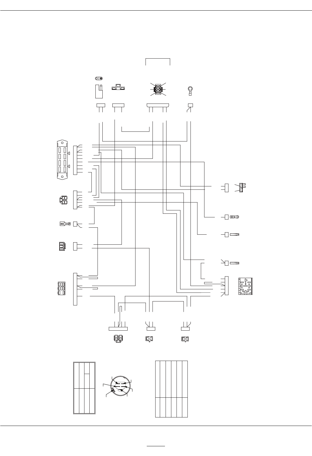
Schematics
Schematics
ElectricalDiagram—Briggs&Stratton
TERMINAL I
TERMINAL S
TERMINAL X
TERMINAL Y
TERMINAL B
TERMINAL A
3. START
POSITION
1. OFF
2. RUN
B + I + S
CIRCUIT "MAKE"
X + Y
NONE
B + I + A
IGNITION SWITCH
TERMINAL CONNECTIONS
TERMINAL A VOLTAGE REGULATOR
TERMINAL B BATTERY
TERMINAL I HOUR METER, PTO SWITCH
TERMINAL S SOLENOID
TERMINAL X SEAT SWITCH, ACCESSORIES
TERMINAL Y HOUR METER, PTO SWITCH
CONNECTORS VIEWED FROM WIRE END
NOTE:
FUEL SOLENOID
BRAKE
SWITCH
RH
MOTION
CONTROL
LH
MOTION
CONTROL
STARTER LOCKOUT
& KILL RELAY
START
SOLENOID
GROUND
START
SOLENOID
SIGNAL
START
SOLENOID
B+ PTO
CLUTCH
GROUND
ALTERNATOR
OIL SWITCH
HOUR METER
ACCESSORIES
FUSE BLOCK
IGNITION SWITCH
SEAT SWITCH
PTO SWITCH
ORANGE
ORANGE
ORANGE
ORANGE
ORANGE
DARK GREEN
DARK GREEN
BROWN
BROWN
VIOLET
VIOLET
VIOLET
RED
RED
RED
Y S X A B
I
ORANGE
BLACK
PINK
LIGHT BLUE
LIGHT BLUE
PINK
PINK
PINK
PINK
PINK
PINK
DARK BLUE
RED
VIOLET
YELLOW
WHITE
BLACK
BLACK
DARK GREEN
DARK GREEN
DARK GREEN
BROWN
GRAY
BROWN
YELLOW
YELLOW
YELLOW
GREEN
GREEN
VIOLET
VIOLET
VIOLET
VIOLET
GRAY
VILOET
MAGNETO
ENGINE
BROWN
DARK GREEN
2
3
5
4
1
2
1
2
1
42135 1 1 1 AB
1
1
2
3
3 5 7 4 6 8 1 2
2 5 1 3 4
1
2 1
987654321
B
A
5
1
4
6
3
2
1
2
3
4
5
2
1
2 1
4
9 8 7
3
1
2
2
1
1
2
3
4
5
BA
456
123
1
2
3
A
B
1
2
3
4
5
6
7
8
1
2
3
4
5
BLACK
BLACK
YELLOW
WHITE
YELLOW
DARK BLUE
G007525
50
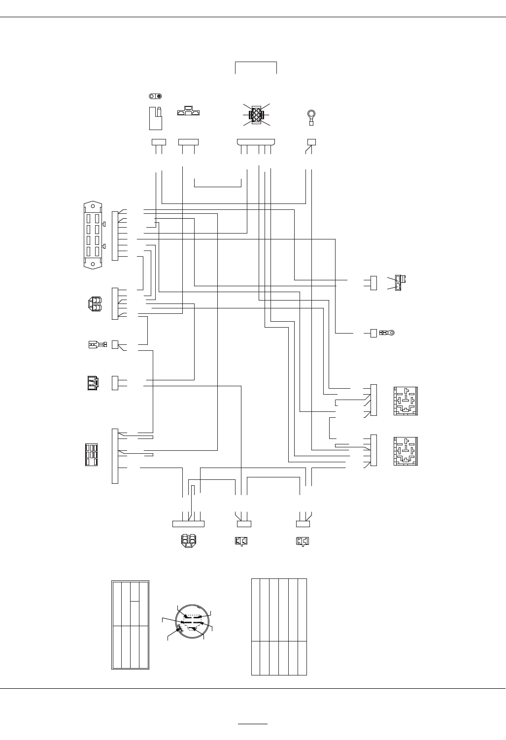
Schematics
ElectricalDiagram—KohlerCommand
TERMINAL I
TERMINAL S
TERMINAL X
TERMINAL Y
TERMINAL B
TERMINAL A
3. START
POSITION
1. OFF
2. RUN
B + I + S
CIRCUIT "MAKE"
X + Y
NONE
B + I + A
IGNITION SWITCH
TERMINAL CONNECTIONS
TERMINAL A VOLTAGE REGULATOR
TERMINAL B BATTERY
TERMINAL I HOUR METER, PTO SWITCH
TERMINAL S SOLENOID
TERMINAL X SEAT SWITCH, ACCESSORIES
TERMINAL Y HOUR METER, PTO SWITCH
CONNECTORS VIEWED FROM WIRE END
NOTE:
FUEL SOLENOID
BRAKE
SWITCH
RH
MOTION
CONTROL
LH
MOTION
CONTROL
KILL RELAY
START
SOLENOID
B+ PTO
CLUTCH
GROUND
ALTERNATOR
OIL SWITCH
HOUR METER
ACCESSORIES
FUSE BLOCK
IGNITION SWITCH
SEAT SWITCH
PTO SWITCH
ORANGE
ORANGE
ORANGE
ORANGE
ORANGE
DARK GREEN
DARK GREEN
BROWN
BROWN
VIOLET
VIOLET
VIOLET
RED
RED
RED
Y S X A B
I
ORANGE
BLACK
PINK
LIGHT BLUE
LIGHT BLUE
PINK
PINK
PINK
PINK
PINK
PINK
DARK BLUE
DARK BLUE
BLUE
RED
VIOLET
YELLOW
BLUE
WHITE
BLACK
BLACK
DARK GREEN
DARK GREEN
DARK GREEN
BROWN
GRAY
BROWN
YELLOW
YELLOW
YELLOW
GREEN
GREEN
VIOLET
VIOLET
VIOLET
VIOLET
GRAY
VILOET
MAGNETO
ENGINE
BROWN
DARK GREEN
2
3
5
4
1
2
1
2
1
42135 1AB
1
1
2
3
3 5 7 4 6 8 1 2
2 5 1 3 4
1
2 1
987654321
B
A
5
1
4
6
3
2
1
2
3
4
5
2
1
2 1
4
9 8 7
3
1
2
2
1
1
2
3
4
5
STARTER LOCKOUT
SOLENOID
41235
1
2
3
4
5
BA
456
123
1
2
3
A
B
1
2
3
4
5
6
7
8
1
2
3
4
5
BLACK
BLACK
YELLOW
WHITE
YELLOW
DARK BLUE
G007526
51

Consumer Warranty Conditions and Products Covered
Exmark Mfg. Co. Inc. and its affiliate, Exmark Warranty Company,
pursuant to an agreement between them, jointly warrant on the terms
and conditions herein, that we will repair, replace or adjust any part
manufactured by Exmark and found by us (in the exercise of our
reasonable discretion) to be defective in factory materials or
workmanship for a period of three years for residential usage** of
Exmark Quest mowers.
This warranty applies to Exmark Quest mowers purchased on or after
January 1, 2007 sold in the US or Canada. This warranty may only be
assigned or transferred to a second (or third) owner by an authorized
Exmark dealer. The warranty period commences upon the date of the
original retail purchase.
Products Warranty Period
• Attachments 1 year
• Belts and Tires 90 days
• Battery 1 Year Prorated
• Engine* 3-Year, 3rd Year Covered by Exmark
* Please refer to the manufacturer’s warranty statement that is
included in the literature packet. Exmark Warranty Company extends
coverage for warrantable engine items as defined by the
manufacturer’s original warranty during the 3rd year of warranty.
This warranty only includes the cost of parts and labor.
** Residential usage means use of the product on the same lot as
your home. Use at more than one location is considered commercial
use, and the commercial use warranty detailed below would apply.
Exmark will cover up to $45 for associated pick-up and delivery
charges to and from any authorized Exmark Service Dealer. This will
apply to the first warrantable service repair only. Additional
transportation charges may apply, contact your Dealer for details.
Limited Warranty for Commercial Use
Exmark Quest mowers and attachments used for commercial,
institutional, or rental use are warranted against defects in materials
or workmanship for the following time periods from the date of
purchase:
Products Warranty Period
• Air Cooled Gas Engines 90 day limited warranty
• All other items 30 day limited warranty
Items and Conditions Not Covered
This warranty does not cover the following:
• Pickup and delivery charges to and from any authorized Exmark
Service Dealer beyond first warrantable service.
• Any damage or deterioration due to normal use, wear and tear, or
exposure.
• Cost of regular maintenance service or parts, such as filters, fuel,
lubricants, tune-up parts, and adjustments.
• Any product or part which has been altered or misused or required
replacement or repair due to normal wear, accidents, or lack of
proper maintenance.
• Any repairs necessary due to use of parts, accessories or supplies,
including gasoline, oil or lubricants, incompatible with the turf
equipment or other than as recommended in the operator's manual
or other operational instructions provided by Exmark.
There are no other express warranties except for engine and special
emission system coverage stated elsewhere herein or included with
the product.
All warranty work must be performed by an authorized Exmark
Service Dealer using Exmark approved replacement parts.
Instructions for Obtaining Warranty Service
The product must be registered with original proof of purchase by an
Exmark Service Dealer before obtaining any warranty service.
Contact any Exmark Service Dealer to arrange service at their
dealership. To locate a dealer convenient to you, access our website at
www.exmark.com. U.S. Customers may also call 402-223-6375.
If for any reason you are dissatisfied with the Service Dealer’s
analysis or with the assistance provided, contact us at:
Exmark Customer Service Department
The Exmark Warranty Company
2101 Ashland Avenue
Beatrice, NE 68310
402-223-6375 or
service@exmark.com
Owner’s Responsibilities
The Exmark turf equipment, including any defective part, must be
returned to an authorized Exmark service dealer within the warranty
period. This warranty extends only to turf equipment operated under
normal conditions. You must read the operator’s manual. You must
also properly service and maintain your Exmark product as described
in the operator’s manual. Such routine maintenance, whether
performed by a dealer or by you, is at your expense.
General Conditions
The sole liability of Exmark and Exmark Warranty Company with
respect to this warranty shall be repair and replacement as set forth
herein. Neither Exmark nor Exmark Warranty Company shall
have any liability for any other cost, loss or damage, including
but not limited to, any incidental or consequential loss or
damage.
In particular, we shall have no liability or responsibility for:
• Expenses related to gasoline, oil or lubricants.
• Travel time, overtime, after hours time or other extraordinary
repair charges or charge relating to repairs or replacements outside
of normal business hours at the place of business of the authorized
Exmark Service Dealer.
• Rental of like or similar replacement equipment during the period
of any warranty, repair or replacement work.
• Any telephone or telegram charges or travel charges.
• Loss or damage to person or property other than that covered by
the terms of this warranty.
• Any claims for lost revenue, lost profit or additional cost as a result
of a claim of breach of warranty..
• Attorney's fees.
No Claim of breach of warranty shall be cause for cancellation or
rescission of the contract of sale of any Exmark mower.
Some states do not allow exclusions of incidental or consequential
damages, so the above exclusions and limitations may not apply
to you.
This warranty gives you specific legal rights, and you may also have
other rights which vary from state to state.
3-Year Limited Consumer Warranty
(30-Day Limited Commercial Warranty)
Exmark Quest Riding Mowers
(For units purchased on or after January 1, 2007)
G007486
52

Notes:
53

ServiceRecord
Date:DescriptionofWorkDone:ServiceDoneBy:
54
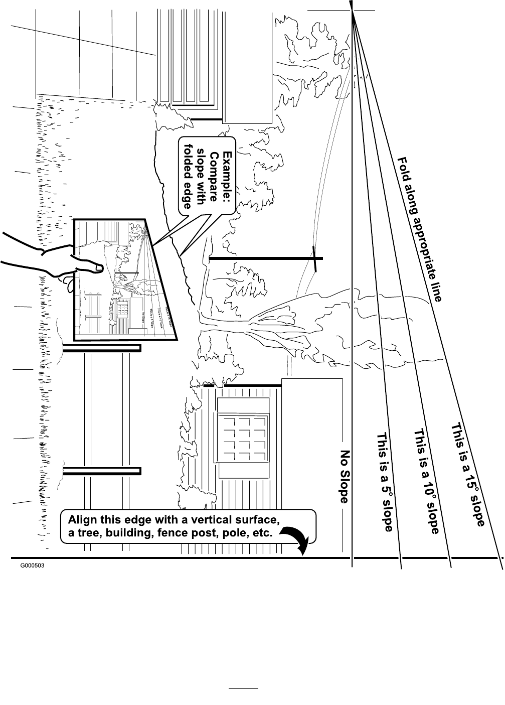
55

©
2007—2008 Exmark Mfg. Co., Inc. Part No. 4500-338 Rev.
A
Industrial Park Box 808 (402) 223-6300
Beatrice, NE 68310 Fax (402) 223-5489
All Rights Reserved Printed In USA.
