Extreme Networks 4018WP Wireless 802.11 abgn/ac Router User Manual WS AP3965 Wireless Access Points Quick Reference
Extreme Networks, Inc. Wireless 802.11 abgn/ac Router WS AP3965 Wireless Access Points Quick Reference
Users Manual
Installing the ExtremeWireless Indoor
AP3912i Access Point
Overview of the AP3912i
The AP3912i is a wall plate 11ac AP that lets you extend your
Wireless LAN. This model is ideal for installations that have
unused ports on existing Ethernet jacks because it has
minimal or no impact on the configuration of the
infrastructure switches (with only the requirement to
enable one extra port for the AP). Pass-through ports allow
wired devices, such as IP phones, to be connected. This wall
plate AP replaces existing Ethernet wall plates, eliminating
the need for mounting brackets. The AP3912i is designed
with four single-band internal antennas for indoor use only.
The AP enclosure is not plenum rated. (Operating
temperatures are 0ºC~40ºC.)
The AP3912i model has the following specifications:
• Radios: Two concurrent WiFi radios (2.4 GHz and 5 GHz)
and one radio that can operate as Bluetooth or ZigBee.
•LEDs: 6 (Figure 1)
• Power: 802.3at (PoE+) compliant for full functionality
• The AP3912i supports the 802.11ac and 802.11n wireless
standards, with full backward compatibility with legacy
802.11abg.
• The AP3912i interoperates fully with Wireless LAN,
including support for VoWLAN, branch office mode,
guest services, RTLS, availability and mobility.
• Enabled for use with an ExtremeCloudTM entitlement
For detailed installation information about the AP3912i, see
the ExtremeWireless AP3912i Installation Guide.
Power Requirements for the PSE Port
The AP3912i uses Power over Ethernet (PoE) as follows.
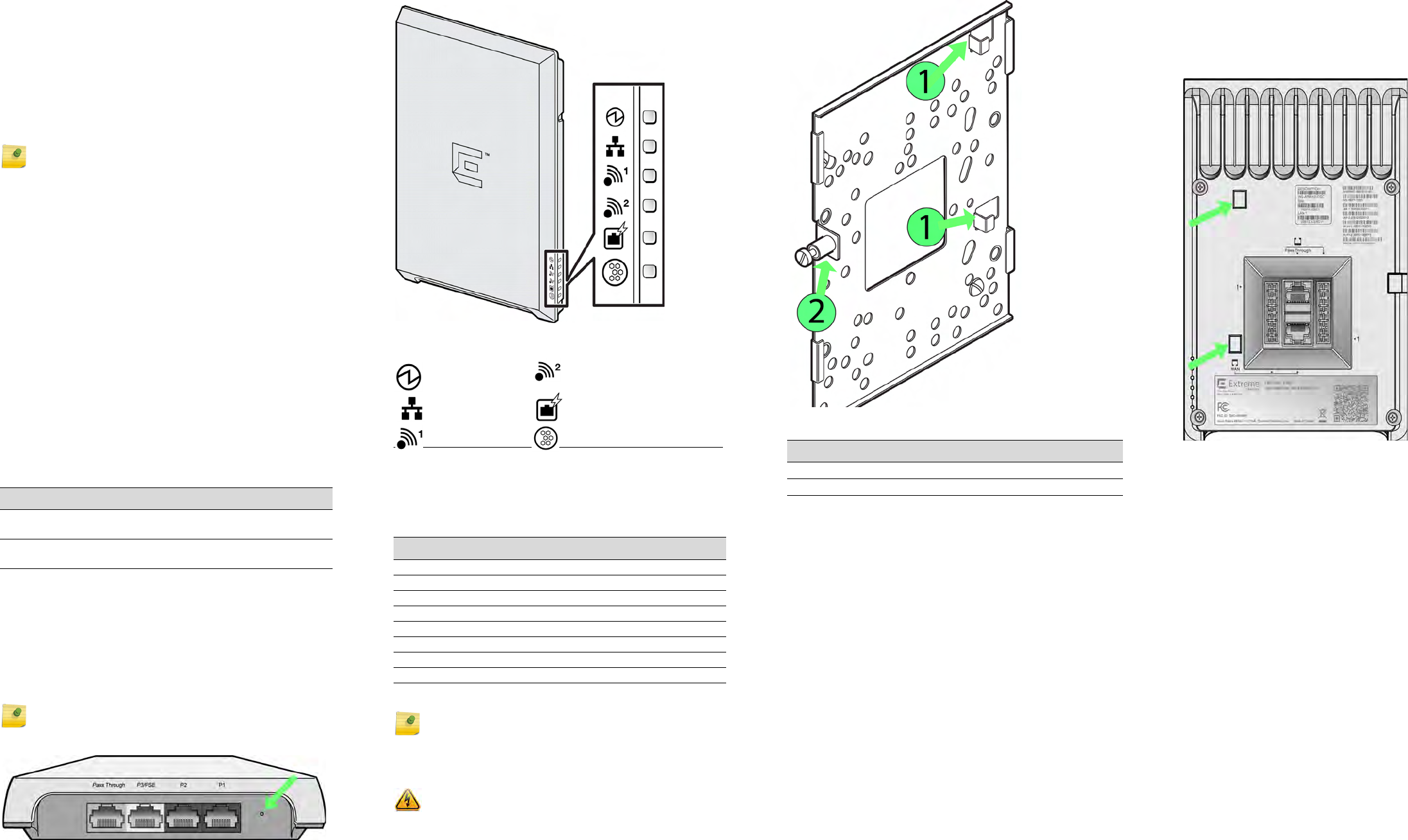
Power Connections and Reset Button
The AP3912i has three LAN ports (P1, P2, and P3/PSE), and
one pass-through port. On the pass-through port, power
and connection attributes (such as speed and duplex) of
devices are dictated by the characteristics of the
corresponding switch model and by the port that the
backend pass-through port is connected to.
Figure 1 Power Connections and Reset Button
Note: The AP3912i requires a minimum base firmware of
10.11.02.
Table 1 Power Sources
Power Source Description
PoE 802.3at Power is enabled on the Client PSE port
and the PSE LED is green.
PoE 802.3af Power is disabled on the Client PSE port
and the LED is off (not green).
Note: LAN connectors with shrouds will not fit into the
ports. Remove the shroud or use an optional jumper cable.
The Reset button (Figure 1) is to the right of the power
connections.
LEDs
LEDs are located on one side of the AP.
Figure 2 LEDs on Side of AP
Verifying the AP3912i Box Contents
Verify the contents of the box as listed in the following
table:
Mounting and Connecting the AP3912i
Use these instructions as guidelines for mounting and
connecting the AP3912i easily and safely. The installation of
the AP3912i should be performed by a professional installer
Status Radio 2 (2.4 GHz)
LAN 1 (Ethernet 1) PSE Client Port (PoE)
Radio 1 (5 GHz) BLE
Table 2 Contents of the AP3912i Box
Quantity Item
1AP3912i Quick Reference
1 ExtremeCloud Quick Start Card
1 WS-AP3912i AP
1 Wall plate bracket
The following hardware is included:
2 Screw-in wall anchors
2Pan-head machine screws
2Flat-head wood screws
Note: Before mounting the AP3912i, read the RF Safety
Distance section.
Electrical Hazard: Only qualified personnel should perform
installation procedures.
to ensure proper operation and compliance with local
safety guidelines.
Attach the AP3912i to an indoor wall or junction/gang box
only. The wall plate bracket is included with the AP box
contents.
Figure 3 Mounting Bracket
Mounting the AP3912i to a Wall
1 Using the mounting bracket (Figure 3) as a guide,
choose a location where it is feasible to place the AP’s
center. The bracket should have the captive screw on the
left, and the large, flat part of the bracket against the
wall. Decide which two holes to use to mount the bracket
to the wall.
2 Mark the two hole centers.
3 For drywall/plasterboard walls, drill two holes using a 1/
4” or 6mm diameter drill bit.
4 For drywall/plasterboard walls, screw the plastic anchors
into the holes.
5 Attach the wall plate bracket using the two wood screws.
Torque the screw to 12.0 in-lbs.
6 Connect the power and attach the AP to the mounting
bracket, as described below.
Mounting to a Junction/Gang Box
1 Place the bracket over the junction box with the captive
screw on the left side (Figure 3) and the large, flat plate
against the wall. The bracket should be attached to a
vertical surface.
Table 3
Number Description
1 AP Mounting Tab
2Captive Screw
2 Align two of the bracket holes with two of the box’s
holes. Use bracket holes that are closest to the center of
the bracket. Make sure that the entire box is covered by
the bracket.
3 Using the two pan head machine screws, attach the
bracket to the box using the aligned holes. Torque the
screws to 12.0 in-lbs.
4 Connect the power through the bracket to the AP, and
attach the AP to the mounting bracket, as described
below.
Figure 4 Back View
Connecting & Powering the AP3912i
Connect the building LAN1 wire (either PoE at or PoE af) to
the black RJ-45 connector, or associated punch-down
block, located on the rear of the AP.
• If PoE+ (802.3at) is connected, then the P3/PSE port will
offer PoE (802.3af) to connecting clients.
• If PoE (802.3af) is connected, then there will not be any
power on the P3/PSE port.
Mounting the AP to the Bracket
1 Line up the AP holes (see the arrows in Figure 4) on the
rear with the two "L" shaped angled tabs near the right
side of the bracket (Figure 3, item #1).
2 Slide the AP approximately 1/4” to the left on the two
bracket tabs.
3 Attach and tighten the captive screw (Figure 3) to the
AP so that the AP is attached to the bracket. Torque the
screw to 7.0 in-lbs.
ExtremeWirelessTM
Access Points
Quick Reference
P/N 31025 WS-AP3912i-FCC
P/N 31026 WS-AP3912i-ROW
Notice
Copyright © 2016 Extreme Networks, Inc. All Rights Reserved.
Legal Notices
Extreme Networks, Inc. reserves the right to make changes in specifications
and other information contained in this document and its website without
prior notice. The reader should in all cases consult representatives of
Extreme Networks to determine whether any such changes have been
made.
The hardware, firmware, software or any specifications described or referred
to in this document are subject to change without notice.
Trademarks
Extreme Networks and the Extreme Networks logo are trademarks or
registered trademarks of Extreme Networks, Inc. in the United States and/or
other countries.
All other names (including any product names) mentioned in this document
are the property of their respective owners and may be trademarks or
registered trademarks of their respective companies/owners.
For additional information on Extreme Networks trademarks, please see:
www.extremenetworks.com/company/legal/trademarks/
Documentation & Support
For product support, including documentation, visit:
www.extremenetworks.com/support/
Extreme Networks, Inc.
145 Rio Robles
San Jose, CA 19534
Tel: +1 408-579-2800
Toll-free: +1 888-257-3000
Regulatory and Compliance Information
Federal Communications Commission (FCC) Notice:
This equipment has been tested and found to comply with the limits for a
Class B digital device, pursuant to Part 15 of the FCC Rules. These limits are
designed to provide reasonable protection against harmful interference in a
residential installation. This equipment generates, uses and can radiate radio
frequency energy and, if not installed and used in accordance with the
instructions, may cause harmful interference to radio communications.
However, there is no guarantee that interference will not occur in a
particular installation. If this equipment does cause harmful interference to
radio or television reception, which can be determined by turning the
equipment off and on, the user is encouraged to try to correct the
interference by one of the following measures:
• Reorient or relocate the receiving antenna.
• Increase the separation between the equipment and receiver.
• Connect the equipment into an outlet on a circuit different from that to
which the receiver is connected.
• Consult the dealer or an experienced radio/TV technician for help.
.This device complies with Part 15 of the FCC Rules. Operation is subject to
the following two conditions: (1) This device may not cause harmful
interference, and (2) this device must accept any interference received,
including interference that may cause undesired operation.
This transmitter must not be co-located or operating in conjunction with any
other antenna or transmitter.
Operations in the 5.15-5.25GHz band are restricted to indoor usage only.
Industry Canada Notice:
This device complies with RSS-247 of the Industry Canada Rules. Operation
is subject to the following two conditions: (1) This device may not cause
harmful interference, and (2) this device must accept any interference
received, including interference that may cause undesired operation.
Ce dispositif est conforme à la norme CNR-247 d'Industrie Canada
applicable aux appareils radio exempts de licence. Son fonctionnement est
sujet aux deux conditions suivantes: (1) le dispositif ne doit pas produire de
brouillage préjudiciable, et (2) ce dispositif doit accepter tout brouillage
reçu, y compris un brouillage susceptible de provoquer un fonctionnement
indésirable.
Caution:
1 The device for operation in the band 5150-5250 MHz is only for indoor use
to reduce the potential for harmful interference to co-channel mobile
satellite systems;
2 High-power radars are allocated as primary users (i.e. priority users) of the
bands 5250-5350 MHz and 5650-5850 MHz and that these radars could
cause interference and/or damage to LE-LAN devices.
Warning: Any changes or modifications not expressly approved by
the party responsible for compliance could void the user's authority
to operate this equipment
Warning: FCC Radiation Exposure Statement: This
equipment complies with FCC radiation exposure limits set forth for
an uncontrolled environment. This equipment should be installed
and operated with minimum distance 20cm between the radiator &
your body.
Avertissement:
1 Les dispositifs fonctionnant dans la bande 5150-5250 MHz sont réservés
uniquement pour une utilisation à l’intérieur afin de réduire les risques de
brouillage préjudiciable aux systèmes de satellites mobiles utilisant les
mêmes canaux;
2 De plus, les utilisateurs devraient aussi être avisés que les utilisateurs de
radars de haute puissance sont désignés utilisateurs principaux (c.-à-d.,
qu’ils ont la priorité) pour les bandes 5250-5350 MHz et 5650-5850 MHz
et que ces radars pourraient causer du brouillage et/ou des dommages
aux dispositifs LAN-EL.
For Mobile Device Usage
Safety Guidelines
This section contains notices that you must adhere to ensure your personal
safety and to prevent any damage to the equipment.
Qualified Personnel:
European Waste Electrical and Electronic
Equipment (WEEE) Notice
In accordance with Directive 2012/19/EU of the European Parliament on
waste electrical and electronic equipment (WEEE):
1 The symbol above indicates that separate collection of electrical and
electronic equipment is required.
2 When this product has reached the end of its serviceable life, it cannot be
disposed of as unsorted municipal waste. It must be collected and treated
separately.
3 It has been determined by the European Parliament that there are
potential negative effects on the environment and human health as a
result of the presence of hazardous substances in electrical and electronic
equipment.
4 It is the users’ responsibility to utilize the available collection system to
ensure WEEE is properly treated.
For information about the available collection system, please contact
Extreme Customer Support at 353 61 705500 (Ireland).
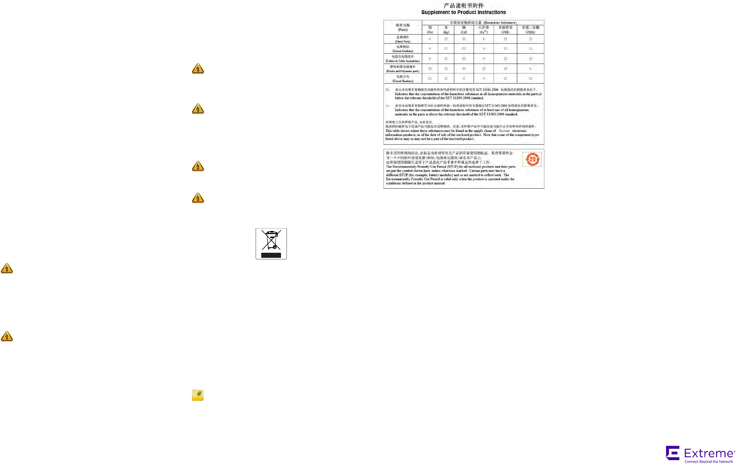
Hazardous Substances
This product complies with the requirements of Directive 2011/65/EU of the
European Parliament and of the Council of 8 June 2011 on the restriction of
the use of certain hazardous substances in electrical and electronic
equipment.
Declaration of Conformity in Languages of the European Community
Hereby, Extreme Networks, Inc. declares that the radio equipment type
Wireless LAN Access Point is in compliance with Directive 1999/5/EC. The
full text of the EU declaration of conformity is available at the following
Internet address:
http://www.extremenetworks.com/
Warning: Radiation Exposure Statement: This equipment
complies with IC radiation exposure limits set forth for an
uncontrolled environment. This equipment should be installed and
operated with minimum distance 20cm between the radiator & your
body.
Warning: Déclaration d'exposition aux radiations: Cet
équipement est conforme aux limites d'exposition aux
rayonnements IC établies pour un environnement non contrôlé. Cet
équipement doit être installé et utilisé avec un minimum de 20cm de
distance entre la source de rayonnement et votre corps.
Caution: The unit and all interconnected equipment must be
installed indoors within the same building, including all PoE-
powered network connections as described by Environment A of
the IEEE 802.3af standard.
Electrical Hazard: Only qualified personnel should perform
installation procedures.
Note: Changes or modifications made to this device which are not
expressly approved by the party responsible for compliance could
void the user’s authority to operate the equipment.
NCC Statement
低功率電波輻射性電機管理辦法
第十二條 經型式認證合格之低功率射頻電機,非經許
可,公司、商號或使用者均不得擅自變更頻
率、加大功率或變更原設計之特性及功能。
第十四條 低功率射頻電機之使用不得影響飛航安全及
干擾合法通信;經發現有干擾現象時,應立
即停用,並改善至無干擾時方得繼續使用。
前項合法通信,指依電信法規定作業之無線
電通信。
低功率射頻電機須忍受合法通信或工業、科
學及醫療用電波輻射性電機設備之干擾。
在5.25-5.35 秭赫頻帶內操作之無線資訊傳輸設備,限
於室內使用。
電磁波曝露量 MPE 標準值 1mW/cm2,本產品使用時
建議應距離人體 20cm
P/N 9035015-01 Rev-00