Extreme Networks 4019IC Wireless 802.11a/AC+b/g/n Acess Point with integral Camera User Manual WS AP3965 Wireless Access Points Quick Reference
Extreme Networks, Inc. Wireless 802.11a/AC+b/g/n Acess Point with integral Camera WS AP3965 Wireless Access Points Quick Reference
User Manual
Installing the ExtremeWireless Indoor
AP3916ic Access Point
Overview of the AP3916ic
The AP3916ic is an 11ac Wave 2 AP with an integral security
camera that lets you extend your Wireless LAN and provide
simultaneous Wi-Fi service, BLE or 802.15.4 coverage and
security in public spaces, such as classrooms and offices.
This fully featured access point can be mounted on the
ceiling or wall. The integral ONVIF compatible security
camera is connected to an internal wired Ethernet port. The
AP3916ic provides flow based data handling for the
wireless and wired connections.
The AP3916ic model has the following specifications:
• Integrated 2MP camera with resolution up to 1080p, with
manual view adjustment.
• Radios: Two concurrent Wi-Fi radios (2.4 GHz and 5
GHz) and one additional radio that can operate as
Bluetooth or 802.15.4.
• Antennas: Four internal single band Wi-Fi antennas and
one internal antenna for Bluetooth (BLE) or 802.15.4.
•LEDs: 6 (see Figure 2)
• 802.3at (PoE+) compliant for full functionality. Optional
AC adapter.
• Supports the 802.11ac and 802.11n wireless standards,
with full backward compatibility with legacy 802.11abg.
• 10/100/1000 Mbps operation.
• Adjustable mounting bracket (included) for drop-ceiling
T-bar rail.
• Optional mounts can be purchased separately for
junction/gang box, indoor wall and solid ceiling
installation.
• Enabled for ExtremeCloud support.
For complete installation information, see the
ExtremeWireless AP3916ic Installation Guide
Software Dependencies
The camera functionality is represented as an attached
client to the AP. The IP address from the camera can be
retrieved from the Client report in the ExtremeWireless user
interface.
A Port/User specific policy can be assigned to the camera
function, such as mapping all camera interactions like video
streaming or management to its own network segment or
VLAN.
The ONVIF compliant camera is discoverable using
standard ONVIF/IP camera methods. ONVIF utilizes
multicast as the means of advertising and inquiring about
device presence. Therefore, the default topology of the role
associated to the camera port must be adjusted to allow for
multicast. We recommend configuring the All Multicast
(0.0.0.0/0) setting for Groups in the ExtremeWireless
topology.
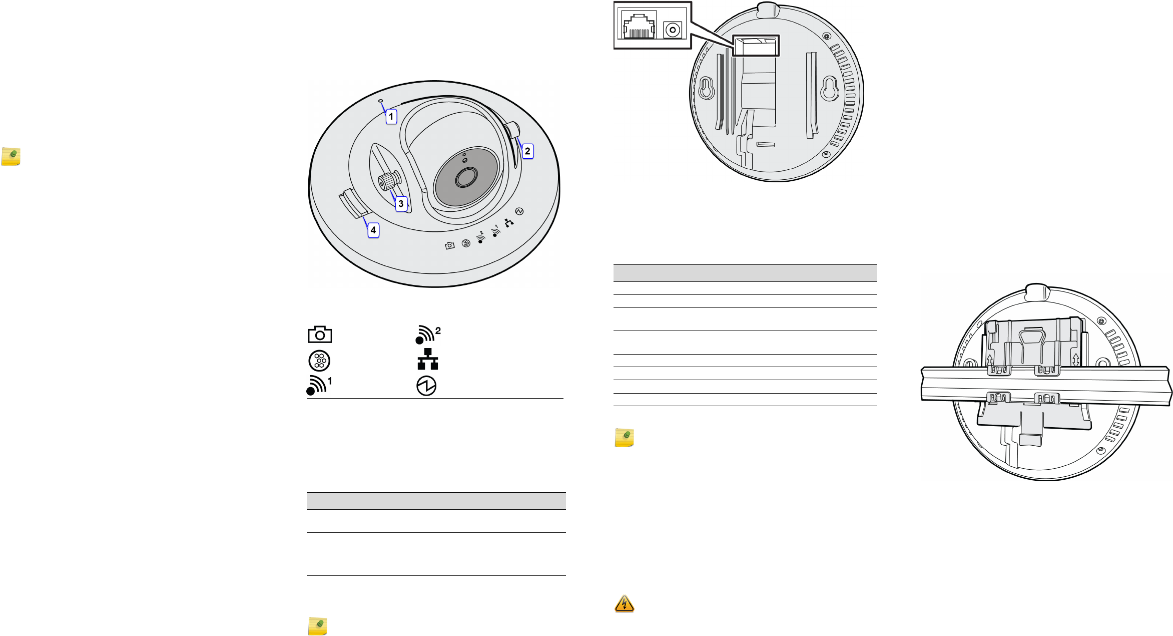
Front View Features
1 The power reset button is recessed and located on the
top of the AP. Use a tool to press the reset button. See
Figure 1.
2 Remove the caps to access the thumbscrews. See
Figure 1.
Note: The AP3916ic requires a minimum base firmware of
10.31.01.
3 The thumbscrews let you adjust and set the tilt angle of
the camera. See Figure 1.
4 The locking pin lets you adjust and set the rotational
position of the camera. See Figure 1.
Figure 1 Front View
LEDs are located on the top cover of the AP.
Uplink and Power Connections
The AP uses Power over Ethernet (PoE) or an external
power supply:
The AP has a LAN 1 port that is powered using 802.3at.
Camera Radio 2 (2.4 GHz)
IoT (BLE or
802.15.4)
LAN 1 (Ethernet 1)
Radio 1 (5 GHz) Status
Table 1 Power Sources
Power Source Description
LAN 1 - uplink PoE
port
LAN 1 may be connected using an
802.3at or 802.3af switch port
External 12V DC power
supply (optional)
This AP can also be powered by an
external DC power supply plugged into
an AC source. Plug the supply’s input
jack into the DC-In port (see Figure 2).
Note: LAN connectors with shrouds will not fit into the
ports. Remove the shroud or use an optional jumper cable.
Figure 2 Power Connections and Rear View
Verifying the AP3916ic Box Contents
Verify the contents of the box as follows:
Mounting and Connecting the AP3916ic
Use these instructions as guidelines for mounting and
connecting the AP3916ic easily and safely.
The AP3916ic comes with a bracket for mounting on a
drop-ceiling.
An optional bracket P/N 30516 (WS-MBI-WALL04 wall
mounting bracket) is sold separately. This bracket is used
for mounting the AP on a solid ceiling, indoor wall, or
junction/gang box. For more information about installing
the optional bracket, see the ExtremeWireless AP3916ic
Installation Guide.
Mounting to a Drop Ceiling
1 Remove the ceiling panels around the drop ceiling T-bar
rail and verify that the Ethernet cable can reach the AP at
the mounting point.
2 To connect the LAN/Ethernet cable, make a hole through
the ceiling panel closest to the power slot on the AP. Run
the cable through the hole and into the LAN 1 port in the
recessed connector bay. See Figure 2.
Table 2 Contents of the AP3916ic Box
Quantity Item
1 AP3916ic Quick Reference
1 ExtremeCloud Quick Start Card
1 WS-AP3916ic AP (includes two M3 security torx
captive screws
1 Adjustable mounting bracket for drop ceiling T-bar
rail.
The following hardware is included:
2 Screw-in plastic wall anchors
2 Pan-head screws for wall mounting
1 Security torx screwdriver/bit
Note: Before mounting the AP3916ic, read the Safety
Guidelines section.
Note: A Kensington lock (or equivalent) is recommended
to secure the AP. Also, the security torx screw is used to
prevent movement of the camera angle.
3 If your LAN does not have PoE, you must also connect to
an AC power source by plugging the external 12V DC
adapter power cord into the power connector on the
back of the AP. See Figure 2. (There is no wall mount for
the 12V DC power supply.) Then plug the other end of
power cord into the AC electrical outlet.
4 Slide the T-bar ceiling mount bracket base into the
access point’s metal base. The locking tab fits into the
groove in the outside center of the back of the AP. See
Figure 3.
5 Slightly lift the movable T-bar locking tab to increase the
space between the stationary and the slider T-bar sides
of the bracket. Then hook the stationary end of the T-bar
bracket onto the T-bar, as shown in Figure 3.
6 While holding the AP with one hand, reach the other
hand over the T-bar and grasp both the stationary and
movable sides of the bracket. Push the bracket parts
together so they both grasp the T-bar and the locking
tab clicks into place.
7 While still holding the AP, rock it back and forth to ensure
that it is securely mounted.
8 (Optional) Attach the Kensington lock and cable (or
equivalent) to secure the AP to the bracket.
Figure 3 Mounting Bracket on T-bar
Adjusting the Camera
1 To adjust the rotational camera movement, pull and hold
the rotating locking pin outwards while rotating the
camera. Release the locking pin when the camera is
positioned. See Figure 1.
2 To adjust the tilt movement, remove the thumbscrew
caps and loosening the thumbscrews. Then, without
touching the camera face, move the camera to the
desired tilt angle. Tighten the thumbscrews and put the
caps back on. Torque the screws to 7.0 in-lbs. See
Figure 1.
3 Remove the plastic protective cover from the face of the
camera.
ExtremeWirelessTM
Access Points
Quick Reference
P/N 31034 WS-AP3916ic-FCC
P/N 31035 WS-AP3916ic-ROW
Notice
Copyright © 2017 Extreme Networks, Inc. All Rights Reserved.
Legal Notices
Extreme Networks, Inc. reserves the right to make changes in specifications
and other information contained in this document and its website without
prior notice. The reader should in all cases consult representatives of
Extreme Networks to determine whether any such changes have been
made.
The hardware, firmware, software or any specifications described or referred
to in this document are subject to change without notice.
Trademarks
Extreme Networks and the Extreme Networks logo are trademarks or
registered trademarks of Extreme Networks, Inc. in the United States and/or
other countries.
All other names (including any product names) mentioned in this document
are the property of their respective owners and may be trademarks or
registered trademarks of their respective companies/owners.
For additional information on Extreme Networks trademarks, please see:
www.extremenetworks.com/company/legal/trademarks/
Documentation & Support
For product support, including documentation, visit:
www.extremenetworks.com/support/
Extreme Networks, Inc.
6480 Vía Del Oro
San Jose, CA 95119
Tel: +1 408-579-2800
Toll-free: +1 888-257-3000
Regulatory and Compliance Information
Federal Communications Commission (FCC) Notice:
This equipment has been tested and found to comply with the limits for a
Class B digital device, pursuant to Part 15 of the FCC Rules. These limits are
designed to provide reasonable protection against harmful interference in a
residential installation. This equipment generates, uses and can radiate radio
frequency energy and, if not installed and used in accordance with the
instructions, may cause harmful interference to radio communications.
However, there is no guarantee that interference will not occur in a
particular installation. If this equipment does cause harmful interference to
radio or television reception, which can be determined by turning the
equipment off and on, the user is encouraged to try to correct the
interference by one of the following measures:
• Reorient or relocate the receiving antenna.
• Increase the separation between the equipment and receiver.
• Connect the equipment into an outlet on a circuit different from that to
which the receiver is connected.
• Consult the dealer or an experienced radio/TV technician for help.
.This device complies with Part 15 of the FCC Rules. Operation is subject to
the following two conditions: (1) This device may not cause harmful
interference, and (2) this device must accept any interference received,
including interference that may cause undesired operation.
This transmitter must not be co-located or operating in conjunction with any
other antenna or transmitter. For indoor use only.
Industry Canada Notice:
This device complies with RSS-247 of the Industry Canada Rules. Operation
is subject to the following two conditions: (1) This device may not cause
harmful interference, and (2) this device must accept any interference
received, including interference that may cause undesired operation.
Ce dispositif est conforme à la norme CNR-247 d'Industrie Canada
applicable aux appareils radio exempts de licence. Son fonctionnement est
sujet aux deux conditions suivantes: (1) le dispositif ne doit pas produire de
brouillage préjudiciable, et (2) ce dispositif doit accepter tout brouillage
reçu, y compris un brouillage susceptible de provoquer un fonctionnement
indésirable.
Caution:
1 The device for operation in the band 5150-5250 MHz is only for indoor use
to reduce the potential for harmful interference to co-channel mobile
satellite systems;
2 High-power radars are allocated as primary users (i.e. priority users) of the
bands 5250-5350 MHz and 5650-5850 MHz and that these radars could
cause interference and/or damage to LE-LAN devices.
Warning: Any changes or modifications not expressly approved by
the party responsible for compliance could void the user's authority
to operate this equipment
Warning: FCC Radiation Exposure Statement: This
equipment complies with FCC radiation exposure limits set forth for
an uncontrolled environment. This equipment should be installed
and operated with minimum distance 21cm between the radiator &
your body.
Avertissement:
1 Les dispositifs fonctionnant dans la bande 5150-5250 MHz sont réservés
uniquement pour une utilisation à l’intérieur afin de réduire les risques de
brouillage préjudiciable aux systèmes de satellites mobiles utilisant les
mêmes canaux;
2 De plus, les utilisateurs devraient aussi être avisés que les utilisateurs de
radars de haute puissance sont désignés utilisateurs principaux (c.-à-d.,
qu’ils ont la priorité) pour les bandes 5250-5350 MHz et 5650-5850 MHz
et que ces radars pourraient causer du brouillage et/ou des dommages
aux dispositifs LAN-EL.
For Mobile Device Usage
Safety Guidelines
This section contains notices that you must adhere to ensure your personal
safety and to prevent any damage to the equipment.
European Waste Electrical and Electronic
Equipment (WEEE) Notice
In accordance with Directive 2012/19/EU of the European Parliament on
waste electrical and electronic equipment (WEEE):
1 The symbol above indicates that separate collection of electrical and
electronic equipment is required.
2 When this product has reached the end of its serviceable life, it cannot be
disposed of as unsorted municipal waste. It must be collected and treated
separately.
3 It has been determined by the European Parliament that there are
potential negative effects on the environment and human health as a
result of the presence of hazardous substances in electrical and electronic
equipment.
4 It is the users’ responsibility to utilize the available collection system to
ensure WEEE is properly treated.
For information about the available collection system, please contact
Extreme Customer Support at 353 61 705500 (Ireland).
Hazardous Substances
This product complies with the requirements of Directive 2011/65/EU of the
European Parliament and of the Council of 8 June 2011 on the restriction of
the use of certain hazardous substances in electrical and electronic
equipment.
Declaration of Conformity in Languages of the European Community
Hereby, Extreme Networks, Inc. declares that the radio equipment type
Wireless LAN Access Point is in compliance with Directive 1999/5/EC. The
full text of the EU declaration of conformity is available at the following
Internet address:
http://www.extremenetworks.com/
Warning: Radiation Exposure Statement: This equipment
complies with IC radiation exposure limits set forth for an
uncontrolled environment. This equipment should be installed and
operated with minimum distance 21cm between the radiator & your
body.
Attention! Déclaration d'exposition aux radiations: Cet
équipement est conforme aux limites d'exposition aux
rayonnements IC établies pour un environnement non contrôlé. Cet
équipement doit être installé et utilisé avec un minimum de 21cm de
distance entre la source de rayonnement et votre corps.
Caution: The unit and all interconnected equipment must be
installed indoors within the same building, including all PoE-
powered network connections as described by Environment A of
the IEEE 802.3af standard.
Note: Changes or modifications made to this device which are not
expressly approved by the party responsible for compliance could
void the user’s authority to operate the equipment.
NCC Statement
低功率電波輻射性電機管理辦法
第十二條 經型式認證合格之低功率射頻電機,非經許
可,公司、商號或使用者均不得擅自變更頻
率、加大功率或變更原設計之特性及功能。
第十四條 低功率射頻電機之使用不得影響飛航安全及
干擾合法通信;經發現有干擾現象時,應立
即停用,並改善至無干擾時方得繼續使用。
前項合法通信,指依電信法規定作業之無線
電通信。
低功率射頻電機須忍受合法通信或工業、科
學及醫療用電波輻射性電機設備之干擾。
在5.25-5.35 秭赫頻帶內操作之無線資訊傳輸設備,限
於室內使用。
電磁波曝露量 MPE 標準值 1mW/cm2,送測產品實測值
為0.315mW/cm2
P/N 9035053-02