Extreme Networks 4411AC Wireless 802.11a/AC+ b/g/n Access Point User Manual
Extreme Networks, Inc. Wireless 802.11a/AC+ b/g/n Access Point Users Manual
Users Manual
Overview of the AP3935
The AP3935 is designed to extend your Wireless LAN
around indoor locations. The AP3935 supports the 802.11ac
and 802.11n wireless standards, with full backward
compatibility with legacy 802.11a, and 802.11b/g devices.
The AP3935 interoperates fully with Wireless LANs,
including support for VoWLAN, branch office mode, guest
services, RTLS, availability, and mobility features.
Operating Temp: 0 - 50C.
AP3935 models have the following features:
• Radios: 2 radios (2.4 GHz and 5 GHz)
•LEDs: 5 (see Figure 3)
• Power: PoE 802.3at for full performance; (802.3af for low
performance mode) DC power supply (see Table 1).
• Antennas:
– WS-AP3935i: 8 internal single band antenna
assemblies
– WS-AP3935e: 8 external RPSMA antenna connectors
(external antennas must be ordered separately)
• Adjustable mounting brackets for drop ceiling T-bar rail.
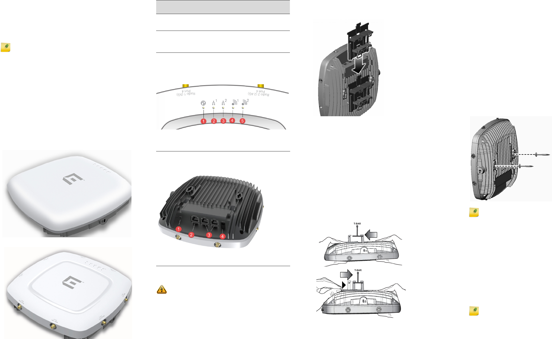
Figure 1 3935i Access Point
Figure 2 3935e Access Point
For detailed installation information about the AP3935, see
the ExtremeWireless AP3935 Installation Guide.
Note: The AP3935 is available in both an “i” model (with
internal antennas) and an “e” model (with external
antennas). In this Quick Reference, any reference to
AP3935applies to both models.
Ta b l e 1 shows ways to power the AP3935.
Figure 3 shows the LEDs on the front of the AP3935e.
Figure 3 LEDs on AP Front Face
Figure 4 3935e Access Point bottom view
Mounting and Connecting the AP
Mounting brackets are included for quick and easy
mounting of the AP3935 drop ceilings. The wall bracket as
shown in Figure 7 is optional.
Use these instructions as guidelines for mounting and
connecting the AP3935 easily and safely.
Mount the AP no more than 2 ft. from a T-bar support.
Table 1 Powering the AP3935
Power
Source Description
Power over
Ethernet
(PoE)
Power is provided through two Ethernet ports (LAN
port). This is the preferred method of powering the
AP on ceiling and wall installations.
External 12V
DC power
supply
(optional)
The AP3935 can also be powered by an external DC
power supply plugged into an AC source. Plug the
supply’s input jack into the DC-In port (Callout 4 in
Figure 4).
1Status 4Radio 1 (5 GHz)
2LAN 1 (Ethernet 1) 5Radio 2 (2.4 GHz)
3LAN 2 (Ethernet 2)
1Reset Button 3LAN Ethernet Ports 1 and 2
2Console Port 4External Power DC 12V
Electrical Hazard: Only qualified personnel should perform
installation procedures.
Mounting on a Drop Ceiling
1 Slide the ceiling mount bracket base into the metal base.
The locking tab fits into the groove in the fins. See
Figure 5.
Figure 5 Attaching Mount Bracket to the Access Point
2 Remove the ceiling panels around the drop ceiling T-bar
rails and verify that the Ethernet cable can reach the AP
at the mounting point.
3 Slightly lift the movable T-bar locking tab to increase the
space between the stationary and the slider T-bar sides
of the bracket. Then hook the stationary end of the T-bar
bracket onto the T-bar, as shown in Figure 6.
4 While holding the AP with one hand, reach the other
hand over the T-bar and grasp both the stationary and
movable sides of the bracket. Push the bracket parts
together so they both grasp the T-bar and the locking
tab clicks into place.
5 While still holding the AP, rock it back and forth to ensure
that it is securely mounted.
Figure 6 Attaching the AP3935 on a drop ceiling T-bar
rail
6 Make a hole through the ceiling panel closest to the
power slot on the AP. Run the Ethernet cable through the
hole and into an RJ45 LAN port in the recessed
connector bay.
7 If necessary, cut the tiles for the cables, attach the cables
to the AP, and replace the tiles. Then replace the
displaced ceiling panels.
Mounting on a Wall/Solid Flat Ceiling
1 Determine the spot on the wall to mount the AP (near
the ceiling, but in reach of the Ethernet cable and a wall
power outlet if you are using external power).
2 To mount the AP directly on the wall with two screws,
use the provided template and mark the two drill holes
on the wall. In drywall, the drill holes should be 6MM to
0.250" in diameter.
3 Drill two holes in the wall to match the center of the two
keyhole slots in the back of the AP bracket.
4 Screw the anchors into the holes until they are flush with
the wall, Screw the provided mounting screws into the
anchors with the head protruding 1/16” from the anchor.
5 Place the back of the AP against the wall with the
protruding mounting screw heads fitting through the
keyhole slots on the back of the AP. Slide the AP down
until the AP rests on the mounting screw heads.
6 For added stability and security, use a Kensington lock.
When mounting on the ceiling, a Kensington lock and
bracket are required.
Figure 7 Mounting the AP3935 to a Flat Wall.
Connecting a Power Supply to the AP3935
To power the AP3935 with optional (30512, WS-PSI12-MR2)
external 12V DC power supply, plug the power cord into the
power connector (Figure 4) on the back of the AP. There is
no wall mount for the 12V DC power supply. When the
device is powered on, the power LED on the front face of
the AP is lit.
LAN/Console Connections
The AP3935 has two LAN (Ethernet) ports and a Console
port. Refer to Figure 4 for the location of these ports.
During administration and maintenance, the AP must have
a power connection through either an Ethernet PoE cable
or a DC power supply.
External Antennas (WS-AP3935e Only)
Install the external antennas intended for area coverage.
For more information about the optional installation
bracket, the optional power supply, and antenna selection
and installation, refer to the ExtremeWireless AP3935
Installation Guide.
Note: You can mount the AP using an optional mounting
bracket (30513, WS-MBI-WALL03) to a flat ceiling.
Note: LAN/Console connectors with shrouds will not fit into
the ports. Remove the shroud or use an optional jumper
cable.
ExtremeWirelessTM
Access Points
Quick Reference
P/N 31012 WS-AP3935i-FCC
P/N 31013 WS-AP3935i-ROW
P/N 31014 WS-AP3935e-FCC
P/N 31015 WS-AP3935e-ROW
Notice
Copyright © 2015 Extreme Networks, Inc. All Rights Reserved.
Legal Notices
Extreme Networks, Inc. reserves the right to make changes in specifications
and other information contained in this document and its website without
prior notice. The reader should in all cases consult representatives of
Extreme Networks to determine whether any such changes have been
made.
The hardware, firmware, software or any specifications described or referred
to in this document are subject to change without notice.
Trademarks
Extreme Networks and the Extreme Networks logo are trademarks or
registered trademarks of Extreme Networks, Inc. in the United States and/or
other countries.
All other names (including any product names) mentioned in this document
are the property of their respective owners and may be trademarks or
registered trademarks of their respective companies/owners.
For additional information on Extreme Networks trademarks, please see:
www.extremenetworks.com/company/legal/trademarks/
Documentation & Support
For product support, including documentation, visit:
www.extremenetworks.com/support/
Contact
Extreme Networks, Inc.
145 Rio Robles
San Jose, CA 95134 USA
Tel: +1 408-579-2800
Toll-free: +1 888-257-3000
Regulatory and Compliance Information
Safety Guidelines
This section contains notices that are intended to protect your personal
safety and prevent damage to the equipment.
Suitable for use in environmental air space in accordance with Section
300.22.C of the National Electrical Code, and Sections 2-128, 12-010(3) and
12-100 of the Canadian Electrical Code, Part 1,C22.1.
Convient à l'espace de ventilation environnemental, conformément à la
section 300.22.C du Code national de l'électricité et aux sections 2-128, 12-
010(3) et 12-100 du Code canadien de l'électricité, partie 1, C22.1.
Qualified Personnel:
Federal Communications Commission (FCC) Notice
This device complies with Part 15 of the FCC rules. Operation is subject to
the following two conditions: (1) this device may not cause harmful
interference, and (2) this device must accept any interference received,
including interference that may cause undesired operation.
The antennas used for this transmitter must be installed to provide a
separation distance of at least 25 cm from all persons and must not be co-
located or operating in conjunction with another antenna or transmitter.
Industry Canada Notice
This device complies with Industry Canada license-exempt RSS standard(s).
Operation is subject to the following two conditions: (1) this device may not
cause interference, and (2) this device must accept any interference,
including interference that may cause undesired operation of the device.
Le présent appareil est conforme aux CNR d'Industrie Canada applicables
aux appareils radio exempts de licence. L'exploitation est autorisée aux deux
conditions suivantes : (1) l'appareil ne doit pas produire de brouillage, et (2)
l'utilisateur de l'appareil doit accepter tout brouillage radioélectrique subi,
même si le brouillage est susceptible d'en compromettre le fonctionnement.
This radio transmitter (IC: 4141B-4411AC) has been approved by Industry
Canada to operate with the antenna types listed below with the maximum
Electrical Hazard: Only qualified personnel should perform
installation procedures. Within the context of the safety
notes in this documentation, qualified persons are defined
as persons who are authorized to commission, ground and
label devices, systems, and circuits in accordance with
established safety practices and standards. A qualified
person understands the requirements and risks involved
with installing outdoor electrical equipment in accordance
with national codes.
Caution: Connect the equipment to Intra-Building networks
only. Do not route cables outside.
Attention: Connecter l'équipement à des réseaux intra-
bâtiment seulement . Ne pas acheminer les câbles à
l'extérieur.
Note: Changes or modifications made to this device which
are not expressly approved by the party responsible for
compliance could void the user’s authority to operate the
equipment.
permissible gain and required antenna impedance for each antenna type
indicated. Antenna types not included in this list, having a gain greater than
the maximum gain indicated for that type, are strictly prohibited for use with
this device.
Le présent émetteur radio (IC: 4141B-4411AC) a été approuvé par Industrie
Canada pour fonctionner avec les types d'antenne énumérés ci-dessous et
ayant un gain admissible maximal et l'impédance requise pour chaque type
d'antenne. Les types d'antenne non inclus dans cette liste, ou dont le gain
est supérieur au gain maximal indiqué, sont strictement interdits pour
l'exploitation de l'émetteur.
Antenna List:
Note: All antennas use an RP SMA Male connector.
The antennas used for this transmitter must be installed to provide a
separation distance of at least 34 cm from all persons and must not be co-
located or operating in conjunction with another antenna or transmitter.
Cet équipement est conforme aux limites d'exposition aux rayonnements IC
établies pour un environnement non contrôlé. Cet équipement doit être
installé et utilisé avec un minimum de 34 cm de distance entre la source de
rayonnement et votre corps.
Dynamic Frequency Selection (DFS) for devices operating in the bands
5250- 5350 MHz,
5470-5600 MHz and 5650-5725 MHz
Sélection dynamique de fréquences (DFS) pour les dispositifs fonctionnant
dans les bandes 5250-5350 MHz, 5470-5600 MHz et 5650-5725 MHz
The device for operation in the band 5150-5250 MHz is only for indoor use to
reduce the potential for harmful interference to co-channel mobile satellite
systems.
les dispositifs fonctionnant dans la bande 5150-5250 MHz sont réservés
uniquement pour une utilisation à l'intérieur afin de réduire les risques de
brouillage préjudiciable aux systèmes de satellites mobiles utilisant les
mêmes canaux.
The maximum antenna gain permitted for devices in the bands 5250-5350
MHz and 5470-5725 MHz shall be such that the equipment still complies
with the e.i.r.p. limit.
le gain maximal d'antenne permis pour les dispositifs utilisant les bandes
5250-5350 MHz et
5470-5725 MHz doit se conformer à la limite de p.i.r.e.
The maximum antenna gain permitted for devices in the band 5725-5850
MHz shall be such that the equipment still complies with the e.i.r.p. limits
specified for point-to-point and non-point-to-point operation as
appropriate.
le gain maximal d'antenne permis (pour les dispositifs utilisant la bande
5725-5850 MHz)
doit se conformer à la limite de p.i.r.e. spécifiée pour l'exploitation point à
point et non point à point, selon le cas.
For product available in the USA/Canada market, only channel 1~11 can be
operated. Selection of other channels is not possible.
Pour les produits disponibles aux États-Unis / Canada du marché, seul le
canal 1 à 11 peuvent être exploités. Sélection d'autres canaux n'est pas
possible.
High-power radars are allocated as primary users (i.e. priority users) of the
bands 5250-5350 MHz and 5650-5850 MHz and that these radars could
cause interference and/or damage to LE-LAN devices.
Les radars à haute puissance sont désignés comme utilisateurs principaux
(c. utilisateurs prioritaires ) des bandes 5250-5350 MHz et 5650-5850 MHz
et que ces radars pourraient provoquer des interférences et / ou
endommager les appareils LE- LAN.
Hazardous Substances
This product complies with the requirements of Directive 2011/65/EU of the
European Parliament and of the Council of 8 June 2011 on the restriction of
the use of certain hazardous substances in electrical and electronic
equipment.
Part No.
(Short Description)
Frequency
Band
Antenna
Type
2.4G
Gain
5G
Gain
30702 (WS-AI-DQ05120) 2.4G/5G Sector 5.5 5.5
30703 (WS-AI-5Q04060) 5G Sector N/A 4
30704 (WS-AI-2Q05060) 2.4G Sector 5 N/A
30705 (WS-AI-DE07025) 2.4G/5G Sector 7.5 6.5
30706 (WS-AI-5Q05025) 5G Sector N/A 4.5
30707 (WS-AI-DE10055) 2.4G/5G Sector 10.5 7.5
30709 (WS-ANT-2DIP-4) 2.4G DIPOLE 4.66 N/A
30710 (WS-ANT-5DIP-4) 5G DIPOLE N/A 4.67
WS-AI-DQ04360
(WS-AI-DQ04360)
2.4G/5G Ceiling
Mount
Omni
47
European Waste Electrical and Electronic
Equipment (WEEE) Notice
In accordance with Directive 2012/19/EU of the European Parliament on
waste electrical and electronic equipment (WEEE):
1 The symbol above indicates that separate collection of electrical and
electronic equipment is required.
2 When this product has reached the end of its serviceable life, it cannot be
disposed of as unsorted municipal waste. It must be collected and treated
separately.
3 It has been determined by the European Parliament that there are
potential negative effects on the environment and human health as a
result of the presence of hazardous substances in electrical and electronic
equipment.
4 It is the users’ responsibility to utilize the available collection system to
ensure WEEE is properly treated.
For information about the available collection system, please contact
Extreme Customer Support at +353 61 705500 (Ireland).
NCC Statement
(1) 「經型式認證合格之低功率射頻電機,非經許可,公司、商號或使用者均不得擅
自變更頻率、加大功率或變更原設計之特性及功能」。
(2) 「低功率射頻電機之使用不得影響飛航安全及干擾合法通信;經發現有干擾現象
時,應立即停用,並改善至無干擾時方得繼續使用。前項合法通信,指依電
信法規定作業之無線電通信。低功率射頻電機須忍受合法通信或工業、科學
及醫療用電波輻射性電機設備之干擾」。
(3) 「電磁波曝露量 MPE 標準值 1mW/cm2,本產品使用時建議應距離人體:25
cm」。
(4) 「本器材須經專業工程人員安裝及設定,始得設置使用,且不得直接販售給一般
消費者
Declaration of Conformity in Languages of the
European Community
Hereby, Extreme Networks, Inc. declares that the radio equipment type
Wireless LAN Access Point is in compliance with Directive 1999/5/EC.
The full text of the EU declaration of conformity is available at the
following Internet address: http://www.extremenetworks.com/
ӗӗ૱䈤᰾Җ䱴Ԧ
Supplement to Product Instructions
䜘Ԧ〠
(Parts)
ᴹ∂ᴹᇣ⢙䍘ᡆݳ㍐
(Hazardous Substance)
䫵
3E
⊎
+J
䭹
&G
ޝԧ䬜
&U
ཊⓤ㚄㤟
3%%
ཊⓤҼ㤟䟊
3%'(
䠁䜘Ԧ
(Metal Parts)
h ƻ ƻ ƻ ƻ ƻ
⭥䐟⁑ඇ
(
Circuit Modules)
h ƻ ƻ ƻ ƻ ƻ
⭥㔶৺⭥㔶㓴Ԧ
(Cables & Cable Assemblies)
h ƻ ƻ ƻ ƻ ƻ
ກᯉ઼㚊ਸ⢙䜘Ԧ
(Plastic and Polymeric parts)
ƻ ƻ ƻ ƻ ƻ ƻ
⭥䐟ᔰޣ
(Circuit Breakers)
ƻ ƻ ƻ ƻ ƻ ƻ
ƻ˖ 㺘⽪䈕ᴹ∂ᴹᇣ⢙䍘൘䈕䜘Ԧᡰᴹ൷䍘ᶀᯉѝⲴਜ਼䟿൷൘ SJ/T 11363-2006 ḷ߶㿴ᇊⲴ䲀䟿㾱≲ԕлDŽ
Indicates that the concentration of the hazardous substance in all homogeneous materials in th
e parts is
below the relevant threshold of the SJ/T 11363-2006 standard.
h˖ 㺘⽪䈕ᴹ∂ᴹᇣ⢙䍘㠣ቁ൘䈕䜘ԦⲴḀа൷䍘ᶀᯉѝⲴਜ਼䟿䎵ࠪSJ/T 11363-2006 ḷ߶㿴ᇊⲴ䲀䟿㾱≲DŽ
Indicates that the concentration of the hazardous substance of at least one of all homogeneous
materials in the parts is above the relevant threshold of the SJ/T 11363-2006 standard.
ሩ䬰ѻᰕⲴᡰӗ૱ᵜ㺘ᱮ⽪
ࠟࡋᓄ䬮Ⲵ⭥ᆀؑӗ૱ਟ㜭वਜ਼䘉Ӌ⢙䍘DŽ⌘൘ᡰӗ૱ѝਟ㜭Պҏਟ㜭нՊਜ਼ᴹᡰᴹᡰࡇⲴ䜘ԦDŽ
This table shows where these substances may be found in the supply chain of
Extreme’s electronic
information products, as of the date of sale of the enclosed product. Note that some of the component types
listed above may or may not be a part of the enclosed product.
䲔䶎ਖཆ⢩࡛Ⲵḷ⌘↔ḷᘇѪ䪸ሩᡰ⎹৺ӗ૱Ⲵ⧟؍֯⭘ᵏḷᘇḀӋ䴦䜘ԦՊ
ᴹањн਼Ⲵ⧟؍֯⭘ᵏֻྲ⭥⊐অݳ⁑ඇ䍤൘ަӗ૱к
↔⧟؍֯⭘ᵏ䲀ਚ䘲⭘Ҿӗ૱ᱟ൘ӗ૱ѝᡰ㿴ᇊⲴᶑԦлᐕ
The Environmentally Friendly Use Period (EFUP) for all enclosed products and their parts
are per the symbol shown here, unless otherwise marked.
Certain parts may have a
different EFUP (for example, battery modules) and so are marked to reflect su
ch. The
Environmentally Friendly Use Period is valid only when the product is operated under the
conditions defined in the product manual.
20
P/N 9034914-01
This equipment has been tested and found to comply with the limits for a Class A digital device,
pursuant to part 15 of the FCC Rules. These limits are designed to provide reasonable protection
against harmful interference when the equipment is operated in a commercial environment. This
equipment generates, uses, and can radiate radio frequency energy and, if not installed and used
in accordance with the instruction manual, may cause harmful interference to radio communications.
Operation of this equipment in a residential area is likely to cause harmful interference in which case
the user will be required to correct the interference at his own expense.
Federal Communications Commission (FCC) Notice