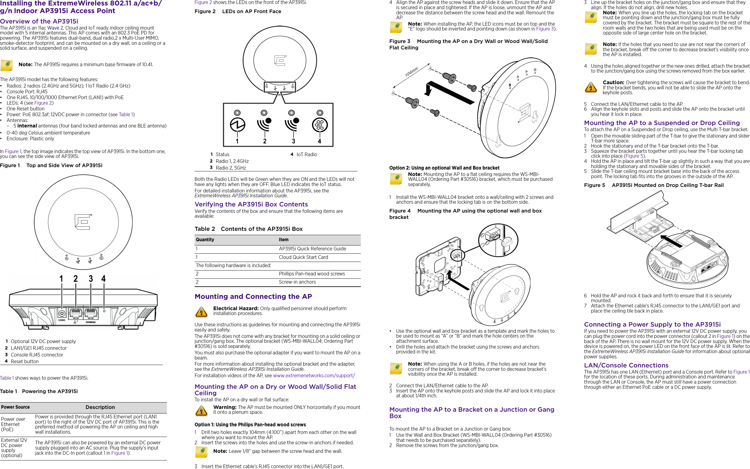
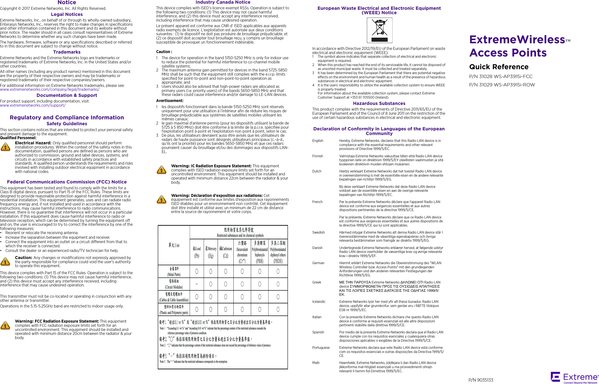
Extreme Networks AP3915I Wireless 802.11 a/ac+b/g/n Indoor Access Point User Manual AP3915i

Extreme Networks, Inc. Wireless 802.11 a/ac+b/g/n Indoor Access Point AP3915i

User Manual AP3915i

Installing the ExtremeWireless 802.11 a/ac+b/g/n Indoor AP3915i Access PointOverview of the AP3915iThe AP3915i is an 11ac Wave 2, Cloud and IoT ready indoor ceiling mount model with 5 internal antennas. This AP comes with an 802.3 PoE PD for powering. The AP3915i features dual-band, dual radio,2 x Multi-User MIMO, smoke-detector footprint, and can be mounted on a dry wall, on a ceiling or a solid surface, and suspended on a ceiling. The AP3915i model has the following features:• Radios: 2 radios (2.4GHz and 5GHz); 1 IoT Radio (2.4 GHz)•Console Port: RJ45• One RJ45, 10/100/1000 Ethernet Port (LAN1) with PoE •LEDs: 4 (see Figure 2)•One Reset button • Power: PoE 802.3af; 12VDC power in connector (see Table 1)• Antennas:–5 internal antennas (four band locked antennas and one BLE antenna)• 0-40 deg Celsius ambient temperature • Enclosure: Plastic onlyIn Figure 1, the top image indicates the top view of AP3915i. In the bottom one, you can see the side view of AP3915i. Figure 1  Top and Side View of AP3915iTable 1 shows ways to power the AP3915i.Table 1 Powering the AP3915i Note: The AP3915i requires a minimum base firmware of 10.41.1Optional 12V DC power supply2LAN1/GE1 RJ45 connector3Console RJ45 connector4Reset buttonPower Source DescriptionPower over Ethernet (PoE)Power is provided through the RJ45 Ethernet port (LAN1 port) to the right of the 12V DC port of AP3915i. This is the preferred method of powering the AP on ceiling and high wall installations.External 12V DC power supply (optional)The AP3915i can also be powered by an external DC power supply plugged into an AC source. Plug the supply’s input jack into the DC-In port (callout 1 in Figure 1). Figure 2 shows the LEDs on the front of the AP3915i. Figure 2  LEDs on AP Front FaceBoth the Radio LEDs will be Green when they are ON and the LEDs will not have any lights when they are OFF. Blue LED indicates the IoT status.For detailed installation information about the AP3915i, see the ExtremeWireless AP3915i Installation Guide.Verifying the AP3915i Box ContentsVerify the contents of the box and ensure that the following items are available:Mounting and Connecting the APUse these instructions as guidelines for mounting and connecting the AP3915i easily and safely. The AP3915i does not come with any bracket for mounting on a solid ceiling or junction/gang box. The optional bracket (WS-MBI-WALL04; Ordering Part #30516) is sold separately. You must also purchase the optional adapter if you want to mount the AP on a beam.For more information about installing the optional bracket and the adapter, see the ExtremeWireless AP3915i Installation Guide.For installation videos of the AP, see www.extremenetworks.com/support/Mounting the AP on a Dry or Wood Wall/Solid Flat CeilingTo install the AP on a dry wall or flat surface:Option 1: Using the Philips Pan-head wood screws1 Drill two holes exactly 104mm (4.100”) apart from each other on the wall where you want to mount the AP.2 Insert the screws into the holes and use the screw-in anchors if needed.3 Insert the Ethernet cable’s RJ45 connector into the LAN1/GE1 port. 1Status  4IoT Radio2Radio 1, 2.4GHz3Radio 2, 5GHzTable 2 Contents of the AP3915i BoxQuantity Item1 AP3915i Quick Reference Guide1 Cloud Quick Start CardThe following hardware is included:2 Phillips Pan-head wood screws2 Screw-in anchorsElectrical Hazard: Only qualified personnel should perform installation procedures.Warning: The AP must be mounted ONLY horizontally if you mount it onto a plenum space. Note: Leave 1/8” gap between the screw head and the wall.4 Align the AP against the screw heads and slide it down. Ensure that the AP is secured in place and tightened. If the AP is loose, unmount the AP and decrease the distance between the screw head and the wall. Remount the AP. Figure 3  Mounting the AP on a Dry Wall or Wood Wall/Solid Flat CeilingOption 2: Using an optional Wall and Box bracket1 Install the WS-MBI-WALL04 bracket onto a wall/ceiling with 2 screws and anchors and ensure that the locking tab is on the bottom side.Figure 4  Mounting the AP using the optional wall and box bracket• Use the optional wall and box bracket as a template and mark the holes to be used to mount as “A” or “B” and mark the hole centers on the attachment surface.• Drill the holes and attach the bracket using the screws and anchors provided in the kit. 2 Connect the LAN/Ethernet cable to the AP. 3 Insert the AP onto the keyhole posts and slide the AP and lock it into place at about 1/4th inch.Mounting the AP to a Bracket on a Junction or Gang BoxTo mount the AP to a Bracket on a Junction or Gang box:1 Use the Wall and Box Bracket (WS-MBI-WALL04 (Ordering Part #30516) that needs to be purchased separately). 2 Remove the screws from the junction/gang box. Note: When installing the AP, the LED icons must be on top and the “E” logo should be inverted and pointing down (as shown in Figure 3).Note: Mounting the AP to a flat ceiling requires the WS-MBI-WALL04 (Ordering Part #30516) bracket, which must be purchased separately. Note: When using the A or B holes, if the holes are not near the corners of the bracket, break off the corner to decrease bracket’s visibility once the AP is installed.3 Line up the bracket holes on the junction/gang box and ensure that they align. If the holes do not align, drill new holes.4 Using the holes aligned together or the new ones drilled, attach the bracket to the junction/gang box using the screws removed from the box earlier. 5 Connect the LAN/Ethernet cable to the AP. 6 Align the keyhole slots and posts and slide the AP onto the bracket until you hear it lock in place. Mounting the AP to a Suspended or Drop CeilingTo attach the AP on a Suspended or Drop ceiling, use the Multi T-bar bracket.1 Open the movable sliding part of the T-bar to give the stationary and slider T-bar more space. 2 Hook the stationary end of the T-bar bracket onto the T-bar.3 Squeeze the bracket parts together until you hear the T-bar locking tab click into place (Figure 5). 4 Hold the AP in place and tilt the T-bar up slightly in such a way that you are holding the stationary and movable sides of the bracket. 5 Slide the T-bar ceiling mount bracket base into the back of the access point. The locking tab fits into the grooves in the outside of the AP.Figure 5  AP3915i Mounted on Drop Ceiling T-bar Rail 6 Hold the AP and rock it back and forth to ensure that it is securely mounted.7 Attach the Ethernet cable’s RJ45 connector to the LAN1/GE1 port and place the ceiling tile back in place.Connecting a Power Supply to the AP3915iIf you need to power the AP3915i with an external 12V DC power supply, you can plug the power cord into the power connector (callout 2 in Figure 1) on the back of the AP. There is no wall mount for the 12V DC power supply. When the device is powered on, the power LED on the front face of the AP is lit. Refer to the ExtremeWireless AP3915i Installation Guide for information about optional power supplies.LAN/Console ConnectionsThe AP3915i has one LAN (Ethernet) port and a Console port. Refer to Figure 1 for the location of these ports. During administration and maintenance through the LAN or Console, the AP must still have a power connection through either an Ethernet PoE cable or a DC power supply.Note: When you line up the holes, the locking tab on the bracket must be pointing down and the junction/gang box must be fully covered by the bracket. The bracket must be square to the rest of the room walls and the two holes that are being used must be on the opposite side of large center hole on the bracket.Note: If the holes that you need to use are not near the corners of the bracket, break off the corner to decrease bracket’s visibility once the AP is installed.Caution: Over tightening the screws will cause the bracket to bend. If the bracket bends, you will not be able to slide the AP onto the keyhole posts.
ExtremeWirelessTM Access PointsQuick ReferenceP/N 31028 WS-AP3915i-FCCP/N 31029 WS-AP3915i-ROWNotice Copyright © 2017 Extreme Networks, Inc. All Rights Reserved.Legal NoticesExtreme Networks, Inc., on behalf of or through its wholly-owned subsidiary, Enterasys Networks, Inc., reserves the right to make changes in specifications and other information contained in this document and its website without prior notice. The reader should in all cases consult representatives of Extreme Networks to determine whether any such changes have been made.The hardware, firmware, software or any specifications described or referred to in this document are subject to change without notice.TrademarksExtreme Networks and the Extreme Networks logo are trademarks or registered trademarks of Extreme Networks, Inc. in the United States and/or other countries. All other names (including any product names) mentioned in this document are the property of their respective owners and may be trademarks or registered trademarks of their respective companies/owners.For additional information on Extreme Networks trademarks, please see: www.extremenetworks.com/company/legal/trademarks/Documentation & SupportFor product support, including documentation, visit: www.extremenetworks.com/support/ Regulatory and Compliance InformationSafety GuidelinesThis section contains notices that are intended to protect your personal safety and prevent damage to the equipment.Qualified Personnel:Federal Communications Commission (FCC) Notice This equipment has been tested and found to comply with the limits for a Class B digital device, pursuant to Part 15 of the FCC Rules. These limits are designed to provide reasonable protection against harmful interference in a residential installation. This equipment generates, uses and can radiate radio frequency energy and, if not installed and used in accordance with the instructions, may cause harmful interference to radio communications. However, there is no guarantee that interference will not occur in a particular installation. If this equipment does cause harmful interference to radio or television reception, which can be determined by turning the equipment off and on, the user is encouraged to try to correct the interference by one of the following measures:• Reorient or relocate the receiving antenna.• Increase the separation between the equipment and receiver.• Connect the equipment into an outlet on a circuit different from that to which the receiver is connected.• Consult the dealer or an experienced radio/TV technician for help.This device complies with Part 15 of the FCC Rules. Operation is subject to the following two conditions: (1) This device may not cause harmful interference, and (2) this device must accept any interference received, including interference that may cause undesired operation.This transmitter must not be co-located or operating in conjunction with any other antenna or transmitter.Operations in the 5.15-5.25GHz band are restricted to indoor usage only.Electrical Hazard: Only qualified personnel should perform installation procedures. Within the context of the safety notes in this documentation, qualified persons are defined as persons who are authorized to commission, ground and label devices, systems, and circuits in accordance with established safety practices and standards. A qualified person understands the requirements and risks involved with installing outdoor electrical equipment in accordance with national codes.Caution: Any changes or modifications not expressly approved by the party responsible for compliance could void the user's authority to operate this equipment.Warning: FCC Radiation Exposure Statement: This equipment complies with FCC radiation exposure limits set forth for an uncontrolled environment. This equipment should be installed and operated with minimum distance 20cm between the radiator & your body.Industry Canada Notice This device complies with ISED’s licence-exempt RSSs. Operation is subject to the following two conditions: (1) This device may not cause harmful interference, and (2) this device must accept any interference received, including interference that may cause undesired operation.Le présent appareil est conforme aux CNR d’ ISED applicables aux appareils radio exempts de licence. L’exploitation est autorisée aux deux conditions suivantes : (1) le dispositif ne doit pas produire de brouillage préjudiciable, et (2) ce dispositif doit accepter tout brouillage reçu, y compris un brouillage susceptible de provoquer un fonctionnement indésirable. Caution :1 The device for operation in the band 5150-5250 MHz is only for indoor use to reduce the potential for harmful interference to co-channel mobile satellite systems;2 The maximum antenna gain permitted for devices in the band 5725-5850 MHz shall be such that the equipment still complies with the e.i.r.p. limits specified for point-to-point and non-point-to-point operation as appropriate; and 3 Users should also be advised that high-power radars are allocated as primary users (i.e. priority users) of the bands 5650-5850 MHz and that these radars could cause interference and/or damage to LE-LAN devices.Avertissement:1 les dispositifs fonctionnant dans la bande 5150-5250 MHz sont réservés uniquement pour une utilisation à l’intérieur afin de réduire les risques de brouillage préjudiciable aux systèmes de satellites mobiles utilisant les mêmes canaux;2 le gain maximal d'antenne permis (pour les dispositifs utilisant la bande de 5725 à 5 850 MHz) doit être conforme à la limite de la p.i.r.e. spécifiée pour l'exploitation point à point et l’exploitation non point à point, selon le cas; 3 De plus, les utilisateurs devraient aussi être avisés que les utilisateurs de radars de haute puissance sont désignés utilisateurs principaux (c.-à-d., qu’ils ont la priorité) pour les bandes 5650-5850 MHz et que ces radars pourraient causer du brouillage et/ou des dommages aux dispositifs LAN-EL.Warning: IC Radiation Exposure Statement: This equipment complies with ISED radiation exposure limits set forth for an uncontrolled environment. This equipment should be installed and operated with minimum distance 22cm between the radiator & your body.Warning: Déclaration d'exposition aux radiations: Cet équipement est conforme aux limites d'exposition aux rayonnements ISED établies pour un environnement non contrôlé. Cet équipement doit être installé et utilisé avec un minimum de 22 cm de distance entre la source de rayonnement et votre corps.European Waste Electrical and Electronic Equipment (WEEE) NoticeIn accordance with Directive 2012/19/EU of the European Parliament on waste electrical and electronic equipment (WEEE):1 The symbol above indicates that separate collection of electrical and electronic equipment is required.2 When this product has reached the end of its serviceable life, it cannot be disposed of as unsorted municipal waste. It must be collected and treated separately.3 It has been determined by the European Parliament that there are potential negative effects on the environment and human health as a result of the presence of hazardous substances in electrical and electronic equipment.4 It is the users’ responsibility to utilize the available collection system to ensure WEEE is properly treated.For information about the available collection system, please contact Extreme Customer Support at +353 61 705500 (Ireland).Hazardous SubstancesThis product complies with the requirements of Directive 2011/65/EU of the European Parliament and of the Council of 8 June 2011 on the restriction of the use of certain hazardous substances in electrical and electronic equipment.Declaration of Conformity in Languages of the European CommunityEnglish Hereby, Extreme Networks, declares that this Radio LAN device is in compliance with the essential requirements and other relevant provisions of Directive 1999/5/EC.Finnish Valmistaja Extreme Networks vakuuttaa täten että Radio LAN device tyyppinen laite on direktiivin 1999/5/EY oleellisten vaatimusten ja sitä koskevien direktiivin muiden ehtojen mukainen.Dutch Hierbij verklaart Extreme Networks dat het toestel Radio LAN device in overeenstemming is met de essentiële eisen en de andere relevante bepalingen van richtlijn 1999/5/EG. Bij deze verklaart Extreme Networks dat deze Radio LAN device voldoet aan de essentiële eisen en aan de overige relevante bepalingen van Richtlijn 1999/5/EC.French Par la présente Extreme Networks déclare que l'appareil Radio LAN device est conforme aux exigences essentielles et aux autres dispositions pertinentes de la directive 1999/5/CE. Par la présente, Extreme Networks déclare que ce Radio LAN device est conforme aux exigences essentielles et aux autres dispositions de la directive 1999/5/CE qui lui sont applicables.Swedish Härmed intygar Extreme Networks att denna Radio LAN device står I överensstämmelse med de väsentliga egenskapskrav och övriga relevanta bestämmelser som framgår av direktiv 1999/5/EG. Danish Undertegnede Extreme Networks erklærer herved, at følgende udstyr Radio LAN device overholder de væsentlige krav og øvrige relevante krav i direktiv 1999/5/EF.German Hiermit erklärt Extreme Networks die Übereinstimmung des "WLAN Wireless Controller bzw. Access Points" mit den grundlegenden Anforderungen und den anderen relevanten Festlegungen der Richtlinie 1999/5/EG.Greek ΜΕ ΤΗΝ ΠΑΡΟΥΣΑ Extreme Networks ∆ΗΛΩΝΕΙ ΟΤΙ Radio LAN device ΣΥΜΜΟΡΦΩΝΕΤΑΙ ΠΡΟΣ ΤΙΣ ΟΥΣΙΩ∆ΕΙΣ ΑΠΑΙΤΗΣΕΙΣ ΚΑΙ ΤΙΣ ΛΟΙΠΕΣ ΣΧΕΤΙΚΕΣ ∆ΙΑΤΑΞΕΙΣ ΤΗΣ Ο∆ΗΓΙΑΣ 1999/5/ΕΚ.Icelandic Extreme Networks lysir her med yfir að thessi bunadur, Radio LAN device, uppfyllir allar grunnkrofur, sem gerdar eru i R&TTE tilskipun ESB nr 1999/5/EC.Italian Con la presente Extreme Networks dichiara che questo Radio LAN device è conforme ai requisiti essenziali ed alle altre disposizioni pertinenti stabilite dalla direttiva 1999/5/CE.Spanish Por medio de la presente Extreme Networks declara que el Radio LAN device cumple con los requisitos esenciales y cualesquiera otras disposiciones aplicables o exigibles de la Directiva 1999/5/CE.Portuguese Extreme Networks declara que este Radio LAN device está conforme com os requisitos essenciais e outras disposições da Directiva 1999/5/CE. Malti Hawnhekk, Extreme Networks, jiddikjara li dan Radio LAN device jikkonforma mal-htigijiet essenzjali u ma provvedimenti ohrajn relevanti li hemm fid-Dirrettiva 1999/5/EC.P/N 9035133

Navigation menu