Extreme Networks AP7612 Wall plate 802.11ac Wave 2, 2x2 2, BT, Internal Antenna User Manual WS AP3965 Wireless Access Points Quick Reference
Extreme Networks, Inc. Wall plate 802.11ac Wave 2, 2x2 2, BT, Internal Antenna WS AP3965 Wireless Access Points Quick Reference
User Manual
Installing the ExtremeWireless Indoor AP-
7612 Access Point
Overview of the AP-7612
The AP-7612 is a wall plate 11ac Wave 2 AP that lets you
extend your Wireless LAN and deploy local WiFi while still
providing extension for wired clients from the same
Ethernet jack. This fully-featured access point plugs into
existing Ethernet cabled wall plates. The AP provides
application visibility and control and policy support over
dual integrated radios and a Bluetooth Low Energy (BLE)
radio. AP-7612 will also include a second Gigabit Ethernet
port with PoE sourcing capability. The PSE port provides
PoE (802.3af) which can be used to power devices such as
IP Phones. The AP-7612 is designed with five single-band
internal antennas for indoor use only.
The AP-7612 model has the following specifications:
• Primarily designed to support wall, single and dual-gang
box installation.
• Radios: Two concurrent WiFi radios (2.4 GHz and 5 GHz)
and one additional radio that can operate as Bluetooth or
802.15.4.
• LEDs: 3 (Figure 2)
• Power: 802.3at (PoE+) compliant for full functionality.
802.3af is supported with reduced functionality.
• The AP-7612 supports the 802.11ac and 802.11n wireless
standards, with full backward compatibility with legacy
802.11abg.
• The AP-7612 interoperates fully with Wireless LAN,
including support for VoWLAN, branch office mode,
guest services, RTLS, availability, and mobility.
For detailed installation information about the AP-7612, see
the ExtremeWireless AP-7612 Installation Guide.
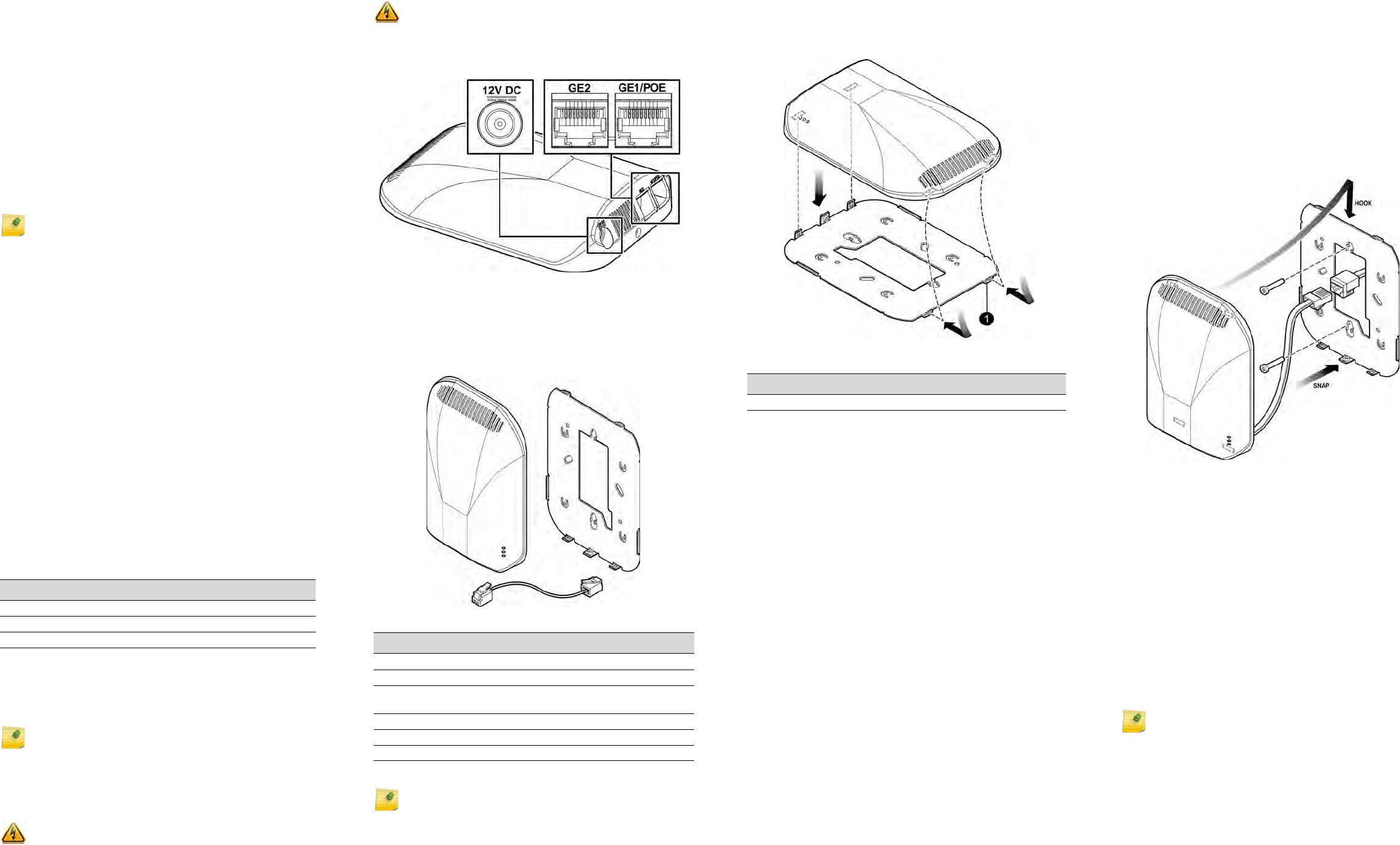
Uplink and Power Connections
The AP-7612 uses Power over Ethernet (PoE) as follows:
The AP has two client ports (GE1/POE and GE2), where:
• GE1/POE port is the system connection.
• GE2 port is used for connecting to an IP Phone.
The GE2 port let users connect wired clients, such as
laptops and printers, to the network only when the AP is
taken off the bracket.
Note: The AP-7612 requires a minimum base firmware of
WiNG 5.9.1.
Table 1 Power Sources
Input PoE Power Sourcing on GE2
GE1 PoE 802.3at 15.4 Watts.
GE1 PoE 802.3af Not available.
12V DC Not available.
Note: Both the client ports (GE1/POE and GE2) are not
accessible when the AP is mounted on to a bracket.
Caution: The AP should be taken off the bracket only by the
owner or someone who is trained to perform the task
professionally.
Figure 1 Power Connections
Verifying the AP-7612 Box Contents
Verify the contents of the box as listed in the following
table:
Figure 2 AP-7612 Box Contents
Mounting and Connecting the AP-7612
Use these instructions as guidelines for mounting and
connecting the AP-7612 easily and safely.
Attach the AP-7612 to an indoor wall or junction/gang box.
The wall plate bracket is included with the AP box contents.
Warning: To reduce potential safety issues, only the AC
adapter provided with the product, a replacement AC
adapter provided by agency, or an AC adapter purchased
as an accessory from agency should be used with the
product.
Table 2 Contents of the AP-7612 Box
Quantity Item
1AP-7612 Quick Reference
1AP-7612-680B30-xx
1 Wall/Junction box/Gang box mounting bracket
(includes Security Torx screw)
The following hardware is included:
1 100mm twisted pair RJ45 Flat Cable
1 Security Torx screw (size 0.45X6)
Note: Before mounting the AP-7612, read the Safety
Guidelines section.
The AP mounting bracket is designed for single and dual-
gang box configurations. For wider installations, you can
either adapt the existing bracket or opt to wall-mount the
AP.
Figure 3 Mounting Bracket
Mounting the AP-7612 to a Wall
1 Using the mounting bracket (Figure 3) as a guide,
choose a location where it is feasible to place the AP’s
center. The location must allow the LAN cables to come
out of the wall within the large rectangular hole. Place
the bracket against the wall. (The captive screw will be
used to lock the AP in place.) Decide which two holes to
use to mount the bracket. We recommend using the two
holes at the top and the bottom center of the opening.
At a minimum, use two holes on opposite sides of the
large center opening.
2 Mark the two hole centers.
3 Drill the two holes using the appropriate drill bit size. For
drywall/plasterboard walls, drill two holes using a drill bit
of 1/4” or 6mm diameter.
4 Attach two screws so there is about 1/4” between the
screw head and the wall. For drywall/plasterboard walls,
insert the anchors into the wall first and then insert the
screws into the anchors.
5 Insert the bracket over the screw heads and slide the
bracket in such a way that both screws get attached to
the bracket.
6 Tighten the screws to secure the bracket in its place.
Torque the screws to 9.0 in-lbs.
7 Connect the LAN1 (GE1/POE) cable and the LAN2 (GE2)
cable (if applicable) from the wall and attach the AP to
the mounting bracket, as described below.
Mounting to a Junction/Gang Box
1 Place the bracket over the junction box with the two tabs
inserted into the AP (Figure 3) and keep it oriented
toward the top. The flat surface of the bracket should be
kept against the wall.
Tab le 3
Number Description
1 AP mounting tabs
2 Align two of the bracket holes with two of the box’s
holes. The two holes should be on opposite sides of the
larger center opening. Use bracket holes that are closest
to the center of the bracket. Make sure that the entire
box is covered by the bracket.
3 Using the two pan head machine screws, attach the
bracket to the box using the aligned holes. Torque the
screws to 9.0 in-lbs.
4 Connect the LAN1 (GE1/POE) cable from the wall and
attach the AP to the mounting bracket. Connect the
LAN2 (GE2) cable (if applicable) after attaching the AP
to the mounting bracket, as described below.
Figure 4 Mounting the AP
Connecting the AP to the Network
Connect the RJ45 Flat Cable to the GE1/PoE port and pass
the cable through the back of the unit. Connect the other
end of the cable to the Building LAN outlet.
Mounting the AP to the Bracket
1 Stuff any extra GE1 cable into the wall/box (Figure 3).
2 Keep the bracket at an angle and insert the two tabs at
the top of the bracket into the AP (Figure 3).
3 Rotate the AP (on the tabs), until it clips to the other side
of the bracket at the bottom of the AP (the side where
the cable enters).
4 Attach and tighten the security screw to the bottom of
the AP (as shown in Figure 3) and make sure that the AP
is attached to the bracket. Torque the screw to 7.0 in-lbs.
Note: If you are using the optional 12 VDC-IN adapter
instead of PoE on GE1, then fully insert the friction fit
connector into the AP. Plug the AP into an AC receptacle.
ExtremeWirelessTM
Access Points
Quick Reference
P/N 37101 AP-7612-680B30-US
P/N 37102 AP-7612-680B30-WR
Notice
Copyright © 2017 Extreme Networks, Inc. All Rights Reserved.
Legal Notices
Extreme Networks, Inc. reserves the right to make changes in specifications
and other information contained in this document and its website without
prior notice. The reader should in all cases consult representatives of
Extreme Networks to determine whether any such changes have been
made.
The hardware, firmware, software or any specifications described or referred
to in this document are subject to change without notice.
Trademarks
Extreme Networks and the Extreme Networks logo are trademarks or
registered trademarks of Extreme Networks, Inc. in the United States and/or
other countries.
All other names (including any product names) mentioned in this document
are the property of their respective owners and may be trademarks or
registered trademarks of their respective companies/owners.
For additional information on Extreme Networks trademarks, please see:
www.extremenetworks.com/company/legal/trademarks/
Documentation & Support
For product support, including documentation, visit:
www.extremenetworks.com/support/
Regulatory and Compliance Information
Federal Communications Commission (FCC) Notice:
This equipment has been tested and found to comply with the limits for a
Class B digital device, pursuant to Part 15 of the FCC Rules. These limits are
designed to provide reasonable protection against harmful interference in a
residential installation. This equipment generates, uses and can radiate radio
frequency energy and, if not installed and used in accordance with the
instructions, may cause harmful interference to radio communications.
However, there is no guarantee that interference will not occur in a
particular installation. If this equipment does cause harmful interference to
radio or television reception, which can be determined by turning the
equipment off and on, the user is encouraged to try to correct the
interference by one of the following measures:
• Reorient or relocate the receiving antenna.
• Increase the separation between the equipment and receiver.
• Connect the equipment into an outlet on a circuit different from that to
which the receiver is connected.
• Consult the dealer or an experienced radio/TV technician for help.
.This device complies with Part 15 of the FCC Rules. Operation is subject to
the following two conditions: (1) This device may not cause harmful
interference, and (2) this device must accept any interference received,
including interference that may cause undesired operation.
For product available in the USA/Canada market, only channel 1~11 can be
operated. Selection of other channels is not possible.
This device is going to be operated in 5.15~5.25GHz frequency range, it is
restricted in indoor environment only.
This device is restricted for indoor use.
Industry Canada Notice:
This device complies with Industry Canada license-exempt RSS standard(s).
Operation is subject to the following two conditions: (1) this device may not
cause interference, and (2) this device must accept any interference,
including interference that may cause undesired operation of the device.
Le présent appareil est conforme aux CNR d'Industrie Canada applicables
aux appareils radio exempts de licence. L'exploitation est autorisée aux deux
conditions suivantes : (1) l'appareil ne doit pas produire de brouillage, et (2)
l'utilisateur de l'appareil doit accepter tout brouillage radioélectrique subi,
même si le brouillage est susceptible d'en compromettre le fonctionnement.
Caution:
1 For product available in the USA/Canada market, only channel 1~11 can be
operated. Selection of other channels is not possible.
2 Dynamic Frequency Selection (DFS) for devices operating in the bands
5250- 5350 MHz, 5470-5600 MHz and 5650-5725 MHz.
3 The device for operation in the band 5150-5250 MHz is only for indoor use
to reduce the potential for harmful interference to co-channel mobile
satellite systems.
4 The maximum antenna gain permitted for devices in the bands 5250-5350
MHz and 5470-5725 MHz shall be such that the equipment still complies
with the e.i.r.p. limit.
Caution: Any changes or modifications not expressly
approved by the party responsible for compliance could
void the user's authority to operate this equipment
Warning: FCC Radiation Exposure Statement: This
equipment complies with FCC radiation exposure limits set forth for
an uncontrolled environment. This equipment should be installed
and operated with minimum distance 22cm between the radiator &
your body.
5 The maximum antenna gain permitted for devices in the band 5725-5850
MHz shall be such that the equipment still complies with the e.i.r.p. limits
specified for point-to-point and non-point-to-point operation as
appropriate.
6 For indoor use only.
Avertissement:
1 Pour les produits disponibles aux États-Unis / Canada du marché, seul le
canal 1 à 11 peuvent être exploités. Sélection d'autres canaux n'est pas
possible.
2 Sélection dynamique de fréquences (DFS) pour les dispositifs
fonctionnant dans les bandes 5250-5350 MHz, 5470-5600 MHz et 5650-
5725 MHz.
3 Les dispositifs fonctionnant dans la bande 5150-5250 MHz sont
réservés uniquement pour une utilisation à l’intérieur afin de
réduire les risques de brouillage préjudiciable aux systèmes de
satellites mobiles utilisant les mêmes canaux;
4 le gain maximal d’antenne permis pour les dispositifs utilisant les bandes
5250-5350 MHz et 5470-5725 MHz doit se conformer à la limite de p.i.r.e.
5 le gain maximal d’antenne permis (pour les dispositifs utilisant la bande
5725-5850 MHz) doit se conformer à la limite de p.i.r.e. spécifiée pour
l’exploitation point à point et non point à point, selon le cas.
6 Pour une utilisation en intérieur uniquement.
For Mobile Device Usage
Safety Guidelines
This section contains notices that you must adhere to ensure your personal
safety and to prevent any damage to the equipment.
European Waste Electrical and Electronic
Equipment (WEEE) Notice
In accordance with Directive 2012/19/EU of the European Parliament on
waste electrical and electronic equipment (WEEE):
1 The symbol above indicates that separate collection of electrical and
electronic equipment is required.
2 When this product has reached the end of its serviceable life, it cannot be
disposed of as unsorted municipal waste. It must be collected and treated
separately.
3 It has been determined by the European Parliament that there are
potential negative effects on the environment and human health as a
result of the presence of hazardous substances in electrical and electronic
equipment.
4 It is the users’ responsibility to utilize the available collection system to
ensure WEEE is properly treated.
For information about the available collection system, please contact
Extreme Customer Support at 353 61 705500 (Ireland).
CE Statement for Mobile Device Usage
All operational modes:
2.4GHz: 802.11b, 802.11g, 802.11n (HT20), 802.11n (HT40), 802.11ac (VHT20),
802.11ac (VHT40), Bluetooth(BR/EDR, LE)
5GHz: 802.11a, 802.11n (HT20), 802.11n (HT40), 802.11ac (VHT20), 802.11ac
(VHT40), 802.11ac (VHT80)
The frequency and the maximum transmitted power in EU are listed below:
2412-2472MHz: 19.84 dBm
2402-2480MHz (BR/EDR): 9.99 dBm
2402-2480MHz (LE): 9.63 dBm
5180-5320MHz: 22.93 dBm
5500-5700MHz: 29.97 dBm
Warning: IC Radiation Exposure Statement: This equipment
complies with IC RSS-102 radiation exposure limits set forth for an
uncontrolled environment. This equipment should be installed and
operated with minimum distance 24cm between the radiator & your
body.
Warning: Déclaration d'exposition aux radiations: Cet
équipement est conforme aux limites d'exposition aux
rayonnements IC établies pour un environnement non contrôlé. Cet
équipement doit être installé et utilisé avec un minimum de 24 cm
de distance entre la source de rayonnement et votre corps.
Caution: The unit and all interconnected equipment must be
installed indoors within the same building, including all PoE-
powered network connections as described by Environment A of
the IEEE 802.3af standard.
Warning: MPE Radiation Exposure Statement: This
equipment complies with EU radiation exposure limits set forth for
an uncontrolled environment. This equipment should be installed
and operated with minimum distance 20cm between the radiator &
your body.
The device is restricted to indoor use only when operating in the 5150 to
5350 MHz frequency range.
Selling Countries:
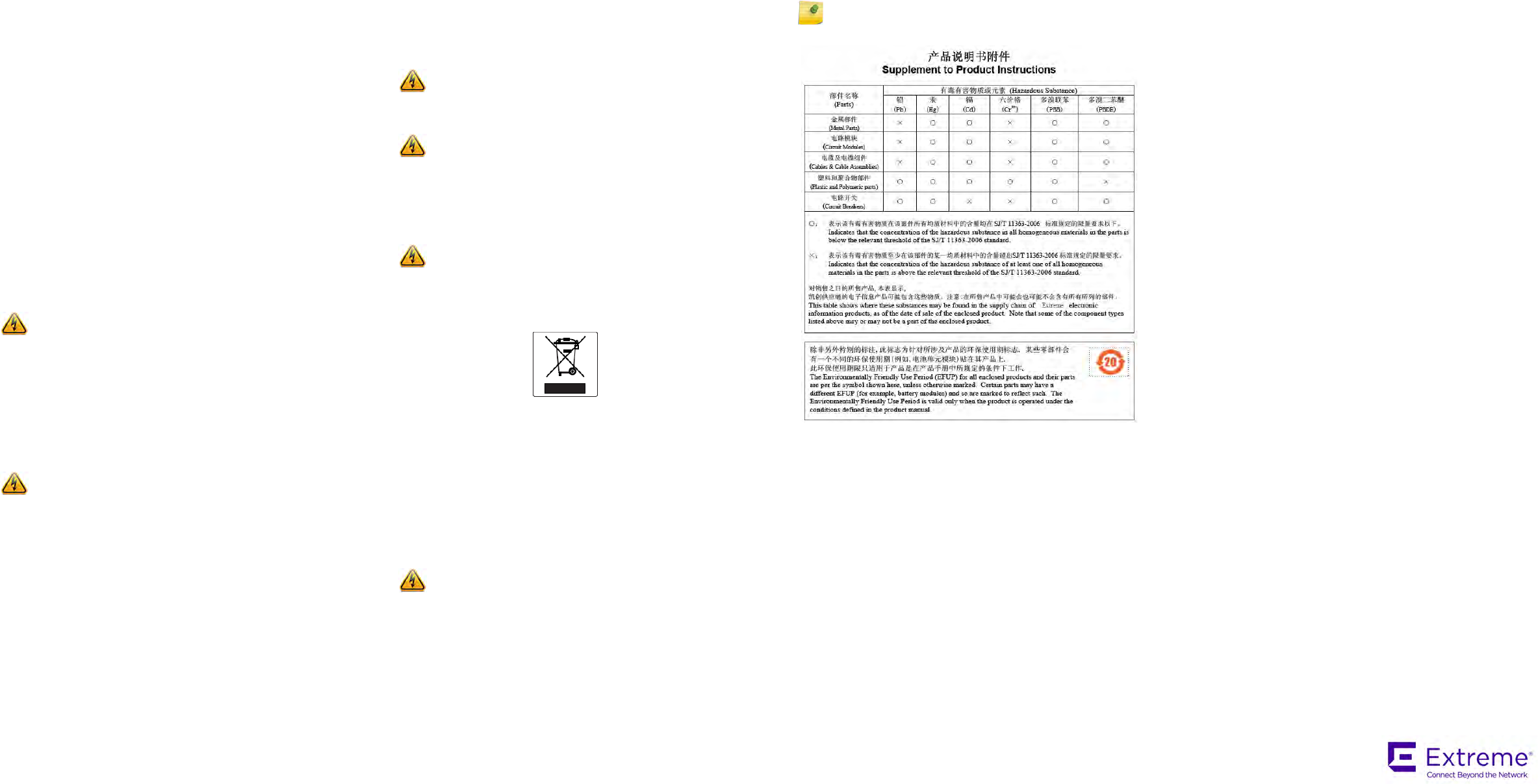
Hazardous Substances
This product complies with the requirements of Directive 2011/65/EU of the
European Parliament and of the Council of 8 June 2011 on the restriction of
the use of certain hazardous substances in electrical and electronic
equipment.
Declaration of Conformity in Languages of the European Community
Hereby, Extreme Networks, Inc. declares that the radio equipment type
Wireless LAN Access Point is in compliance with Directive 1999/5/EC. The
full text of the EU declaration of conformity is available at the following
Internet address: http://www.extremenetworks.com/
NCC Statement
低功率電波輻射性電機管理辦法
第十二條 經型式認證合格之低功率射頻電機,非經許
可,公司、商號或使用者均不得擅自變更頻
率、加大功率或變更原設計之特性及功能。
第十四條 低功率射頻電機之使用不得影響飛航安全及
干擾合法通信;經發現有干擾現象時,應立
即停用,並改善至無干擾時方得繼續使用。
前項合法通信,指依電信法規定作業之無線
電通信。
低功率射頻電機須忍受合法通信或工業、科
學及醫療用電波輻射性電機設備之干擾。
在5.25-5.35 秭赫頻帶內操作之無線資訊傳輸設備,限
於室內使用。
電磁波曝露量 MPE 標準值 1mW/cm2,送測產品實測值
為0.315mW/cm2
AT BE BG HR CY CZ DK
EE FI FR DE EL HU IE
IT LV LT LU MT NL PL
PT RO SK SI ES SE UK
Note: Changes or modifications made to this device which are not
expressly approved by the party responsible for compliance could
void the user’s authority to operate the equipment.
P/N 9035057