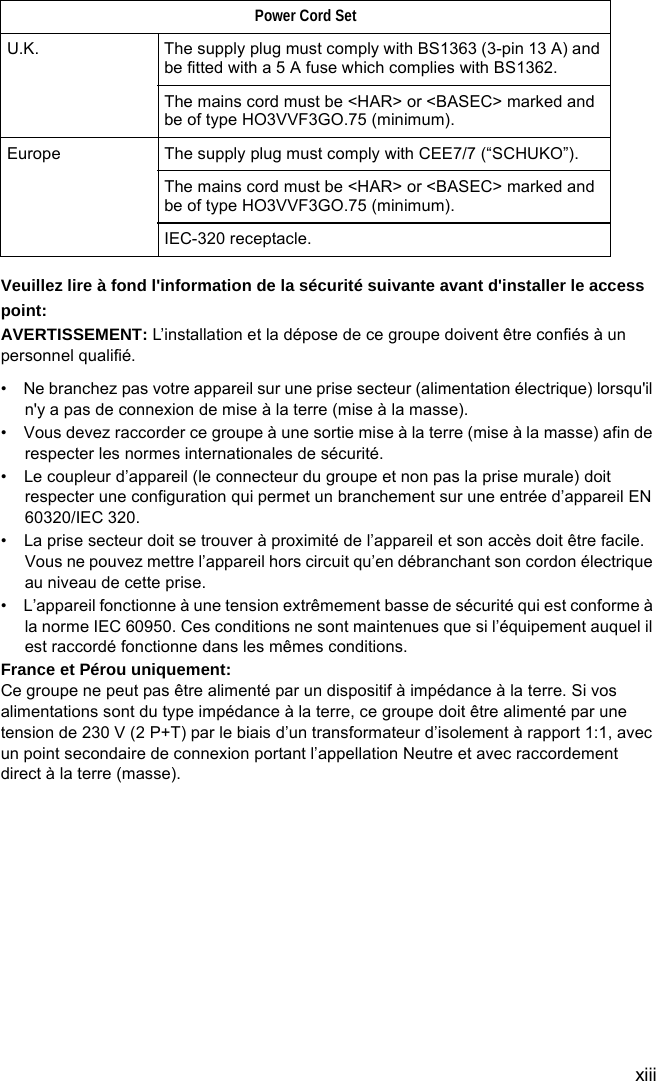
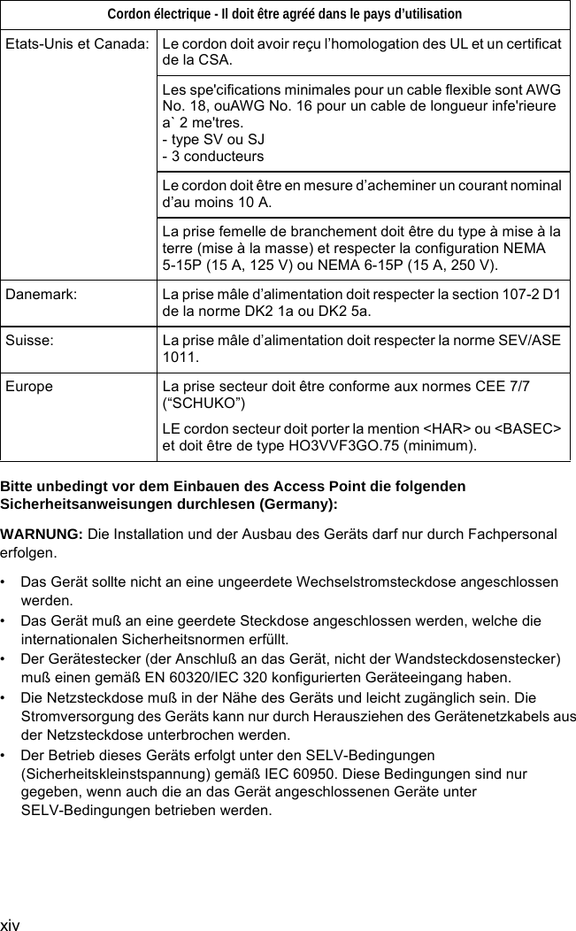
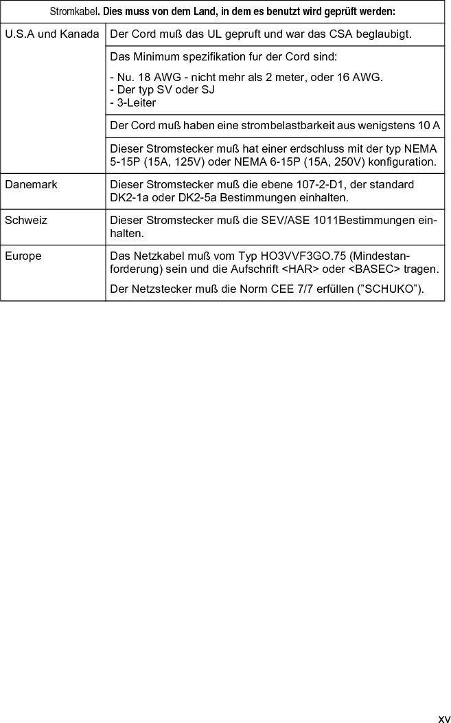
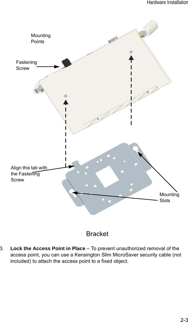
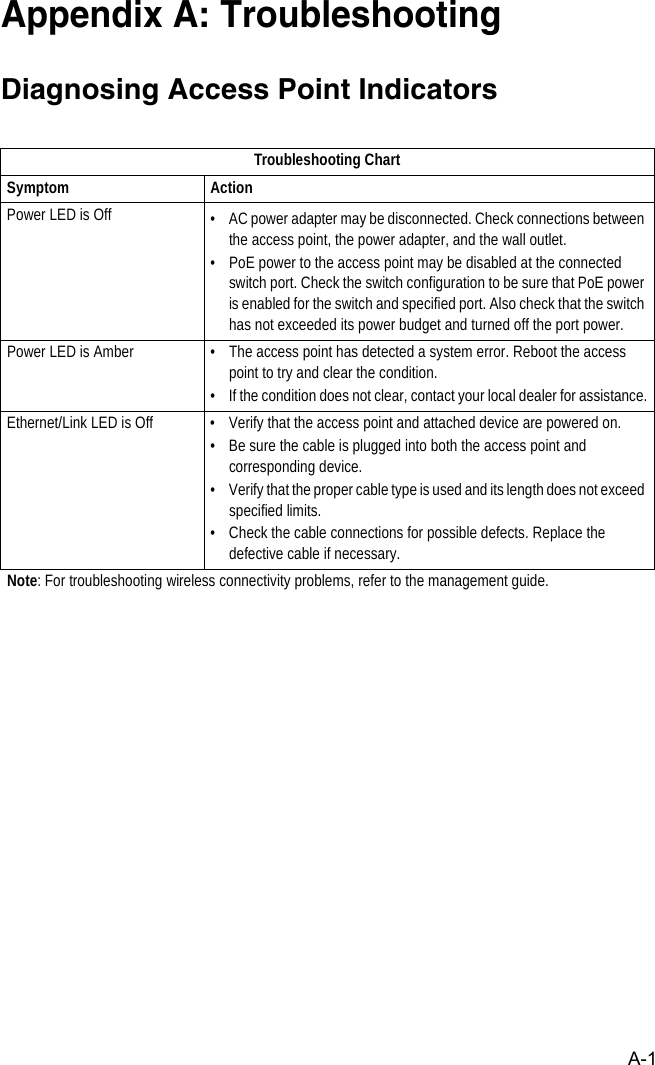
Extreme Networks RBT4102 Multi-Channel Access Point User Manual EAP6626A IG 60

Extreme Networks, Inc. Multi-Channel Access Point EAP6626A IG 60

Contents

Users Manual

P/N 9034148-06RoamAboutRBT-4102, RBT-4102-BG, and RBT-4102-EU2.4 GHz / 5 GHz Wireless Access PointInstallation Guide
iNoticeENTERASYS NETWORKS reserves the right to make changes in specifications and other information contained in this document and its web site without prior notice. The reader should in all cases consult ENTERASYS NETWORKS to determine whether any such changes have been made.The hardware, firmware, or software described in this document is subject to change without notice.IN NO EVENT SHALL ENTERASYS NETWORKS BE LIABLE FOR ANY INCIDENTAL, INDIRECT, SPECIAL, OR CONSEQUENTIAL DAMAGES WHATSOEVER (INCLUDING BUT NOT LIMITED TO LOST PROFITS) ARISING OUT OF OR RELATED TO THIS DOCUMENT, WEB SITE, OR THE INFORMATION CONTAINED IN THEM, EVEN IF ENTERASYS NETWORKS HAS BEEN ADVISED OF, KNEW OF, OR SHOULD HAVE KNOWN OF, THE POSSIBILITY OF SUCH DAMAGES.Enterasys Networks, Inc.50 Minuteman RoadAndover, MA 01810© 2005 Enterasys Networks, Inc. All rights reserved.Printed in TaiwanRelease Date: November 2005ENTERASYS, ENTERASYS NETWORKS, ENTERASYS ROAMABOUT, LANVIEW, NETSIGHT, ROAMABOUT, WEBVIEW, and any logos associated therewith, are trademarks or registered trademarks of Enterasys Networks, Inc. in the United States and other countries.All other product names mentioned in this manual may be trademarks or registered trademarks of their respective companies.Documentation URL: http://www.enterasys.com/support/manualsELECTRICAL HAZARD: Only qualified personnel should perform installation procedures.
NoticeiiEnterasys Networks, Inc.Firmware License AgreementBEFORE OPENING OR UTILIZING THE ENCLOSED PRODUCT,CAREFULLY READ THIS LICENSE AGREEMENT.This document is an agreement (“Agreement”) between the end user (“You”) and Enterasys Networks, Inc. on behalf of itself and its Affiliates (as hereinafter defined) (“Enterasys”) that sets forth Your rights and obligations with respect to the Enterasys software program/firmware installed on the Enterasys product (including any accompanying documentation, hardware or media) (“Program”) in the package and prevails over any additional, conflicting or inconsistent terms and conditions appearing on any purchase order or other document submitted by You. “Affiliate” means any person, partnership, corporation, limited liability company, or other form of enterprise that directly or indirectly through one or more intermediaries, controls, or is controlled by, or is under common control with the party specified. This Agreement constitutes the entire understanding between the parties, and supersedes all prior discussions, representations, understandings or agreements, whether oral or in writing, between the parties with respect to the subject matter of this Agreement. The Program may be contained in firmware, chips or other media.BY INSTALLING OR OTHERWISE USING THE PROGRAM, YOU REPRESENT THAT YOU ARE AUTHORIZED TO ACCEPT THESE TERMS ON BEHALF OF THE END USER (IF THE END USER IS AN ENTITY ON WHOSE BEHALF YOU ARE AUTHORIZED TO ACT, “YOU” AND “YOUR” SHALL BE DEEMED TO REFER TO SUCH ENTITY) AND THAT YOU AGREE THAT YOU ARE BOUND BY THE TERMS OF THIS AGREEMENT, WHICH INCLUDES, AMONG OTHER PROVISIONS, THE LICENSE, THE DISCLAIMER OF WARRANTY AND THE LIMITATION OF LIABILITY. IF YOU DO NOT AGREE TO THE TERMS OF THIS AGREEMENT OR ARE NOT AUTHORIZED TO ENTER INTO THIS AGREEMENT, ENTERASYS IS UNWILLING TO LICENSE THE PROGRAM TO YOU AND YOU AGREE TO RETURN THE UNOPENED PRODUCT TO ENTERASYS OR YOUR DEALER, IF ANY, WITHIN TEN (10) DAYS FOLLOWING THE DATE OF RECEIPT FOR A FULL REFUND.IF YOU HAVE ANY QUESTIONS ABOUT THIS AGREEMENT, CONTACT ENTERASYS NETWORKS, LEGAL DEPARTMENT AT (978) 684-1000. You and Enterasys agree as follows:1. LICENSE. You have the non-exclusive and non-transferable right to use only the one (1) copy of the Program provided in this package subject to the terms and conditions of this Agreement.2. RESTRICTIONS. Except as otherwise authorized in writing by Enterasys, You may not, nor may You permit any third party to:(i) Reverse engineer, decompile, disassemble or modify the Program, in whole or in part, including for reasons of error correction or interoperability, except to the extent expressly permitted by applicable law and to the extent the parties shall not be permitted by that applicable law, such rights are expressly excluded. Information necessary to achieve interoperability or correct errors is available from Enterasys upon request and upon payment of Enterasys’ applicable fee.
Noticeiii(ii) Incorporate the Program, in whole or in part, in any other product or create derivative works based on the Program, in whole or in part.(iii) Publish, disclose, copy, reproduce or transmit the Program, in whole or in part.(iv) Assign, sell, license, sublicense, rent, lease, encumber by way of security interest, pledge or otherwise transfer the Program, in whole or in part.(v) Remove any copyright, trademark, proprietary rights, disclaimer or warning notice included on or embedded in any part of the Program.3. APPLICABLE LAW. This Agreement shall be interpreted and governed under the laws and in the state and federal courts of the Commonwealth of Massachusetts without regard to its conflicts of laws provisions. You accept the personal jurisdiction and venue of the Commonwealth of Massachusetts courts. None of the 1980 United Nations Convention on Contracts for the International Sale of Goods, the United Nations Convention on the Limitation Period in the International Sale of Goods, and the Uniform Computer Information Transactions Act shall apply to this Agreement. 4. EXPORT RESTRICTIONS. You understand that Enterasys and its Affiliates are subject to regulation by agencies of the U.S. Government, including the U.S. Department of Commerce, which prohibit export or diversion of certain technical products to certain countries, unless a license to export the Program is obtained from the U.S. Government or an exception from obtaining such license may be relied upon by the exporting party.If the Program is exported from the United States pursuant to the License Exception CIV under the U.S. Export Administration Regulations, You agree that You are a civil end user of the Program and agree that You will use the Program for civil end uses only and not for military purposes. If the Program is exported from the United States pursuant to the License Exception TSR under the U.S. Export Administration Regulations, in addition to the restriction on transfer set forth in Sections 1 or 2 of this Agreement, You agree not to (i) reexport or release the Program, the source code for the Program or technology to a national of a country in Country Groups D:1 or E:2 (Albania, Armenia, Azerbaijan, Belarus, Bulgaria, Cambodia, Cuba, Estonia, Georgia, Iraq, Kazakhstan, Kyrgyzstan, Laos, Latvia, Libya, Lithuania, Moldova, North Korea, the People’s Republic of China, Romania, Russia, Rwanda, Tajikistan, Turkmenistan, Ukraine, Uzbekistan, Vietnam, or such other countries as may be designated by the United States Government), (ii) export to Country Groups D:1 or E:2 (as defined herein) the direct product of the Program or the technology, if such foreign produced direct product is subject to national security controls as identified on the U.S. Commerce Control List, or (iii) if the direct product of the technology is a complete plant or any major component of a plant, export to Country Groups D:1 or E:2 the direct product of the plant or a major component thereof, if such foreign produced direct product is subject to national security controls as identified on the U.S. Commerce Control List or is subject to State Department controls under the U.S. Munitions List.5. UNITED STATES GOVERNMENT RESTRICTED RIGHTS. The enclosed Program (i) was developed solely at private expense; (ii) contains “restricted computer software” submitted with restricted rights in accordance with section 52.227-19 (a) through (d) of the Commercial Computer Software-Restricted Rights Clause and its successors, and (iii) in all respects is proprietary data belonging to Enterasys and/or its suppliers. For Department of Defense units, the Program is considered commercial computer software in accordance with DFARS section 227.7202-3 and its successors, and use, duplication, or disclosure by the Government is subject to restrictions set forth herein.
Noticeiv6. DISCLAIMER OF WARRANTY. EXCEPT FOR THOSE WARRANTIES EXPRESSLY PROVIDED TO YOU IN WRITING BY ENTERASYS, ENTERASYS DISCLAIMS ALL WARRANTIES, EITHER EXPRESS OR IMPLIED, INCLUDING BUT NOT LIMITED TO IMPLIED WARRANTIES OF MERCHANTABILITY, SATISFACTORY QUALITY, FITNESS FOR A PARTICULAR PURPOSE, TITLE AND NON- INFRINGEMENT WITH RESPECT TO THE PROGRAM. IF IMPLIED WARRANTIES MAY NOT BE DISCLAIMED BY APPLICABLE LAW, THEN ANY IMPLIED WARRANTIES ARE LIMITED IN DURATION TO THIRTY (30) DAYS AFTER DELIVERY OF THE PROGRAM TO YOU. 7. LIMITATION OF LIABILITY. IN NO EVENT SHALL ENTERASYS OR ITS SUPPLIERS BE LIABLE FOR ANY DAMAGES WHATSOEVER (INCLUDING, WITHOUT LIMITATION, DAMAGES FOR LOSS OF BUSINESS, PROFITS, BUSINESS INTERRUPTION, LOSS OF BUSINESS INFORMATION, SPECIAL, INCIDENTAL, CONSEQUENTIAL, OR RELIANCE DAMAGES, OR OTHER LOSS) ARISING OUT OF THE USE OR INABILITY TO USE THE PROGRAM, EVEN IF ENTERASYS HAS BEEN ADVISED OF THE POSSIBILITY OF SUCH DAMAGES. THIS FOREGOING LIMITATION SHALL APPLY REGARDLESS OF THE CAUSE OF ACTION UNDER WHICH DAMAGES ARE SOUGHT.THE CUMULATIVE LIABILITY OF ENTERASYS TO YOU FOR ALL CLAIMS RELATING TO THE PROGRAM, IN CONTRACT, TORT OR OTHERWISE, SHALL NOT EXCEED THE TOTAL AMOUNT OF FEES PAID TO ENTERASYS BY YOU FOR THE RIGHTS GRANTED HEREIN. 8. AUDIT RIGHTS. You hereby acknowledge that the intellectual property rights associated with the Program are of critical value to Enterasys and, accordingly, You hereby agree to maintain complete books, records and accounts showing (i) license fees due and paid, and (ii) the use, copying and deployment of the Program. You also grant to Enterasys and its authorized representatives, upon reasonable notice, the right to audit and examine during Your normal business hours, Your books, records, accounts and hardware devices upon which the Program may be deployed to verify compliance with this Agreement, including the verification of the license fees due and paid Enterasys and the use, copying and deployment of the Program. Enterasys’ right of examination shall be exercised reasonably, in good faith and in a manner calculated to not unreasonably interfere with Your business. In the event such audit discovers non-compliance with this Agreement, including copies of the Program made, used or deployed in breach of this Agreement, You shall promptly pay to Enterasys the appropriate license fees. Enterasys reserves the right, to be exercised in its sole discretion and without prior notice, to terminate this license, effective immediately, for failure to comply with this Agreement. Upon any such termination, You shall immediately cease all use of the Program and shall return to Enterasys the Program and all copies of the Program.9. OWNERSHIP. This is a license agreement and not an agreement for sale. You acknowledge and agree that the Program constitutes trade secrets and/or copyrighted material of Enterasys and/or its suppliers. You agree to implement reasonable security measures to protect such trade secrets and copyrighted material. All right, title and interest in and to the Program shall remain with Enterasys and/or its suppliers. All rights not specifically granted to You shall be reserved to Enterasys.
Noticev10. ENFORCEMENT. You acknowledge and agree that any breach of Sections 2, 4, or 9 of this Agreement by You may cause Enterasys irreparable damage for which recovery of money damages would be inadequate, and that Enterasys may be entitled to seek timely injunctive relief to protect Enterasys’ rights under this Agreement in addition to any and all remedies available at law. 11. ASSIGNMENT. You may not assign, transfer or sublicense this Agreement or any of Your rights or obligations under this Agreement, except that You may assign this Agreement to any person or entity which acquires substantially all of Your stock or assets. Enterasys may assign this Agreement in its sole discretion. This Agreement shall be binding upon and inure to the benefit of the parties, their legal representatives, permitted transferees, successors and assigns as permitted by this Agreement. Any attempted assignment, transfer or sublicense in violation of the terms of this Agreement shall be void and a breach of this Agreement.12. WAIVER. A waiver by Enterasys of a breach of any of the terms and conditions of this Agreement must be in writing and will not be construed as a waiver of any subsequent breach of such term or condition. Enterasys’ failure to enforce a term upon Your breach of such term shall not be construed as a waiver of Your breach or prevent enforcement on any other occasion.13. SEVERABILITY. In the event any provision of this Agreement is found to be invalid, illegal or unenforceable, the validity, legality and enforceability of any of the remaining provisions shall not in any way be affected or impaired thereby, and that provision shall be reformed, construed and enforced to the maximum extent permissible. Any such invalidity, illegality or unenforceability in any jurisdiction shall not invalidate or render illegal or unenforceable such provision in any other jurisdiction.14. TERMINATION. Enterasys may terminate this Agreement immediately upon Your breach of any of the terms and conditions of this Agreement. Upon any such termination, You shall immediately cease all use of the Program and shall return to Enterasys the Program and all copies of the Program.
Noticevi
viiCompliancesRBT-4102Federal Communication Commission Interference StatementThis equipment has been tested and found to comply with the limits for a Class B digital device, pursuant to Part 15 of the FCC Rules. These limits are designed to provide reasonable protection against harmful interference in a residential installation. This equipment generates, uses and can radiate radio frequency energy and, if not installed and used in accordance with the instructions, may cause harmful interference to radio communications. However, there is no guarantee that interference will not occur in a particular installation. If this equipment does cause harmful interference to radio or television reception, which can be determined by turning the equipment off and on, the user is encouraged to try to correct the interference by one of the following measures:•  Reorient or relocate the receiving antenna•  Increase the separation between the equipment and receiver•  Connect the equipment into an outlet on a circuit different from that to which the receiver is connected•  Consult the dealer or an experienced radio/TV technician for helpFCC Caution: Any changes or modifications not expressly approved by the party responsible for compliance could void the user's authority to operate this equipment. This device complies with Part 15 of the FCC Rules. Operation is subject to the following two conditions: (1) This device may not cause harmful interference, and (2) this device must accept any interference received, including interference that may cause undesired operation.IEEE 802.11b or 802.11g operation of this product in the U.S.A. is firmware-limited to channels 1 through 11.IMPORTANT NOTE:FCC Radiation Exposure StatementThis equipment complies with FCC radiation exposure limits set forth for an uncontrolled environment. This equipment should be installed and operated with a minimum distance of 70 centimeters (27.5 inches) between the radiator and your body. This transmitter must not be co-located or operating in conjunction with any other antenna or transmitter.
viiiWireless 5 GHz Band Statements:As the Access Point can operate in the 5150-5250 MHz frequency band it is limited by the FCC, Industry Canada and some other countries to indoor use only so as to reduce the potential for harmful interference to co-channel Mobile Satellite systems.High power radars are allocated as primary users (meaning they have priority) of the 5250-5350 MHz and 5650-5850 MHz bands. These radars could cause interference and /or damage to the access point when used in Canada.The term “IC:” before the radio certification number only signifies that Industry Canada technical specifications were met.Industry Canada - Class BThis digital apparatus does not exceed the Class B limits for radio noise emissions from digital apparatus as set out in the interference-causing equipment standard entitled “Digital Apparatus,” ICES-003 of Industry Canada. Cet appareil numérique respecte les limites de bruits radioélectriques applicables aux appareils numériques de Classe B prescrites dans la norme sur le matérial brouilleur: “Appareils Numériques,” NMB-003 édictée par l’Industrie.Industry Canada StatementOperation is subject to the following two conditions:1) This device may not cause interference and2) This device must accept any interference, including interference that may cause undesired operation of the deviceThis device has been designed to operate with an antenna having a maximum gain of 23 dB. Antenna having a higher gain is strictly prohibited per regulations of Industry Canada. The required antenna Impedance is 50 ohms.To reduce potential radio interference to other users, the antenna type and its gain should be so chosen that the EIRP is not more than required for successful communication.Because high power radars are allocated as primary users (meaning they have priority) in 5250-5350 MHz, these radars could cause interference and/or damage to license exempt LAN devices.RBT-4102-EUAustralia/New Zealand AS/NZS 4771AN826
ixEC Conformance Declaration Marking by the above symbol indicates compliance with the Essential Requirements of the R&TTE Directive of the European Union (1999/5/EC). This equipment meets the following conformance standards:• EN 60950 (IEC 60950) - Product Safety• EN 301 893 - Technical requirements for 5 GHz radio equipment• EN 300 328 - Technical requirements for 2.4 GHz radio equipment• EN 301 489-1 / EN 301 489-17 - EMC requirements for radio equipmentCountries of Operation & Conditions of Use in the European CommunityThis device is intended to be operated in all countries of the European Community. Requirements for indoor vs. outdoor operation, license requirements and allowed channels of operation apply in some countries as described below:Note: The user must use the configuration utility provided with this product to ensure the channels of operation are in conformance with the spectrum usage rules for European Community countries as described below.• This device requires that the user or installer properly enter the current country of operation in the command line interface as described in the user guide, before operating this device.• This device will automatically limit the allowable channels determined by the current country of operation. Incorrectly entering the country of operation may result in illegal operation and may cause harmful interference to other system. The user is obligated to ensure the device is operating according to the channel limitations, indoor/outdoor restrictions and license requirements for each European Community country as described in this document.• This device employs a radar detection feature required for European Community operation in the 5 GHz band. This feature is automatically enabled when the country of operation is correctly configured for any European Community country. The presence of nearby radar operation may result in temporary interruption of operation of this device. The radar detection feature will automatically restart operation on a channel free of radar.• The 5 GHz Turbo Mode feature is not allowed for operation in any European Community country. The current setting for this feature is found in the 5 GHz 802.11a Radio Settings Window as described in the user guide.• The 5 GHz radio's Auto Channel Select setting described in the user guide must always remain enabled to ensure that automatic 5 GHz channel selection complies with European requirements. The current setting for this feature is found in the 5 GHz 802.11a Radio Settings Window as described in the user guide.• This device is restricted to indoor use when operated in the European Community using the 5.15 - 5.35 GHz band: Channels 36, 40, 44, 48, 52, 56, 60, 64. See table below for allowed 5 GHz channels by country.
x• This device may be operated indoors or outdoors in all countries of the European Community using the 2.4 GHz band: Channels 1 - 13, except where noted below.-  In Italy the end-user must apply for a license from the national spectrum authority to operate this device outdoors. -  In Belgium outdoor operation is only permitted using the 2.46 - 2.4835 GHz band: Channel 13.-  In France outdoor operation is only permitted using the 2.4 - 2.454 GHz band: Channels 1 - 7.Operation Using 5 GHz Channels in the European CommunityThe user/installer must use the provided configuration utility to check the current channel of operation and make necessary configuration changes to ensure operation occurs in conformance with European National spectrum usage laws as described below and elsewhere in this document.Allowed 5GHz Channels in Each European Community CountryAllowed Frequency Bands Allowed Channel Numbers Countries5.15 - 5.25 GHz* 36, 40, 44, 48 Austria, Belgium5.15 - 5.35 GHz* 36, 40, 44, 48, 52, 56, 60, 64 France, Switzerland, Liechtenstein5.15 - 5.35* & 5.470 - 5.725 GHz 36, 40, 44, 48, 52, 56, 60, 64, 100, 104, 108, 112, 116, 120, 124, 128, 132, 136, 140Cyprus, Czech Republic, Denmark, Estonia, Finland, Germany, Iceland, Ireland, Italy, Latvia, Lithuania, Luxembourg, Malta, Netherlands, Norway, Poland, Portugal, Slovakia, Slovenia, Spain, Sweden, U.K.5 GHz Operation Not Allowed None Greece, Hungary* Outdoor operation is not allowed using 5.15-5.35 GHz bands (Channels 36 -  64).
xiDeclaration of Conformity in Languages of the European CommunityEnglish Hereby, Enterasys, declares that this Radio LAN device is in compliance with the essential requirements and other relevant provisions of Directive 1999/5/EC.Finnish Valmistaja Enterasys vakuuttaa täten että Radio LAN device tyyppinen laite on direktiivin 1999/5/EY oleellisten vaatimusten ja sitä koskevien direktiivin muiden ehtojen mukainen.Dutch Hierbij verklaart Enterasys dat het toestel Radio LAN device in overeen-stemming is met de essentiële eisen en de andere relevante bepalingen van richtlijn 1999/5/EGBij deze Enterasys dat deze Radio LAN device voldoet aan de essentiële eisen en aan de overige relevante bepalingen van Richtlijn 1999/5/EC.French Par la présente Enterasys déclare que l'appareil Radio LAN device est conforme aux exigences essentielles et aux autres dispositions perti-nentes de la directive 1999/5/CESwedish Härmed intygar Enterasys att denna Radio LAN device står I överens-stämmelse med de väsentliga egenskapskrav och övriga relevanta be-stämmelser som framgår av direktiv 1999/5/EG.Danish Undertegnede Enterasys erklærer herved, at følgende udstyr Radio LAN device overholder de væsentlige krav og øvrige relevante krav i direktiv 1999/5/EFGerman Hiermit erklärt Enterasys, dass sich dieser/diese/dieses Radio LAN de-vice in Übereinstimmung mit den grundlegenden Anforderungen und den anderen relevanten Vorschriften der Richtlinie 1999/5/EG befindet". (BM-Wi)Hiermit erklärt Enterasys die Übereinstimmung des Gerätes Radio LAN device mit den grundlegenden Anforderungen und den anderen relevant-en Festlegungen der Richtlinie 1999/5/EG. (Wien)Greek με την παρουσα Enterasys δηλωνει οτι radio LAN device συμμορφωνεται προσ τισ ουσιωδεισ απαιτησεισ και τισ λοιπεσ σΧετικεσ διαταξεισ τησ οδηγιασ 1999/5/εκItalian Con la presente Enterasys dichiara che questo Radio LAN device è con-forme ai requisiti essenziali ed alle altre disposizioni pertinenti stabilite dalla direttiva 1999/5/CE.Spanish Por medio de la presente Enterasys declara que el Radio LAN device cumple con los requisitos esenciales y cualesquiera otras disposiciones aplicables o exigibles de la Directiva 1999/5/CEPortuguese Enterasys declara que este Radio LAN device está conforme com os req-uisitos essenciais e outras disposições da Directiva 1999/5/CE.
xiiSafety CompliancePower Cord SafetyPlease read the following safety information carefully before installing the access point:WARNING: Installation and removal of the unit must be carried out by qualified personnel only.•  The unit must be connected to an earthed (grounded) outlet to comply with international safety standards.•  Do not connect the unit to an A.C. outlet (power supply) without an earth (ground) connection.•  The appliance coupler (the connector to the unit and not the wall plug) must have a configuration for mating with an EN 60320/IEC 320 appliance inlet.•  The socket outlet must be near to the unit and easily accessible. You can only remove power from the unit by disconnecting the power cord from the outlet.•  This unit operates under SELV (Safety Extra Low Voltage) conditions according to IEC 60950. The conditions are only maintained if the equipment to which it is connected also operates under SELV conditions.France and Peru onlyThis unit cannot be powered from IT† supplies. If your supplies are of IT type, this unit must be powered by 230 V (2P+T) via an isolation transformer ratio 1:1, with the secondary connection point labelled Neutral, connected directly to earth (ground).† Impédance à la terreImportant! Before making connections, make sure you have the correct cord set. Check it (read the label on the cable) against the following:Power Cord SetU.S.A. and Canada The cord set must be UL-approved and CSA certified.The minimum specifications for the flexible cord are:- No. 18 AWG - not longer than 2 meters, or 16 AWG.- Type SV or SJ- 3-conductorThe cord set must have a rated current capacity of at least 10 AThe attachment plug must be an earth-grounding type with NEMA 5-15P (15 A, 125 V) or NEMA 6-15P (15 A, 250 V) configuration.Denmark The supply plug must comply with Section 107-2-D1, Stan-dard DK2-1a or DK2-5a.Switzerland The supply plug must comply with SEV/ASE 1011.
xiiiVeuillez lire à fond l'information de la sécurité suivante avant d'installer le access point:AVERTISSEMENT: L’installation et la dépose de ce groupe doivent être confiés à un personnel qualifié.•  Ne branchez pas votre appareil sur une prise secteur (alimentation électrique) lorsqu'il n'y a pas de connexion de mise à la terre (mise à la masse).•  Vous devez raccorder ce groupe à une sortie mise à la terre (mise à la masse) afin de respecter les normes internationales de sécurité.•  Le coupleur d’appareil (le connecteur du groupe et non pas la prise murale) doit respecter une configuration qui permet un branchement sur une entrée d’appareil EN 60320/IEC 320.•  La prise secteur doit se trouver à proximité de l’appareil et son accès doit être facile. Vous ne pouvez mettre l’appareil hors circuit qu’en débranchant son cordon électrique au niveau de cette prise.•  L’appareil fonctionne à une tension extrêmement basse de sécurité qui est conforme à la norme IEC 60950. Ces conditions ne sont maintenues que si l’équipement auquel il est raccordé fonctionne dans les mêmes conditions.France et Pérou uniquement:Ce groupe ne peut pas être alimenté par un dispositif à impédance à la terre. Si vos alimentations sont du type impédance à la terre, ce groupe doit être alimenté par une tension de 230 V (2 P+T) par le biais d’un transformateur d’isolement à rapport 1:1, avec un point secondaire de connexion portant l’appellation Neutre et avec raccordement direct à la terre (masse).U.K. The supply plug must comply with BS1363 (3-pin 13 A) and be fitted with a 5 A fuse which complies with BS1362.The mains cord must be <HAR> or <BASEC> marked and be of type HO3VVF3GO.75 (minimum).Europe The supply plug must comply with CEE7/7 (“SCHUKO”).The mains cord must be <HAR> or <BASEC> marked and be of type HO3VVF3GO.75 (minimum).IEC-320 receptacle.Power Cord Set
xivBitte unbedingt vor dem Einbauen des Access Point die folgenden Sicherheitsanweisungen durchlesen (Germany):WARNUNG: Die Installation und der Ausbau des Geräts darf nur durch Fachpersonal erfolgen.•  Das Gerät sollte nicht an eine ungeerdete Wechselstromsteckdose angeschlossen werden.•  Das Gerät muß an eine geerdete Steckdose angeschlossen werden, welche die internationalen Sicherheitsnormen erfüllt.•  Der Gerätestecker (der Anschluß an das Gerät, nicht der Wandsteckdosenstecker) muß einen gemäß EN 60320/IEC 320 konfigurierten Geräteeingang haben.•  Die Netzsteckdose muß in der Nähe des Geräts und leicht zugänglich sein. Die Stromversorgung des Geräts kann nur durch Herausziehen des Gerätenetzkabels aus der Netzsteckdose unterbrochen werden.•  Der Betrieb dieses Geräts erfolgt unter den SELV-Bedingungen (Sicherheitskleinstspannung) gemäß IEC 60950. Diese Bedingungen sind nur gegeben, wenn auch die an das Gerät angeschlossenen Geräte unter SELV-Bedingungen betrieben werden.Cordon électrique - Il doit être agréé dans le pays d’utilisationEtats-Unis et Canada: Le cordon doit avoir reçu l’homologation des UL et un certificat de la CSA.Les spe'cifications minimales pour un cable flexible sont AWG No. 18, ouAWG No. 16 pour un cable de longueur infe'rieure a` 2 me'tres.- type SV ou SJ- 3 conducteursLe cordon doit être en mesure d’acheminer un courant nominal d’au moins 10 A.La prise femelle de branchement doit être du type à mise à la terre (mise à la masse) et respecter la configuration NEMA 5-15P (15 A, 125 V) ou NEMA 6-15P (15 A, 250 V).Danemark: La prise mâle d’alimentation doit respecter la section 107-2 D1 de la norme DK2 1a ou DK2 5a.Suisse: La prise mâle d’alimentation doit respecter la norme SEV/ASE 1011.Europe La prise secteur doit être conforme aux normes CEE 7/7 (“SCHUKO”)LE cordon secteur doit porter la mention <HAR> ou <BASEC> et doit être de type HO3VVF3GO.75 (minimum).
xvStromkabel. Dies muss von dem Land, in dem es benutzt wird geprüft werden: U.S.A und Kanada Der Cord muß das UL gepruft und war das CSA beglaubigt.Das Minimum spezifikation fur der Cord sind:- Nu. 18 AWG - nicht mehr als 2 meter, oder 16 AWG.- Der typ SV oder SJ- 3-LeiterDer Cord muß haben eine strombelastbarkeit aus wenigstens 10 ADieser Stromstecker muß hat einer erdschluss mit der typ NEMA 5-15P (15A, 125V) oder NEMA 6-15P (15A, 250V) konfiguration.Danemark Dieser Stromstecker muß die ebene 107-2-D1, der standard DK2-1a oder DK2-5a Bestimmungen einhalten.Schweiz Dieser Stromstecker muß die SEV/ASE 1011Bestimmungen ein-halten.Europe Das Netzkabel muß vom Typ HO3VVF3GO.75 (Mindestan-forderung) sein und die Aufschrift <HAR> oder <BASEC> tragen.Der Netzstecker muß die Norm CEE 7/7 erfüllen (”SCHUKO”).
xvi
xviiTable of ContentsChapter 1: Introduction  1-1Package Checklist  1-2Hardware Description  1-2Component Description  1-4Chapter 2: Hardware Installation  2-1Chapter 3: Network Configuration  3-1Network Topologies  3-2Ad Hoc Wireless LAN (no Access Point)  3-2Infrastructure Wireless LAN  3-2Infrastructure Wireless LAN for Roaming Wireless PCs  3-3Infrastructure Wireless Bridge  3-4Appendix A: Troubleshooting  A-1Diagnosing Access Point Indicators  A-1Appendix B: Cables and Pinouts  B-1Twisted-Pair Cable Assignments  B-110/100BASE-TX Pin Assignments  B-1Straight-Through Wiring  B-2Crossover Wiring  B-3Console Port Pin Assignments  B-3Wiring Map for Serial Cable  B-4Appendix C: Specifications  C-1General Specifications  C-1Sensitivity C-3Transmit Power   C-5Operating Range  C-6External Antennas  C-7
xviiiContents
1-1Chapter 1: IntroductionThe RoamAbout RBT-4102, RBT-4102-BG, and RBT-4102-EU are IEEE 802.11a/b/g access points that provide transparent, wireless high-speed data communications between the wired LAN and fixed or mobile devices equipped with an 802.11a, 802.11b, or 802.11g wireless adapter.This solution offers fast, reliable wireless connectivity with considerable cost savings over wired LANs (which include long-term maintenance overhead for cabling). Using 802.11a and 802.11g technology, these access points can easily replace a 10 Mbps Ethernet connection or seamlessly integrate into a 10/100 Mbps Ethernet LAN.The RBT-4102, RBT-4102-BG, and RBT-4102-EU support up to eight Virtual Access Points per physical radio interface, that is eight on the 802.11a radio and eight on the 802.11g radio. This allows traffic to be separated for different user groups using an access point that services one area. For each VAP, different security settings, VLAN assignments, and other parameters can be applied.Each radio interface on the RBT-4102, RBT-4102-BG, and RBT-4102-EU can operate in one of three modes:•Access Point – Providing conectivity to wireless clients in the service area.•Bridge (Point-to-Point) – Providing links to other access points in “Bridge” or “Root Bridge” mode connecting wired LAN segments.•Root Bridge (Point-to-Multipoint) – Providing links to other access points in “Bridge” mode connecting wired LAN segments. Only one unit in the wireless bridge network can be set to “Root Bridge” mode.In addition, the access point offers full network management capabilities through an easy to configure web interface, a command line interface for initial configuration and troubleshooting, and support for Simple Network Management tools.Radio Characteristics – The IEEE 802.11a/g standard uses a radio modulation technique known as Orthogonal Frequency Division Multiplexing (OFDM), and a shared collision domain (CSMA/CA). It operates at the 5 GHz Unlicensed National Information Infrastructure (UNII) band for connections to 802.11a clients, and at 2.4 GHz for connections to 802.11g clients.IEEE 802.11g includes backward compatibility with the IEEE 802.11b standard. IEEE 802.11b also operates at 2.4 GHz, but uses Direct Sequence Spread Spectrum (DSSS) and Complementary Code Keying (CCK) modulation technology to achieve a communication rate of up to 11 Mbps. The access point supports a 54 Mbps half-duplex connection to Ethernet networks for each active channel (up to 108 Mbps in turbo mode on the 802.11a interface).
Introduction1-2Package ChecklistThe RoamAbout package includes:• One RoamAbout RBT-4102, RBT-4102-BG, or RBT-4102-EU• One Category 5 network cable• One RS-232 console cable• One AC power adapter and power cord• Four rubber feet • Three wall-mounting screws• Bezel• Mounting bracket• This Installation Guide• Documentation CD (includes Installation Guide and Management Guide)Inform your dealer if there are any incorrect, missing or damaged parts. If possible, retain the carton, including the original packing materials. Use them again to repack the product in case there is a need to return it.Caution: The Bezel should not be used in a plenum area.Hardware DescriptionTop PanelLED IndicatorsAntennas
Hardware Description1-3Rear PanelSecurity SlotConsole PortRJ-45 Port,PoE ConnectorReset Button External Antenna Connector (802.11a Radio)DC Power SupplyExternal Antenna Connector (802.11b/g) Radio
Introduction1-4Component DescriptionAntennasThe access point includes integrated diversity antennas for wireless communications. A diversity antenna system uses two identical antennas to receive and transmit signals, helping to avoid multipath fading effects. When receiving, the access point checks both antennas and selects the one with the strongest signal. When transmitting, it will continue to use the antenna previously selected for receiving. The access point never transmits from both antennas at the same time.The antennas transmit the outgoing signal as a toroidal sphere (doughnut shaped), with the coverage extending most in a direction perpendicular to the antenna. The antenna should be adjusted to an angle that provides the appropiate coverage for the service area. For further information, see “Positioning the Antennas” on page 2-4.External Antenna ConnectorsThe access point supports external antenna connections for both the 2.4 GHz and 5 GHz radios. These antennas offer a variety of options for extending the radio range and shaping the coverge area. For a list of external antennas, their model type and gain refer to “External Antennas” on page C-7.For information on the external antennas available, refer to the following document on the Enterasys Web site:http://www.enterasys.com/support/manuals/n-s.html#RLED IndicatorsThe access point includes four status LED indicators, as described in the following figure and table.LED Status DescriptionPower On Green Indicates that the system is working normally.Flashing Green Indicates:• running a self-test.• loading software program.On Amber Indicates a CPU or system failure.Flashing Amber (Prolonged) Indicates system errors.Power 802.11a WirelessLink/ActivityEthernetLink/Activity802.11b/g WirelessLink/Activity
Hardware Description1-5Security SlotThe access point includes a Kensington security slot on the rear panel. You can prevent unauthorized removal of the access point by wrapping the Kensington security cable (not provided) around an unmovable object, inserting the lock into the slot, and turning the key.Console PortThis port is used to connect a console device to the access point through a serial cable. This connection is described under “Console Port Pin Assignments” on page B-3. The console device can be a PC or workstation running a VT-100 terminal emulator, or a VT-100 terminal.Ethernet PortThe access point has one 10BASE-T/100BASE-TX RJ-45 port that can be attached directly to 10BASE-T/100BASE-TX LAN segments. These segments must conform to the IEEE 802.3 or 802.3u specifications. This port supports automatic MDI/MDI-X operation, so you can use straight-through cables for all network connections to PCs, switches, or hubs.The access point appears as an Ethernet node and performs a bridging function by moving packets from the wired LAN to remote workstations on the wireless infrastructure.Note: The RJ-45 port also supports Power over Ethernet (PoE) based on the IEEE 802.3af standard. Refer to the description for the “Power Connector” for information on supplying power to the access point’s network port from a network device, such as a switch, that provides Power over Ethernet (PoE).Link On Green Indicates a valid 10/100 Mbps Ethernet cable link.Flashing Green Indicates that the access point is transmitting or receiving data on a 10/100 Mbps Ethernet LAN. Flashing rate is proportional to your network activity.11a On Green Indicates the 802.11a radio is enabled.Flashing Green Indicates that the access point is transmitting or receiving data through wireless links. Flashing rate is proportional to network activity.Off Indicates the 802.11a radio is disabled.11b/g On Green Indicates the 802.11b/g radio is enabled.Flashing Green Indicates that the access point is transmitting or receiving data through wireless links. Flashing rate is proportional to network activity.Off Indicates the 802.11b/g radio is disabled.LED Status Description
Introduction1-6Reset ButtonThis button is used to reset the access point or restore the factory default configuration. If you hold down the button for less than 5 seconds, the access point will perform a hardware reset. If you hold down the button for 5 seconds or more, any configuration changes you may have made are removed, and the factory default configuration is restored to the access point. Power ConnectorThe access point does not have a power switch. It is powered on when connected to the AC power adapter, and the power adapter is connected to a power source. The power adapter automatically adjusts to any voltage between 100~240 volts at 50 or 60 Hz. No voltage range settings are required.The access point may also receive Power over Ethernet (PoE) from a switch or other network device that supplies power over the network cable based on the IEEE 802.3af standard.Note: The access point supports both endspan and midspan PoE.Note that if the access point is connected to a PoE source device and also connected to a local power source through the AC power adapter, AC power will be disabled.
2-1Chapter 2: Hardware InstallationTo install the access point, follow the steps outlined below:1. Select a Site – Choose a proper place for the access point. In general, the best location is at the center of your wireless coverage area, within line of sight of all wireless devices. Try to place the access point in a position that can best cover its Basic Service Set (refer to “Infrastructure Wireless LAN” on page 3-2). For optimum performance, consider these points:• Mount the access point as high as possible above any obstructions in the coverage area.• Avoid mounting next to or near building support columns or other obstructions that may cause reduced signal or null zones in parts of the coverage area.• Mount away from any signal absorbing or reflecting structures (such as those containing metal).2. Mount the Access Point – The access point can be mounted on any horizontal surface or a wall.Mounting on a horizontal surface – To keep the access point from sliding on the surface, attach the four rubber feet provided in the accessory kit to the marked circles on the bottom of the access point.Mounting on a Wall – To mount on a wall or ceiling you must first attach the mounting bracket to the base of the access point. Align the two mounting slots on the bracket with the raised attaching slats and screw the unit into place firmly.
Hardware Installation2-2The access point should be mounted only to a wall or wood surface that is at least 1/2-inch plywood or its equivalent. To mount the access point on a wall, always use its wall-mounting bracket. The access point must be mounted with the RJ-45 cable connector oriented upwards to ensure proper operation.• Using the mounting bracket, mark the position of the four screw holes on the wall. For concrete or brick walls, you will need to drill holes and insert wall plugs for the screws.• Position the mounting bracket over the wall screw holes, then insert the included screws and tighten them down to secure the bracket firmly to the wall.• Attach the access point to the mounting bracket. Line up the two mounting points on the bracket with the two mounting slots on the bottom of the access point (see the following figure). Place the mounting points of the bracket into the mounting slots of the bracket, slide it into position so that the bracket fastening screw on the access point lines up with the tab on the bracket. Then screw down the fastening screw to secure the access point to the bracket.Mounting SlotsBottom of Access PointAttaching Slats
Hardware Installation2-33. Lock the Access Point in Place – To prevent unauthorized removal of the access point, you can use a Kensington Slim MicroSaver security cable (not included) to attach the access point to a fixed object.MountingPointsMountingSlotsBracketFasteningScrewAlign this tab with the Fastening Screw
Hardware Installation2-44. Connect the Power Cord – Connect the power adapter to the access point, and the power cord to an AC power outlet. Otherwise, the access point can derive its operating power directly from the RJ-45 port when connected to a device that provides IEEE 802.3af compliant Power over Ethernet (PoE). Note: If the access point is connected to both a PoE source device and an AC power source, AC will be disabled.Warning: Use ONLY the power adapter supplied with this access point. Otherwise, the product may be damaged.5. Observe the Self Test – When you power on the access point, verify that the Power indicator stops flashing and remains on, and that the other indicators start functioning as described under “LED Indicators” on page 1-4. If the PWR LED does not stop flashing, the self test has not completed correctly. Refer to “Troubleshooting” on page A-1.6. Connect the Ethernet Cable – The access point can be wired to a 10/100 Mbps Ethernet through a network device such as a hub or a switch. Connect your network to the RJ-45 port on the back panel with category 3, 4, or 5 UTP Ethernet cable. When the access point and the connected device are powered on, the Ethernet Link LED should light indicating a valid network connection.Note: The RJ-45 port on the access point supports automatic MDI/MDI-X operation, so you can use straight-through cables for all network connections to PCs, switches, or hubs.7. Position the Antennas – Each antenna emits a radiation pattern that is toroidal (doughnut shaped), with the coverage extending most in the direction perpendicular to the antenna. Therefore, the antennas should be oriented so that the radio coverage pattern fills the intended horizontal space. Also, the diversity antennas should both be positioned along the same axes, providing the same coverage area. For example, if the access point is mounted on a horizontal surface, both antennas should be positioned pointing vertically up to provide optimum coverage.8. Connect the Console Port – Connect the console cable (included with RBT-4102) to the RS-232 console port for accessing the command-line interface. You can manage the access point using the console port, the web interface, or SNMP management software such as NetSight or HP’s OpenView.
3-1Chapter 3: Network Configuration Wireless networks support a standalone configuration as well as an integrated configuration with 10/100 Mbps Ethernet LANs. The RoamAbout RBT-4102, RBT-4102-BG, and RBT-4102-EU also provide bridging services that can be configured independently on either the 5 GHz or 2.4 GHz radio interfaces.Access points can be deployed to support wireless clients and connect wired LANs in the following configurations:• Ad hoc for departmental, SOHO or enterprise LANs• Infrastructure for wireless LANs• Infrastructure wireless LAN for roaming wireless PCs• Infrastructure wireless bridge to connect wired LANsThe 802.11b and 802.11g frequency band which operates at 2.4 GHz can easily encounter interference from other 2.4 GHz devices, such as other  802.11b or g wireless devices, cordless phones and microwave ovens. If you experience poor wireless LAN performance, try the following measures: • Limit any possible sources of radio interference within the service area• Increase the distance between neighboring access points• Decrease the signal strength of neighboring access points• Increase the channel separation of neighboring access points (e.g. up to 3 channels of separation for 802.11b, or up to 4 channels for 802.11a, or up to 5 channels for 802.11g)
Network Configuration3-2Network TopologiesAd Hoc Wireless LAN (no Access Point)An ad hoc wireless LAN consists of a group of computers, each equipped with a wireless adapter, connected via radio signals as an independent wireless LAN. Computers in a specific ad hoc wireless LAN must therefore be configured to the same radio channel. An ad hoc wireless LAN can be used for a branch office or SOHO operation.Infrastructure Wireless LANThe access point also provides access to a wired LAN for wireless workstations. An integrated wired/wireless LAN is called an Infrastructure configuration. A Basic Service Set (BSS) consists of a group of wireless PC users, and an access point that is directly connected to the wired LAN. Each wireless PC in this BSS can talk to any computer in its wireless group via a radio link, or access other computers or network resources in the wired LAN infrastructure via the access point.The infrastructure configuration not only extends the accessibility of wireless PCs to the wired LAN, but also increases the effective wireless transmission range for wireless PCs by passing their signal through one or more access points.A wireless infrastructure can be used for access to a central database, or for connection between mobile workers, as shown in the following figure.Ad Hoc Wireless LANNotebook withWireless USB AdapterNotebook withWireless PC CardPC with WirelessPCI Adapter
Network Topologies3-3Infrastructure Wireless LAN for Roaming Wireless PCsThe Basic Service Set (BSS) defines the communications domain for each access point and its associated wireless clients. The BSS ID is a 48-bit binary number based on the access point’s wireless MAC address, and is set automatically and transparently as clients associate with the access point. The BSS ID is used in frames sent between the access point and its clients to identify traffic in the service area. The BSS ID is only set by the access point, never by its clients. The clients only need to set the Service Set Identifier (SSID) that identifies the service set provided by one or more access points. The SSID can be manually configured by the clients, can be detected in an access point’s beacon, or can be obtained by querying for the identity of the nearest access point. For clients that do not need to roam, set the SSID for the wireless card to that used by the access point to which you want to connect.A wireless infrastructure can also support roaming for mobile workers. More than one access point can be configured to create an Extended Service Set (ESS). By placing the access points so that a continuous coverage area is created, wireless users within this ESS can roam freely. All wireless network cards and adapters and  wireless access points within a specific ESS must be configured with the same SSID.ServerSwitchDesktop PCAccess PointWired LAN Extensionto Wireless ClientsDesktop PCNotebook PC
Network Configuration3-4Infrastructure Wireless BridgeThe IEEE 802.11 standard defines a Wireless Distribution System (WDS) for bridge connections between BSS areas (access points). The access point uses WDS to forward traffic on links between units. The access point supports WDS bridge links on either the 5 GHz (802.11a) or 2.4 GHz (802.11b/g) bands and can be used with various external antennas to offer flexible deployment options.Up to six WDS bridge links can be specified for each unit in the wireless bridge network. One unit only must be configured as the “root bridge” in the wireless network. The root bridge should be the unit connected to the main core of the wired LAN. Other bridges must configure one “parent” link to the root bridge or to a bridge connected to the root bridge. The other five available WDS links can be specified as “child” links to other bridges. This forms a tiered-star topology for the wireless bridge network.When using WDS on a radio band, only wireless bridge units can associate to each other. Wireless clients can only associate with the access point using a radio band set to access point.<BSS 2><ESS><BSS 1>ServerSwitchDesktop PCAccess PointSeamless RoamingBetween Access PointsDesktop PCNotebook PCAccess PointNotebook PCSwitch
Network Topologies3-5Wireless Bridge LinksBetween Access Points802.11a RadioBridge Link802.11g RadioAP Link 802.11a RadioBridge Link802.11g RadioAP Link802.11g RadioAP LinkRoot BridgeBridge802.11a RadioBridge Link802.11g RadioAP Link BridgeBridgeNetworkCore
Network Configuration3-6
A-1Appendix A: TroubleshootingDiagnosing Access Point IndicatorsTroubleshooting ChartSymptom ActionPower LED is Off • AC power adapter may be disconnected. Check connections between the access point, the power adapter, and the wall outlet.• PoE power to the access point may be disabled at the connected switch port. Check the switch configuration to be sure that PoE power is enabled for the switch and specified port. Also check that the switch has not exceeded its power budget and turned off the port power.Power LED is Amber • The access point has detected a system error. Reboot the access point to try and clear the condition.• If the condition does not clear, contact your local dealer for assistance.Ethernet/Link LED is Off • Verify that the access point and attached device are powered on.• Be sure the cable is plugged into both the access point and corresponding device.• Verify that the proper cable type is used and its length does not exceed specified limits.• Check the cable connections for possible defects. Replace the defective cable if necessary. Note: For troubleshooting wireless connectivity problems, refer to the management guide.
TroubleshootingA-2
B-1Appendix B: Cables and PinoutsTwisted-Pair Cable Assignments For 10/100BASE-TX connections, a twisted-pair cable must have two pairs of wires. Each wire pair is identified by two different colors. For example, one wire might be green and the other, green with white stripes. Also, an RJ-45 connector must be attached to both ends of the cable. Note: Each wire pair must be attached to the RJ-45 connectors in a specific orientation. (See “Straight-Through Wiring” on page B-2 and “Crossover Wiring” on page B-3 for an explanation.)Note: DO NOT plug a phone jack connector into the RJ-45 port. Use only twisted-pair cables with RJ-45 connectors that conform with FCC standards.The following figure illustrates how the pins on the RJ-45 connector are numbered. Be sure to hold the connectors in the same orientation when attaching the wires to the pins.10/100BASE-TX Pin AssignmentsUse unshielded twisted-pair (UTP) or shielded twisted-pair (STP) cable for RJ-45 connections: 100-ohm Category 3 or better cable for 10 Mbps connections, or 100-ohm Category 5 or better cable for 100 Mbps connections. Also be sure that the length of any twisted-pair connection does not exceed 100 meters (328 feet).The RJ-45 port on the access point supports automatic MDI/MDI-X operation, so you can use straight-through or crossover cables for all network connections to PCs, switches, or hubs. In straight-through cable, pins 1, 2, 3, and 6, at one end of the cable, are connected straight through to pins 1, 2, 3, and 6 at the other end of the cable.1881
Cables and PinoutsB-2Straight-Through WiringIf the twisted-pair cable is to join two ports and only one of the ports has an internal crossover (MDI-X), the two pairs of wires must be straight-through.Pin MDI Signal Name MDI-X Signal Name1 Receive Data plus (RD+) and GND (Positive Vport)Transmit Data plus (TD+) and -48V feeding power (Negative Vport)2 Receive Data minus (RD-) and GND (Positive Vport)Transmit Data minus (TD-) and -48V feeding power (Negative Vport)3Transmit Data minus (TD+) and -48V feeding power (Negative Vport)Receive Data plus (RD+) and GND (Positive Vport)4GND (Positive Vport) -48V feeding power (Negative Vport)5GND (Positive Vport) -48V feeding power (Negative Vport)6Transmit Data minus (TD-) and -48V feeding power (Negative Vport)Receive Data minus (RD-)and GND (Positive Vport)7-48V feeding power (Negative Vport) GND (Positive Vport8-48V feeding power (Negative Vport) GND (Positive VportNote: The “+” and “-” signs represent the polarity of the wires that make up each wire pair.White/Orange StripeOrangeWhite/Green StripeGreen1234567812345678EIA/TIA 568B RJ-45 WiringStandard10/100BASE-TX Straight-through CableEnd A End BBlueWhite/Blue StripeBrownWhite/Brown Stripe
Console Port Pin AssignmentsB-3Crossover WiringIf the twisted-pair cable is to join two ports and either both ports are labeled with an “X” (MDI-X) or neither port is labeled with an “X” (MDI), a crossover must be implemented in the wiring.Console Port Pin AssignmentsThe DB-9 console port on the front panel of the access point is used to connect to the access point for out-of-band console configuration. The command-line configuration program can be accessed from a terminal, or a PC running a terminal emulation program. The pin assignments and cable wiring used to connect to the console port are provided in the following table.White/Orange StripeOrangeWhite/Green Stripe1234567812345678EIA/TIA 568B RJ-45 Wiring Standard10/100BASE-TX Crossover CableEnd A End BGreenBlueWhite/Blue StripeBrownWhite/Brown Stripe1569
Cables and PinoutsB-4Wiring Map for Serial Cable Table B-1.  10/100BASE-TX MDI and MDI-X Port PinoutsSwitch’s 9-Pin Serial Port Null Modem PC’s 9-Pin DTE Port2 RXD <---------RXD ------------ 3 TxD3 TXD -----------TXD ----------> 2 RxD5 SGND -----------SGND ---------- 5 SGNDNote: he left hand column pin assignments are for the male DB-9 connector on the access point. Pin 3 (TXD or “transmit data”) must emerge on the management console’s end of the connection as RXD (“receive data”).
C-1Appendix C: SpecificationsGeneral SpecificationsMaximum Channels802.11a:RBT-4102US & Canada: 13 (normal mode), 5 (turbo mode)RBT-4102-EUETSI: 19 channels (normal mode)802.11b/g:RBT-4102FCC/IC: 1-11RBT-4102-EUETSI: 1-13 France: 10-13 Data Rate802.11a:Normal Mode: 6, 9, 12, 18, 24, 36, 48, 54 Mbps per channelTurbo Mode: 12, 18, 24, 36, 48, 54, 96, 108 Mbps per channel 802.11g: 6, 9, 11, 12, 18, 24, 36, 48, 54 Mbps per channel802.11b: 1, 2, 5.5, 11 Mbps per channelModulation Type802.11a: BPSK, QPSK, 16-QAM, 64-QAM802.11g: CCK, BPSK, QPSK, OFDM802.11b: CCK, BPSK, QPSKNetwork ConfigurationInfrastructure
SpecificationsC-2Operating Frequency802.11a:5.15 ~ 5.25 GHz (lower band) US/Canada, Europe5.25 ~ 5.35 GHz (middle band) US/Canada, Europe5.725 ~ 5.825 GHz (upper band) US/Canada5.50 ~ 5.70 GHz Europe802.11b/g:2.4 ~ 2.4835 GHz (US, Canada, ETSI)AC Power AdapterInput: 100-240 AC, 50-60 HzOutput: 48 VDC, 0.38 AUnit Power SupplyDC Input: 48 VDC, 0.38 A maximumInput voltage: 48 volts, 0.27 A, 12.95 wattsPower consumption: 9.6 W maximumPoE (DC)Input voltage: 48 volts, 0.27A, 12.95 wattsNote: Power can also be provided to the access point through the Ethernet port based on IEEE 802.3af Power over Ethernet (PoE) specifications. When both PoE is provided and the adapter is plugged in, AC power will be turned off.Physical Size21.83 x 13.73 x 3.27 cm (8.60 x 5.40 x 1.29 in)Weight0.687 kg (1.514 lbs)LED IndicatorsPower, Ethernet Link/Activity, 11a and 11g Wireless Link/ActivityNetwork ManagementWeb-browser, RS232 console, Telnet, SSH, SNMPTemperatureOperating: -5 to 50 °C (23 to 122 °F)Storage: 0 to 70 °C (32 to 158 °F)Humidity15% to 95% (non-condensing)
General SpecificationsC-3CompliancesFCC Class B (US)ICES-003 (Canada)RTTED 1999/5/ECRadio Signal CertificationFCC Part 15C 15.247, 15.207 (2.4 GHz)FCC Part 15E 15.407 (5 GHz)RSS-210 (Canada)EN55022:1998, EN55024:1998, EN61000-3-2:2000, EN61000-3-3:1995, EN 301.893, EN 300.328, EN 301.489-1, EN 301.489-17SafetyUL/CUL (CSA 22.2 No. 60950-1 & UL60950-1)EN60950-1 (TÜV/GS), EN60601, IEC60950-1 (CB)StandardsIEEE 802.3 10BASE-T, IEEE 802.3u 100BASE-TX, IEEE 802.11a, b, gSensitivityIEEE 802.11a Sensitivity (GHz - dBm)Modulation/Rates 5.15-5.250 5.25-5.350 5.50-5.700 5.725-5.825BPSK (6 Mbps) -88 -88 -88 -88BPSK (9 Mbps) -87 -87 -87 -87QPSK (12 Mbps) -86 -86 -86 -86QPSK (18 Mbps) -83 -83 -83 -8316 QAM (24 Mbps) -80 -80 -80 -8016 QAM (36 Mbps) -76 -76 -76 -7664 QAM (48 Mbps) -73 -73 -73 -7364 QAM(54 Mbps) -70 -70 -70 -70IEEE 802.11gData Rate Sensitivity (dBm) 6 Mbps -889 Mbps -8612 Mbps -8517 Mbps -8424 Mbps -80
SpecificationsC-436 Mbps -7648 Mbps -7354 Mbps -70IEEE 802.11bData Rate Sensitivity (dBm) 1 Mbps -902 Mbps -895.5 Mbps -8711 Mbps -85IEEE 802.11gData Rate Sensitivity (dBm)
General SpecificationsC-5Transmit Power IEEE 802.11a Maximum Output Power (GHz - dBm)Data Rate 5.15-5.250 5.25-5.350 5.50-5.700 5.725-5.8256 Mbps 20 20 20 199 Mbps 20 20 20 1912 Mbps 20 20 20 198 Mbps 20 20 20 1924 Mbps 20 20 20 1936 Mbps 20 20 19 1948 Mbps 19 19 18 1854 Mbps 18 18 17 16IEEE 802.11g Maximum Output Power (GHz - dBm)Data Rate 2.412 2.417~2.467  2.4726 Mbps 20 20 209 Mbps 20 20 2012 Mbps 20 20 2018 Mbps 20 20 2024 Mbps 20 20 2036 Mbps 20 20 2048 Mbps 20 20 2054 Mbps 19 19 19IEEE 802.11b Maximum Output Power (GHz - dBm)Data Rate 2.412 2.417~2.467  2.4721 Mbps 20 20 202 Mbps 20 20 205.5 Mbps 20 20 2011 Mbps 20 20 20
SpecificationsC-6Operating RangeNote: The operating range distances listed in the following tables are for typical environments only. Operating ranges can vary considerably depending on factors such as local interference and barrier composition. It is recommended to do a site survey to determine the maximum ranges for specific access point locations in your environment. 802.11a Wireless Distance TableSpeed and Distance Ranges154 Mbps 48 Mbps 36 Mbps 24 Mbps 18 Mbps 12 Mbps 9 Mbps 6 Mbps27 m89 ft 40 m132 ft 46 m152 ft 55 m182 ft 60 m198 ft 66 m 218 ft 76 m 251 ft 80 m 264 ft1. A typical environment (office or home) with floor to ceiling obstructions between the access point and clients.802.11g Wireless Distance TableSpeed and Distance Ranges154 Mbps 48 Mbps 36 Mbps 24 Mbps 18 Mbps 12 Mbps 11 Mbps 9 Mbps 6 Mbps 5 Mbps 2 Mbps 1 Mbps43 m141 ft 50 m164 ft 57 m187 ft 63 m207 ft 67 m220 ft 71 m 233 ft 75 m 246 ft 77 m 253 ft 81 m 266 ft 85 m 279 ft 85 m 279 ft 85 m 279ft1. A typical environment (office or home) with floor to ceiling obstructions between the access point and clients.802.11b Wireless Distance TableSpeed and Distance Ranges111 Mbps 5.5 Mbps 2 Mbps 1 Mbps70 m 230 ft75 m 246 ft85 m 279 ft85 m 279 ft1. A typical environment (office or home) with floor to ceiling obstructions between the access point and clients.
General SpecificationsC-7External AntennasThe RBT-4102 has been certified by the FCC, for use in the United States, to operate with these antennas:Note: High gain point to point antenna, model RBTES-AH-P23M (Gain 23 dBi), is certified under specific point to point condition and the use of point to multipoint systems, omnidirectional applications, and multiple co-related intentional radiators transmitting the same information is prohibited.The RBT-4102-EU has been approved for use with these external antennas. Some countries restrict or require a license when using outdoor antennas. Please refer to the Conditions of Use at the beginning of this guide.The antennas listed below are for EURO model RBT-4102-EU only and are not available for sale or use in the US.For further information on the external antennas supported by the access point, refer to the following document on the Enterasys Web site:http://www.enterasys.com/support/manuals/n-s.html#RFCC External Antenna ConfigurationsAntenna Model Antenna Type Antenna GainRBT4K-AG-IA 2.4–2.5 GHz Omnidirectional Indoor Range Extender5.15-5.35 GHz Omnidirectional Indoor Range Extender5.725–5.825 GHz Omnidirectional Indoor Range Extender1 dBi with 8 ft. cableRBTES-AH-M10M 5.725–5.825 GHz Omnidirectional, outdoor 10 dBiRBTES-AH-P23M 5.725-5.825 GHz Directional, outdoor 23 dBiETSI External Antenna ConfigurationsAntenna Model Antenna Type Antenna GainRBT4K-AG-IA 2.4–2.5 GHz Omnidirectional Indoor Range Extender5.15-5.35 GHz Omnidirectional Indoor Range Extender5.725–5.825 GHz Omnidirectional Indoor Range Extender1 dBi with 8 ft. cableRBTES-BG-M08M 2.4–2.5 GHz Omnidirectional, outdoor 8 dBiRBTES-BG-S1490M 2.4–2.5 GHz Sector Panel, outdoor 14 dBi/90°RBTES-AM-M10M 5.125-5.35 GHz Omnidirectional, outdoor 10 dBiRBTES-AW-S1590M 5.25-5.35 GHz Adjustable Sector, outdoor5.4-5.7 GHz Adjustable Sector, outdoor15 dBi/90°16 dBi/60°
SpecificationsC-8
E112005-R06150000031200E

Navigation menu