Extreme Networks RBT4102LIC Multi-Channel Access Point User Manual 1402 LIC
Extreme Networks, Inc. Multi-Channel Access Point 1402 LIC
Contents
- 1. Users manual
- 2. users manual
Users manual

RoamAbout®
Wireless Networking
RBT-4102-LIC Access Point
Installation Guide
P/N 9034249

i
Notice
Enterasys Networksreservestherighttomakechangesinspecificationsandotherinformationcontainedinthisdocumentand
itswebsitewithoutpriornotice.ThereadershouldinallcasesconsultEnterasys Networkstodeterminewhetheranysuch
changeshavebeenmade.
Thehardware,firmware,orsoftwaredescribedinthisdocumentissubjecttochangewithoutnotice.
INNOEVENTSHALLENTERASYS NETWORKSBELIABLEFORANYINCIDENTAL,INDIRECT,SPECIAL,OR
CONSEQUENTIALDAMAGESWHATSOEVER(INCLUDINGBUTNOTLIMITEDTOLOSTPROFITS)ARISINGOUTOF
ORRELATEDTOTHISDOCUMENT,WEBSITE,ORTHEINFORMATIONCONTAINEDINTHEM,EVENIF
ENTERASYS NETWORKSHASBEENADVISEDOF,KNEWOF,ORSHOULDHAVEKNOWNOF,THEPOSSIBILITYOF
SUCHDAMAGES.
Enterasys Networks, Inc.
50MinutemanRoad
Andover,MA01810
©2006Enterasys Networks, Inc.Allrightsreserved.
PartNumber: 9034249 January2006
ENTERASYS,ENTERASYS NETWORKS,ENTERASYSROAMABOUT,ENTERASYSMATRIX,LANVIEW,MATRIX,
NETSIGHT,WEBVIEW,andanylogosassociatedtherewith,aretrademarksorregisteredtrademarksof
Enterasys Networks, Inc.,intheUnitedStatesandothercountries.
Allotherproductnamesmentionedinthismanualmaybetrademarksorregisteredtrademarksoftheirrespectivecompanies.
DocumentationURL:http://www.enterasys.com/support/manuals
Electrical Hazard: Only qualified personnel should perform installation procedures.
Riesgo Electrico: Solamente personal calificado debe realizar procedimientos de instalacion.
Elektrischer Gefahrenhinweis: Installationen sollten nur durch ausgebildetes und qualifiziertes Personal
vorgenommen werden.
ii
RBT-4102-LIC Compliances
Federal Communication Commission Interference Statement
ThisequipmenthasbeentestedandfoundtocomplywiththelimitsforaClassBdigitaldevice,pursuanttoPart15oftheFCC
Rules.Theselimitsaredesignedtoprovidereasonableprotectionagainstharmfulinterferenceinaresidentialinstallation.This
equipmentgenerates,usesandcanradiateradiofrequencyenergyand,ifnotinstalledandusedinaccordancewiththe
instructions,maycauseharmfulinterferencetoradiocommunications.However,thereisnoguaranteethatinterferencewill
notoccurinaparticularinstallation.Ifthisequipmentdoescauseharmfulinterferencetoradioortelevisionreception,which
canbedeterminedbyturningtheequipmentoffandon,theuserisencouragedtotrytocorrecttheinterferencebyoneofthe
followingmeasures:
• Reorientorrelocatethereceivingantenna
• Increasetheseparationbetweentheequipmentandreceiver
• Connecttheequipmentintoanoutletonacircuitdifferentfromthattowhichthereceiverisconnected
•Consultthedealeroranexperiencedradio/TVtechnicianforhelp
FCC Caution:
Anychangesormodificationsnotexpresslyapprovedbythepartyresponsibleforcompliancecouldvoidtheuserʹsauthority
tooperatethisequipment.ThisdevicecomplieswithPart15oftheFCCRules.Operationissubjecttothefollowingtwo
conditions:(1)Thisdevicemaynotcauseharmfulinterference,and(2)thisdevicemustacceptanyinterferencereceived,
includinginterferencethatmaycauseundesiredoperation.
IEEE802.11bor802.11goperationofthisproductintheU.S.A.isfirmware‐limitedtochannels1through11.
IMPORTANT NOTE: FCC Radiation Exposure Statement:
This equipment complies with FCC radiation exposure limits set forth for an uncontrolled environment. This equipment should
be installed and operated with a minimum distance of 70 centimeters (27.5 inches) between the radiator and your body. This
transmitter must not be co-located or operating in conjunction with any other antenna or transmitter.
Wireless 5 GHz Band Statements:
As the Access Point can operate in the 5150-5250 MHz frequency band it is limited by the FCC to indoor use only so as to
reduce the potential for harmful interference to co-channel Mobile Satellite systems.
High power radars are allocated as primary users (meaning they have priority) of the 5250-5350 MHz and 5650-5850 MHz
bands. These radars could cause interference and /or damage to the access point when used in Canada.
Wireless 4.9 GHz Band Statement:
Installation and operartion requires an approved license from the FCC.

iii
Safety Compliance
Power Cord Safety
Pleasereadthefollowingsafetyinformationcarefullybeforeinstallingtheaccesspoint:
•Theunitmustbeconnectedtoanearthed(grounded)outlettocomplywithinternationalsafetystandards.
•DonotconnecttheunittoanA.C.outlet(powersupply)withoutanearth(ground)connection.
•Theappliancecoupler(theconnectortotheunitandnotthewallplug)musthaveaconfigurationformatingwithan
EN60320/IEC320applianceinlet.
•Thesocketoutletmustbeneartotheunitandeasilyaccessible.Youcanonlyremovepowerfromtheunitbydisconnecting
thepowercordfromtheoutlet.
•ThisunitoperatesunderSELV(SafetyExtraLowVoltage)conditionsaccordingtoIEC60950.Theconditionsareonly
maintainediftheequipmenttowhichitisconnectedalsooperatesunderSELVconditions.
Important!Beforemakingconnections,makesureyouhavethecorrectcordset.Checkit(readthelabelonthecable)against
thefollowing:
Warning: Installationandremovaloftheunitmustbecarriedoutbyqualifiedpersonnelonly.
PowerCordSet
U.S.A.ThecordsetmustbeUL‐approvedandCSAcertified.
•Theminimumspecificationsfortheflexiblecordare:
•No.18AWG–notlongerthan2meters,or16AWG.
•TypeSVorSJ
•3‐conductor
Thecordsetmusthavearatedcurrentcapacityofatleast10A
Theattachmentplugmustbeanearth‐groundingtypewithNEMA5‐15P(15A,125V)
orNEMA6‐15P(15A,250V)configuration.
iv
Enterasys Networks, Inc.
Firmware License Agreement
BEFORE OPENING OR UTILIZING THE ENCLOSED PRODUCT,
CAREFULLY READ THIS LICENSE AGREEMENT.
Thisdocumentisanagreement(“Agreement”)betweentheenduser(“You”)andEnterasys Networks, Inc.onbehalfofitself
anditsAffiliates(ashereinafterdefined)(“Enterasys”)thatsetsforthYourrightsandobligationswithrespecttotheEnterasys
softwareprogram/firmwareinstalledontheEnterasysproduct(includinganyaccompanyingdocumentation,hardwareor
media)(“Program”)inthepackageandprevailsoveranyadditional,conflictingorinconsistenttermsandconditionsappearing
onanypurchaseorderorotherdocumentsubmittedbyYou.“Affiliate”meansanyperson,partnership,corporation,limited
liabilitycompany,orotherformofenterprisethatdirectlyorindirectlythroughoneormoreintermediaries,controls,oris
controlledby,orisundercommoncontrolwiththepartyspecified.ThisAgreementconstitutestheentireunderstanding
betweentheparties,andsupersedesallpriordiscussions,representations,understandingsoragreements,whetheroralorin
writing,betweenthepartieswithrespecttothesubjectmatterofthisAgreement.TheProgrammaybecontainedinfirmware,
chipsorothermedia.
BYINSTALLINGOROTHERWISEUSINGTHEPROGRAM,YOUREPRESENTTHATYOUAREAUTHORIZEDTOACCEPT
THESETERMSONBEHALFOFTHEENDUSER(IFTHEENDUSERISANENTITYONWHOSEBEHALFYOUARE
AUTHORIZEDTOACT,“YOU”AND“YOUR”SHALLBEDEEMEDTOREFERTOSUCHENTITY)ANDTHATYOU
AGREETHATYOUAREBOUNDBYTHETERMSOFTHISAGREEMENT,WHICHINCLUDES,AMONGOTHER
PROVISIONS,THELICENSE,THEDISCLAIMEROFWARRANTYANDTHELIMITATIONOFLIABILITY.IFYOUDONOT
AGREETOTHETERMSOFTHISAGREEMENTORARENOTAUTHORIZEDTOENTERINTOTHISAGREEMENT,
ENTERASYSISUNWILLINGTOLICENSETHEPROGRAMTOYOUANDYOUAGREETORETURNTHEUNOPENED
PRODUCTTOENTERASYSORYOURDEALER,IFANY,WITHINTEN(10)DAYSFOLLOWINGTHEDATEOFRECEIPT
FORAFULLREFUND.
IFYOUHAVEANYQUESTIONSABOUTTHISAGREEMENT,CONTACTENTERASYS NETWORKS,LEGAL
DEPARTMENTAT(978)684‐1000.
YouandEnterasysagreeasfollows:
1. LICENSE. Youhavethenon‐exclusiveandnon‐transferablerighttouseonlytheone(1)copyoftheProgramprovidedin
thispackagesubjecttothetermsandconditionsofthisAgreement.
2. RESTRICTIONS. ExceptasotherwiseauthorizedinwritingbyEnterasys,Youmaynot,normayYoupermitanythird
partyto:
(i) Reverseengineer,decompile,disassembleormodifytheProgram,inwholeorinpart,includingforreasonsoferror
correctionorinteroperability,excepttotheextentexpresslypermittedbyapplicablelawandtotheextenttheparties
shallnotbepermittedbythatapplicablelaw,suchrightsareexpresslyexcluded.Informationnecessarytoachieve
interoperabilityorcorrecterrorsisavailablefromEnterasysuponrequestanduponpaymentofEnterasys’applicable
fee.
(ii) IncorporatetheProgram,inwholeorinpart,inanyotherproductorcreatederivativeworksbasedontheProgram,in
wholeorinpart.
(iii) Publish,disclose,copy,reproduceortransmittheProgram,inwholeorinpart.
(iv) Assign,sell,license,sublicense,rent,lease,encumberbywayofsecurityinterest,pledgeorotherwisetransferthe
Program,inwholeorinpart.
(v) Removeanycopyright,trademark,proprietaryrights,disclaimerorwarningnoticeincludedonorembeddedinany
partoftheProgram.
3. APPLICABLELAW. ThisAgreementshallbeinterpretedandgovernedunderthelawsandinthestateandfederalcourts
oftheCommonwealthofMassachusettswithoutregardtoitsconflictsoflawsprovisions.Youacceptthepersonaljurisdiction
andvenueoftheCommonwealthofMassachusettscourts.Noneofthe1980UnitedNationsConventiononContractsforthe
InternationalSaleofGoods,theUnitedNationsConventionontheLimitationPeriodintheInternationalSaleofGoods,andthe
UniformComputerInformationTransactionsActshallapplytothisAgreement.
v
4. EXPORTRESTRICTIONS. YouunderstandthatEnterasysanditsAffiliatesaresubjecttoregulationbyagenciesofthe
U.S.Government,includingtheU.S.DepartmentofCommerce,whichprohibitexportordiversionofcertaintechnicalproducts
tocertaincountries,unlessalicensetoexporttheProgramisobtainedfromtheU.S.Governmentoranexceptionfromobtaining
suchlicensemayberelieduponbytheexportingparty.
IftheProgramisexportedfromtheUnitedStatespursuanttotheLicenseExceptionCIVundertheU.S.Export
AdministrationRegulations,YouagreethatYouareacivilenduseroftheProgramandagreethatYouwillusetheProgramfor
civilendusesonlyandnotformilitarypurposes.
IftheProgramisexportedfromtheUnitedStatespursuanttotheLicenseExceptionTSRundertheU.S.Export
AdministrationRegulations,inadditiontotherestrictionontransfersetforthinSections1or2ofthisAgreement,Youagreenot
to(i)reexportorreleasetheProgram,thesourcecodefortheProgramortechnologytoanationalofacountryinCountry
GroupsD:1orE:2(Albania,Armenia,Azerbaijan,Belarus,Bulgaria,Cambodia,Cuba,Estonia,Georgia,Iraq,Kazakhstan,
Kyrgyzstan,Laos,Latvia,Libya,Lithuania,Moldova,NorthKorea,thePeople’sRepublicofChina,Romania,Russia,Rwanda,
Tajikistan,Turkmenistan,Ukraine,Uzbekistan,Vietnam,orsuchothercountriesasmaybedesignatedbytheUnitedStates
Government),(ii)exporttoCountryGroupsD:1orE:2(asdefinedherein)thedirectproductoftheProgramorthetechnology,
ifsuchforeignproduceddirectproductissubjecttonationalsecuritycontrolsasidentifiedontheU.S.CommerceControlList,
or(iii)ifthedirectproductofthetechnologyisacompleteplantoranymajorcomponentofaplant,exporttoCountryGroups
D:1orE:2thedirectproductoftheplantoramajorcomponentthereof,ifsuchforeignproduceddirectproductissubjectto
nationalsecuritycontrolsasidentifiedontheU.S.CommerceControlListorissubjecttoStateDepartmentcontrolsunderthe
U.S.MunitionsList.
5. UNITEDSTATESGOVERNMENTRESTRICTEDRIGHTS. TheenclosedProgram(i)wasdevelopedsolelyatprivate
expense;(ii)contains“restrictedcomputersoftware”submittedwithrestrictedrightsinaccordancewithsection52.227‐19(a)
through(d)oftheCommercialComputerSoftware‐RestrictedRightsClauseanditssuccessors,and(iii)inallrespectsis
proprietarydatabelongingtoEnterasysand/oritssuppliers.ForDepartmentofDefenseunits,theProgramisconsidered
commercialcomputersoftwareinaccordancewithDFARSsection227.7202‐3anditssuccessors,anduse,duplication,or
disclosurebytheGovernmentissubjecttorestrictionssetforthherein.
6. DISCLAIMEROFWARRANTY. EXCEPTFORTHOSEWARRANTIESEXPRESSLYPROVIDEDTOYOUINWRITING
BYENTERASYS,ENTERASYSDISCLAIMSALLWARRANTIES,EITHEREXPRESSORIMPLIED,INCLUDINGBUTNOT
LIMITEDTOIMPLIEDWARRANTIESOFMERCHANTABILITY,SATISFACTORYQUALITY,FITNESSFORAPARTICULAR
PURPOSE,TITLEANDNON‐INFRINGEMENTWITHRESPECTTOTHEPROGRAM.IFIMPLIEDWARRANTIESMAYNOT
BEDISCLAIMEDBYAPPLICABLELAW,THENANYIMPLIEDWARRANTIESARELIMITEDINDURATIONTOTHIRTY
(30)DAYSAFTERDELIVERYOFTHEPROGRAMTOYOU.
7. LIMITATIONOFLIABILITY. INNOEVENTSHALLENTERASYSORITSSUPPLIERSBELIABLEFORANY
DAMAGESWHATSOEVER(INCLUDING,WITHOUTLIMITATION,DAMAGESFORLOSSOFBUSINESS,PROFITS,
BUSINESSINTERRUPTION,LOSSOFBUSINESSINFORMATION,SPECIAL,INCIDENTAL,CONSEQUENTIAL,OR
RELIANCEDAMAGES,OROTHERLOSS)ARISINGOUTOFTHEUSEORINABILITYTOUSETHEPROGRAM,EVENIF
ENTERASYSHASBEENADVISEDOFTHEPOSSIBILITYOFSUCHDAMAGES.THISFOREGOINGLIMITATIONSHALL
APPLYREGARDLESSOFTHECAUSEOFACTIONUNDERWHICHDAMAGESARESOUGHT.
THECUMULATIVELIABILITYOFENTERASYSTOYOUFORALLCLAIMSRELATINGTOTHEPROGRAM,IN
CONTRACT,TORTOROTHERWISE,SHALLNOTEXCEEDTHETOTALAMOUNTOFFEESPAIDTOENTERASYSBY
YOUFORTHERIGHTSGRANTEDHEREIN.
8. AUDITRIGHTS. YouherebyacknowledgethattheintellectualpropertyrightsassociatedwiththeProgramareofcritical
valuetoEnterasysand,accordingly,Youherebyagreeto maintaincompletebooks,recordsandaccountsshowing(i)licensefees
dueandpaid,and(ii)theuse,copyinganddeploymentoftheProgram.YoualsogranttoEnterasysanditsauthorized
representatives,uponreasonablenotice,therightto auditandexamineduringYournormalbusinesshours,Yourbooks,records,
accountsandhardwaredevicesuponwhichtheProgrammaybedeployedtoverifycompliancewiththisAgreement,including
theverificationofthelicensefeesdueandpaidEnterasysandtheuse,copyinganddeploymentoftheProgram.Enterasys’right
ofexamination shallbeexercisedreasonably,ingoodfaithandinamannercalculatedtonotunreasonablyinterferewithYour
business.Intheeventsuchauditdiscoversnon‐compliancewiththisAgreement,includingcopiesoftheProgrammade,used
ordeployedinbreachofthisAgreement,YoushallpromptlypaytoEnterasystheappropriatelicensefees.Enterasys reserves
theright,tobeexercisedinitssolediscretionandwithoutpriornotice,toterminatethislicense,effectiveimmediately,forfailure
tocomplywiththisAgreement.Uponanysuchtermination,YoushallimmediatelyceasealluseoftheProgramandshallreturn
toEnterasystheProgramandallcopiesoftheProgram.
9. OWNERSHIP. Thisisalicenseagreementandnotanagreementforsale.YouacknowledgeandagreethattheProgram
constitutestradesecretsand/orcopyrightedmaterialofEnterasysand/oritssuppliers.Youagreetoimplementreasonable
securitymeasurestoprotectsuchtradesecretsandcopyrightedmaterial.Allright,titleandinterestinandtotheProgramshall
remainwithEnterasysand/oritssuppliers.AllrightsnotspecificallygrantedtoYoushallbereservedtoEnterasys.
vi
10. ENFORCEMENT. YouacknowledgeandagreethatanybreachofSections2,4,or9ofthisAgreementbyYoumaycause
Enterasysirreparabledamageforwhichrecoveryofmoneydamageswouldbeinadequate,andthatEnterasysmaybeentitled
toseektimelyinjunctiverelieftoprotectEnterasys’rightsunderthisAgreementinadditiontoanyandallremediesavailableat
law.
11. ASSIGNMENT. Youmaynotassign,transferorsublicensethisAgreementoranyofYourrightsorobligationsunderthis
Agreement,exceptthatYoumayassignthisAgreementtoanypersonorentitywhichacquiressubstantiallyallofYourstockor
assets.EnterasysmayassignthisAgreementinitssolediscretion.ThisAgreementshallbebindinguponandinuretothebenefit
oftheparties,theirlegalrepresentatives,permittedtransferees,successorsandassignsaspermittedbythisAgreement.Any
attemptedassignment,transferorsublicenseinviolationofthetermsofthisAgreementshallbevoidandabreachofthis
Agreement.
12. WAIVER. AwaiverbyEnterasysofabreachofanyofthetermsandconditionsofthisAgreementmustbeinwritingand
willnotbeconstruedasawaiverofanysubsequentbreachofsuchtermorcondition.Enterasys’failuretoenforceatermupon
YourbreachofsuchtermshallnotbeconstruedasawaiverofYourbreachorpreventenforcementonanyotheroccasion.
13. SEVERABILITY. IntheeventanyprovisionofthisAgreementisfoundtobeinvalid,illegalorunenforceable,thevalidity,
legalityandenforceabilityofanyoftheremainingprovisionsshallnotinanywaybeaffectedorimpairedthereby,andthat
provisionshallbereformed,construedandenforcedtothemaximumextentpermissible.Anysuchinvalidity,illegalityor
unenforceabilityinanyjurisdictionshallnotinvalidateorrenderillegalorunenforceablesuchprovisioninanyother
jurisdiction.
14. TERMINATION. EnterasysmayterminatethisAgreementimmediatelyuponYourbreachofanyofthetermsand
conditionsofthisAgreement.Uponanysuchtermination,YoushallimmediatelyceasealluseoftheProgramandshallreturn
toEnterasystheProgramandallcopiesoftheProgram.

vii
Contents
Intended Audience .............................................................................................................................................ix
Associated Documents ......................................................................................................................................ix
Conventions Used in This Document ................................................................................................................ix
Getting Help ........................................................................................................................................................x
Chapter 1: Network Configuration
Overview ......................................................................................................................................................... 1-1
Network Topologies ........................................................................................................................................ 1-2
Ad Hoc Wireless LAN (no Access Point) ................................................................................................. 1-2
Infrastructure Wireless LAN ..................................................................................................................... 1-2
Infrastructure Wireless LAN for Roaming Wireless PCs .......................................................................... 1-3
Infrastructure Wireless Bridge .................................................................................................................. 1-4
Chapter 2: Access Point Overview
Features ......................................................................................................................................................... 2-1
Package Checklist .......................................................................................................................................... 2-2
Hardware Description ..................................................................................................................................... 2-3
Top Panel ................................................................................................................................................. 2-3
Rear Panel ............................................................................................................................................... 2-3
Component Description ............................................................................................................................ 2-3
Antennas ............................................................................................................................................2-3
External Antenna Connectors............................................................................................................. 2-4
LED Indicators ....................................................................................................................................2-4
Security Slot .......................................................................................................................................2-5
Console Port.......................................................................................................................................2-5
Ethernet Port ...................................................................................................................................... 2-5
Reset Button....................................................................................................................................... 2-5
Power Connector................................................................................................................................2-6
Chapter 3: Installing and Connecting Your Access Point
Installation Requirements and Recommendations ......................................................................................... 3-1
Installing the Access Point .............................................................................................................................. 3-2
Chapter 4: Initial Configuration
Overview ......................................................................................................................................................... 4-1
Using the CLI .................................................................................................................................................. 4-1
Required Connections .............................................................................................................................. 4-1
Logging In ............................................................................................................................................... 4-2
Using Web Management ................................................................................................................................ 4-4
Appendix A: Diagnosing Access Point Indicators
Appendix B: Cables and Pin-outs
Appendix C: Specifications
Index
viii
RBT-4102-LIC Access Point Installation Guide ix
About This Guide
ThisguideshowsyouhowtoinstalltheEnterasys NetworksRoamAboutRBT‐4102‐LICAccess
Point.
Intended Audience
Readthisguideifyouareanetworkadministrator,orotherpersoninstallingtheRoamAbout
RBT‐4102‐LICAccessPointsinanetwork.
Associated Documents
ConsulttheRoamAboutWirelessNetworkingAccessPointRBT‐4102ConfigurationGuideto
configureandmanagetheRBT‐4102‐LICAccessPoint.
YoucandownloaddocumentationfromtheEnterasys Networksdocumentationwebsite:
http://www.enterasys.com/support/manuals/n‐s.html#R.
Conventions Used in This Document
Thefollowingsafety,advisorynotices,andtypographicalconventionsappearinthismanual.
bold type Actual user input values or names of screens and commands.
blue type Indicates a hypertext link. When reading this document online, click the text in blue to go to
the referenced figure, table, or section.
italic type User input value required.
courier Used for command-level input or output.
Note: Calls the reader’s attention to any item of information that may be of special
importance.
Caution: This situation or condition can lead to data loss or damage to the product or other
property.
Warning! This situation or condition can cause injury.
Warning! High voltage. This situation or condition can cause injury due to electric shock.

x About This Guide
Getting Help
Foradditionalsupportrelatedtotheproductorthisdocument,contactEnterasys Networksusing
oneofthefollowingmethods:
BeforecontactingEnterasys Networksfortechnicalsupport,havethefollowinginformation
ready:
•YourEnterasys Networksservicecontractnumber
•Adescriptionofthefailure
•Adescriptionofanyaction(s)alreadytakentoresolvetheproblem(forexample,changing
modeswitchesorrebootingtheunit)
•TheserialandrevisionnumbersofallinvolvedEnterasys Networksproductsinthenetwork
•Adescriptionofyournetworkenvironment(suchaslayout,cabletype,otherrelevant
environmentalinformation)
•Networkloadandframesizeatthetimeoftrouble(ifknown)
•Thedevicehistory(forexample,ifyouhavereturnedthedevicebefore,orifthisarecurring
problem)
•AnypreviousReturnMaterialAuthorization(RMA)numbers
World Wide Web http://www.enterasys.com/support
Phone 1-800-872-8440 (toll-free in U.S.)
For the Enterasys Networks Support toll-free number in your country:
http://www.enterasys.com/support/gtac-all.html
Internet mail support@enterasys.com
To expedite your message, please type [RoamAbout] in the subject line.
To send comments concerning this document to the Technical Publications Department:
techpubs@enterasys.com
Please include the document Part Number in your email message.

RBT-4102-LIC Access Point Installation Guide 1-1
1
Network Configuration
Overview
Wirelessnetworkssupportastandaloneconfigurationaswellasanintegratedconfigurationwith
10/100 MbpsEthernetLANs.TheRoamAboutRBT‐4102‐LIC,alsoprovidesbridgingservicesthat
canbeconfiguredindependentlyoneitherthe5GHzor2.4GHzradiointerfaces.
AccesspointscanbedeployedtosupportwirelessclientsandconnectwiredLANsinthe
followingconfigurations:
•Adhocfordepartmental,SOHOorenterpriseLANs
• InfrastructureforwirelessLANs
• InfrastructurewirelessLANforroamingwirelessPCs
• InfrastructurewirelessbridgetoconnectwiredLANs
•The802.11band802.11gfrequencybandwhichoperatesat2.4 GHzcaneasilyencounter
interferencefromother2.4GHzdevices,suchasother802.11borgwirelessdevices,cordless
phonesandmicrowaveovens.IfyouexperiencepoorwirelessLANperformance,trythe
followingmeasures:
•Limitanypossiblesourcesofradiointerferencewithintheservicearea
•Increasethedistancebetweenneighboringaccesspoints
• Decreasethesignalstrengthofneighboringaccesspoints.
•Increasethechannelseparationofneighboringaccesspoints(forexample,upto3channelsof
separationfor802.11b,orupto4channelsfor802.11a,orupto5channelsfor802.11g)
For information about... Refer to page...
Overview 1-1
Network Topologies 1-2
Network Topologies
1-2 Network Configuration
Network Topologies
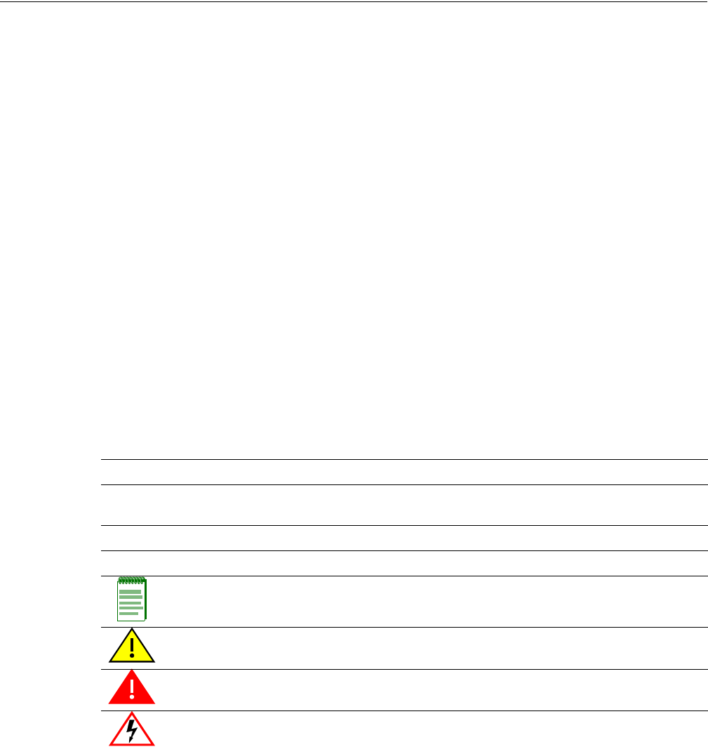
Ad Hoc Wireless LAN (no Access Point)
AnadhocwirelessLANconsistsofagroupofcomputers,eachequippedwithawirelessadapter,
connectedviaradiosignalsasanindependentwirelessLAN.Computersinaspecificadhoc
wirelessLANmustthereforebeconfiguredtothesameradiochannel.AnadhocwirelessLAN
canbeusedforabranchofficeorSOHOoperation.
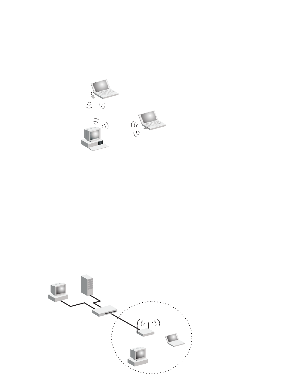
Infrastructure Wireless LAN
TheaccesspointalsoprovidesaccesstoawiredLANforwirelessworkstations.Anintegrated
wired/wirelessLANiscalledanInfrastructureconfiguration.ABasicServiceSet(BSS)consistsof
agroupofwirelessPCusers,andanaccesspointthatisdirectlyconnectedtothewiredLAN.
EachwirelessPCinthisBSScantalktoanycomputerinitswirelessgroupviaaradiolink,or
accessothercomputersornetworkresourcesinthewiredLANinfrastructureviatheaccesspoint.
TheinfrastructureconfigurationnotonlyextendstheaccessibilityofwirelessPCstothewired
LAN,butalsoincreasestheeffectivewirelesstransmissionrangeforwirelessPCsbypassingtheir
signalthroughoneormoreaccesspoints.
Awirelessinfrastructurecanbeusedforaccesstoacentraldatabase,orforconnectionbetween
mobileworkers,asshowninthefollowingfigure.
Ad Hoc Wireless LAN
Notebook with
Wireless USB Adapter
Notebook with
Wireless PC Card
PC with Wireless
PCI Adapter
Server
Switch
Desktop PC
Access Point
Wired LAN Extension
to Wireless Clients
Desktop PC
Notebook PC
Network Topologies
RBT-4102-LIC Access Point Installation Guide 1-3
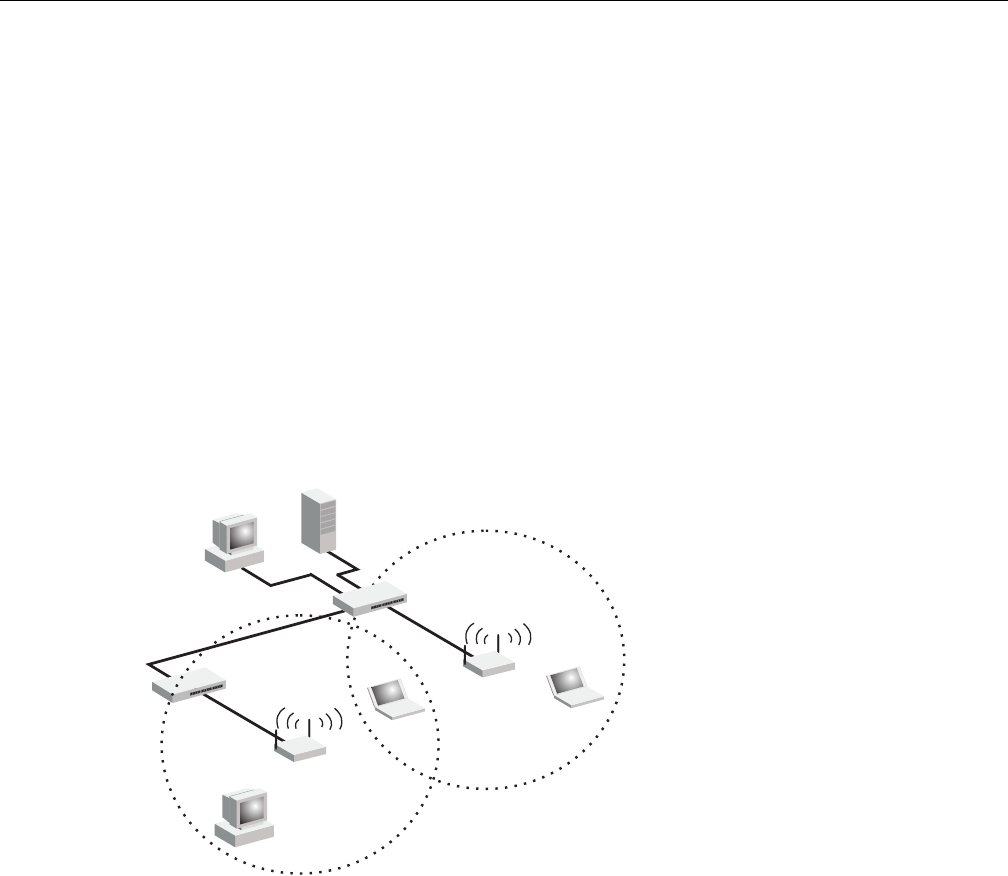
Infrastructure Wireless LAN for Roaming Wireless PCs
TheBasicServiceSet(BSS)definesthecommunicationsdomainforeachaccesspointandits
associatedwirelessclients.TheBSSIDisa48‐bitbinarynumberbasedontheaccesspoint’s
wirelessMACaddress,andissetautomaticallyandtransparentlyasclientsassociatewiththe
accesspoint.TheBSSIDisusedinframessentbetweentheaccesspointanditsclientstoidentify
trafficintheservicearea.
TheBSSIDisonlysetbytheaccesspoint,neverbyitsclients.Theclientsonlyneedtosetthe
ServiceSetIdentifier(SSID)thatidentifiestheservicesetprovidedbyoneormoreaccesspoints.
TheSSIDcanbemanuallyconfiguredbytheclients,canbedetectedinanaccesspoint’sbeacon,or
canbeobtainedbyqueryingfortheidentityofthenearestaccesspoint.Forclientsthatdonot
needtoroam,settheSSIDforthewirelesscardtothatusedbytheaccesspointtowhichyouwant
toconnect.
Awirelessinfrastructurecanalsosupportroamingformobileworkers.Morethanoneaccess
pointcanbeconfiguredtocreateanExtendedServiceSet(ESS).Byplacingtheaccesspointsso
thatacontinuouscoverageareaiscreated,wirelessuserswithinthisESScanroamfreely.All
wirelessnetworkcardsandadaptersandwirelessaccesspointswithinaspecificESSmustbe
configuredwiththesameSSID.
<BSS 2>
<ESS>
<BSS 1>
Server
Switch
Desktop PC
Access Point
Seamless Roaming
Between Access Points
Desktop PC
Notebook PC
Access Point
Notebook PC
Switch
Network Topologies
1-4 Network Configuration
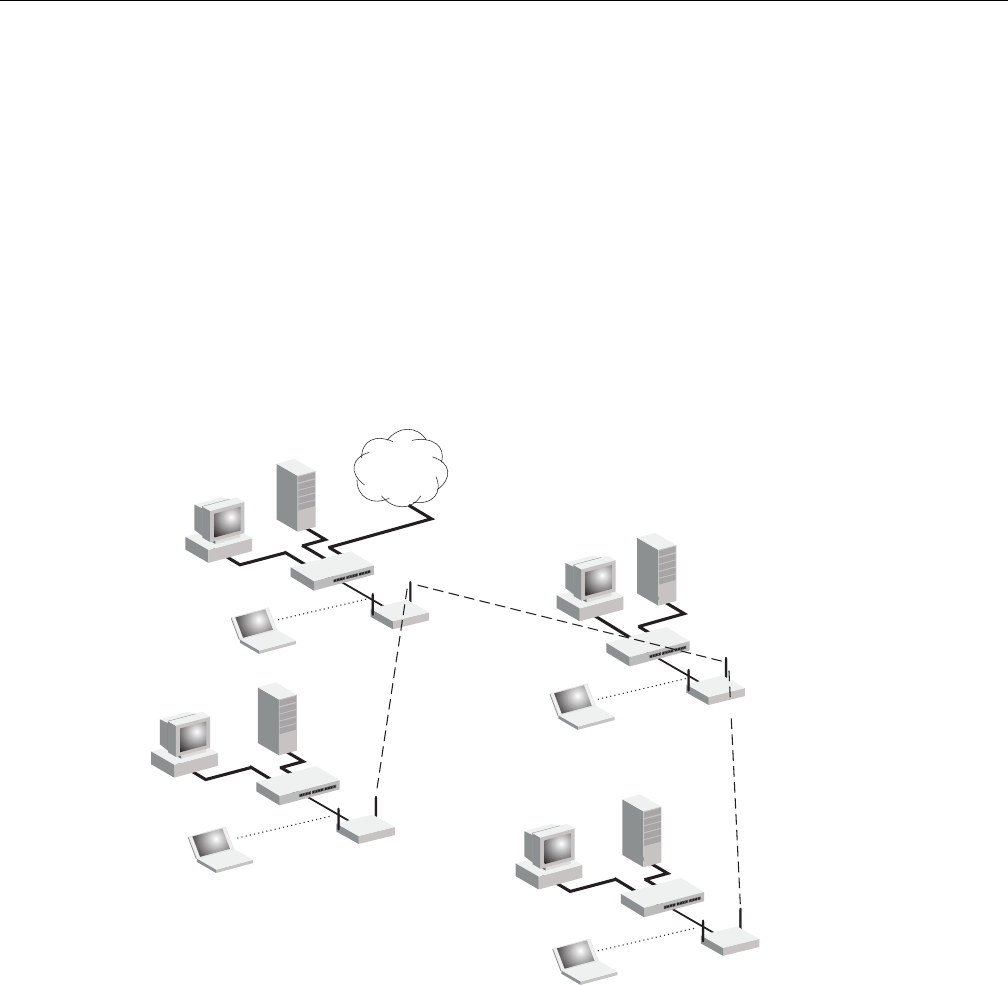
Infrastructure Wireless Bridge
TheIEEE802.11standarddefinesaWirelessDistributionSystem(WDS)forbridgeconnections
betweenBSSareas(accesspoints).TheaccesspointusesWDStoforwardtrafficonlinksbetween
units.
TheaccesspointsupportsWDSbridgelinksoneitherthe5GHz(802.11a)or2.4 GHz(802.11b/g)
bandsandcanbeusedwithvariousexternalantennastoofferflexibledeploymentoptions.
UptosixWDSbridgelinkscanbespecifiedforeachunitinthewirelessbridgenetwork.Oneunit
onlymustbeconfiguredasthe“rootbridge”inthewirelessnetwork.Therootbridgeshouldbe
theunitconnectedtothemaincoreofthewiredLAN.Otherbridgesmustconfigureone“parent”
linktotherootbridgeortoabridgeconnectedtotherootbridge.TheotherfiveavailableWDS
linkscanbespecifiedas“child”linkstootherbridges.Thisformsatiered‐startopologyforthe
wirelessbridgenetwork.
WhenusingWDSonaradioband,onlywirelessbridgeunitscanassociatetoeachother.Wireless
clientscanonlyassociatewiththeaccesspointusingaradiobandsettoaccesspoint.
Wireless Bridge Links
Between Access Points
802.11a Radio
Bridge Link
802.11g Radio
AP Link 802.11a Radio
Bridge Link
802.11g Radio
AP Link
802.11g Radio
AP Link
Root Bridge
Bridge
802.11a Radio
Bridge Link
802.11g Radio
AP Link Bridge
Bridge
Network
Core

RBT-4102-LIC Access Point Installation Guide 2-1
2
Access Point Overview
Features
TheRoamAboutRBT‐4102‐LICisanIEEE802.11a/b/gaccesspointthatprovidestransparent,
wirelesshigh‐speeddatacommunicationsbetweenthewiredLANandfixedormobiledevices
equippedwithan802.11a,802.11b,or802.11gwirelessadapter.
Thissolutionoffersfast,reliablewirelessconnectivitywithconsiderablecostsavingsoverwired
LANs(whichincludelong‐termmaintenanceoverheadforcabling).Using802.11aand802.11g
technology,theseaccesspointscaneasilyreplacea10 MbpsEthernetconnectionorseamlessly
integrateintoa10/100MbpsEthernetLAN.
TheRBT‐4102‐LICsupportsuptoeightVirtualAccessPointsperphysicalradiointerface,thatis
eightonthe802.11aradio,andeightonthe802.11gradio.Thisallowstraffictobeseparatedfor
differentusergroupsusinganaccesspointthatservicesonearea.ForeachVAP,differentsecurity
settings,VLANassignments,andotherparameterscanbeapplied.
EachradiointerfaceontheRBT‐4102‐LICcanoperateinoneofthreemodes:
•AccessPoint–Providingconnectivitytowirelessclientsintheservicearea.
•Bridge(Point‐to‐Point)–Providinglinkstootheraccesspointsin“Bridge”or“RootBridge”
modeconnectingwiredLANsegments.
•RootBridge(Point‐to‐Multipoint)–Providinglinkstootheraccesspointsin“Bridge”mode
connectingwiredLANsegments.Onlyoneunitinthewirelessbridgenetworkcanbesetto
“RootBridge”mode.
Inaddition,theaccesspointoffersfullnetworkmanagementcapabilitiesthroughaneasyto
configurewebinterface,acommandlineinterfaceforinitialconfigurationandtroubleshooting,
andsupportforSimpleNetworkManagementtools.
RadioCharacteristics–TheIEEE802.11a/gstandardusesaradiomodulationtechniqueknownas
OrthogonalFrequencyDivisionMultiplexing(OFDM),andasharedcollisiondomain(CSMA/
CA).Itoperatesatthe5GHzUnlicensedNationalInformationInfrastructure(UNII)bandfor
connectionsto802.11aclients,andat2.4 GHzforconnectionsto802.11gclients.
For information about... Refer to page...
Features 2-1
Package Checklist 2-2
Hardware Description 2-3

Package Checklist
2-2 Access Point Overview
IEEE802.11gincludesbackwardcompatibilitywiththeIEEE802.11bstandard.IEEE802.11balso
operatesat2.4GHz,butusesDirectSequenceSpreadSpectrum(DSSS)andComplementaryCode
Keying(CCK)modulationtechnologytoachieveacommunicationrateofupto11Mbps.
Theaccesspointsupportsa54Mbpshalf‐duplexconnectiontoEthernetnetworksforeachactive
channel(upto108Mbpsinturbomodeonthe802.11ainterface).
Package Checklist
TheRoamAboutpackageincludes:
•OneRoamAboutRBT‐4102‐LIC
•OneRS‐232consolecable
•OneACpoweradapterandpowercord
•Fourrubberfeet
•Threewall‐mountingscrews
•Bezel
• Mountingbracket
•ThisInstallationGuide
• DocumentationCD(includestheInstallationGuideandManagementGuide)
Informyourdealerifthereareanyincorrect,missingordamagedparts.Ifpossible,retainthe
carton,includingtheoriginalpackingmaterials.Usethemagaintorepacktheproductincase
thereisaneedtoreturnit.
Caution: The Bezel should not be used in a plenum area.
Hardware Description
RBT-4102-LIC Access Point Installation Guide 2-3
Hardware Description
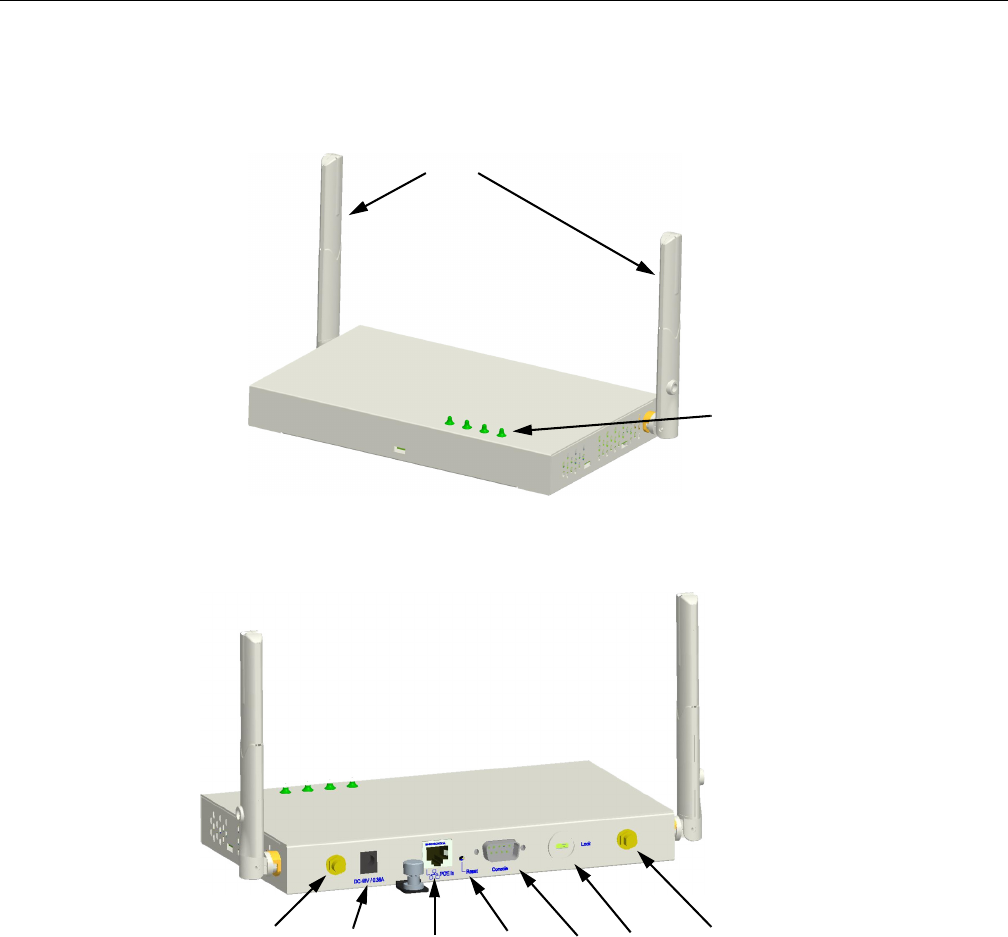
Top Panel
Rear Panel
Component Description
Antennas
Theaccesspointincludesintegrateddiversityantennasforwirelesscommunications.Adiversity
antennasystemusestwoidenticalantennastoreceiveandtransmitsignals,helpingtoavoid
multipathfadingeffects.Whenreceiving,theaccesspointchecksbothantennasandselectsthe
onewiththestrongestsignal.Whentransmitting,itwillcontinuetousetheantennapreviously
selectedforreceiving.Theaccesspointnevertransmitsfrombothantennasatthesametime.
LED
Indicators
Antennas
Security
Slot
Console
Port
RJ-45 Port,
PoE
Connector
Reset
Button External Antenna
Connector
(802.11b/g Radio)
DC Power
Supply
External Antenna
Connector
(802.11a) Radio
Hardware Description
2-4 Access Point Overview
Theantennastransmittheoutgoingsignalasatoroidalsphere(doughnutshaped),withthe
coverageextendingmostinadirectionperpendiculartotheantenna.Theantennashouldbe
adjustedtoananglethatprovidestheappropiatecoveragefortheservicearea.Forfurther
information,see“PositiontheAntennas”onpage3‐4.
External Antenna Connectors
Theaccesspointsupportsexternalantennaconnectionsforboththe2.4GHzand5GHzradios.
Theseantennasofferavarietyofoptionsforextendingtheradiorangeandshapingthecoverge
area.Foralistofexternalantennas,theirmodeltypeandgainreferto“ExternalAntennas”on
page C‐6.
Forinformationontheexternalantennasavailable,refertothefollowingdocumentonthe
EnterasysWebsite:
http://www.enterasys.com/support/manuals/n‐s.html#R
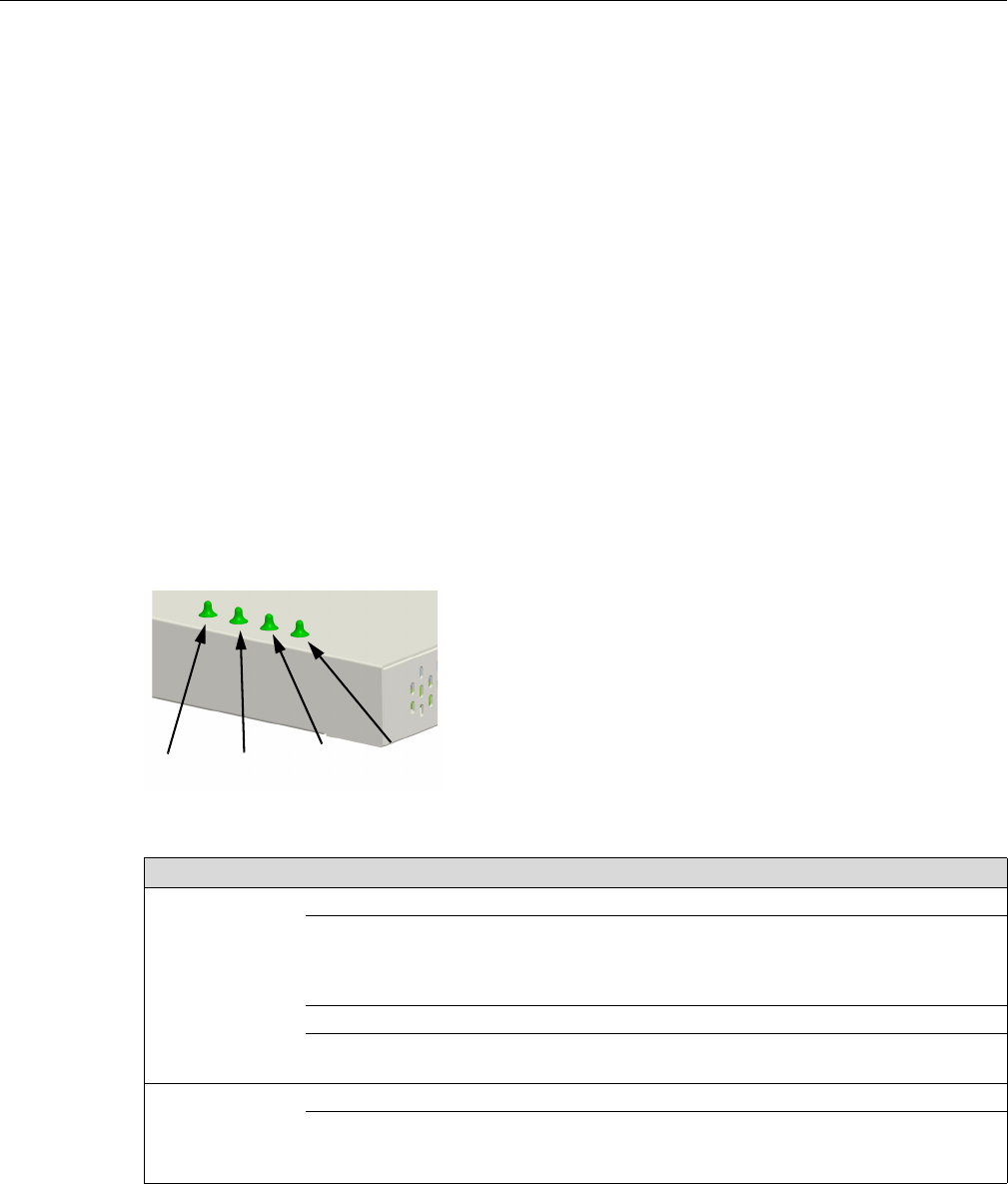
LED Indicators
TheaccesspointincludesfourstatusLEDindicators,asshowninFigure 2‐1,anddescribedin
Table 2‐1.
Figure 2-1 LED Indicators
Table 2-1 LED Status Descriptions
LED Status Description
Power On Green Indicates that the system is working normally.
Flashing Green Indicates:
• running a self-test.
• loading software program.
On Amber Indicates a CPU or system failure.
Flashing Amber
(Prolonged)
Indicates system errors.
Link On Green Indicates a valid 10/100 Mbps Ethernet cable link.
Flashing Green Indicates that the access point is transmitting or receiving data
on a 10/100 Mbps Ethernet LAN. Flashing rate is proportional
to your network activity.
Power 802.11a
Wireless
Link/Activity
Ethernet
Link/Activity
802.11b/g
Wireless
Link/Activity

Hardware Description
RBT-4102-LIC Access Point Installation Guide 2-5
Security Slot
TheaccesspointincludesaKensingtonsecurityslotontherearpanel.Youcanprevent
unauthorizedremovaloftheaccesspointbywrappingtheKensingtonsecuritycable(not
provided)aroundanunmovableobject,insertingthelockintotheslot,andturningthekey.
Console Port
Thisportisusedtoconnectaconsoledevicetotheaccesspointthroughaserialcable.This
connectionisdescribedunder“ConsolePortPinAssignments”onpage B‐4.Theconsoledevice
canbeaPCorworkstationrunningaVT‐100terminalemulator,oraVT‐100terminal.
Ethernet Port
Theaccesspointhasone10BASE‐T/100BASE‐TXRJ‐45portthatcanbeattacheddirectlyto
10BASE‐T/100BASE‐TXLANsegments.ThesesegmentsmustconformtotheIEEE802.3or802.3u
specifications.
ThisportsupportsautomaticMDI/MDI‐Xoperation,soyoucanusestraight‐throughcablesforall
networkconnectionstoPCs,switches,orhubs.
TheaccesspointappearsasanEthernetnodeandperformsabridgingfunctionbymoving
packetsfromthewiredLANtoremoteworkstationsonthewirelessinfrastructure.
Reset Button
Thisbuttonisusedtoresettheaccesspointorrestorethefactorydefaultconfiguration.Ifyouhold
downthebuttonforlessthan5seconds,theaccesspointwillperformahardwarereset.Ifyou
holddownthebuttonfor5secondsormore,anyconfigurationchangesyoumayhavemadeare
removed,andthefactorydefaultconfigurationisrestoredtotheaccesspoint.
802.11a On Green Indicates the 802.11a radio is enabled.
Flashing Green Indicates that the access point is transmitting or receiving data
through wireless links. Flashing rate is proportional to network
activity.
Off Indicates the 802.11a radio is disabled.
802.11b/g On Green Indicates the 802.11b/g radio is enabled.
Flashing Green Indicates that the access point is transmitting or receiving data
through wireless links. Flashing rate is proportional to network
activity.
Off Indicates the 802.11b/g radio is disabled.
Table 2-1 LED Status Descriptions (continued)
LED Status Description
Note: The RJ-45 port also supports Power over Ethernet (PoE) based on the IEEE 802.3af
standard. Refer to the description for the “Power Connector” for information on supplying power to
the access point’s network port from a network device, such as a switch, that provides Power over
Ethernet (PoE).

Hardware Description
2-6 Access Point Overview
Power Connector
Theaccesspointdoesnothaveapowerswitch.ItispoweredonwhenconnectedtotheACpower
adapter,andthepoweradapterisconnectedtoapowersource.Thepoweradapterautomatically
adjuststoanyvoltagebetween100~240voltsat50or60Hz.Novoltagerangesettingsare
required.
TheaccesspointmayalsoreceivePoweroverEthernet(PoE)fromaswitchorothernetwork
devicethatsuppliespoweroverthenetworkcablebasedontheIEEE802.3afstandard.
Notes:
• The access point supports both endspan and midspan PoE.
• If the access point is connected to a PoE source device and also connected to a local power
source through the AC power adapter, AC power will be disabled.

RBT-4102-LIC Access Point Installation Guide 3-1
3
Installing and Connecting Your Access Point
Installation Requirements and Recommendations
SelectaSite–Chooseaproperplacefortheaccesspoint.Ingeneral,thebestlocationisatthe
centerofyourwirelesscoveragearea,withinlineofsightofallwirelessdevices.Trytoplacethe
accesspointinapositionthatcanbestcoveritsBasicServiceSet(referto“InfrastructureWireless
LAN”onpage 1‐2).Foroptimumperformance,considerthesepoints:
• Mounttheaccesspointashighaspossibleaboveanyobstructionsinthecoveragearea.
•Avoidmountingnexttoornearbuildingsupportcolumnsorotherobstructionsthatmay
causereducedsignalornullzonesinpartsofthecoveragearea.
• Mountawayfromanysignalabsorbingorreflectingstructures(suchasthosecontaining
metal).
For information about... Refer to page...
Installation Requirements and Recommendations 3-1
Installing the Access Point 3-2
Installing the Access Point
3-2 Installing and Connecting Your Access Point
Installing the Access Point
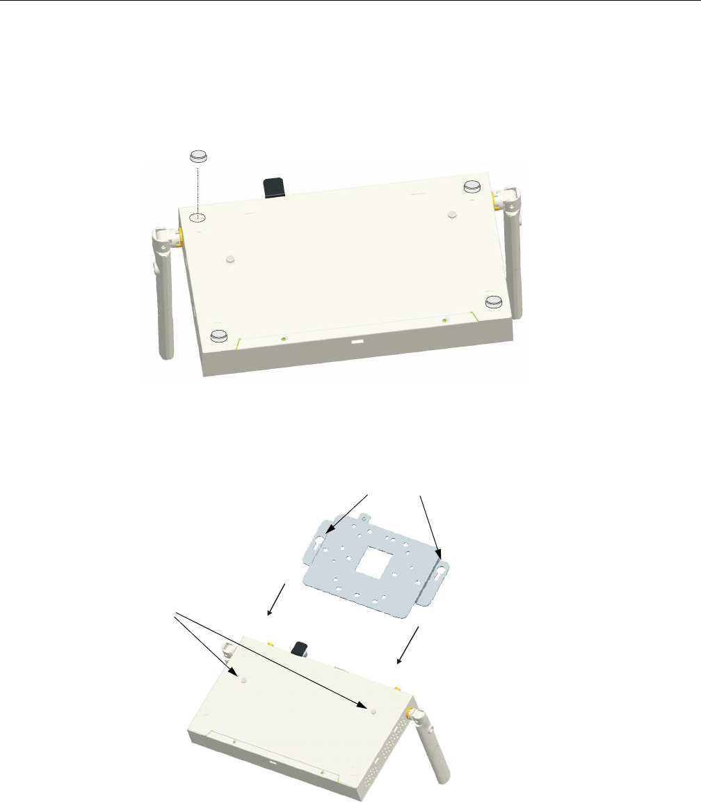
1. MounttheAccessPoint–Theaccesspointcanbemountedonanyhorizontalsurfaceora
wall.
•MountingonaHorizontalSurface–Tokeeptheaccesspointfromslidingonthesurface,
attachthefourrubberfeetprovidedintheaccessorykittothemarkedcirclesonthebottom
oftheaccesspoint.
•MountingonaWall–Tomountonawallorceilingyoumustfirstattachthemounting
brackettothebaseoftheaccesspoint.Alignthetwomountingslotsonthebracketwiththe
raisedattachingslatsandscrewtheunitintoplacefirmly.
Theaccesspointshouldbemountedonlytoawallorwoodsurfacethatisatleast1/2‐inch
thickplywoodoritsequivalent.Tomounttheaccesspointonawall,alwaysuseitswall‐
mountingbracket.TheaccesspointmustbemountedwiththeRJ‐45cableconnectororiented
upwardstoensureproperoperation.
Mounting Slots
Bottom of Access Point
Attaching Slats
Installing the Access Point
RBT-4102-LIC Access Point Installation Guide 3-3
2. Usingthemountingbracket,markthepositionofthefourscrewholesonthewall.For
concreteorbrickwalls,youwillneedtodrillholesandinsertwallplugsforthescrews.
3. Positionthemountingbracketoverthewallscrewholes,theninserttheincludedscrewsand
tightenthemdowntosecurethebracketfirmlytothewall.
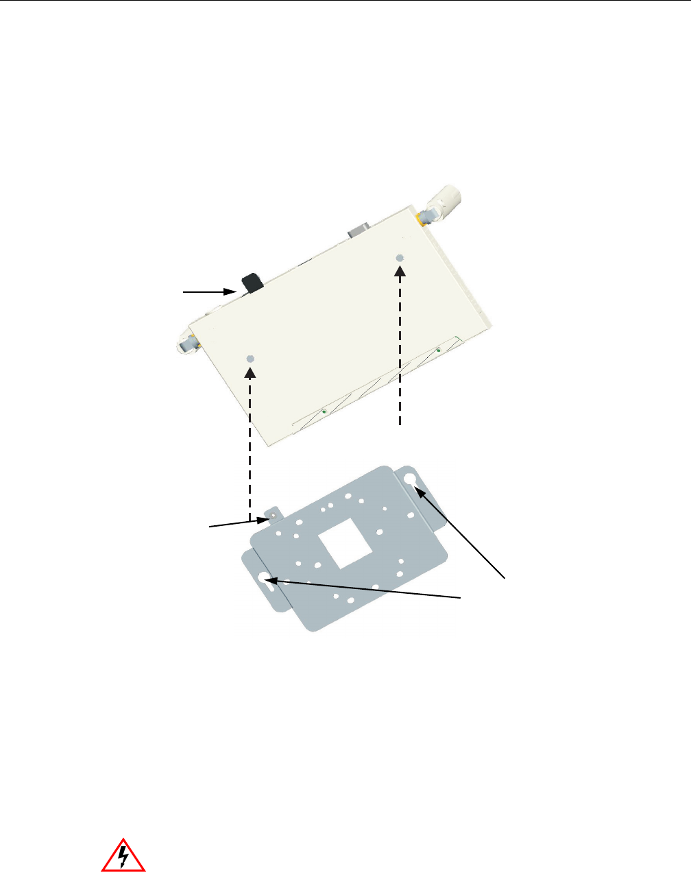
4. Attachtheaccesspointtothemountingbracket.Lineupthetwomountingpointsonthe
bracketwiththetwomountingslotsonthebottomoftheaccesspoint(seethefollowing
figure).Placethemountingpointsofthebracketintothemountingslotsofthebracket,slideit
intopositionsothatthebracketfasteningscrewontheaccesspointlinesupwiththetabon
thebracket.Thenscrewdownthefasteningscrewtosecuretheaccesspointtothebracket.
5. LocktheAccessPointinPlace–Topreventunauthorizedremovaloftheaccesspoint,you
canuseaKensingtonSlimMicroSaversecuritycable(notincluded)toattachtheaccesspoint
toafixedobject.
6. ConnectthePowerCord–Connectthepoweradaptertotheaccesspoint,andthepowercord
toanACpoweroutlet.Otherwise,theaccesspointcanderiveitsoperatingpowerdirectly
fromtheRJ‐45portwhenconnectedtoadevicethatprovidesIEEE802.3afcompliantPower
overEthernet(PoE).
Warning: Use ONLY the power adapter supplied with this access point. Otherwise, the
product may be damaged.
Mounting
Points
Mounting
Slots
Bracket
Fastening
Screw
Align this tab with
the Fastening
Screw

Installing the Access Point
3-4 Installing and Connecting Your Access Point
7. ObservetheSelfTest–Whenyoupowerontheaccesspoint,verifythatthePowerindicator
stopsflashingandremainson,andthattheotherindicatorsstartfunctioningasdescribedin
“LEDIndicators”onpage 2‐4.
IfthePWRLEDdoesnotstopflashing,theselftesthasnotcompletedcorrectly.Referto
Appendix A,DiagnosingAccessPointIndicators.
8. ConnecttheEthernetCable–Theaccesspointcanbewiredtoa10/100MbpsEthernet
throughanetworkdevicesuchasahuboraswitch.ConnectyournetworktotheRJ‐45port
onthebackpanelwithcategory3,or4UTPEthernetcable.Whentheaccesspointandthe
connecteddevicearepoweredon,theEthernetLinkLEDshouldlightindicatingavalid
networkconnection.
9. PositiontheAntennas–Eachantennaemitsaradiationpatternthatistoroidal(doughnut
shaped),withthecoverageextendingmostinthedirectionperpendiculartotheantenna.
Therefore,theantennasshouldbeorientedsothattheradiocoveragepatternfillsthe
intendedhorizontalspace.Also,thediversityantennasshouldbothbepositionedalongthe
sameaxes,providingthesamecoveragearea.Forexample,iftheaccesspointismountedona
horizontalsurface,bothantennasshouldbepositionedpointingverticallyuptoprovide
optimumcoverage.
10. ConnecttheConsolePort–Connecttheconsolecable(includedwithRBT‐4102‐LIC)tothe
RS‐232consoleportforaccessingthecommand‐lineinterface.Youcanmanagetheaccess
pointusingtheconsoleport,thewebinterface,orSNMPmanagementsoftware,suchas
EnterasysNetSightorHP’sOpenView.
Note: If the access point is connected to both a PoE source device and an AC power
source, AC will be disabled.
Note: The RJ-45 port on the access point supports automatic MDI/MDI-X operation, so you
can use straight-through cables for all network connections to PCs, switches, or hubs.

RBT-4102-LIC Access Point Installation Guide 4-1
4
Initial Configuration
Overview
YoucanmanagetheRoamAboutRBT‐4102‐LICWirelessAccessPointusing:
•TheCommandLineInterface(CLI)accessedthroughadirectconnectiontotheconsoleport
RefertoRoamAboutRBT‐4102WirelessAccessPointConfigurationGuidetoviewalistofallthe
CLIcommands,andhowtousethem.
•Thewebinterfaceaccessedthroughawebbrowser(InternetExplorerV5.0orabove,or
NetscapeNavigatorV6.2orabove).
•AnSNMPmanager,suchasEnterasysNetworksNetSightmanagementapplications.
Using the CLI
Required Connections
TheaccesspointprovidesanRS‐232serialportthatenablesaconnectiontoaPCorterminalfor
monitoringandconfiguration.AttachaVT100‐compatibleterminal,oraPCrunningaterminal
emulationprogramtotheaccesspoint.Youcanusetheconsolecableprovidedwiththispackage,
oruseacablethatcomplieswiththewiringassignments.
Toconnecttotheconsoleport,performthefollowingsteps:
1. Connecttheconsolecabletotheserialportonaterminal,oraPCrunningterminalemulation
software,andtightenthecaptiveretainingscrewsontheDB‐9connector.
2. ConnecttheotherendofthecabletotheRS‐232serialportontheaccesspoint.
3. Makesuretheterminalemulationsoftwareissetasfollows:
•Selecttheappropriateserialport(COMport1or2).
•Setthedatarateto9600baud.
•Setthedataformatto8databits,1stopbit,andnoparity.
•Setflowcontroltonone.
Note: You must click on the Apply button at the bottom of each Web interface page for the
configuration changes on that page to take effect.
Using the CLI
4-2 Initial Configuration
•SettheemulationmodetoVT100.
•WhenusingHyperTerminal,selectTerminalkeys,notWindowskeys.
4. Onceyouhavesetuptheterminalcorrectly,presstheEnterkeytoinitiatetheconsole
connection.Theconsoleloginscreenisdisplayed.
Logging In
TousetheCLItominimallyconfiguretheaccesspoint,followthesesteps:
1. Enteradminfortheusername,andpasswordforthepasswordtologin.
TheAccessPoint4102CLIpromptappears.
2. IfyouraccesspointusesaDHCPassignedIPaddress,gotoStep 3tochangethedefault
usernameandpassword.
Otherwise,disableDHCPforthisaccesspointasfollows:
a. Typeconfiguretoenterconfigurationmode.
b. TypeinterfaceethernettoaccesstheEthernetinterfaceconfigurationmode.
Note: When using HyperTerminal with Microsoft® Windows® 2000, make sure that you have
Windows 2000 Service Pack 2 or later installed. Windows 2000 Service Pack 2 fixes the problem of
arrow keys not functioning in HyperTerminal’s VT100 emulation. Go to www.microsoft.com for
information on Windows 2000 service packs.
Username: admin
Password:********
RoamAbout 4102#
Note: The access point requests an IP address from a Dynamic Host Configuration Protocol
(DHCP) server by default. If a DHCP server does not respond, then the access point uses the
default address, 192.168.1.1, which may not be compatible with your network. To assign an IP
address, you must use the CLI. Go to Step 2.
RoamAbout 4102#configure
Enter configuration commands, one per line. End with CTRL/Z
RoamAbout 4102(config)#interface ethernet
Enter Ethernet configuration commands, one per line.
RoamAbout 4102(if-ethernet)#

Using the CLI
RBT-4102-LIC Access Point Installation Guide 4-3
c. DisableDHCP.Typenoipdhcp.
d. SettheIPAddress.Typeipaddressip‐addressnetmaskgateway,whereip‐addressisthe
accesspoint’sIPaddress,netmaskisthenetworkmaskforthenetwork,andgatewayis
thedefaultgatewayrouter.CheckwithyoursystemadministratortoobtainanIPaddress
thatiscompatiblewithyournetwork.
Afterconfiguringtheaccesspoint’sIPparameters,youcanaccessthemanagement
interfacefromanywherewithintheattachednetwork.Thecommandlineinterfacecan
alsobeaccessedusingTelnetfromanycomputerattachedtothenetwork.
3. Changethedefaultusernameandpassword:typeusernameandspecifyauniqueusername;
typepasswordandspecifyauniquepassword.
4. EnableManagementVLAN.
a. Typemanagement‐vlanidandspecifyamanagementvlanid.
b. Typemanagement‐vlanenable,andresettheaccesspoint.
5. RefertotheRoamAboutRBT‐4102WirelessAccessPointConfigurationGuideforadvanced
configuration.
RoamAbout 4102(if-ethernet)#no ip dhcp
DHCP client state has changed. Please reset AP for change to take effect.
RoamAbout 4102(if-ethernet)#exit
RoamAbout 4102#reset board
Reboot system now? <y/n>: y
Username: admin
Password:********
RoamAbout 4102#configure
Enter configuration commands, one per line. End with CTRL/Z
RoamAbout 4102(config)#interface ethernet
Enter Ethernet configuration commands, one per line.
RoamAbout 4102(if-ethernet)#
RoamAbout 4102(if-ethernet)#ip address ip-address netmask gateway
RoamAbout 4102(if-ethernet)#end
RoamAbout 4102(config)#
RoamAbout 4102(config)#username KateJB
RoamAbout 4102(config)#password ******
Confirm new password: ******
RoamAbout 4102(config)#
Note: Before enabling the VLAN feature on the access point, you must set up the network switch
port to support tagged VLAN packets from the access point. The switch port must also be
configured to accept the access point’s management VLAN ID and native VLAN IDs. Otherwise,
connectivity to the access point will be lost when you enable the VLAN feature.
RoamAbout 4102(config)#management-vlanid 10
RoamAbout 4102(config)#management-vlan enable
Reboot system now? <y/n>:y
Username: admin
Password:********
Using Web Management
4-4 Initial Configuration
Using Web Management
TousetheWebinterfacetominimallyconfiguretheaccesspoint,followthesesteps:
1. OpenaWebbrowserandentertheaccesspoint’sIPaddressintheaddressfield:
•IfyouraccesspointusesaDHCPassignedIPaddress,makesuretheaccesspointis
connectedtoyournetwork,andentertheDHCPassignedIPaddressinyourbrowser’s
addressfield.UseyourDHCPserverorotherutilitytodeterminetheaccesspoint’sIP
address.
•IfyouraccesspointusesastaticIPaddress,connectasystemtotheaccesspoint’sEthernet
portandenterthedefaultIPaddress:http://192.168.1.1/inyourbrowser’saddressfield.
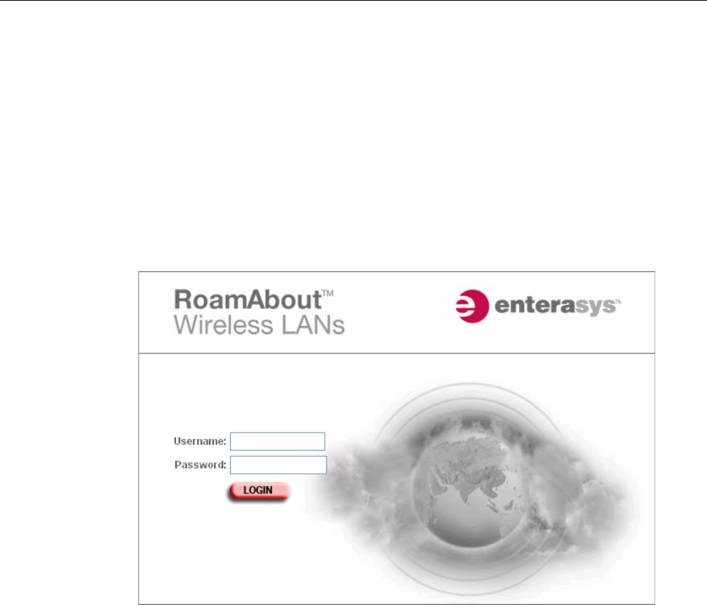
Theaccesspoint’sLoginwindowappears.
2. EntertheusernameadminandthepasswordpasswordandclickLOGIN.
.
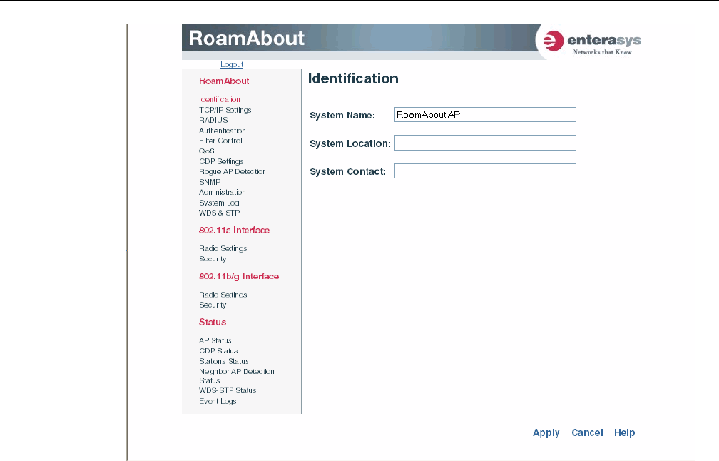
TheIdentificationpageappears.
Using Web Management
RBT-4102-LIC Access Point Installation Guide 4-5
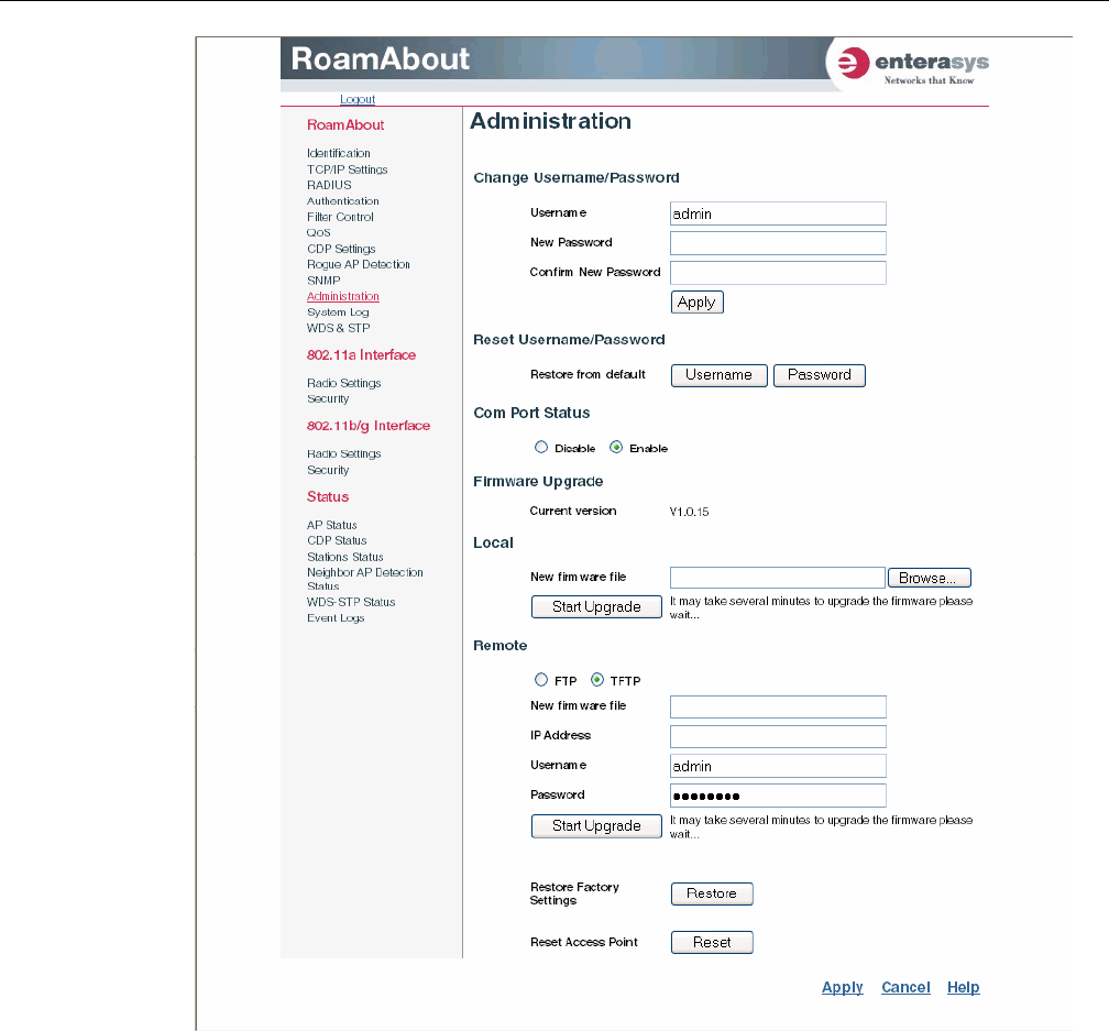
c. ClickAdministrationfromthemenuontheleft‐handsideofthepage.
TheAdministrationpageappears.
Using Web Management
4-6 Initial Configuration
d. ClickReset,atthebottomofthepage.
Theaccesspointpromptsyoutoconfirmthatyouwanttorebootthesystem.
e. ClickOK.
TheaccesspointrebootsandtheLoginwindowappears.
f. EntertheusernameadminandthepasswordpasswordandclickLOGIN.
Using Web Management
RBT-4102-LIC Access Point Installation Guide 4-7
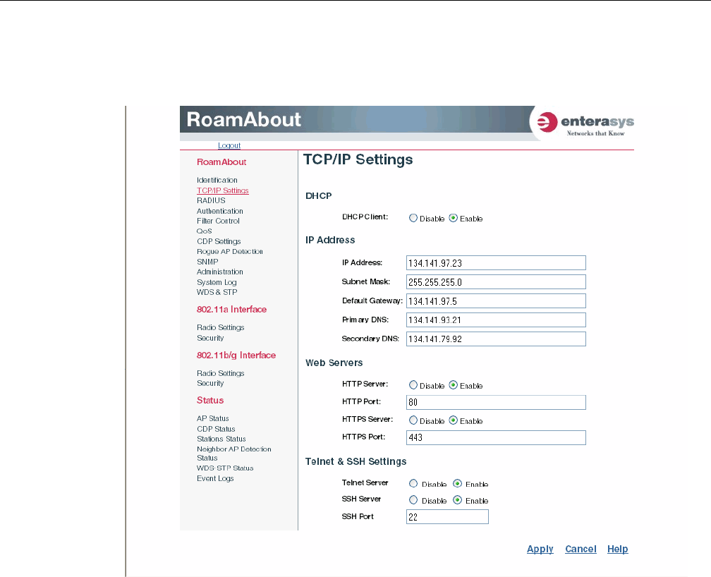
3. TosetastaticIPaddress:
a. ClickTCP/IPSettingsfromthemenuonthelefthandsideofthepage.
TheTCP/IPSettingspageappears.
b. ClicktheDHCPClient:Disableradiobutton.
AnIPAddresssectionappearsonthepage.
c. SpecifytheIPAddress,SubnetMask,DefaultGateway,andPrimaryandSecondary
DNS.
d. ClickApplyatthebottomofthepage.
e. TypetheIPaddressthatyouspecifiedfortheaccesspointinyourbrowser’saddressfield.
Forexample,enterhttp://10.2.101.22/.
TheLoginwindowappears.
f. EntertheusernameadminandthepasswordpasswordandclickLOGIN.
g. ClickAdministrationfromthemenuontheleftofthepage.
TheAdministrationpageappears.
h. ClickReset,atthebottomofthepage.
Theaccesspointpromptsyoutoconfirmthatyouwanttorebootthesystem.

Using Web Management
4-8 Initial Configuration
i. ClickOK.
TheaccesspointrebootsandtheLoginwindowappears.
j. EntertheusernameadminandthepasswordpasswordandclickLOGIN.
4. Setusernameandpassword.
a. ClickAdministrationfromthemenu.
TheAdministrationpageappears.
b. SpecifyanewusernameintheUsernamefield.
c. SpecifyanewpasswordinthePasswordfield.
d. SpecifythenewpasswordagainintheConfirmPasswordfield.
e. ClickApplyatthebottomofthepage.
TheaccesspointdisplaysaSettingsSavedmessage.
f. ClickOK.
TheAdministrationpageappears.
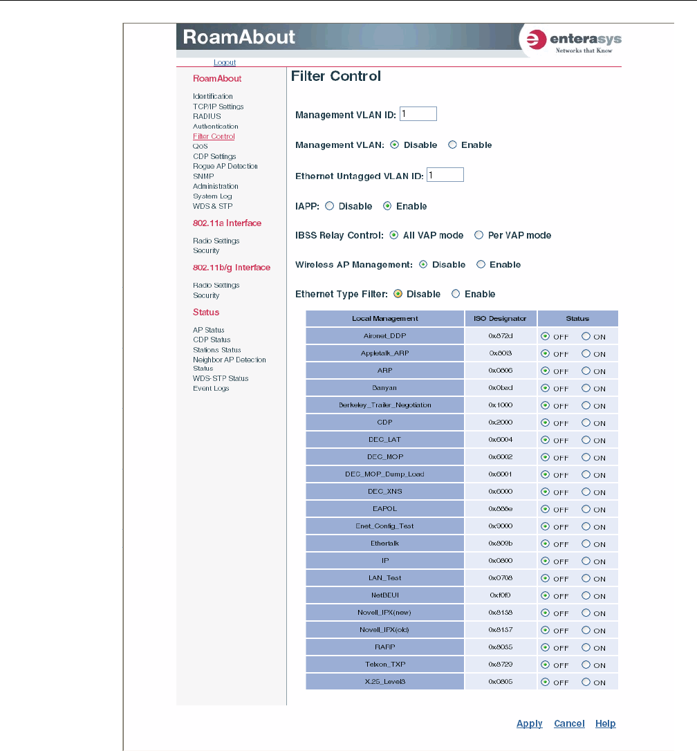
5. SetmanagementVLAN:
a. ClickFilterControlfromthemenu.
TheFilterControlpageappears.
Using Web Management
RBT-4102-LIC Access Point Installation Guide 4-9
b. ClicktheManagementVLANID:fieldandentertheVLANIDfromwhichyouwill
managetheAP.
c. ClicktheManagementVLAN:Enableradiobutton.

Using Web Management
4-10 Initial Configuration
d. ClickApplyatthebottomofthepage.
TheaccesspointdisplaysadialogboxindicatingthattheVLANstatushaschangedand
willtakeeffectafterthenextreboot.Thedialogboxpromptsyoutochoosewhetherto
rebootnoworlater.
e. ClickOKtorebootnow.
TheaccesspointrebootsandtheLoginwindowappears.
f. Entertheusernameandthepasswordthatyouspecifiedforthisaccesspointandclick
LOGIN.
6. RefertotheRoamAboutRBT‐4102WirelessAccessPointConfigurationGuideforadvanced
configuration.

RBT-4102-LIC Access Point Installation Guide A-1
A
Diagnosing Access Point Indicators
Troubleshooting Chart
Symptom Action
Power LED is Off • AC power adapter may be disconnected. Check connections between
the access point, the power adapter, and the wall outlet.
• PoE power to the access point may be disabled at the connected
switch port. Check the switch configuration to be sure that PoE power
is enabled for the switch and specified port. Also check that the switch
has not exceeded its power budget and turned off the port power.
Power LED is Amber The access point has detected a system error. Reboot the access point
to try and clear the condition.
If the condition does not clear, contact your local dealer for assistance.
Ethernet/Link LED is Off • Verify that the access point and attached device are powered on.
• Be sure the cable is plugged into both the access point and
corresponding device.
• Verify that the proper cable type is used and its length does not exceed
specified limits.
• Check the cable connections for possible defects. Replace the
defective cable if necessary.
Note: For troubleshooting wireless connectivity problems, refer to the RoamAbout Wireless Access Point RBT-4102
Configuration Guide.

A-2 Diagnosing Access Point Indicators
RBT-4102-LIC Access Point Installation Guide B-1
B
Cables and Pin-outs
Twisted-Pair Cable Assignments
For10/100BASE‐TXconnections,atwisted‐paircablemusthavetwopairsofwires.Eachwirepair
isidentifiedbytwodifferentcolors.Forexample,onewiremightbegreenandtheother,green
withwhitestripes.Also,anRJ‐45connectormustbeattachedtobothendsofthecable.
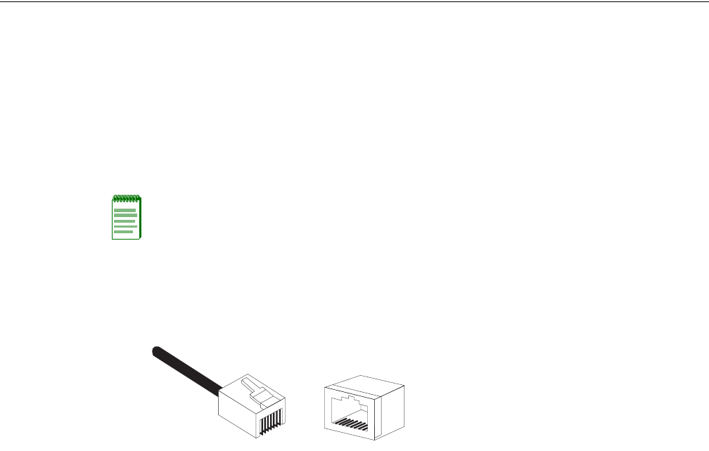
ThefollowingfigureillustrateshowthepinsontheRJ‐45connectorarenumbered.Besuretohold
theconnectorsinthesameorientationwhenattachingthewirestothepins.
Notes:
• Each wire pair must be attached to the RJ-45 connectors in a specific orientation. (Refer to
“Straight-Through Wiring” on page B-3 and “Crossover Wiring” on page B-4 for an explanation.)
• DO NOT plug a phone jack connector into the RJ-45 port. Use only twisted-pair cables with RJ-45
connectors that conform with FCC standards.
1
881

B-2 Cables and Pin-outs
10/100BASE-TX Pin Assignments
Useunshieldedtwisted‐pair(UTP)orshieldedtwisted‐pair(STP)cableforRJ‐45connections:
100‐ohmCategory3orbettercablefor10Mbpsconnections.Alsobesure
thatthelengthofany
twisted‐pairconnectiondoesnotexceed100meters(328feet).
TheRJ‐45portontheaccesspointsupportsautomaticMDI/MDI‐Xoperation,soyoucanuse
straight‐throughorcrossovercablesforallnetworkconnectionstoPCs,switches,orhubs.In
straight‐throughcable,pins1,2,3,and6,atoneendofthecable,areconnectedstraightthroughto
pins1,2,3,and6attheotherendofthecable.
Pin MDI Signal Name MDI-X Signal Name
1 Receive Data plus (RD+)
and GND (Positive Vport)
Transmit Data plus (TD+)
and -48V feeding power (Negative Vport)
2 Receive Data minus (RD-)
and GND (Positive Vport)
Transmit Data minus (TD-)
and -48V feeding power (Negative Vport)
3 Transmit Data minus (TD+)
and -48V feeding power (Negative Vport)
Receive Data plus (RD+)
and GND (Positive Vport)
4 GND (Positive Vport) -48V feeding power (Negative Vport)
5 GND (Positive Vport) -48V feeding power (Negative Vport)
6 Transmit Data minus (TD-)
and -48V feeding power (Negative Vport)
Receive Data minus (RD-)
and GND (Positive Vport)
7 -48V feeding power (Negative Vport) GND (Positive Vport)
8 -48V feeding power (Negative Vport) GND (Positive Vport)
Note: The “+” and “-” signs represent the polarity of the wires that make up each wire pair.

RBT-4102-LIC Access Point Installation Guide B-3
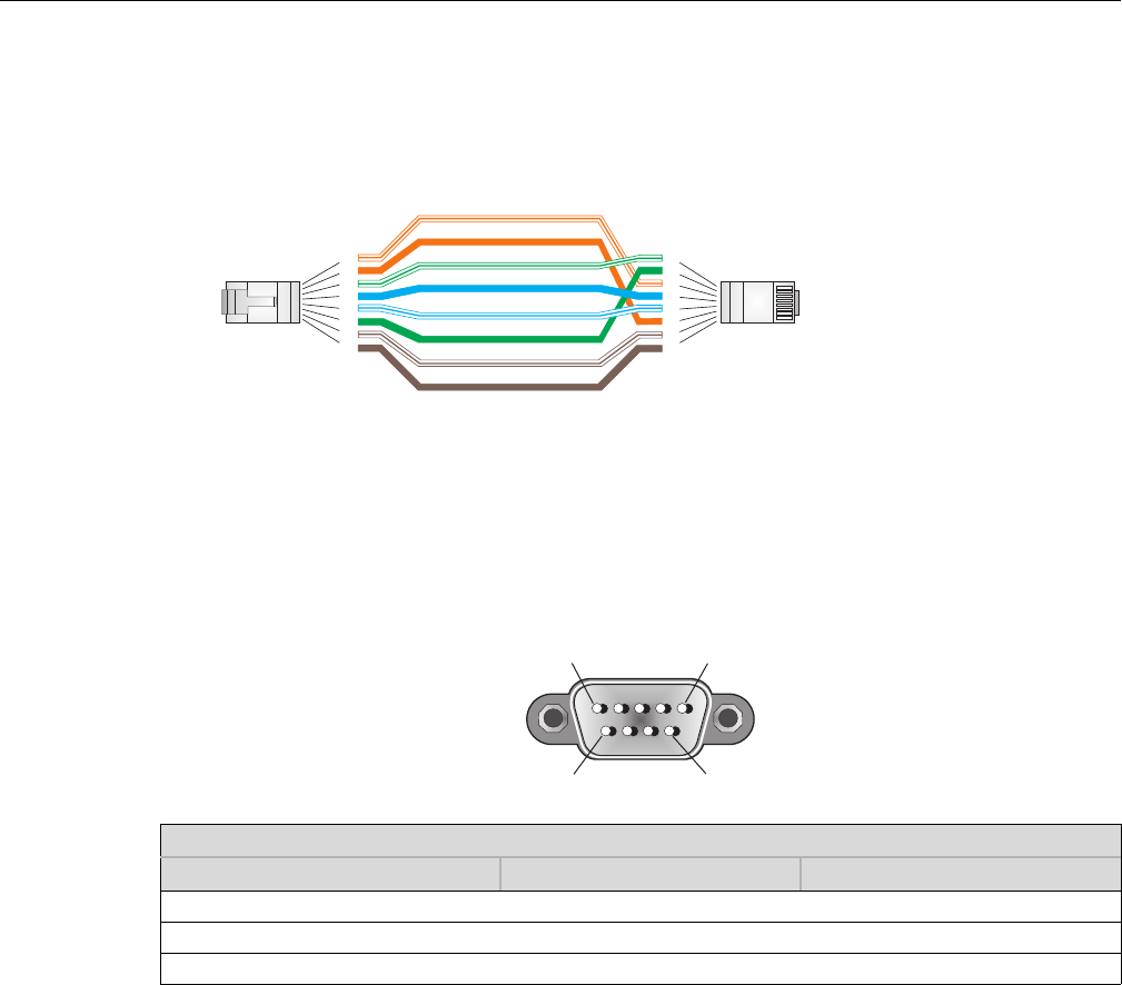
Straight-Through Wiring
Ifthetwisted‐paircableistojointwoportsandonlyoneoftheportshasaninternalcrossover
(MDI‐X),thetwopairsofwiresmustbestraight‐through.
White/Orange Stripe
Orange
White/Green Stripe
Green
1
2
3
4
5
6
7
8
1
2
3
4
5
6
7
8
EIA/TIA 568B RJ-45 Wiring Standard
10/100BASE-TX Straight-through Cable
End A End B
Blue
White/Blue Stripe
Brown
White/Brown Stripe
B-4 Cables and Pin-outs
Crossover Wiring
Ifthetwisted‐paircableistojointwoportsandeitherbothportsarelabeledwithan“X”(MDI‐X)
orneitherportislabeledwithan“X”(MDI),acrossovermustbeimplementedinthewiring.
Console Port Pin Assignments
TheDB‐9consoleportonthefrontpaneloftheaccesspointisusedtoconnecttotheaccesspoint
forout‐of‐bandconsoleconfiguration.Thecommand‐lineconfigurationprogramcanbeaccessed
fromaterminal,oraPCrunningaterminalemulationprogram.Thepinassignmentsandcable
wiringusedtoconnecttotheconsoleportareprovidedinthefollowingtable.
White/Orange Stripe
Orange
White/Green Stripe
1
2
3
4
5
6
7
8
1
2
3
4
5
6
7
8
EIA/TIA 568B RJ-45 Wiring Standard
10/100BASE-TX Crossover Cable
End A End B
Green
Blue
White/Blue Stripe
Brown
White/Brown Stripe
10/100BASE-TX MDI and MDI-X Port Pinouts
Switch’s 9-Pin Serial Port Null Modem PC’s 9-Pin DTE Port
2 RXD <---------RXD ------------ 3 TxD
3 TXD -----------TXD ----------> 2 RxD
5 SGND -----------SGND ---------- 5 SGND
Note: The left hand column pin assignments are for the male DB-9 connector on the access point. Pin 3 (TXD or “transmit
data”) must emerge on the management console’s end of the connection as RXD (“receive data”).
15
69

RBT-4102-LIC Access Point Installation Guide C-1
C
Specifications
Maximum Channels
802.11a:
RBT‐4102‐LIC
US&Canada:13(normalmode),5(turbomode),3(in4.9GHzlicensedmode)
802.11b/g:
RBT‐4102‐LIC
FCC/IC:1‐11
Data Rate
802.11a:
NormalMode:6,9,12,18,24,36,48,54Mbpsperchannel
TurboMode:12,18,24,36,48,54,96,108Mbpsperchannel
802.11g:6,9,11,12,18,24,36,48,54Mbpsperchannel
802.11b:1,2,5.5,11Mbpsperchannel
Modulation Type
802.11a:BPSK,QPSK,16‐QAM,64‐QAM
802.11g:CCK,BPSK,QPSK,OFDM
802.11b:CCK,BPSK,QPSK
Network Configuration
Infrastructure
Operating Frequency
802.11a:
5.15~5.25GHz(lowerband)US
5.25~5.35GHz(middleband)US
5.725~5.825GHz(upperband)US
4.955~4.975GHz(FCClicensedmode)US
802.11b/g:
2.4~2.4835GHz(US)

C-2 Specifications
AC Power Adapter
Input:100‐240AC,50‐60Hz
Output:48VDC,0.38A
Unit Power Supply
DCInput:48VDC,0.38Amaximum
Inputvoltage:48volts,0.27A,12.95watts
Powerconsumption:9.6Wmaximum
PoE (DC)
Inputvoltage:48volts,0.27A,12.95watts
Physical Size
21.83x13.73x3.27cm(8.60x5.40x1.29in)
Weight
0.687kg(1.514lbs)
LED Indicators
Power,EthernetLink/Activity,11aand11gWirelessLink/Activity
Network Management
Web‐browser,RS232console,Telnet,SSH,SNMP
Temperature
Operating:‐5to50°C(23to122°F)
Storage:0to70°C(32to158°F)
Humidity
15%to95%(non‐condensing)
Compliances
RBT‐4102‐LIC
FCCClassB(US)
Note: Power can also be provided to the access point through the Ethernet port based on IEEE
802.3af Power over Ethernet (PoE) specifications. When both PoE is provided and the adapter is
plugged in, AC power will be turned off.

RBT-4102-LIC Access Point Installation Guide C-3
Radio Signal Certification
RBT‐4102‐LIC
FCCPart15C15.247,15.207(2.4GHz)
FCCPart15E15.407(5GHz)
FCCPart90
Safety
UL/CUL(CSA22.2No.60950‐1&UL60950‐1)
EN60950‐1(TÜV/GS),EN60601,IEC60950‐1(CB)
Standards
IEEE802.310BASE‐T,IEEE802.3u100BASE‐TX,
IEEE802.11a,b,g
Sensitivity
IEEE 802.11a Sensitivity (GHz - dBm)
Modulation/Rates 5.15-5.250 5.25-5.350 5.50-5.700 5.725-5.825
BPSK (6 Mbps) -88 -88 -88 -88
BPSK (9 Mbps) -87 -87 -87 -87
QPSK (12 Mbps) -86 -86 -86 -86
QPSK (18 Mbps) -83 -83 -83 -83
16 QAM (24 Mbps) -80 -80 -80 -80
16 QAM (36 Mbps) -76 -76 -76 -76
64 QAM (48 Mbps) -73 -73 -73 -73
64 QAM(54 Mbps) -70 -70 -70 -70
IEEE 802.11g
Data Rate Sensitivity (dBm)
6 Mbps -88
9 Mbps -86
12 Mbps -85
17 Mbps -84
24 Mbps -80
36 Mbps -76
48 Mbps -73
54 Mbps -70

C-4 Specifications
Transmit Power
IEEE 802.11b
Data Rate Sensitivity (dBm)
1 Mbps -90
2 Mbps -89
5.5 Mbps -87
11 Mbps -85
IEEE 802.11a Maximum Output Power (GHz - dBm)
Data Rate 5.15-5.250 5.25-5.350 5.50-5.700 5.725-5.825
6 Mbps 20 20 20 19
9 Mbps 20 20 20 19
12 Mbps 20 20 20 19
8 Mbps 20 20 20 19
24 Mbps 20 20 20 19
36 Mbps 20 20 19 19
48 Mbps 19 19 18 18
54 Mbps 18 18 17 16
IEEE 802.11g Maximum Output Power (GHz - dBm)
Data Rate 2.412 2.417~2.467 2.472
6 Mbps 20 20 20
9 Mbps 20 20 20
12 Mbps 20 20 20
18 Mbps 20 20 20
24 Mbps 20 20 20
36 Mbps 20 20 20
48 Mbps 20 20 20
54 Mbps 19 19 19
IEEE 802.11b Maximum Output Power (GHz - dBm)
Data Rate 2.412 2.417~2.467 2.472
1 Mbps 20 20 20
2 Mbps 20 20 20
5.5 Mbps 20 20 20
11 Mbps 20 20 20
RBT-4102-LIC Access Point Installation Guide C-5
Operating Range
Note: The operating range distances listed in the following tables are for typical environments
only. Operating ranges can vary considerably depending on factors such as local interference and
barrier composition. It is recommended to do a site survey to determine the maximum ranges for
specific access point locations in your environment.
802.11a Wireless Distance Table
Speed and Distance Ranges1
54 Mbps 48 Mbps 36 Mbps 24 Mbps 18 Mbps 12 Mbps 9 Mbps 6 Mbps
27 m
89 ft
40 m
132 ft
46 m
152 ft
55 m
182 ft
60 m
198 ft
66 m
218 ft
76 m
251 ft
80 m
264 ft
1A typical environment (office or home) with floor to ceiling obstructions between the access point and clients.
802.11g Wireless Distance Table
Speed and Distance Ranges1
54
Mbps
48
Mbps
36
Mbps
24
Mbps
18
Mbps
12
Mbps
11 Mbps 9
Mbps
6
Mbps
5
Mbps
2
Mbps
1
Mbps
43 m
141 ft
50 m
164 ft
57 m
187 ft
63 m
207 ft
67 m
220 ft
71 m
233 ft
75 m
246 ft
77 m
253 ft
81 m
266 ft
85 m
279 ft
85 m
279 ft
85 m
279ft
1 A typical environment (office or home) with floor to ceiling obstructions between the access point and clients.
802.11b Wireless Distance Table
Speed and Distance Ranges1
11 Mbps 5.5 Mbps 2 Mbps 1 Mbps
70 m
230 ft
75 m
246 ft
85 m
279 ft
85 m
279 ft
1 A typical environment (office or home) with floor to ceiling obstructions between the access point and clients.

C-6 Specifications
External Antennas
TheRBT‐4102‐LIChasbeencertifiedbytheFCC,foruseintheUnitedStates,tooperatewiththese
antennas:
Note: High gain point to point antenna, model RBTES-AH-P23M (Gain 23 dBi), is certified under
specific point-to-point condition and the use of point-to-multipoint systems, omnidirectional
applications, and multiple co-related intentional radiators transmitting the same information is
prohibited.
FCC External Antenna Configurations
Antenna Model Antenna Type Antenna Gain
RBT4K-AG-IA 2.4–2.5 GHz Omnidirectional Indoor Range Extender
5.15-5.35 GHz Omnidirectional Indoor Range Extender
5.725–5.825 GHz Omnidirectional Indoor Range Extender
1 dBi with 8 ft. cable
RBTES-AH-M10M 5.725–5.825 GHz Omnidirectional, outdoor 10 dBi
RBTES-AH-P23M 5.725-5.825 GHz Directional, outdoor 23 dBi
RBTES-AW-S1590M 4.9- 5.35 GHz Adjustable Sector, outdoor
5.4-5.7 GHz Adjustable Sector, outdoor
15 dBi/90°
16 dBi/60°

Index-1
Index
A
access point. See also AP
advisory notices, explanations of ix
antennas, positioning 3-4
AP
specifications B-1, C-1
AP (access point)
description of 1-1, 2-1, 3-1
associated documents ix
B
Basic Service Set See BSS
BSS 1-2
C
cable
assignments B-1
channels, maximum C-1
CLI
default username and password 4-2
gateway address 4-3
IP address
configuring 4-3
console port 2-5
connecting 3-4
pin assignments B-4
conventions used ix
CSMA/CA 2-1
D
data rate, options C-1
Default IP address 4-4
documentation, product ix
E
Ethernet
cable 3-4
port 2-5
G
getting help x
H
help x
I
IEEE 802.11a 2-1
Initial configuration
CLI procedure 4-2
default username and password 4-2
overview 4-1
using the CLI 4-1
installation
mounting 3-2
intended audience ix
L
LED indicators 2-4
lock, Kensington 3-3
M
manuals, product ix
mounting bracket 3-3
mounting the access point 3-2
N
network topologies
infrastructure 1-2
infrastructure for roaming 1-3
O
OFDM 2-1
operating frequency C-1
P
package checklist 2-2
pin assignments
console port B-4
DB-9 port B-4
PoE 2-5
specifications C-2
power connection 3-3
Power over Ethernet See PoE
power supply, specifications C-2
product documentation ix
R
radios
specifications B-1, C-1
reset button 2-5
S
safety notices, explanations of ix
specifications B-1, C-1
T
technical specifications B-1, C-1