Extreme Networks RBTSAAA 802.11a/g Workgroup Bridge User Manual nighthawk
Extreme Networks, Inc. 802.11a/g Workgroup Bridge nighthawk
UserManual.wiki
>
Extreme Networks
>
RBTSAAA User Manual
User Manual
Navigation menu
Upload a User Manual
Namespaces
Wiki Guide
HTML
PDF
Info
Views
User Manual
Discussion / Help
Navigation
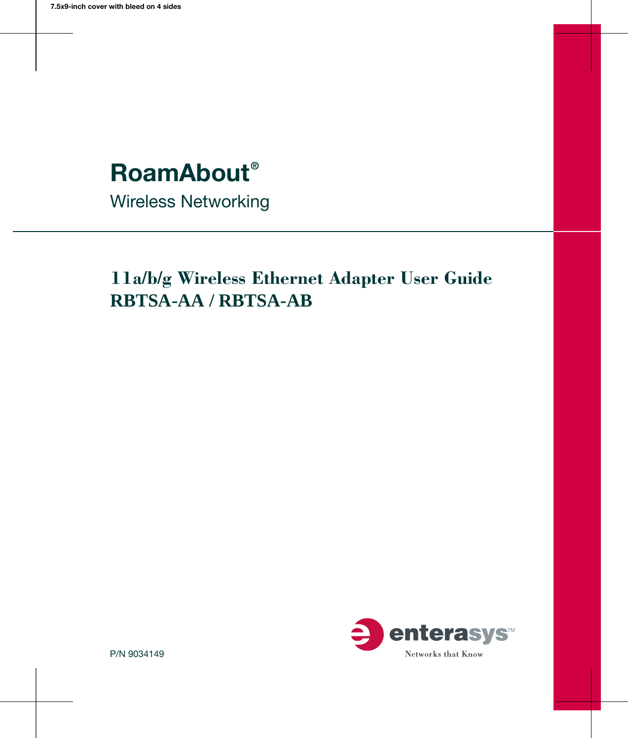

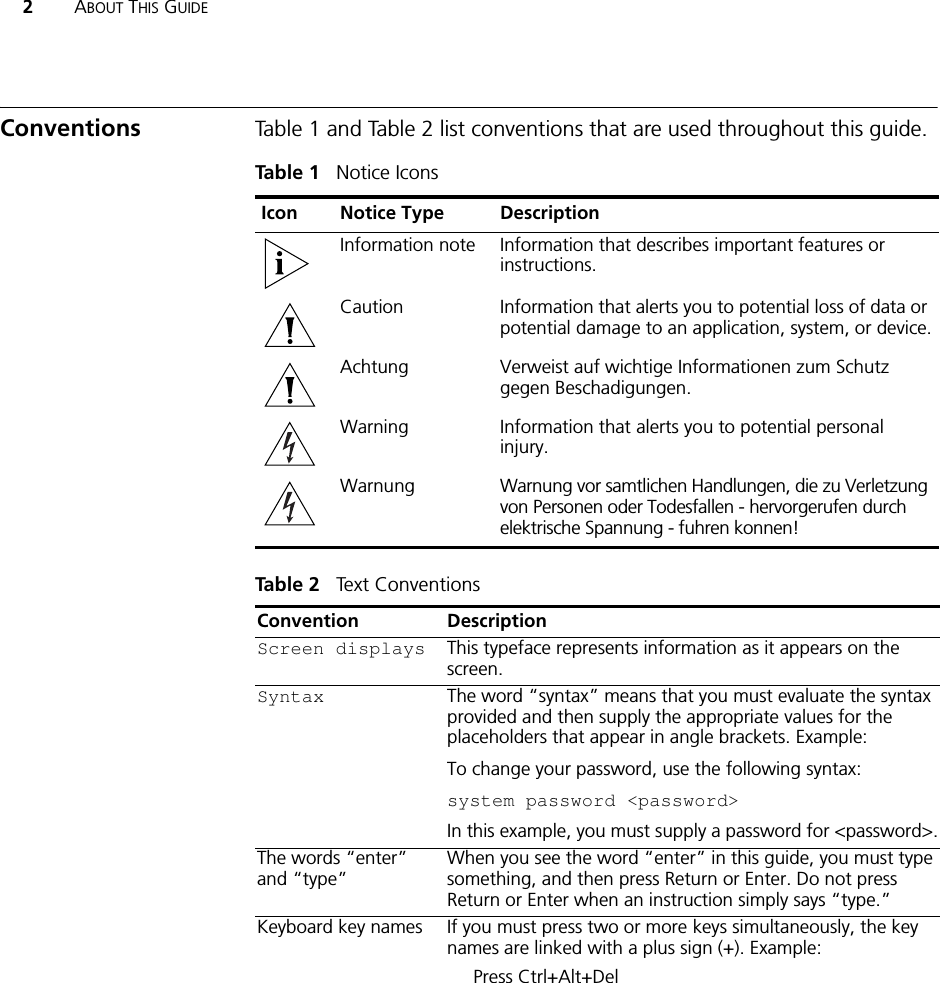

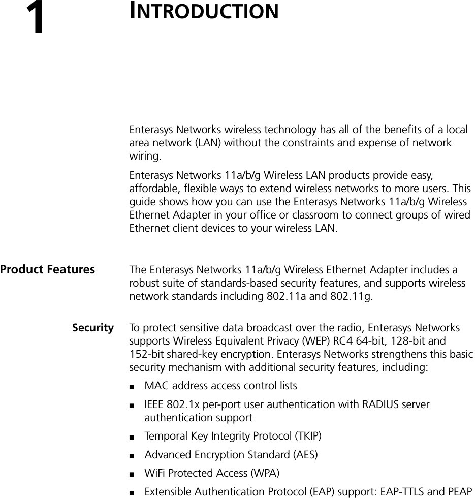
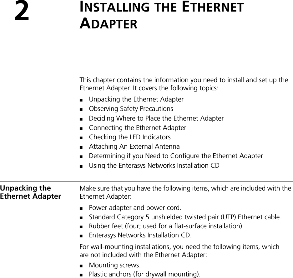
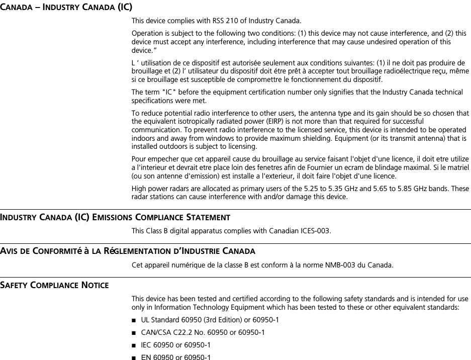
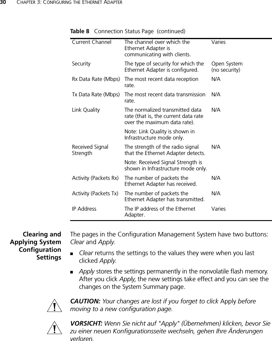
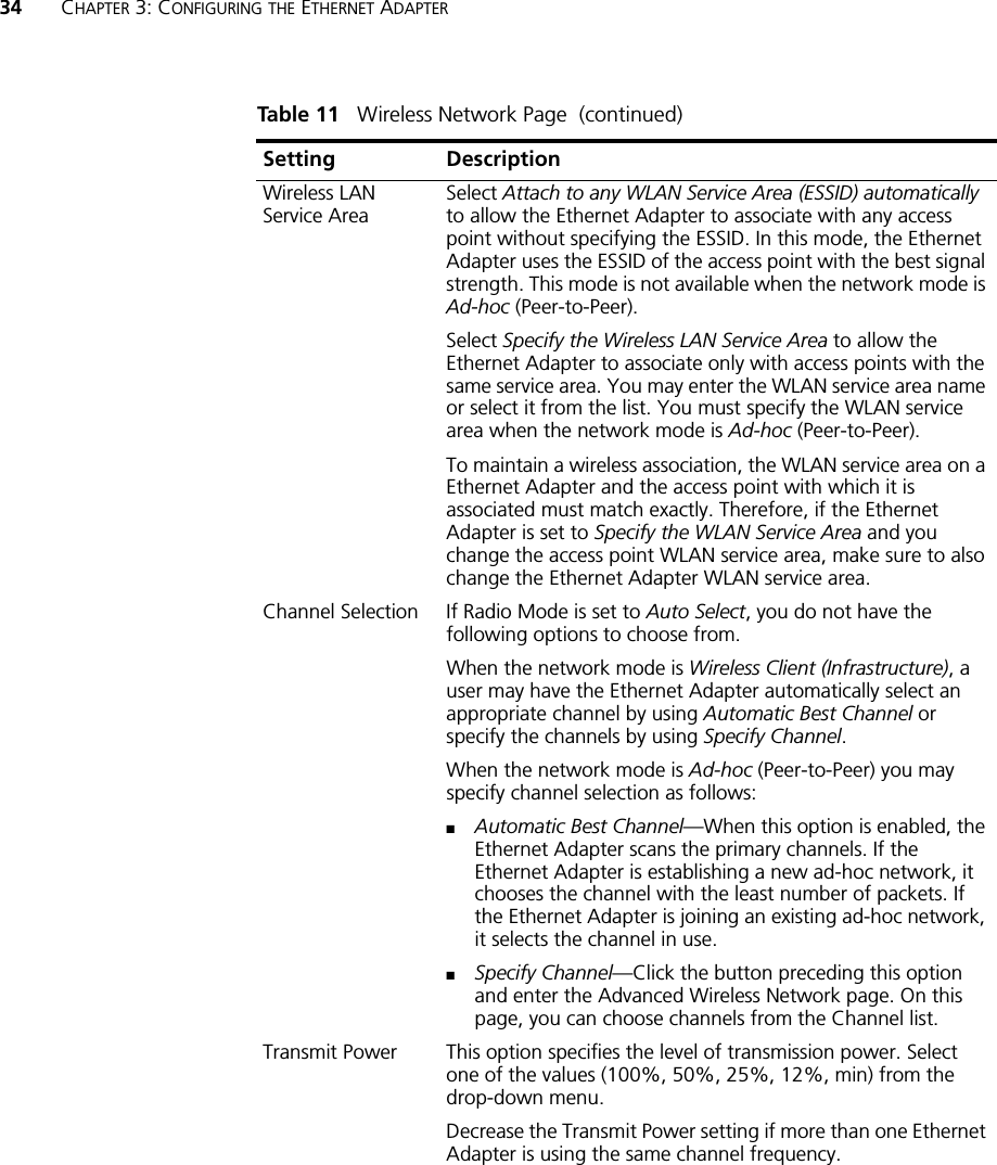
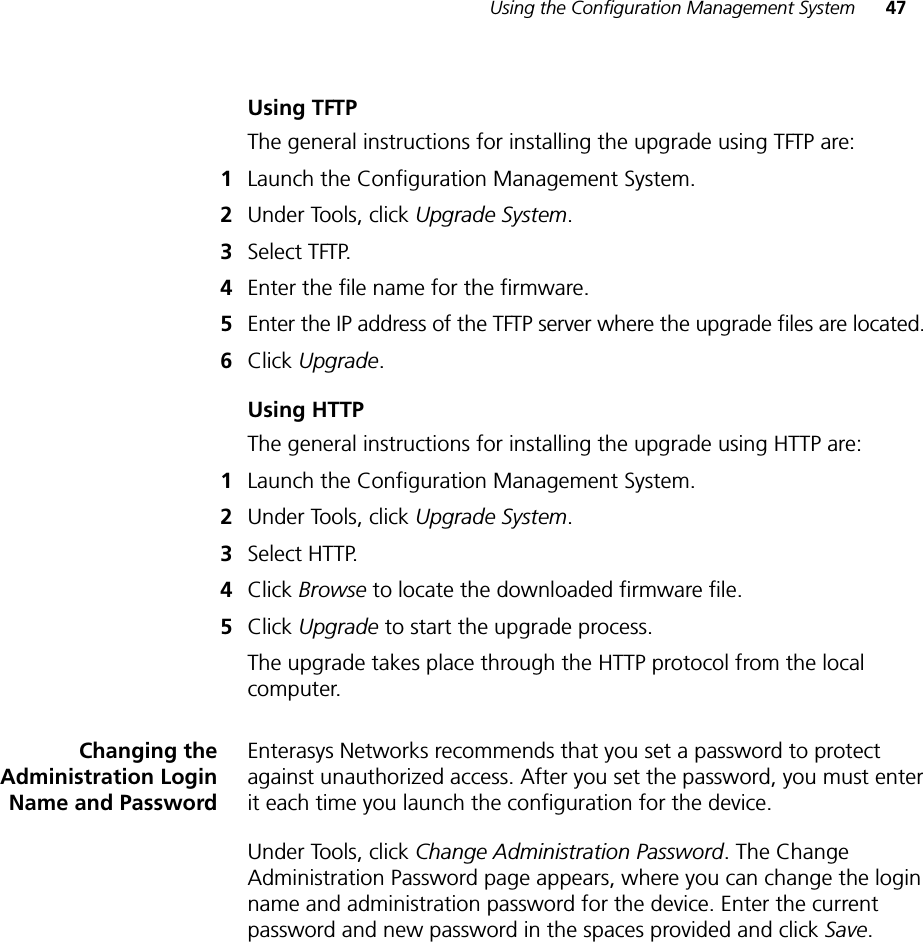
![16 CHAPTER 2: INSTALLING THE ETHERNET ADAPTERConnecting to anEthernet DeviceThe Ethernet Adapter is designed to be connected to an Ethernet client device such as a hub, computer, or printer.CAUTION: To avoid the possibility of a transmission loop situation between the Ethernet Adapter and an access point, which could disrupt network operation, do not connect a Ethernet Adapter that is set in Wireless Client (Infrastructure) mode directly to the LAN (for example, through a wall port or through a hub that is connected directly to the LAN).VORSICHT: Um eine Übertragungsschleife zwischen dem Ethernet-Adapter und einem Access Point zu verhindern, die den Netzwerkbetrieb stören könnte, darf ein im Modus Wireless Client (Infrastructure) (Drahtloser Client [Infrastruktur]) eingerichteter Ethernet-Adapter nicht direkt mit dem LAN verbunden werden (z. B. über eine Wandbuchse oder über einen direkt mit dem LAN verbundenen Hub).About the Client List The Ethernet Adapter supports up to 16 specific Ethernet client devices. It uses a client list of MAC addresses to keep track of specific devices that have been connected. After 16 different devices have been connected, the client list is full, and you must clear it before the next new device can associate with the network through the Ethernet Adapter. To clear the list, you must access the Ethernet Adapter’s Configuration Management System. Details are in “Clearing the Ethernet Client List” on page 49.](https://usermanual.wiki/Extreme-Networks/RBTSAAA/User-Guide-557755-Page-22.png)
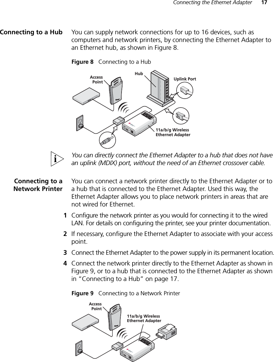
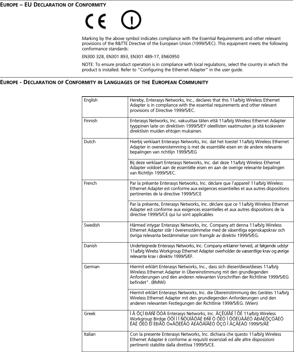
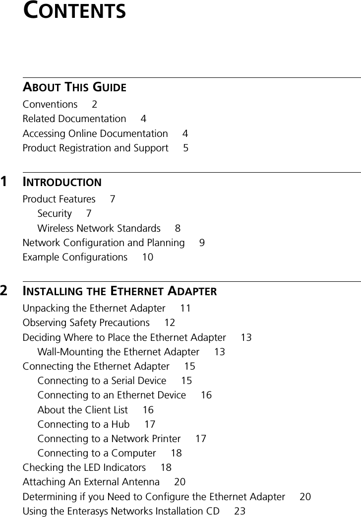
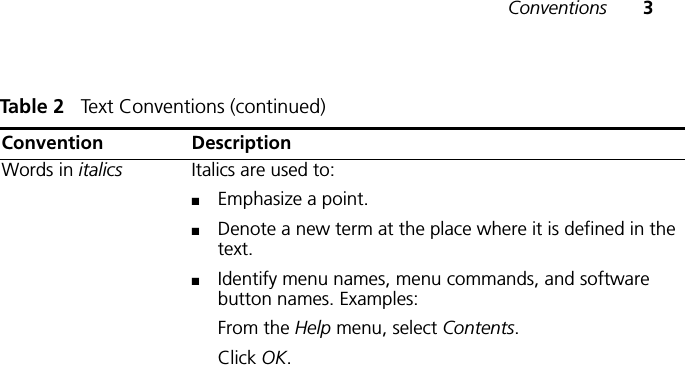
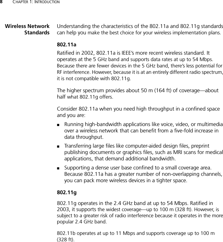
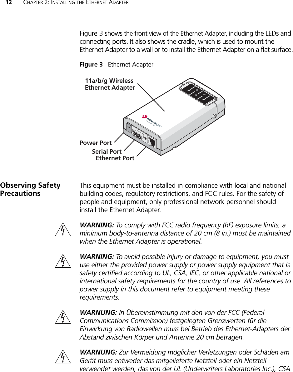
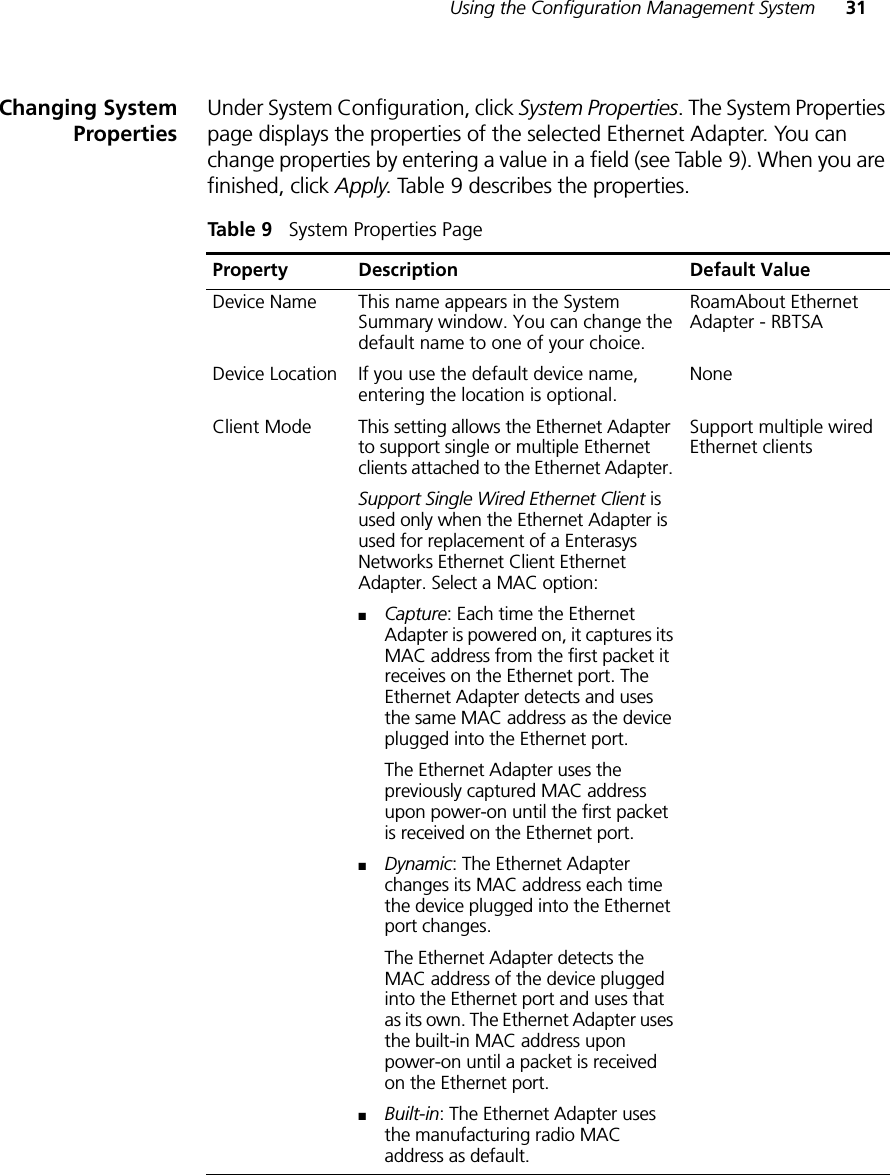
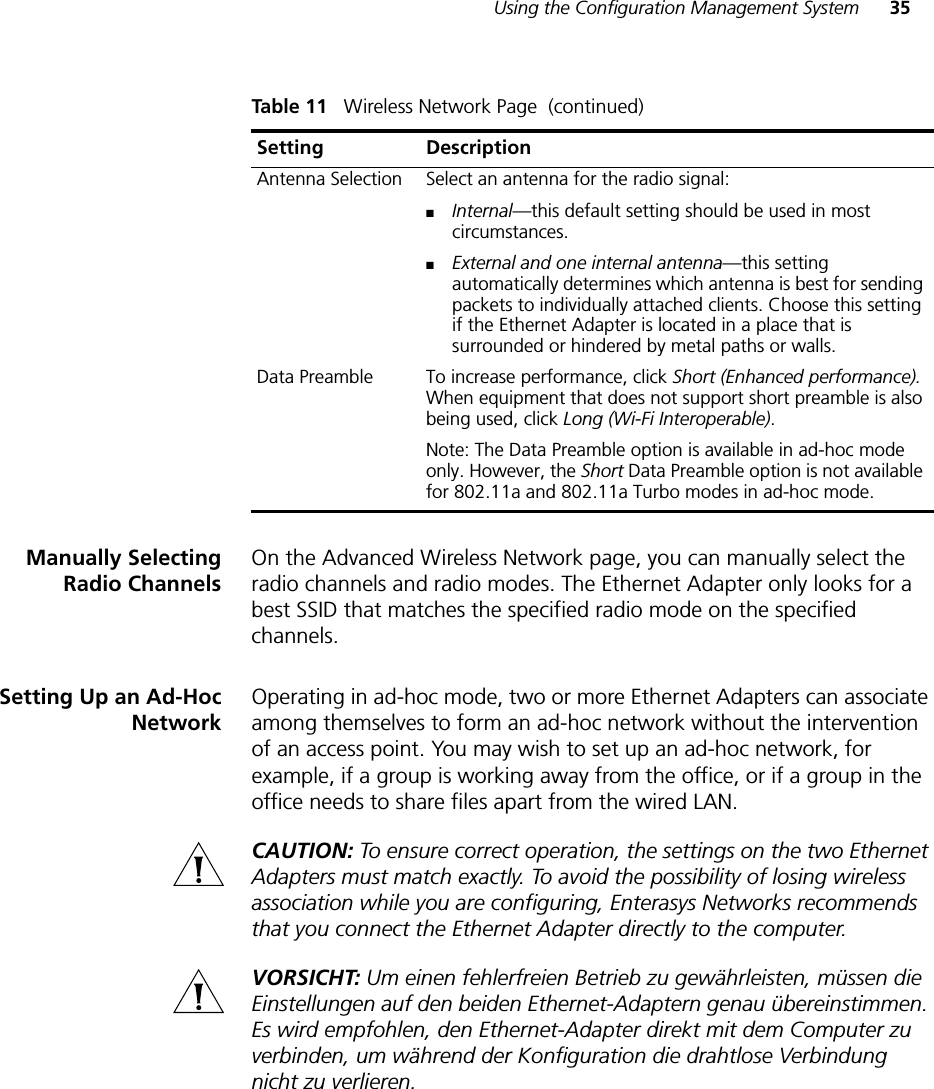
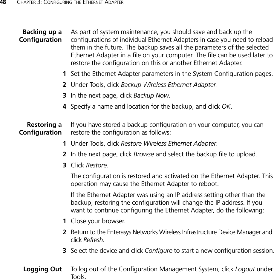
![22 CHAPTER 2: INSTALLING THE ETHERNET ADAPTEREthernet Adapter Default SettingsTable 4 shows the Ethernet Adapter configuration factory defaults.Table 4 Factory Default SettingsProperty Default SettingDevice Name RoamAbout Ethernet Adapter - RBTSADevice Location None (blank)Country For U.S. version, United States and CanadaFor non-U.S. version, set by the userClient Mode Support multiple wired Ethernet clientsIP Network Setting Obtain IP address automatically IP Address Obtained automatically (with a DHCP server)169.254.2.2 (without a DHCP server)Subnet Mask Obtained automatically (with a DHCP server)255.255.0.0 (without a DHCP server)Gateway IP Address Obtained automatically (with a DHCP server)0.0.0.0 (without a DHCP server)Network Mode Wireless Client (Infrastructure)Radio Mode Auto SelectWireless LAN Service Area Attach to any WLAN Service Area (ESSID) automaticallyChannel Selection Automatic Best Channel (uses access point setting)Transmit Power 100%Antenna Selection InternalData Preamble Long (if Network Mode is set to Ad-Hoc)Same as access point setting (if Network Mode is set to Wireless Client [Infrastructure])Security Setting Open System (no security)802.1x Authentication State DisabledSNMP EnabledAccess Control List DisabledAdministration Login Name adminAdministration Password None (blank)TFTP Server IP Address NoneFTP Server IP Address None](https://usermanual.wiki/Extreme-Networks/RBTSAAA/User-Guide-557755-Page-28.png)

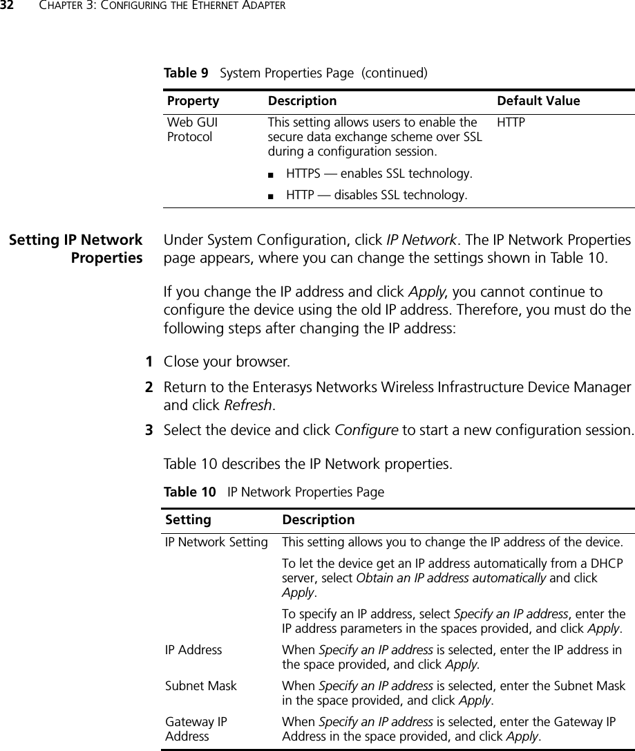
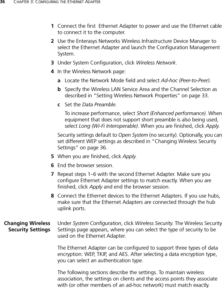

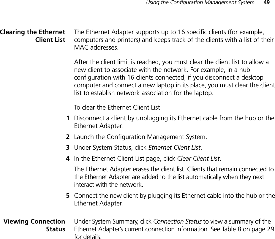
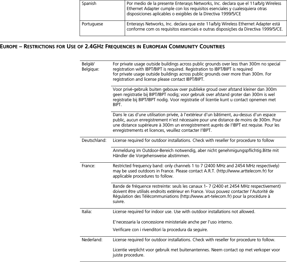
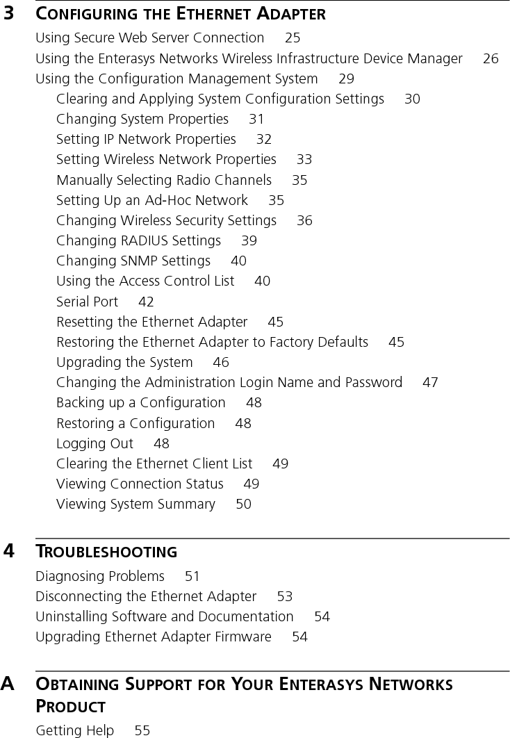
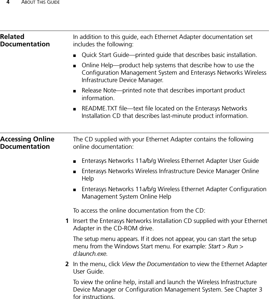
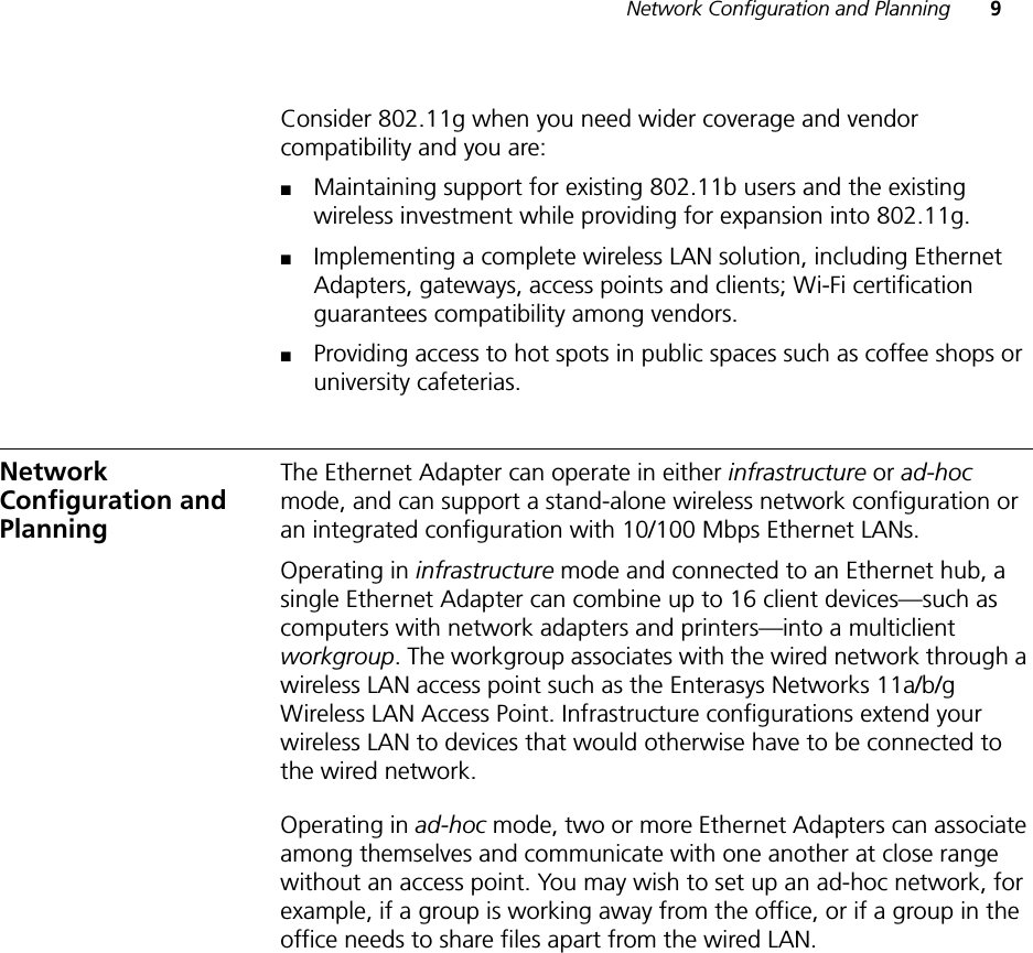
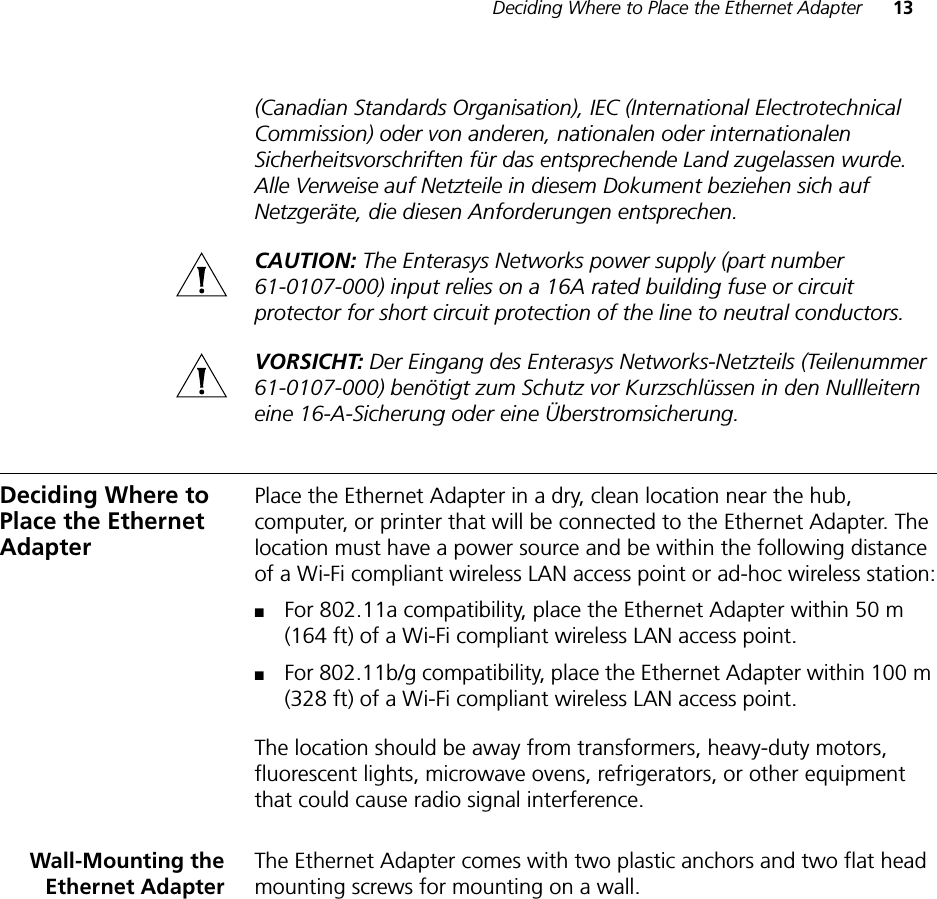
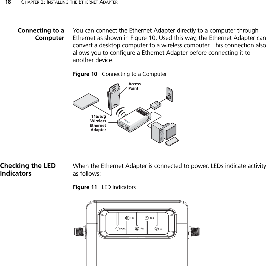
![50 CHAPTER 3: CONFIGURING THE ETHERNET ADAPTERViewing SystemSummaryUnder System Summary, you can view the following information:Click Refresh to update the information.Table 14 System Summary PageProperty Description Default ValueDevice Name The name assigned to the Ethernet Adapter. You can change the default name to one of your choice by clicking System Properties under System Configuration.RoamAbout Ethernet Adapter - RBTSADevice Location If you use the default device name, entering the location is optional. NoneCountry Code The Country Code determines the available channels and transmission power level based on regulatory restrictions in the county where the Ethernet Adapter is installed. VariesTransmit Power The level of transmission power (100%, 50%, 25%, 12%, or Min). You can change this setting by clicking Wireless Network under System Configuration.100%MAC Address The MAC address of the Ethernet Adapter. N/ASerial Number The serial number of the Ethernet Adapter. VariesFirmware Version The version of firmware the Ethernet Adapter is currently using. N/ADHCP Client Determines if the Ethernet Adapter obtains its IP address from the DHCP server on the network.OnIP Address The IP address of the Ethernet Adapter. You can change this address by clicking IP Network under System Configuration.VariesSubnet Mask The subnet mask address of the Ethernet Adapter. You can change this address by clicking IP Network under System Configuration.VariesData Preamble The data preamble setting (Short [Enhanced performance] or Long [Wi-Fi Interoperable]).To change this setting, click Wireless Network under System Configuration.LongSystem Up Time The elapsed time since the Ethernet Adapter booted up. Day 0, 0:00:00Date Manufactured The date the Ethernet Adapter was manufactured. N/A](https://usermanual.wiki/Extreme-Networks/RBTSAAA/User-Guide-557755-Page-56.png)
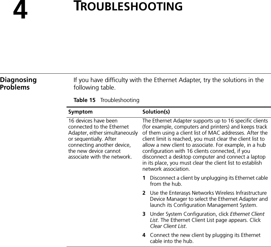
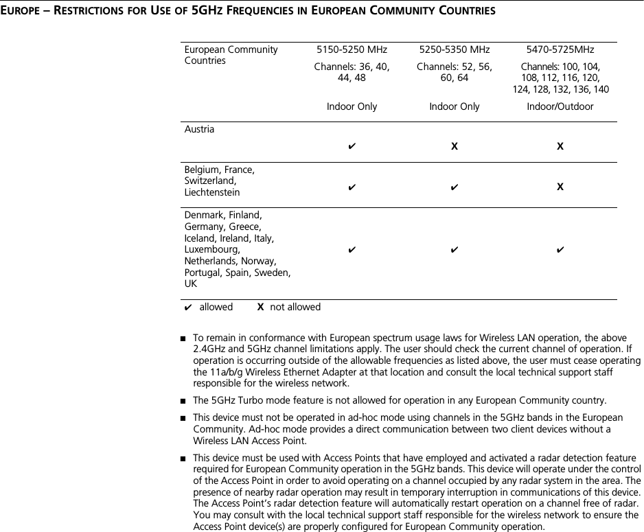
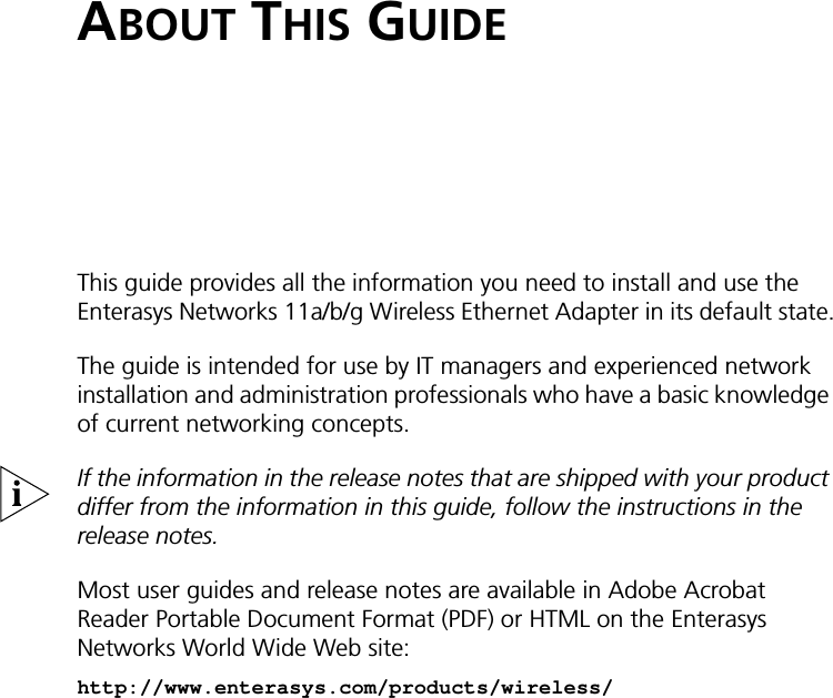
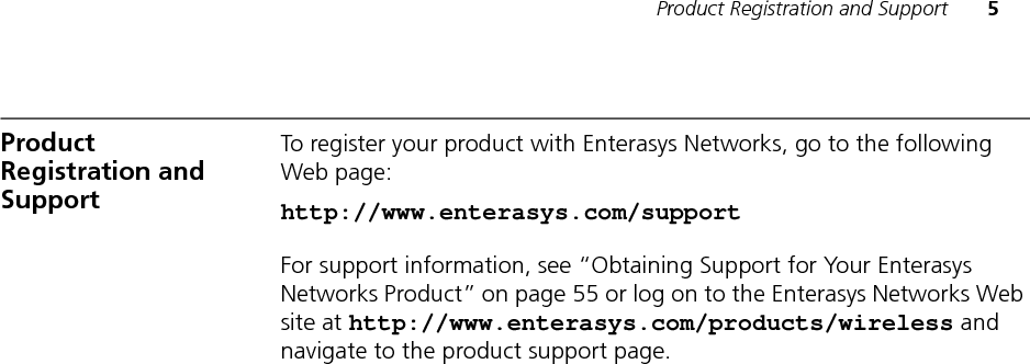
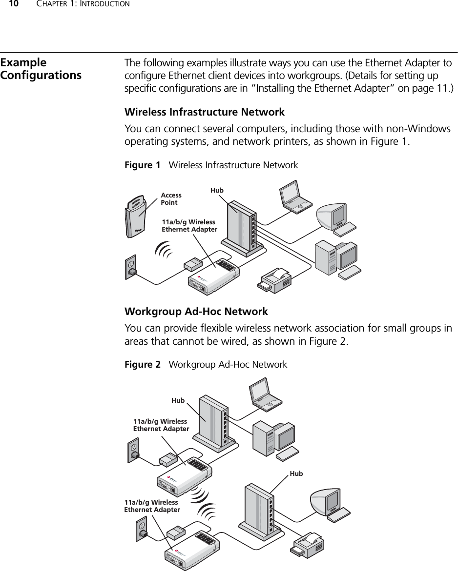
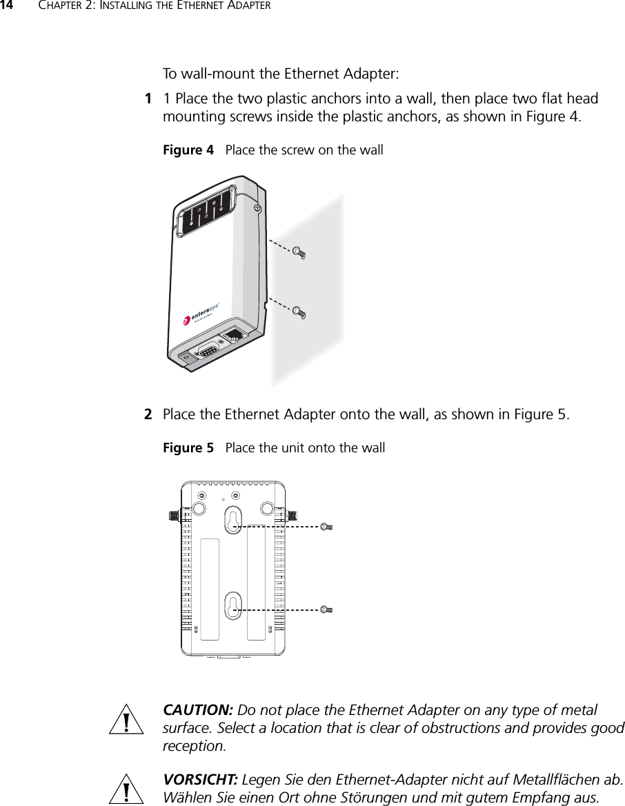
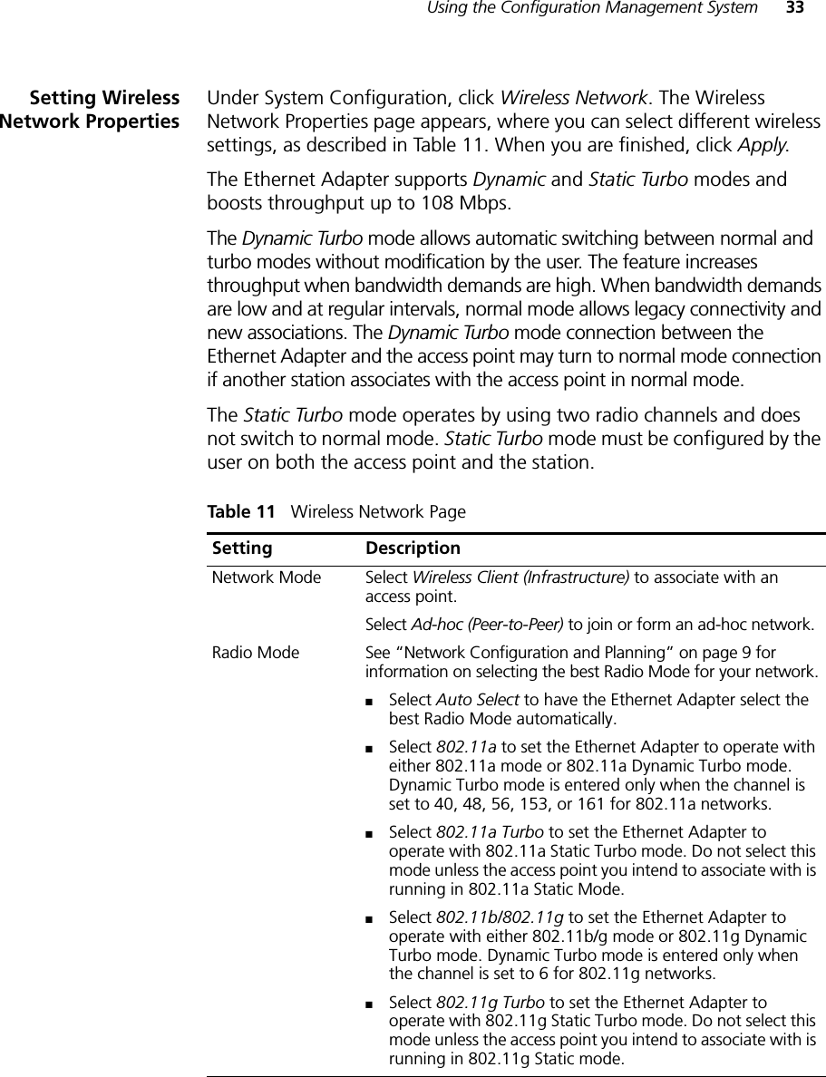
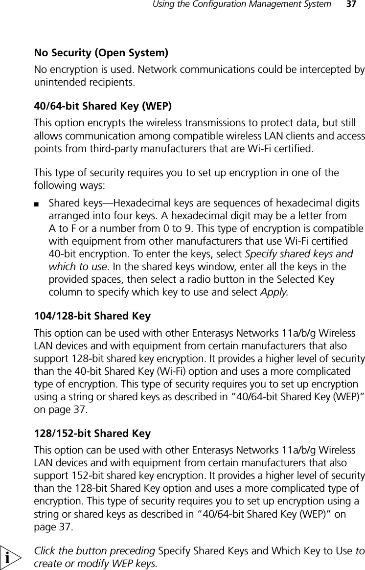
![AOBTAINING SUPPORT FOR YOUR ENTERASYS NETWORKS PRODUCTGetting Help For additional support related to this device or document, contact Enterasys Networks using one of the following methods.Before calling Enterasys Networks, please have the following information ready:■Your Enterasys Networks service contract number■A description of the failure■A description of any action(s) already taken to resolve the problem■The serial and revision numbers of all involved Enterasys Networks products in the network■A description of your network environment (for example, layout and cable type.)■Network load and frame size at the time of trouble (if known)World Wide Web: www.enterasys.com/supportPhone: (603) 332-94001-800-872-8440 (toll-free in the U.S. and Canada)For the Enterasys Networks Support toll-free number in your country:www.enterasys.com/support/gtac-all.htmlEmail: support@enterasys.comTo expedite your message, please type [wireless] in the subject line.To send comments or suggestions concerning this document to the Technical Publications Department: techpubs@enterasys.comTo expedite your message, please include the document Part Number in the email message.](https://usermanual.wiki/Extreme-Networks/RBTSAAA/User-Guide-557755-Page-61.png)