Extricom EXRP-20 802.11a/b/g Access Point User Manual Manual
Extricom Ltd 802.11a/b/g Access Point Manual
UserManual.wiki
>
Extricom
>
EXRP 20 User Manual
Manual
Navigation menu
Upload a User Manual
Namespaces
Wiki Guide
HTML
PDF
Info
Views
User Manual
Discussion / Help
Navigation


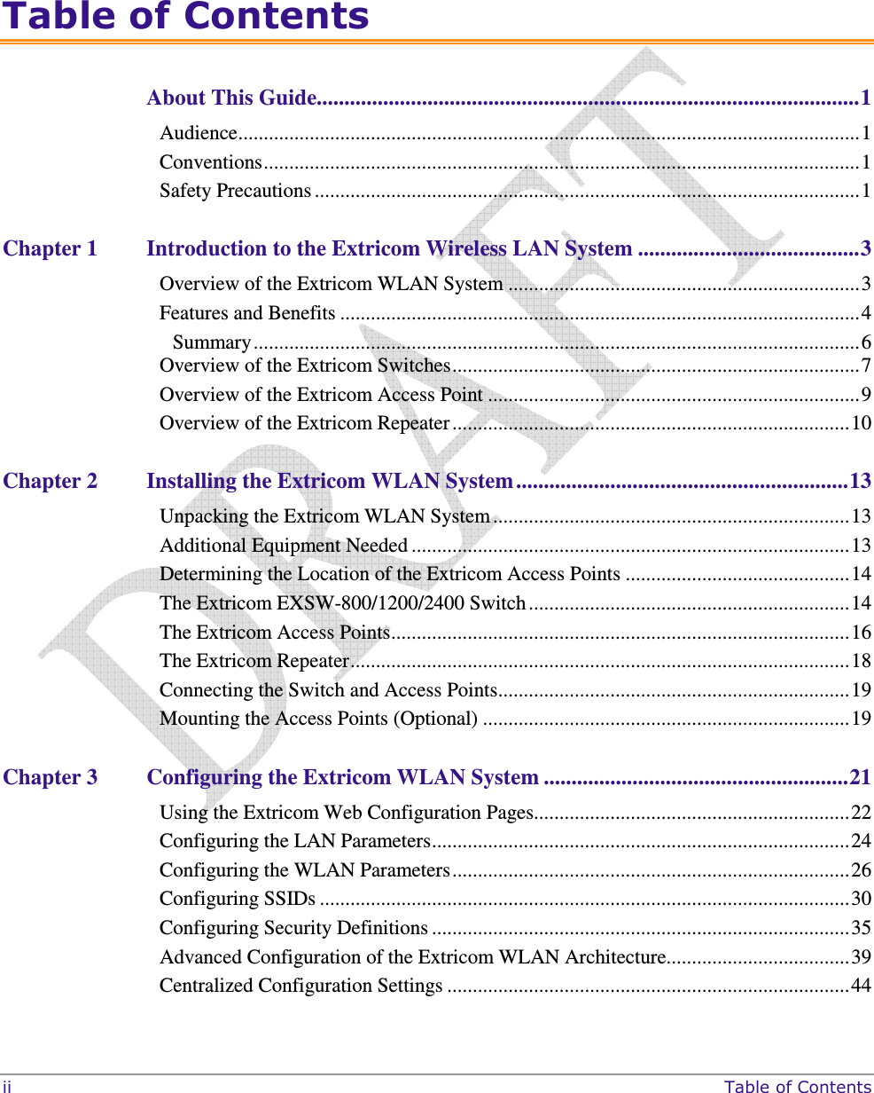
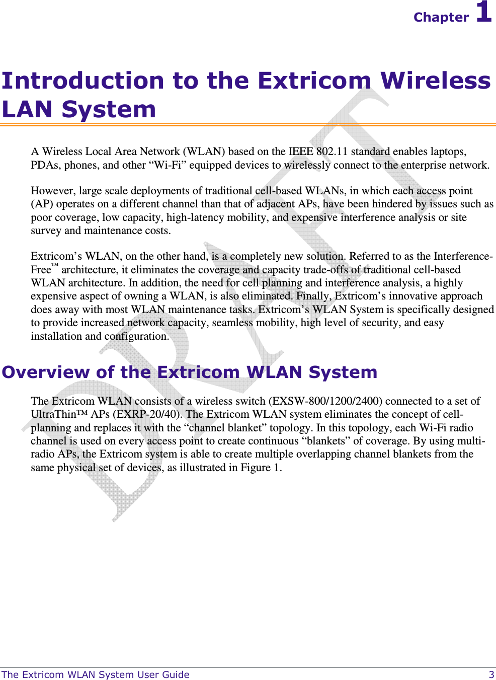
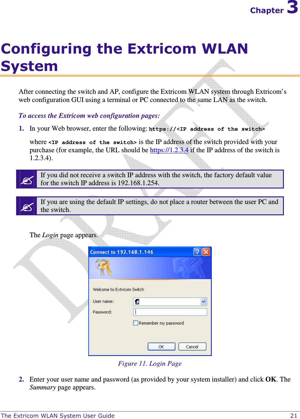
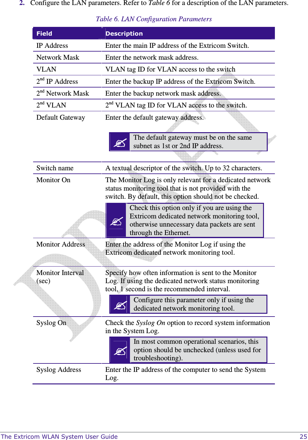
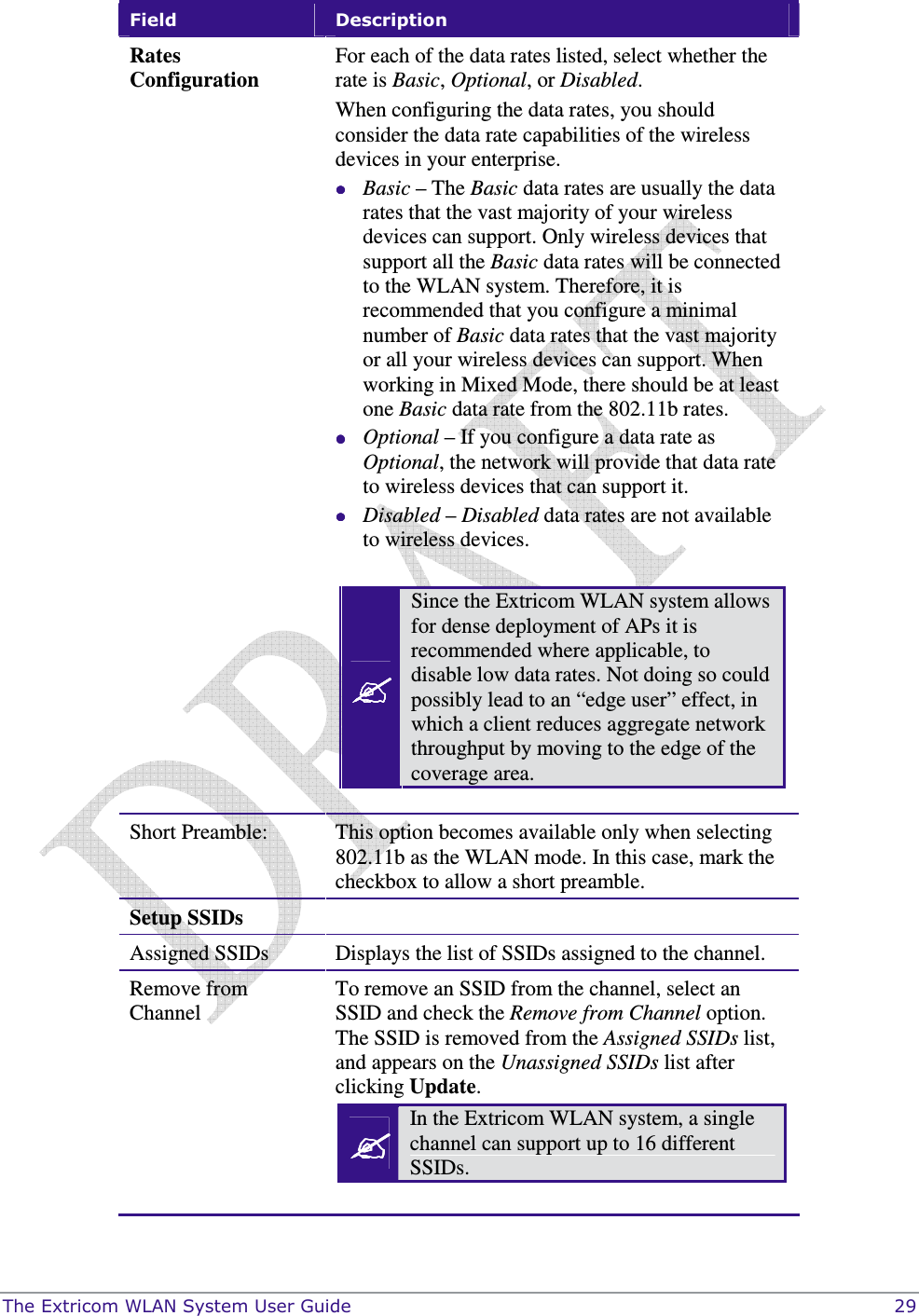
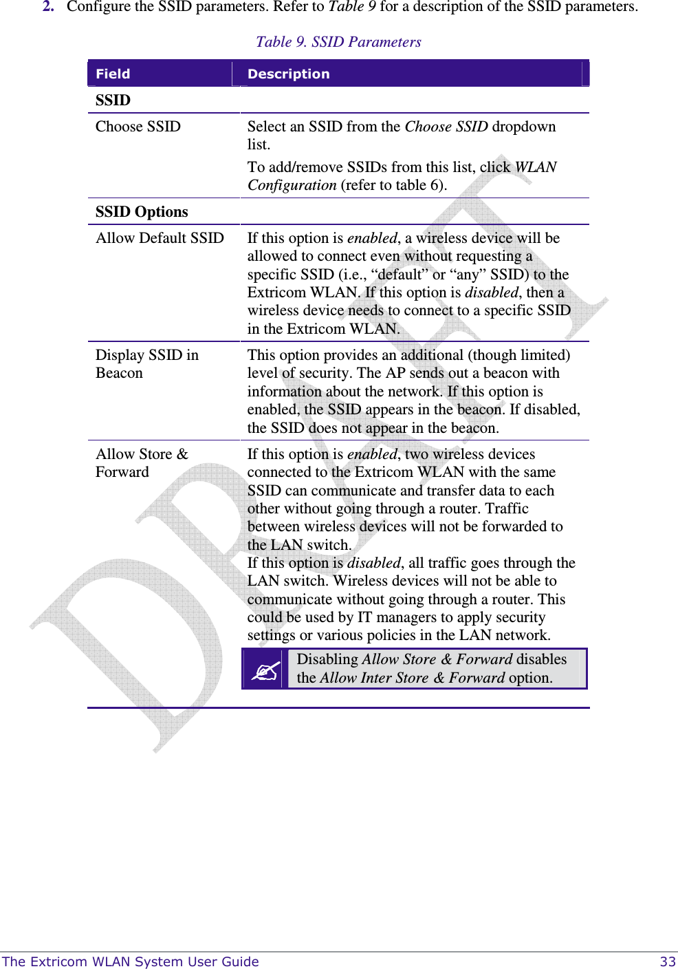
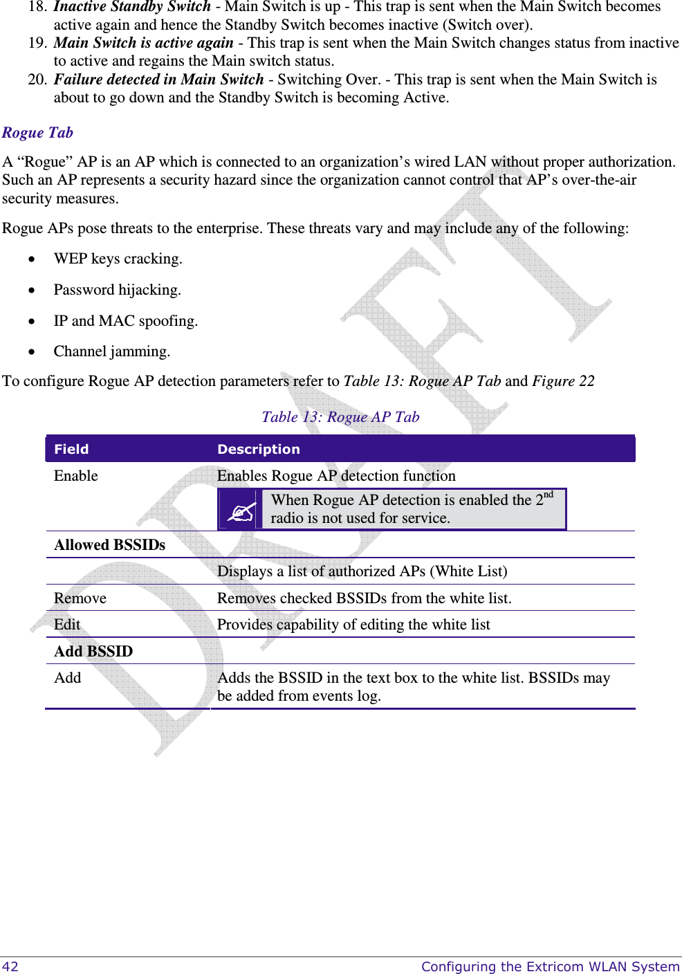
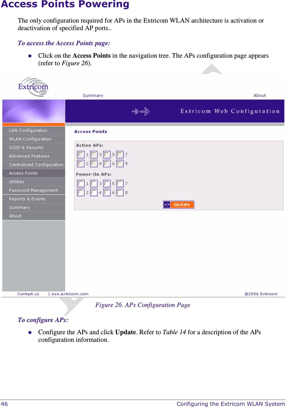
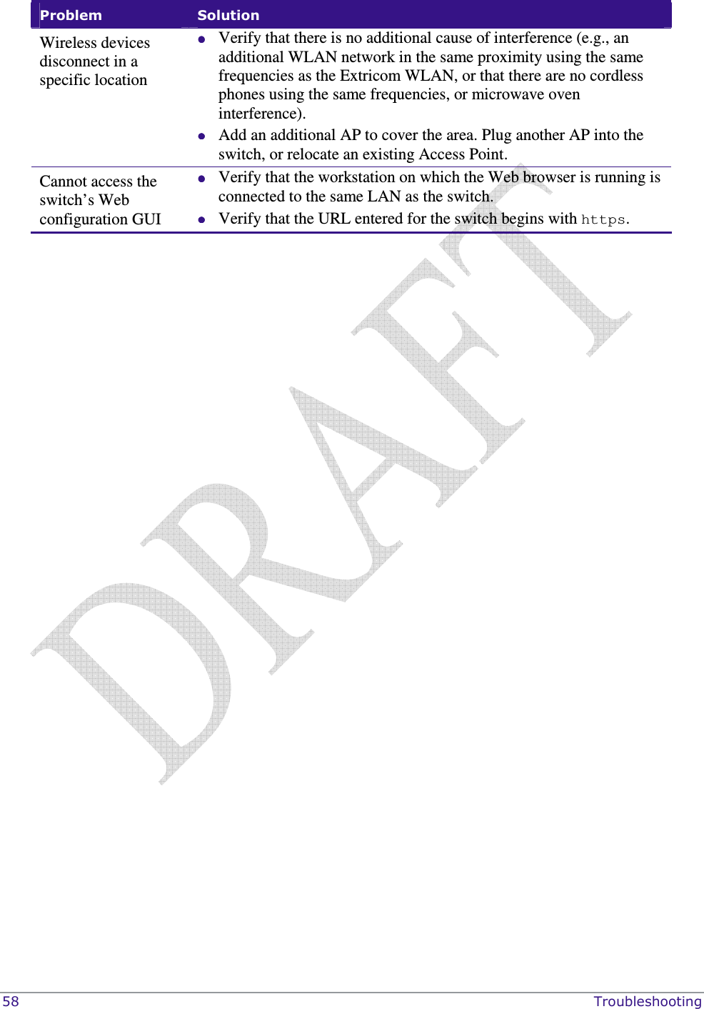
![The Extricom WLAN System User Guide 41 Field Description SNMP Enable Traps Check this option to enable SNMP traps. Community name Enter the community name. Manager IP Enter the manager’s IP address. At present, the following Traps are sent from the Extricom switch to the device on the LAN running the SNMP manager. 1. Client <Client MAC> has associated to <SSID> - This trap is sent after successful association with the client MAC address and the SSID the client associated to. 2. Client <Client MAC> has disassociated from <SSID>. Reason: <Reason> - This trap is sent after client disassociation/disconnection from an SSID. The reason code is an 802.11 reason code. 3. Key error! Client: <Client MAC> - SSID: <SSID> - Cipher suite: <Cipher> - This trap is sent in case of any key error during four-way handshake (MIC error) or as a result of any key error when receiving data from client.. 4. New Rogue Detected <BSSID><Port><Radio><Channel><RSSI> - This trap is sent when a new Rogue AP is detected. The trap includes the AP’s BSSID, the switch port which detected the Rogue AP, the channel of the Rogue AP and the Rogue AP signal level (RSSI). 5. Rogue Updated <BSSID><Port><Radio><Channel><RSSI> - This trap is sent when an existing previously detected Rogue AP is re-detected with change in one of its parameters. The trap includes the AP’s BSSID, the switch port which detected the Rogue AP, the channel of the Rogue AP and the Rogue AP signal level (RSSI). 6. Rogue Removed <BSSID><Port><Radio><Channel><RSSI> - This trap is sent when a new Rogue AP is detected. The trap includes the AP’s BSSID, the switch port which detected the Rogue AP, the channel of the Rogue AP and the Rogue AP signal level (RSSI). 7. RADIUS Timeout <ESSID><# of timeouts> - This trap is sent when the RADIUS timeout had elapsed and includes the ESSID and the number of timeouts that occurred. 8. RADIUS Redundancy Selection Changed <ESSID><#of RADIUS>to<# of RADIUS> - This trap is sent when the RADIUS selection has been changed from one server to another, and includes the ESSID, the number of the previous server and the number of the new server. 9. No RADIUS <ESSID> - This trap is sent when the last RADIUS server failed and includes the ESSID. 10. Configured and connected APs of channel [<channel number>] - This trap provides a summary of all APs and their status. This trap is typically sent after an event of AP removal or connection from/to the switch. 11. AP <ap number in hex base> has been connected - This trap is typically sent after an event of connecting an AP to the switch. 12. AP <ap number in hex base> has been disconnected - This trap is typically sent after an event of disconnecting an AP from the switch. 13. Reference Host is up – This trap is sent when the Reference host is up and active. Sent by the Main switch. 14. Reference Host is down - This trap is sent when the Reference host is down. Sent by the Main Switch. 15. Standby Switch is up - This trap is sent when the Standby Switch is up & active. 16. Standby Switch is down - This trap is sent when the Standby Switch is down. 17. Inactive - Reference Host is down - This trap is sent when the Reference host is down, and hence the Main switch becomes inactive.](https://usermanual.wiki/Extricom/EXRP-20/User-Guide-825182-Page-49.png)