Extricom EXRP-30N 802.11a/b/g/n Wireless Access Point User Manual manual pt 2
Extricom Ltd 802.11a/b/g/n Wireless Access Point manual pt 2
UserManual.wiki
>
Extricom
>
EXRP-30N User Manual
>
manual pt 2
Contents
1.
manual pt 1
2.
manual pt 2
manual pt 2
Navigation menu
Upload a User Manual
Namespaces
Wiki Guide
HTML
PDF
Info
Views
User Manual
Discussion / Help
Navigation
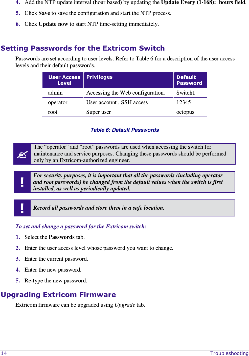
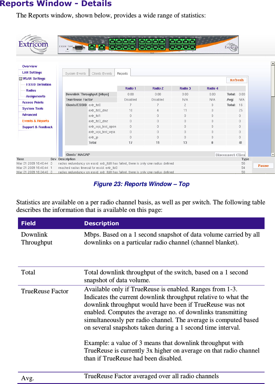
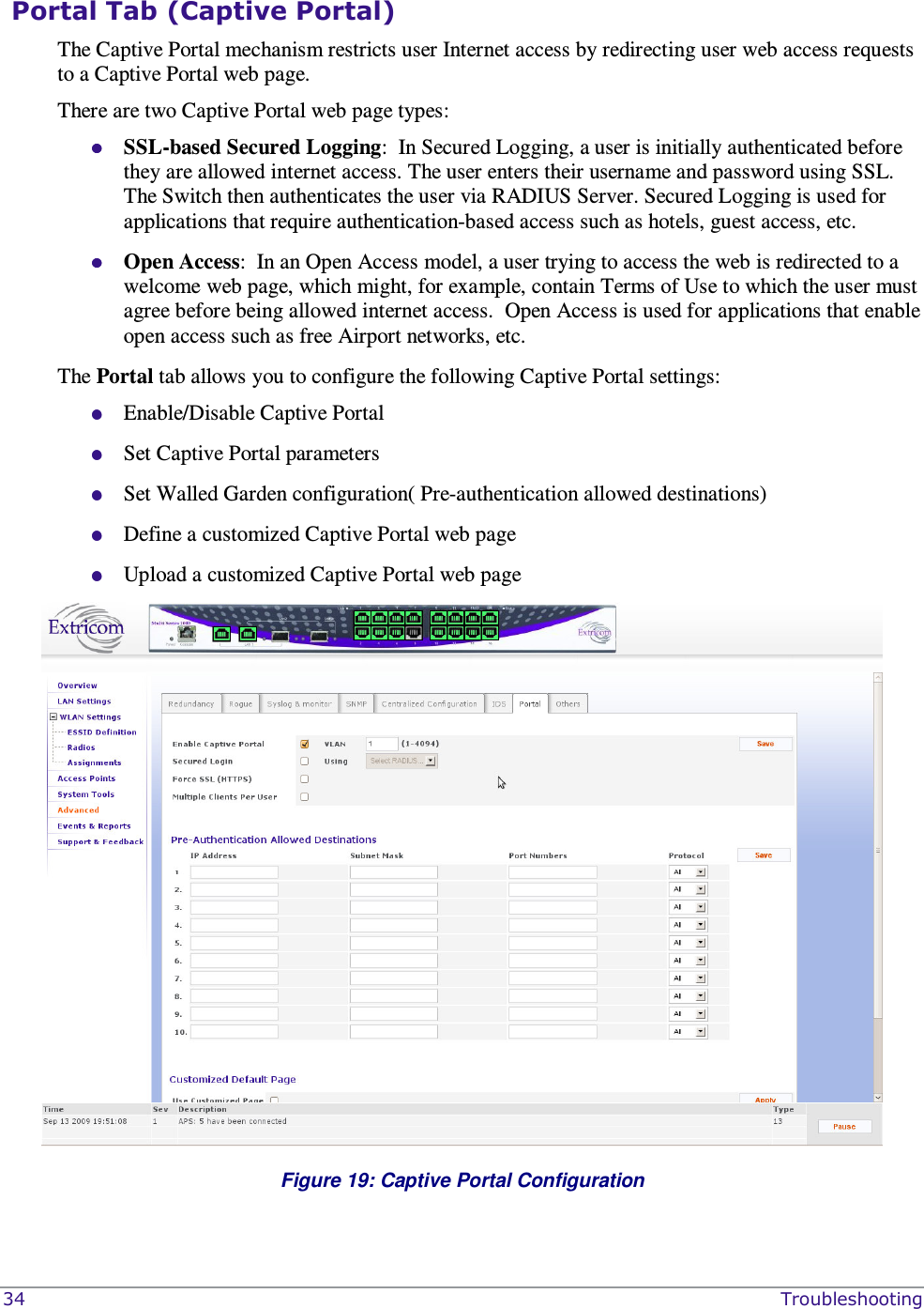
![28 Troubleshooting Field Description Enable Traps Check this option to enable SNMP traps over the northbound interface. Community name Enter the community name. Manager IP Enter the manager’s IP address. Table 13: SNMP Configuration Features The following is a subset of the traps that are sent northbound from the Extricom switch when Enable Traps is checked: 1. Client <Client MAC> has associated to <ESSID> - This trap is sent after successful association with the client MAC address and the ESSID the client associated to. 2. Client <Client MAC> has disassociated from <ESSID>. Reason: <Reason> - This trap is sent after client disassociation/disconnection from an ESSID. The reason code is an 802.11 reason code. 3. Client: <Client MAC> - ESSID: <ESSID> - Cipher suite: <Cipher> - This trap is sent in case of any key error during four-way handshake (MIC error) or as a result of any key error when receiving data from client. 4. New Rogue Detected <BSSID><Port><Radio><Channel><RSSI> - This trap is sent when a new Rogue AP is detected. The trap includes the AP’s BSSID, the switch port which detected the Rogue AP, the channel of the Rogue AP and the Rogue AP signal level (RSSI). 5. Rogue Updated <BSSID><Port><Radio><Channel><RSSI> - This trap is sent when an existing previously detected Rogue AP is re-detected with change in one of its parameters. The trap includes the AP’s BSSID, the switch port which detected the Rogue AP, the channel of the Rogue AP and the Rogue AP signal level (RSSI). 6. Rogue Removed <BSSID><Port><Radio><Channel><RSSI> - This trap is sent when a new Rogue AP is detected. The trap includes the AP’s BSSID, the switch port which detected the Rogue AP, the channel of the Rogue AP and the Rogue AP signal level (RSSI). 7. RADIUS Timeout <ESSID><# of timeouts> - This trap is sent when the RADIUS timeout had elapsed and includes the ESSID and the number of timeouts that occurred. 8. RADIUS Redundancy Selection Changed <ESSID><#of RADIUS>to<# of RADIUS> - This trap is sent when the RADIUS selection has been changed from one server to another, and includes the ESSID, the number of the previous server and the number of the new server. 9. No RADIUS <ESSID> - This trap is sent when the last RADIUS server failed and includes the ESSID. 10. Configured and connected APs of channel [<channel number>] - This trap provides a summary of all APs and their status. This trap is typically sent after an event of AP removal or connection from/to the switch. 11. AP <ap number in hex base> has been connected - This trap is typically sent after an event of connecting an AP to the switch. 12. AP <ap number in hex base> has been disconnected - This trap is typically sent after an event of disconnecting an AP from the switch. 13. Reference Host is up – This trap is sent when the Reference host is up and active. Sent by the Main switch. 14. Reference Host is down - This trap is sent when the Reference host is down. Sent by the Main Switch. 15. Standby Switch is up - This trap is sent when the Standby Switch is up & active.](https://usermanual.wiki/Extricom/EXRP-30N.manual-pt-2/User-Guide-1243026-Page-28.png)
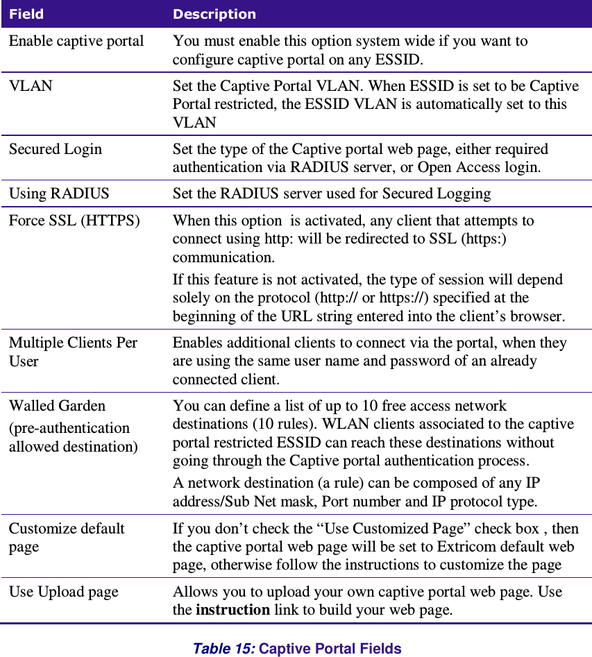

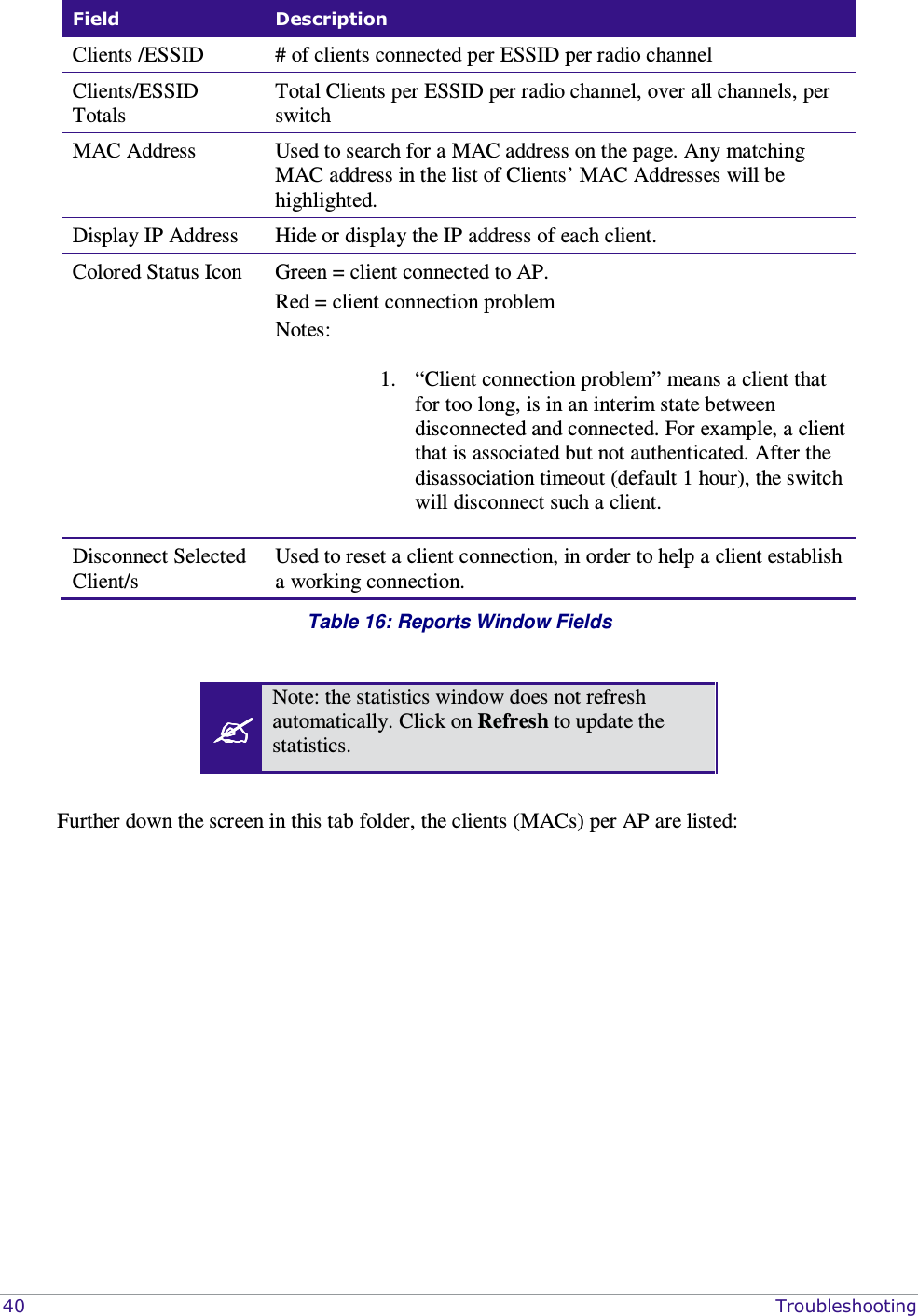
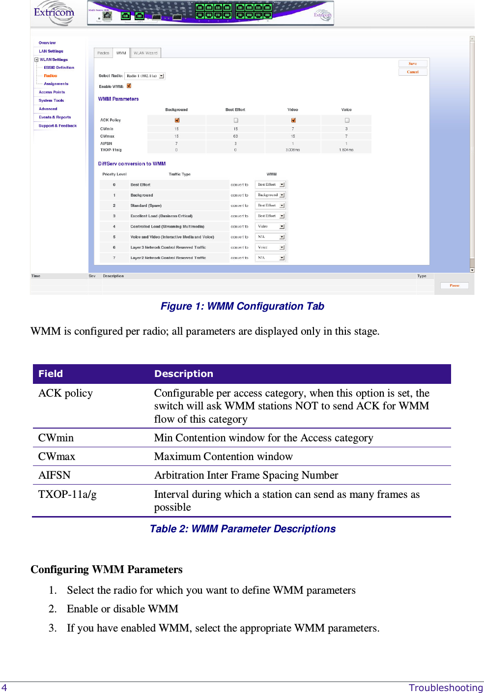
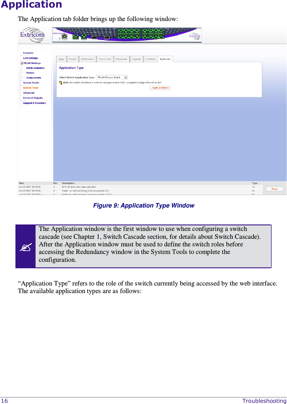
![Others Tab This tab provides other advanced configuration functions such as AeroScout and 802.11d. Select the 802.11d Support check box if you wish to enable this option. You can enable it per ESSID or for all ESSIDs. Select the AeroScout Support check box if you wish to enable this option. Select the In Band management check box if you wish to enable this option (This is a general enable for the option and requires per ESSDI configuration). Rate Adaptation algorithm fine-tuning o Set Rate adaptation offset [0-20] (default is 0) – The Rate adaptation algorithm is based on received RSSI values. This parameter will change the sensitivity of the effect of RSSI value changes on the rate adaptation. The higher the value the less sensitive it will be. o Set RSSI aging (default is 15) - This parameter determines the period of time to wait before switching to the lowest rate if no RSSI information is received from a client. This is measured in multiplication of 100msec (every beacon interval) Select PCI enhanced mode (Checked by default) – This is related to different HW versions of the EXRP boards. If the Access Points don’t function , uncheck this selection (notify the Extricom support team ) To activate these options per ESSID, after selecting the above check boxes go to the WLAN Settings page. Figure 21: Other Configuration Tab](https://usermanual.wiki/Extricom/EXRP-30N.manual-pt-2/User-Guide-1243026-Page-37.png)