Extricom EXRP-20 802.11a/b/g Access Point User Manual Manual
Extricom Ltd 802.11a/b/g Access Point Manual
Extricom >
Manual

Version 3.1
EXTRICOM WLAN SYSTEM
USER GUIDE
EXSW-800
EXSW-1200
EXSW-2400
EXRP-20
EXRP-40
EXRE-10


Copyright
No part of this publication may be reproduced, stored in a retrieval system or transmitted, in any
form or by any means, photocopying, recording or otherwise, without prior written consent of
Extricom Ltd. No patent liability is assumed with respect to the use of the information contained
herein.
While every precaution has been taken in the preparation of this publication, Extricom Ltd. assumes
no responsibility for errors or omissions. The information contained in this publication and features
described herein are subject to change without notice. Extricom Ltd. reserves the right at any time
and without notice, to make changes in the product.
Copyright © 2007 Extricom Ltd. All rights reserved. The products described herein are protected
by U.S. Patents and may be protected by other foreign patents, or pending applications.
Important Notice:
Read this user manual and safety instructions before installing and operating the
Extricom WLAN system.
Disclaimer
Extricom makes no representations or warranties, whether express or implied, that the
Extricom wireless local area network (WLAN) system or any component thereof shall meet
the purchaser’s operating requirements or that system operation will be uninterrupted or
errorfree. All WLANs, including the Extricom WLAN system, can potentially be affected by
outside sources of interference such as other broadcasting devices, radiation, device immunity
level, and other external sources of interference.

The Extricom WLAN System User Guide i
Declaration of Conformity
Manufacturer’s Name: Extricom Ltd.
Declares under our sole responsibility that the products:
Product Names: Extricom EXSW-800 & EXSW-1200 & EXSW-2400 & EXRE -10
Conform(s) to the following standard(s) or other normative document(s):
EMC: FCC Part 15 Class B
EN 300386
VCCI V-3/2001.04
ANATEL Resolution 237
Safety: EN 60950-1
UL 60950-1
IEC 60950-1
ANATEL Resolution 238
Environmental: EU Directive 2002/95/EC of January 27, 2003, on the Restriction of the Use of
Certain Hazardous Substances in Electrical and Electronic Equipment (RoHS)

ii Declaration of Conformity
Manufacturer’s Name: Extricom Ltd.
Declares under our sole responsibility that the product:
Product Name: Extricom EXRP-20 & EXRP-40
Conforms to the following standard(s) or other normative document(s):
EMC: FCC Part 15 Class B
EN 301489
VCCI V-3/2001.04.
Radio: FCC Part 15 C
FCC Part 15 E
EN 300328
EN 301893
Japan Type Certificate: Article 2, clause 1
ANTEL Resolution 365
Safety: EN 60950-1
UL 60950-1
IEC 60950-1
Environmental: EU Directive 2002/95/EC of January 27, 2003, on the Restriction of the Use of
Certain Hazardous Substances in Electrical and Electronic Equipment (RoHS)
This device complies with Part 15 of the FCC Rules. Operation is subject to the
following two conditions:
• The device may not cause harmful interference
• This device must accept any interference received, including
interference that may cause undesired operation.
!
This equipment has been approved for mobile applications where the equipment
should be used at distances greater than 20cm from the human body (with the
exception of hands, wrists, feet and ankles). Operation at distances less than 20 cm
is strictly prohibited.
Changes or modification to device not expressly approved by Extricom LTD is
strictly prohibited and could avoid the user's authority to operate the equipment.

ii Table of Contents
Table of Contents
About This Guide..................................................................................................1
Audience..........................................................................................................................1
Conventions.....................................................................................................................1
Safety Precautions ...........................................................................................................1
Chapter 1 Introduction to the Extricom Wireless LAN System ........................................3
Overview of the Extricom WLAN System .....................................................................3
Features and Benefits ......................................................................................................4
Summary.......................................................................................................................6
Overview of the Extricom Switches................................................................................7
Overview of the Extricom Access Point .........................................................................9
Overview of the Extricom Repeater..............................................................................10
Chapter 2 Installing the Extricom WLAN System ............................................................13
Unpacking the Extricom WLAN System ......................................................................13
Additional Equipment Needed ......................................................................................13
Determining the Location of the Extricom Access Points ............................................14
The Extricom EXSW-800/1200/2400 Switch ...............................................................14
The Extricom Access Points..........................................................................................16
The Extricom Repeater..................................................................................................18
Connecting the Switch and Access Points.....................................................................19
Mounting the Access Points (Optional) ........................................................................19
Chapter 3 Configuring the Extricom WLAN System .......................................................21
Using the Extricom Web Configuration Pages..............................................................22
Configuring the LAN Parameters..................................................................................24
Configuring the WLAN Parameters..............................................................................26
Configuring SSIDs ........................................................................................................30
Configuring Security Definitions ..................................................................................35
Advanced Configuration of the Extricom WLAN Architecture....................................39
Centralized Configuration Settings ...............................................................................44

The Extricom WLAN System User Guide iii
Access Points Powering ................................................................................................46
Configuration of the Extricom WLAN Architecture Utilities.......................................48
Viewing the System Configuration File .....................................................................49
Configuration File Backup..........................................................................................49
Uploading a New Configuration File..........................................................................50
Restoring System Defaults..........................................................................................50
Upgrading the Extricom Firmware .............................................................................50
Rebooting the Extricom Switch..................................................................................51
Reconfigure Switch - Smart Configuration ................................................................51
Setting the Time and Date...........................................................................................51
Setting Passwords in the Extricom Switch....................................................................53
Viewing Reports and Events Log..................................................................................53
Viewing a Summary of the Updated Configuration......................................................54
Viewing Extricom Information .....................................................................................56
Chapter 4 Troubleshooting ..................................................................................................57
Appendix A Specifications...................................................................................................... 59
Extricom Switch Specifications ....................................................................................59
Extricom Access Point Specifications...........................................................................61
Extricom PoE Range extender specificathion ...............................................................64
Appendix B Access Point Mounting Template..................................................................... 65

The Extricom WLAN System User Guide 1
About This Guide
This guide provides detailed instructions for installing, configuring, and troubleshooting the
Extricom EXSW-800/1200/2400 WLAN switches and Extricom EXRP-20/40UltraThin™ Access
Point (AP) .
Audience
This guide is intended for enterprise IT managers and system installers who are familiar with
installing and configuring networks.
Conventions
This is a note. It provides additional information to users.
-
This is a caution. A caution warns of possible damage to the equipment if a
procedure is not followed correctly.
!
A warning alerts you to important operating instructions.
Safety Precautions
Follow the instructions in the guide to ensure proper installation and operation of the switch and
APs.
!
The use of wireless devices is limited to the constraints imposed by local laws.
Operate the switch and APs in an indoor environment.
Disconnect the switch and APs from power sources before servicing.

2 Introduction to the Extricom Wireless LAN System
The switch and AP enclosure must not be opened by anyone other than an authorized
service representative.
To comply with FCC RF exposure compliance requirements, maintain a minimal separation
distance of at least 20 cm/8 inches between the AP and all persons.
The switch contains an internal battery.
!
Always replace the battery with the same type to avoid the risk of explosion.
Dispose of used battery according to the instructions provided with the new battery.

The Extricom WLAN System User Guide 3
Chapter 1
Introduction to the Extricom Wireless
LAN System
A Wireless Local Area Network (WLAN) based on the IEEE 802.11 standard enables laptops,
PDAs, phones, and other “Wi-Fi” equipped devices to wirelessly connect to the enterprise network.
However, large scale deployments of traditional cell-based WLANs, in which each access point
(AP) operates on a different channel than that of adjacent APs, have been hindered by issues such as
poor coverage, low capacity, high-latency mobility, and expensive interference analysis or site
survey and maintenance costs.
Extricom’s WLAN, on the other hand, is a completely new solution. Referred to as the Interference-
Free™ architecture, it eliminates the coverage and capacity trade-offs of traditional cell-based
WLAN architecture. In addition, the need for cell planning and interference analysis, a highly
expensive aspect of owning a WLAN, is also eliminated. Finally, Extricom’s innovative approach
does away with most WLAN maintenance tasks. Extricom’s WLAN System is specifically designed
to provide increased network capacity, seamless mobility, high level of security, and easy
installation and configuration.
Overview of the Extricom WLAN System
The Extricom WLAN consists of a wireless switch (EXSW-800/1200/2400) connected to a set of
UltraThin™ APs (EXRP-20/40). The Extricom WLAN system eliminates the concept of cell-
planning and replaces it with the “channel blanket” topology. In this topology, each Wi-Fi radio
channel is used on every access point to create continuous “blankets” of coverage. By using multi-
radio APs, the Extricom system is able to create multiple overlapping channel blankets from the
same physical set of devices, as illustrated in Figure 1.

4 Introduction to the Extricom Wireless LAN System
Figure 1. Two Channel Blanket Coverage
The Extricom solution is based on a fully centralized WLAN architecture, in which the switch
makes all of the decisions for packet delivery on the wireless network. In this configuration, the
access points (APs) simply function as radios, with no software, storage capability, or IP address.
Even the basics of connecting are different: clients associate directly with the switch, not with the
AP. The AP acts as an “RF conduit” to rapidly funnel traffic between the clients and the switch. The
Extricom architecture has essentially centralized the 802.11 logic in the switch, while distributing
the wireless electronics in the APs.
Centralization of the Wi-Fi environment enables enterprises to deploy 802.11a/b/g channels at every
AP, creating multiple overlapping “channel blankets” that leverage each of the radios in the multi-
radio UltraThin AP. Each channel’s bandwidth is delivered across the blanket’s service area (i.e. the
combined coverage of all APs connected to the switch), with interference-free operation and
consistent capacity throughout.
As the client moves throughout the blanket, different APs will be in the best position to serve the
client at different times. The switch always uses the uplink and downlink path that is optimal to
serve the client. While this is going on “behind the scenes,” the client never experiences an AP-to-
AP handoff (i.e. de-association and re-association), resulting in seamless mobility.
Within each channel blanket, the switch avoids co-channel interference by permitting multiple APs
to simultaneously transmit on the same channel only if they won’t interfere with each other. This is
the essence of the TrueReuse™ functionality.
Features and Benefits
Extricom’s WLAN system solution offers the following features:
Ease of deployment - No cell planning
Extricom’s architecture requires no cell planning and experiences no constraints due to RF
interference or channelization. Consequently, Extricom APs can be deployed wherever needed,
in any density or even varying density, to meet the desired end-client service level (stipulated in
terms of connection rate). The traditional site survey is therefore reduced to just physical
equipment installation planning.

The Extricom WLAN System User Guide 5
Multi-Layer WLAN
Using multiple radio Access Points, a single set of APs enables deployment of multiple high-
data-rate channel blankets with overlapping coverage, resulting in multiplied aggregate
capacity. Separate channel blankets also offer the unique ability to guarantee Quality of Service
by physically segregating different user types, traffic, and roles onto different channels.
Same band operation
The Extricom WLAN system enables two WLAN channels, in the same band (e.g. Channel 1
and 6 in 2.4 GHz), to be simultaneously used within the same AP, to form overlapping channel
blankets using the same physical set of APs.
TrueReuse bandwidth
TrueReuse technology multiplies the bandwidth of a standard 802.11 channel by dynamically
optimizing the reuse of each frequency. Within a channel blanket, up to three APs are permitted
to simultaneously transmit on the same channel, when the TrueReuse algorithm determines that
they can do this without causing each other co-channel interference.
Zero-latency mobility
In an Extricom WLAN, wireless device remains on the same channel everywhere within the
channel blanket. Inter-AP handoffs delays or packet loss do not occur as the client moves across
the range of different APs.
WiFi collaboration
Extricom’s patented WiFi Collaboration technology in which all APs are able to receive on the
same channel, provides uplink path diversity for client transmissions, making the system highly
resistant to RF instabilities and outside interference.
Dense AP deployment
In an Extricom WLAN, APs can be deployed in any density convenient to the enterprise, to
achieve both blanket coverage and a guaranteed communications rate to all users. In fact, while
cell-based solutions shy away from dense deployments because of their inherent RF obstacles,
Extricom’s system performance actually increases with AP density.
Wire-line quality VoWLAN
Extricom’s Interference-Free architecture is perfectly suited for VoWLAN providing
zero-latency mobility, voice and data separation, reduced power consumption, and high RF
resiliency, all together resulting in superior voice performance.
IEEE 802.11i support
Extricom’s products support WEP-64, WEP-128, WPA-TKIP, WPA2-AES (CCMP)
encryption. The authentication modes supported include: RADIUS (802.1x) and WPA
Pre-Shared Key (PSK).
Power save
Full power conservation management is enabled for associated mobile devices over unicast,
multicast, and broadcast frames. For multicast and broadcast frames, the DTIM (Delivery
Traffic Indicator Message) period is configurable.
Centralized configuration
New switches are added to the network via a single Web interface either manually by the user,
or automatically using an Extricom protocol.

6 Introduction to the Extricom Wireless LAN System
System redundancy
Extricom enables full redundancy by connecting two switches in parallel to different APs over
the same area. The switchover parameters are user-configurable, and the Active to Standby
switchover is seamless to the user.
SNMP traps
The Extricom system supports SNMP traps, enabling the user to determine the status of the
system, including the status of APs and Redundancy statuses.
Rogue AP Detection
The Extricom system supports Rogue AP detection and reporting without the need for
additional hardware. By using one radio in each of the multi-radio APs, the Extricom Rogue AP
solution delivers the benefits of a dedicated security sensor network, without the costs of such a
physical overlay.
Multiple RADIUS & RADIUS Redundancy
The Extricom system supports multiple RADIUS servers, enabling the user to set redundancy
between these RADIUS servers.
Network Time Protocol (NTP)
The Extricom system supports synchronization of the system clock over the network, thereby
ensuring accurate local time keeping with reference to radio and atomic clocks located on the
Intranet and/or Internet.
Fast Handoff (Opportunistic Key Caching)
The Extricom system speeds up the handoff of 802.11i WLAN stations between Extricom
switches by use of Extricom’s inter switch protocol. This technique enables the client to avoid
repetitive 802.1x authentications, thereby enabling faster transition between Access Points
connected to different switches with minimal session interruption.
Summary
The Extricom WLAN eliminates the cost and complexity of cell planning and site surveys for
interference analysis. The Multi-Layered blankets provide high-capacity, zero latency (seamless)
mobility, high level of security and ease of deployment wireless network.
The Extricom WLAN System User Guide 7
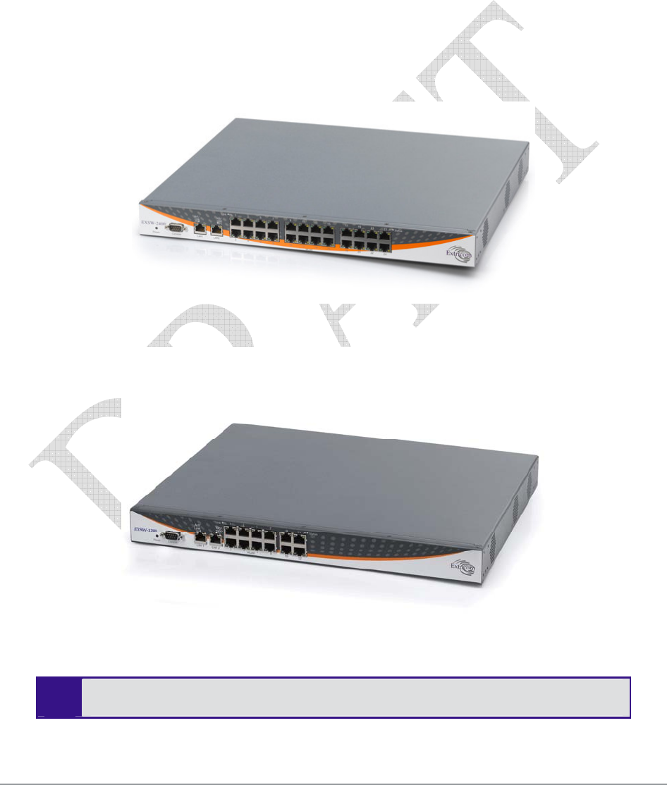
Overview of the Extricom Switches
The Extricom EXSW-800 the EXSW-1200 and the EXSW-2400 switches provide central control
and configuration of the WLAN. The switches implement the Interference-Free architecture in the
Extricom WLAN. The WLAN switches are connected to EXRP-20 or the EXRP-40 access points to
form Extricom WALN network.
The EXSW-800 switch can connect up to 8 EXRP-20 APs each with two 802.11a/b/g radios, to
provide two channel blankets.
The EXSW-1200 and the EXSW-2400 can connect to the EXRP-20 or the EXRP-40 APs, the
EXSW-1200 can connect to 12 while the EXSW-2400 switch can connect up to 24 APs. Each with
two or four 802.11a/b/g radios, to provide two or four channel blankets.
Figure 2. Extricom EXSW-2400 Switch
Figure 3 Extricom EXSW-1200 Switch
The Extricom EXSW-1200 is derived from the EXSW-2400, it is based on the same
Hardware and Software , however , it supports 12 instead of 24 WLAN ports

8 Introduction to the Extricom Wireless LAN System
Figure 4. Extricom EXSW-800 Switch
Configuring a switch and its associated set of APs is as simple as configuring a single traditional
AP, greatly reducing the effort required to deploy and maintain the WLAN.
The minimal configuration required for the switch is done via a dedicated secured Web interface.
The Extricom WLAN System User Guide 9
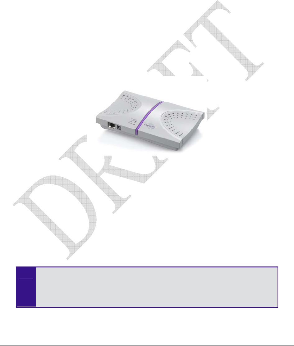
Overview of the Extricom Access Point
Extricom’s EXRP-20 and EXRP-40 UltraThin APs are high-bandwidth devices, containing standard
802.11 radio devices. The EXRP-20 contain two radio devices while the EXRP-40 contain four
radio devices
Since the APs have no software, they require no configuration. This makes them fully
interchangeable, enabling truly plug-and-play installation. If stolen, the APs do not pose a security
risk, since all encryption is performed in the switch.
With all intelligence residing in the WLAN switch, APs may be placed as close together as
necessary to provide high-quality, high-speed connectivity from all locations within the enterprise.
APs are connected to the Extricom WLAN Switch via standard Cat5e/6 cables. Since the APs are
powered by the standard 802.3af Power over Ethernet (PoE), only a single Cat5e/6 cable connection
is required to support two simultaneous radios.
Figure 5. Extricom EXRP-20 AP
Current software version on the WLAN switch only support two channel blankets, as
such when the EXRP-40 is connected, only two radio devices on this access point
will operate. Future versions will support full configuration
Extricom APs only function when they are directly connected to Extricom switches.
10 Introduction to the Extricom Wireless LAN System
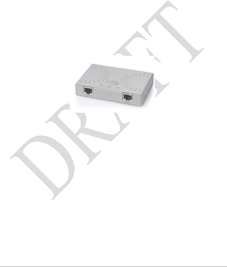
Overview of the Extricom Repeater
The EXRE-10 Power Over Ethernet (PoE) Range Extender is a unique product that doubles the
standard range of PoE, from the baseline 100 meters to a full 200 meters. It can be used both as a
standalone to extend the reach of PoE installations that are limited power source UL approved, and
as a complement to Extricom’s award-winning Interference-Free™ Wireless LAN (WLAN)
System. When used in WLAN implementations, the EXRE-10 enables Extricom UltraThin™
Access Points to be connected using standard Cat5e/6 cable up to 200 meters from the Extricom
WLAN Switch.
Continuing Extricom’s tradition of deployment simplicity, the EXRE-10 PoE Range Extender sits
in-line on the Ethernet cable and does not require an external power feed. The Range Extender
receives its power from the original PoE injector in the switch or from a PoE injector/power supply,
while it simultaneously injects PoE to the extended cable
Figure 6 Extricom EXRE-10 PoE Range Extender
The Extricom WLAN System User Guide 11
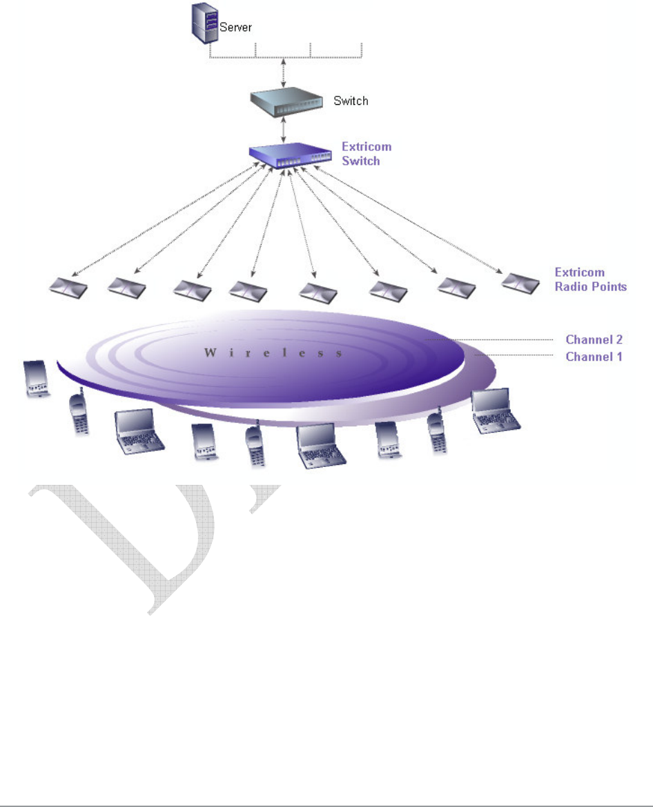
A Typical Extricom Wireless Network Topology
Extricom’s switch is connected to the wired LAN, and the APs spread throughout the enterprise.
Figure 7 displays a typical Extricom enterprise topology, consisting of an Extricom switch and
eight APs.
Figure 7. Typical Extricom Typology
Extricom uses standard WLAN protocols (IEEE 802.11). As a result, any 802.11a/b/g standard
wireless device can work seamlessly with the Extricom system.

The Extricom WLAN System User Guide 13
Chapter 2
Installing the Extricom WLAN System
This chapter provides instructions for unpacking and installing the Extricom WLAN system.
Unpacking the Extricom WLAN System
The Extricom WLAN system is shipped with the following:
One Extricom switch.
CD which contains The Extricom WLAN System User Guide and Release Notes.
APs (the number of APs is based on customer order and provided in separate boxes) are
shipped as part of the overall order.
Additional Equipment Needed
The following additional equipment is required for installing the Extricom WLAN system:
One CAT-5e/6 cable for each AP.
One CAT-5e/6 cable for connecting the WLAN switch uplink to the LAN switch.
Two stainless steel pan head 8x1-1/4" self-tapping Phillips screws for mounting each AP
(optional).
One power cable - For connecting power to the switch, use an AC power supply cord that
has a standard plug and a C-13 connector that conforms to the following minimal
requirements:
Approx. AWG: 16
Strand 31/32
Power Rating: 10 A
-
Use of a poorly grounded or ungrounded power cable may damage the switch.
14 Installing the Extricom WLAN System
Determining the Location of the Extricom Access
Points
Before installing the switch and access points, plan the placement of the APs. Before permanently
mounting the APs, it is recommended to test the network (using a laptop client) to identify potential
coverage holes. If such a problem exists, relocate an AP or add additional APs to resolve the
coverage hole.
The APs should be placed in a stable, secure location, such as on top of a closet or bookshelf, or
mounted on a wall.
The switch should be placed near the distribution point of the LAN line. This is usually in the
communications closet of your enterprise.
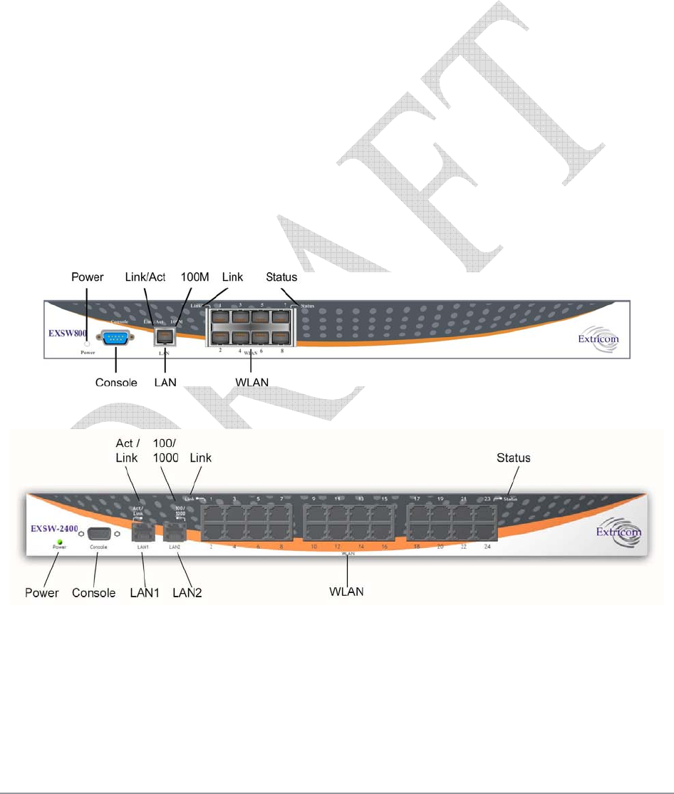
The Extricom EXSW-800/1200/2400 Switch
The Extricom EXSW-800 switch has 10 connectors and 4 LED types on the front panel (refer to
Figure 6).
The Extricom EXSW-2400 switch has 27 connectors and 4 LED types on the front panel (refer to
Figure 9).
Figure 8. Extricom EXSW-800 Switch
Figure 9. Extricom EXSW-2400 Switch
Table 1 describes the front panel and connectors of Extricom EXSW-800/2400 switches.

The Extricom WLAN System User Guide 15
Table 1. Extricom EXSW-800/1200/2400 Switch Connectors
Connectors Description
Console Serial connector – only to be used by, or as instructed by Extricom
personnel for troubleshooting, support, or maintenance. Can be
accessed using a Null modem cable.
EXSW-800
LAN
EXSW-
1200/2400
LAN1, LAN2
RJ-45 connectors – used to connect the switch to the wired LANs. On
EXSW-1200/2400 these connectors provide redundancy and load
sharing between them.
LAN2 is not currently active pending future development.
WLAN RJ-45 connectors – used to connect Extricom APs to the switch.
-
Do not connect any device other than Extricom APs to
the WLAN ports.
These ports provide 802.3AF PoE compatible power.
Maximum current: 270 mA, 48 volts.
Table 2 describes the front panel LEDs of Extricom EXSW-800/1200/2400 switches.
Table 2. Extricom EXSW-800/1200/2400 Switch LEDs
LEDs Color Description
Power Green On/off
LAN, LAN1, LAN2
Link/Act Green
On indicates connection to the LAN network
Blinking indicates activity in the LAN network connection
Off indicates no connection to the LAN network
EXSW-800
100M
Orange
On – 100Mbps full duplex
Off – 10Mbps
EXSW-
1200/2400
100/1000
Orange
On – 100Mbps full duplex
Blinking – 1000Mbps full duplex
1000Mbps is not currently active pending future
development.
WLAN
Link Green
On indicates connection to the WLAN AP
Blinking indicates activity over the connection to the WLAN
AP
Off indicates no connection to the WLAN AP
16 Installing the Extricom WLAN System
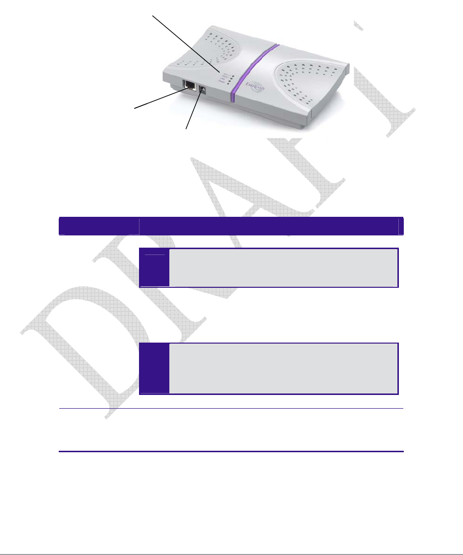
The Extricom Access Points
Extricom APs have two connectors located on the side of the device and four LEDs located on the
top of the device.
LEDs
WLAN Connector
Power Connection
LEDs
WLAN Connector
Power Connection
Figure 10. Extricom AP
Table 3 describes the Extricom Access Point connectors.
Table 3. Extricom AP Connectors
Connectors Description
Power
External power is not required for most
applications. Power is supplied through the
Ethernet (PoE).
In case of an external power requirement by the application,
use UL Listed LPS (Limited Power Source) or NEC Class
II adapter. Rating – Input: 90-240VAC 0.8A max. Output:
48VDC 0.56A max.
-
Due to regulatory requirements and pending
certification process for the power supply
connector - external power supply should not be
used.
WLAN RJ-45 connector – used to connect the Extricom AP to the
Extricom switch. Power is provided by the Extricom switch
to the AP when directly connected to it.

The Extricom WLAN System User Guide 17
Table 4. Extricom EXRP-20 AP LEDs
LEDs Color Description
Radio 1 Green 1st Radio is active
Red 1st Radio is malfunctioning
Off 1st Radio is off
Radio 2 Green 2nd Radio is active
Red 2nd Radio is malfunctioning
Off 2nd Radio is off
LAN Green (flashing) Connection to Extricom switch is active
Off Not active
Power Green On/Off
Table 5 Extricom EXRP-40 AP LEDs
LEDs Color Description
Radio 1 Green 1st Radio is active
Red 1st Radio is malfunctioning
Off 1st Radio is off
Radio 2 Green 2nd Radio is active
Red 2nd Radio is malfunctioning
Off 3rd Radio is off
Radio 3 Green 3rd Radio is active
Red 3rd Radio is malfunctioning
Off 3rd Radio is off
Radio 4 Green 4th Radio is active
Red 4th Radio is malfunctioning
Off 4th Radio is off
Radio 3 and 4 are not supported in this release
18 Installing the Extricom WLAN System
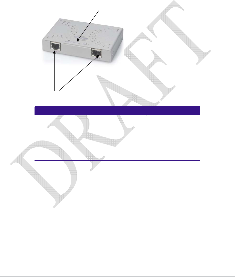
The Extricom Repeater
The Extricom EXRE-10 PoE Range Extender has two 10/100 Baest Ethernet interface with 803.3af
Power over Ethernet support.
LEDs Color Description
LAN-1 Green (flashing) Connection to Extricom switch is active
Off Not active
LAN-2 Green (flashing) Connection to AP is active
Off Not active
Power Green On/Off
LEDs
Ethernet

The Extricom WLAN System User Guide 19
Connecting the Switch and Access Points
Extricom’s switch is connected to the wired LAN and the APs that are located throughout the
enterprise.
To connect the switch and access points:
1. Using a CAT-5e/6 100/1000Mbps cable, connect the switch RJ-45 LAN connector (located on
the front panel of the switch, (refer to Figure 9) to the LAN switch.
2. Using a CAT-5e/6 cable, connect each AP (refer to Figure 9) to one of the switch’s RJ-45
WLAN connectors
3. Connect the power cable to the power connector located on the rear panel of the switch, and
plug the other end of the power cable into a power source.
4. Verify that the Power LEDs on both the switch and connected APs are green.
Additional APs can be connected/disconnected while the switch is active.
Mounting the Access Points (Optional)
Extricom APs can be mounted on the wall. To mount the APs, you will need two stainless steel pan
head 8x1-1/4" self-tapping Phillips screws.
To mount the Access Points:
1. Place the installation template (refer to Access Point Mounting Template on page 65) on the
wall where you want to mount the AP.
2. Mark the "Point for Drilling" locations on the wall.
3. Screw the two stainless steel pan head 8x1-1/4" self-tapping Phillips screws into the wall
leaving enough of the screws protruding to enable you to hook the AP over the screw.
4. Align the holes on the back of the Access Point with the screws and slip the AP into place.
Position the Access Point so that the connectors are on the bottom left corner of the
AP.
The Extricom WLAN System User Guide 21
Chapter 3
Configuring the Extricom WLAN
System
After connecting the switch and AP, configure the Extricom WLAN system through Extricom’s
web configuration GUI using a terminal or PC connected to the same LAN as the switch.
To access the Extricom web configuration pages:
1. In your Web browser, enter the following: https://<IP address of the switch>
where <IP address of the switch> is the IP address of the switch provided with your
purchase (for example, the URL should be https://1.2.3.4 if the IP address of the switch is
1.2.3.4).
If you did not receive a switch IP address with the switch, the factory default value
for the switch IP address is 192.168.1.254.
If you are using the default IP settings, do not place a router between the user PC and
the switch.
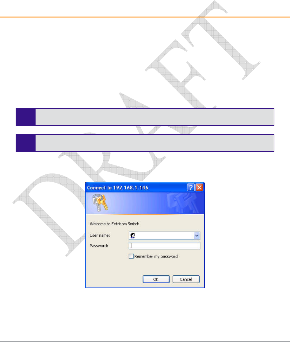
The Login page appears.
Figure 11. Login Page
2. Enter your user name and password (as provided by your system installer) and click OK. The
Summary page appears.
22 Configuring the Extricom WLAN System
If you did not receive a user name and password with your switch, use the following
factory default user name and password:
user name: admin
password: Switch1
The user name and password are case-sensitive.
Using the Extricom Web Configuration Pages
The Extricom Web configuration pages have three main areas:
The navigation tree.
The menu bar.
The work area.
Figure 12. Typical Web Configuration Page
Navigation
Tree
Menu Bar
Work area
The Extricom WLAN System User Guide 23
The navigation tree provides access to the following Extricom Web configuration pages:
LAN Configuration – used for configuring LAN parameters.
WLAN Configuration – used for configuring WLAN parameters.
SSID & Security – used for configuring SSID and security parameters and/or passwords and
external RADIUS servers and their timeouts for redundancy.
Advanced Features– used for configuring redundancy, SNMP and Rogue AP detection
parameters.
Centralized Configuration – used for configuration and control of remote switches from a
Master switch
Access Points – used for powering and activating/deactivating connected APs.
Utilities – used for viewing the system configuration file, or to restore system default
settings, upgrade the switch firmware, set the time and date manually or automatically, and
reboot the switch.
Password Management – used for changing system passwords
Reports & Events – used for viewing system events and performance reports.
Summary – provides a comprehensive summary of the system configuration.
About – provides basic information about the Extricom WLAN system firmware versions.
Alternatively, you can access the:
Summary page by clicking Summary in the menu bar.
About page by clicking About in the menu bar.
The work area displays the configuration pages selected in the navigation tree. Use this area to
configure the Extricom parameters.
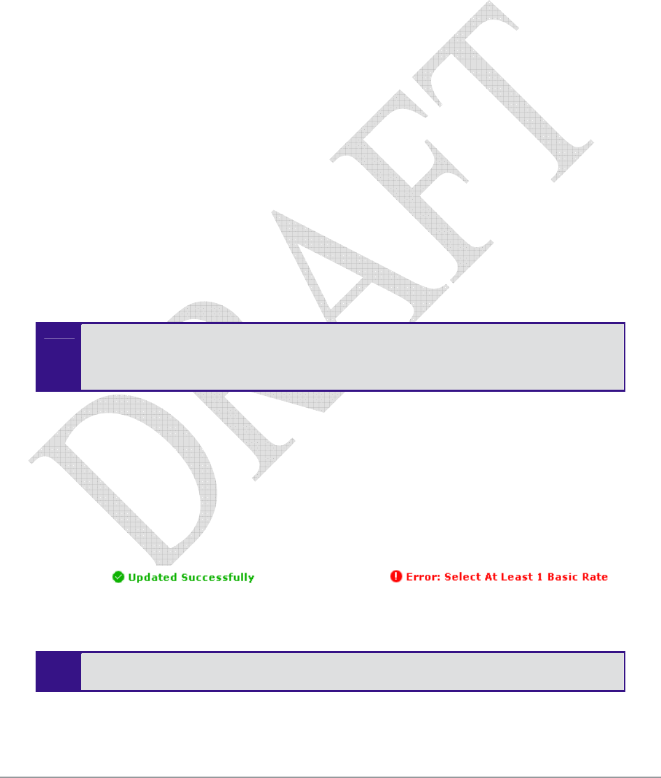
After changing the values of the configuration parameters on a web configuration page, you must
click Update to save the new configuration. An update status message appears at the top and
bottom of the page informing you if the update was successful (refer to Figure 13). If the update
was not successful, a description of the problem is displayed (refer to Figure 14).
Figure 13. Successful Update Message Figure 14. Unsuccessful Update Message
The new configuration only takes effect after rebooting the switch (refer to
Rebooting the Extricom Switch on page 46).
24 Configuring the Extricom WLAN System
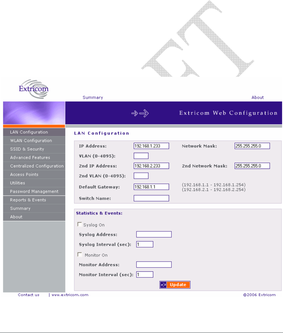
Configuring the LAN Parameters
In the LAN Configuration page, you can configure the following:
The LAN IP address and network mask, as well as a backup address and mask.
The LAN interface VLAN tag IDs.
The default gateway.
The address of the System Log and how often (if at all) the log is written to.
The address of the Monitor Log and how often (if at all) the log is written to.
.
To configure the LAN parameters:
1. Click LAN Configuration in the navigation tree. The LAN Configuration page appears (refer to
Figure 15).
Figure 15. LAN Configuration Page
The Extricom WLAN System User Guide 25
2. Configure the LAN parameters. Refer to Table 6 for a description of the LAN parameters.
Table 6. LAN Configuration Parameters
Field Description
IP Address Enter the main IP address of the Extricom Switch.
Network Mask Enter the network mask address.
VLAN VLAN tag ID for VLAN access to the switch
2nd IP Address Enter the backup IP address of the Extricom Switch.
2nd Network Mask Enter the backup network mask address.
2nd VLAN 2nd VLAN tag ID for VLAN access to the switch.
Default Gateway Enter the default gateway address.
The default gateway must be on the same
subnet as 1st or 2nd IP address.
Switch name A textual descriptor of the switch. Up to 32 characters.
Monitor On The Monitor Log is only relevant for a dedicated network
status monitoring tool that is not provided with the
switch. By default, this option should not be checked.
Check this option only if you are using the
Extricom dedicated network monitoring tool,
otherwise unnecessary data packets are sent
through the Ethernet.
Monitor Address Enter the address of the Monitor Log if using the
Extricom dedicated network monitoring tool.
Monitor Interval
(sec)
Specify how often information is sent to the Monitor
Log. If using the dedicated network status monitoring
tool, 1 second is the recommended interval.
Configure this parameter only if using the
dedicated network monitoring tool.
Syslog On Check the Syslog On option to record system information
in the System Log.
In most common operational scenarios, this
option should be unchecked (unless used for
troubleshooting).
Syslog Address Enter the IP address of the computer to send the System
Log.
26 Configuring the Extricom WLAN System
Field Description
Syslog Interval (sec) Specify how often information is sent to the System Log.
3600 seconds is the recommend default interval.
If you detect a problem, you can decrease
the Syslog Interval to receive updates more
frequently.
3. Click Update to save the configuration.
The new configuration only takes effect after rebooting or reconfiguring the switch
(refer to Rebooting the Extricom Switch on page 51).
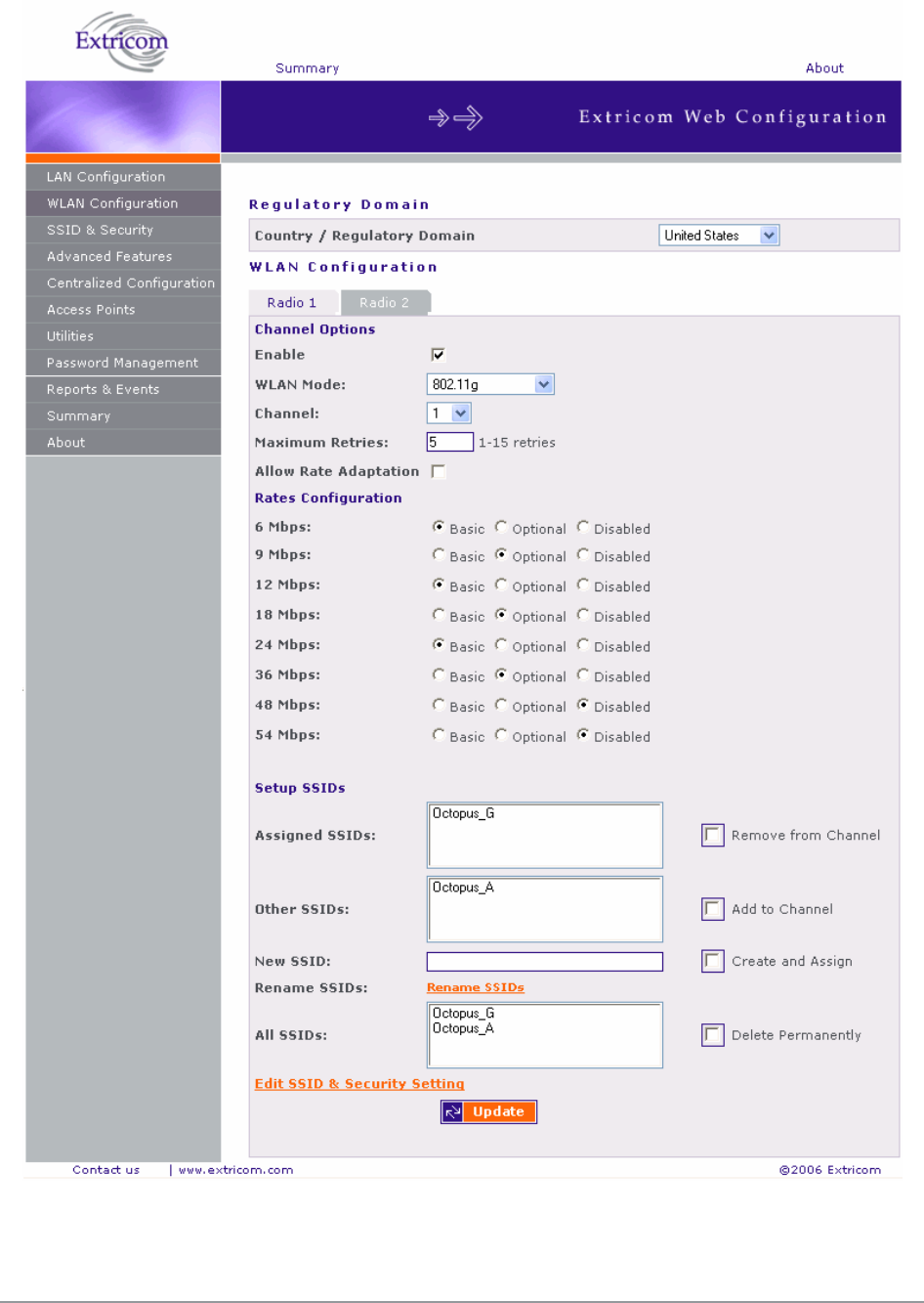
Configuring the WLAN Parameters
In the WLAN Configuration page, one can configure the following WLAN parameters for each
Radio (Radio 1 or Radio 2):
Channel options.
Data rates.
SSIDs.
There are up to 16 different SSIDs per channel.
Refer to Configuring SSIDs on page 30 for an explanation of the relationships
between radios, channels, SSIDs, and VLANs.
To configure WLAN parameters:
1. Click WLAN Configuration in the navigation tree. The WLAN Configuration page appears
(refer to Figure 16).
2. Select the “Country / Regulatory Domain” which meets your locale from the list.
3. Click the Radio tab for which you want to configure the WLAN parameters.
4. Configure the WLAN parameters. Refer to table 6 for a description of the WLAN parameters.
The Extricom WLAN System User Guide 27
Figure 16. WLAN Configuration Page

28 Configuring the Extricom WLAN System
Table 7. WLAN Configuration Parameters
Field Description
Channel Options
Enable Check this box if you want to enable the radio.
WLAN Mode Select the WLAN mode. Possible options are:
802.11a
802.11b
802.11g for pure mode
802.11b/g for mixed mode
Since the Extricom solution can support
two simultaneous channels in the same
frequency band, selecting the WLAN
mode enables the Extricom solution to
offer same band capability. This means
that both radios can be set to:
1. 802.11a & 802.11a
2. 802.11b & 802.11b
3. 802.11b & 802.11g
4. 802.11g & 802.11g
5. 802.11b/g & 802.11b/g
And any other combination.
Channel Select the channel. The options available are based
on the country and WLAN mode.
Maximum Retries Select the number of times to try to resend a packet
if the transmission of the packet fails.
Allow Rate
Adaptation
Check this box if you want to enable rate adaptation.
All enabled rates participate in the rate
adaptation..

The Extricom WLAN System User Guide 29
Field Description
Rates
Configuration
For each of the data rates listed, select whether the
rate is Basic, Optional, or Disabled.
When configuring the data rates, you should
consider the data rate capabilities of the wireless
devices in your enterprise.
Basic – The Basic data rates are usually the data
rates that the vast majority of your wireless
devices can support. Only wireless devices that
support all the Basic data rates will be connected
to the WLAN system. Therefore, it is
recommended that you configure a minimal
number of Basic data rates that the vast majority
or all your wireless devices can support. When
working in Mixed Mode, there should be at least
one Basic data rate from the 802.11b rates.
Optional – If you configure a data rate as
Optional, the network will provide that data rate
to wireless devices that can support it.
Disabled – Disabled data rates are not available
to wireless devices.
Since the Extricom WLAN system allows
for dense deployment of APs it is
recommended where applicable, to
disable low data rates. Not doing so could
possibly lead to an “edge user” effect, in
which a client reduces aggregate network
throughput by moving to the edge of the
coverage area.
Short Preamble: This option becomes available only when selecting
802.11b as the WLAN mode. In this case, mark the
checkbox to allow a short preamble.
Setup SSIDs
Assigned SSIDs Displays the list of SSIDs assigned to the channel.
Remove from
Channel
To remove an SSID from the channel, select an
SSID and check the Remove from Channel option.
The SSID is removed from the Assigned SSIDs list,
and appears on the Unassigned SSIDs list after
clicking Update.
In the Extricom WLAN system, a single
channel can support up to 16 different
SSIDs.

30 Configuring the Extricom WLAN System
Field Description
Unassigned SSIDs Displays the list of SSIDs not assigned to the
channel.
Add to Channel To add an unassigned SSID to the channel, select an
SSID from the Unassigned SSIDs list and check the
Add to Channel option. The selected SSID is
removed from the Unassigned SSIDs list and added
to the Assigned SSIDs list after clicking Update.
New SSID To create a new SSID and assign it to the selected
channel, enter a unique SSID name and check the
Create and Assign option. The new SSID is added to
the Assigned SSIDs list after clicking Update.
The character Space may be used in SSID
name.
Create and Assign Check to assign the new SSID. The new SSID is
added to the Assigned SSIDs list after clicking
Update.
All SSIDs Displays a list of all SSIDs configured for the
switch.
Delete Permanently To delete an SSID from the switch, select an SSID
from the All SSIDs list and check the Delete
Permanently option. The SSID is removed from any
list on which it appears after clicking Update.
5. Click Update to save the configuration.
The new configuration only takes affect after rebooting or reconfiguring the
Extricom Switch (refer to Rebooting the Extricom Switch on page 51).
6. To configure WLAN parameters for another radio, click the tab for that radio, configure the
WLAN parameters, and click Update to save the configuration.
7. To configure SSID and security settings, click Edit SSID & Security Setting. Refer to
Configuring SSIDs on page 30, and Configuring Security Definitions on page 35.
To configure SSID and security settings, you can also click SSID & Security in the
navigation tree.
Configuring SSIDs
An SSID (Service Set Identifier) is the name of the network. Wireless devices must connect to a
specific SSID which determines the pre-defined set of privileges, settings, and limitations (such as
security definitions, access privileges, VLAN assignments, etc.) of the network. Each channel can
support multiple SSIDs, thus creating “virtual” networks on the same channel.

The Extricom WLAN System User Guide 31
The following is the data structure used by the Extricom system:
Each radio is assigned one channel.
Each channel can support up to 16 different SSIDs.
Each SSID can be associated with a VLAN tag.
The same SSID name cannot be repeated for different channels.
Table 8 shows this data structure with an example of possible channel, SSID and VLAN tag
assignments.
Table 8. Data Structure Example
Access Point Channel SSID VLAN tag
Network1 1
Network2 2
… …
… …
Network15 15
First Radio 1
Network16 16
Network17 17
Network18 18
… …
… …
Network31 31
Second Radio 6
Network32 32
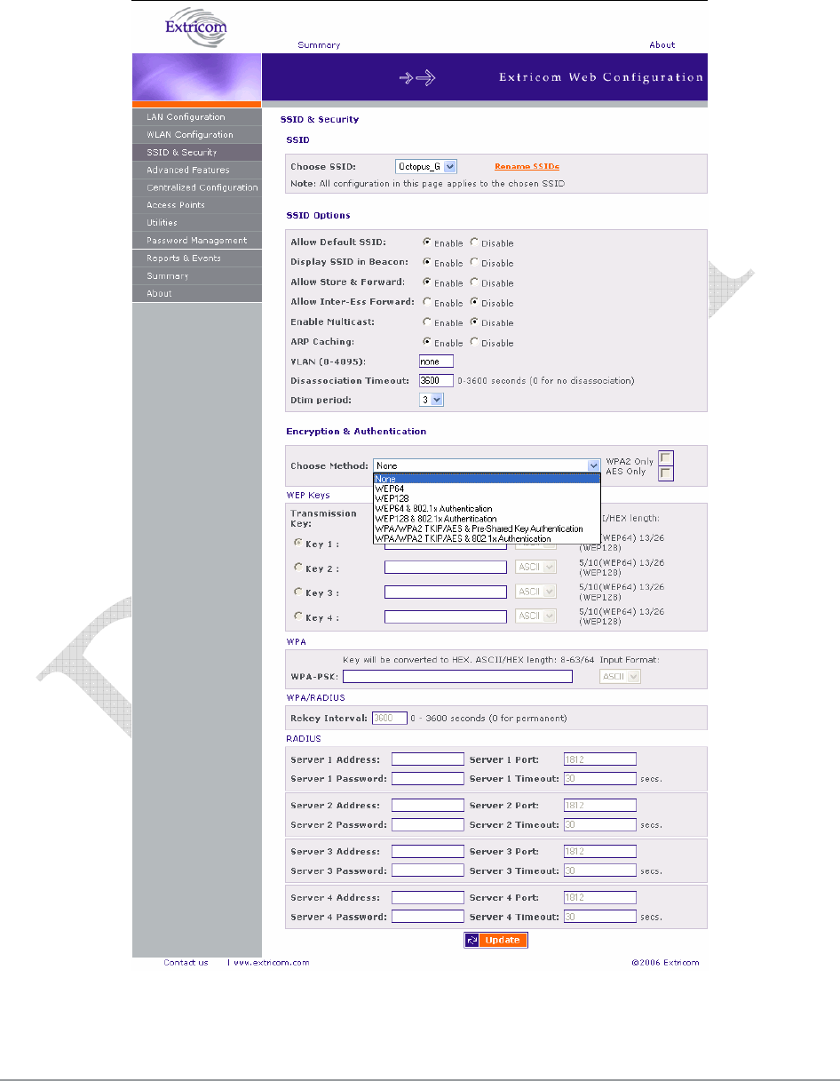
In the SSID & Security page, SSID Options section, the following SSID parameters can be
configured to:
Allow Default SSID.
Display SSID in Beacon.
Allow Store & Forward.
Allow Inter-Ess Store & Forward
Enable Multicast
ARP Caching
Assign a VLAN to the SSID.
Set a disassociation timeout.
Set DTIM period.
32 Configuring the Extricom WLAN System
To configure the SSID parameters:
1. Click SSID & Security in the navigation tree. The SSID & Security page appears (refer to
Figure 17).
Figure 17. SSID & Security Page

The Extricom WLAN System User Guide 33
2. Configure the SSID parameters. Refer to Table 9 for a description of the SSID parameters.
Table 9. SSID Parameters
Field Description
SSID
Choose SSID Select an SSID from the Choose SSID dropdown
list.
To add/remove SSIDs from this list, click WLAN
Configuration (refer to table 6).
SSID Options
Allow Default SSID If this option is enabled, a wireless device will be
allowed to connect even without requesting a
specific SSID (i.e., “default” or “any” SSID) to the
Extricom WLAN. If this option is disabled, then a
wireless device needs to connect to a specific SSID
in the Extricom WLAN.
Display SSID in
Beacon
This option provides an additional (though limited)
level of security. The AP sends out a beacon with
information about the network. If this option is
enabled, the SSID appears in the beacon. If disabled,
the SSID does not appear in the beacon.
Allow Store &
Forward
If this option is enabled, two wireless devices
connected to the Extricom WLAN with the same
SSID can communicate and transfer data to each
other without going through a router. Traffic
between wireless devices will not be forwarded to
the LAN switch.
If this option is disabled, all traffic goes through the
LAN switch. Wireless devices will not be able to
communicate without going through a router. This
could be used by IT managers to apply security
settings or various policies in the LAN network.
Disabling Allow Store & Forward disables
the Allow Inter Store & Forward option.

34 Configuring the Extricom WLAN System
Field Description
Allow Inter Store &
Forward
If this option is enabled, two wireless devices
connected to the Extricom WLAN with different
SSIDs will be able to communicate with each other
without going through a router. Traffic between
wireless devices will not be forwarded to the LAN
switch.
This option must be enabled on both SSIDs.
In order for wireless devices, associated to
different SSIDs, to be able to communicate
with each other, the SSIDs must be defined
on the same VLAN (or no VLAN at all).
If this option is disabled, all traffic goes through the
LAN switch. This could be used by IT managers to
apply security settings or various policies in the
LAN network.
Enable Multicast This option, when enabled, provides support of
multicast and broadcast packets for the selected
SSID. Multicast and/or broadcast packets shall be
transmitted from all APs.
ARP Caching This option, when enabled, provides an immediate
response to ARP requests directed towards WLAN
stations associated with the selected SSID. The
Switch answers on behalf of the WLAN stations.
VLAN Enter a VLAN tag to assign to the SSID. Assigning
a VLAN to an SSID enables you to control a
wireless devices’ privileges through the existing
wired network definitions.
Disassociation
Timeout
Enter the amount of time (in seconds) a wireless
device can remain inactive (no data sent to or from
the wireless device) before automatically
disconnecting from the network.
DTIM Period The period of time after which broadcast and
multicast packets are transmitted to mobile clients in
the Active Power Management mode.
Select the DTIM period for the selected SSID. This
is relevant for clients that want to utilize the power
management capability. The possible values are 1-5.
The default is 3.
A high DTIM value may cause these
clients to loose connection with the
network.
The remaining parameters in the SSID & Security page are described in Configuring
Security Definitions on page 30).
The Extricom WLAN System User Guide 35
3. Click Update to save the configuration.
The new configuration only takes affect after rebooting the switch (refer to
Rebooting the Extricom Switch on page 46).
Configuring Security Definitions
In the SSID & Security page Encryption & Authentication section (refer to Figure 17), the following
security definitions can be configured:
Type of encryption.
Type of authentication.
With some configurations, you can use encryption without authentication. However,
for a higher level of security, it is recommended to use both encryption and
authentication.
Extricom system eases the configuration of the SSID security parameters by
providing a list of available combinations of Encryption and Authentication protocols
Security definitions are configured for each SSID individually.
To configure the security definitions:
1. Click SSID & Security in the navigation tree. The SSID & Security page appears (refer to
Figure 17).
2. Select the SSID from the Choose SSID dropdown list for which you want to configure the
security definitions.
3. Configure the security definitions for the selected SSID. Refer to Table 10 for a description of
the Security parameters.

36 Configuring the Extricom WLAN System
Table 10. Security Definition Parameters
Field Description
Encryption & Authentication
Choose method Define the method of encryption and authentication.
A combination of encryption and authentication methods may be
selected from the options detailed in the drop-down list.
Encryption cipher
There are three types of encryption ciphers available:
WEP64 – Wired Equivalent Privacy (802.11 encryption
protocol). This is a very basic encryption level. (AKA WEP40)
WEP128 – This encryption is similar to WEP64, but the WEP
keys are longer. (AKA WEP104)
TKIP – Temporal Key Integrity Protocol. This is a more secure
and more advanced method of encryption as a part of the WPA
standard.
AES (CCMP) – Advanced Encryption Standard.(Cipher Block
Chaining Message Authentication Code Protocol) is currently
the most advanced and secured method of WiFi encryption and
is part of 802.11i (WPA2) standard.
Authentication method
Authentication is used to identify if a wireless device is authorized
to connect to the WLAN, and verifies the wireless device’s
identity. Authentication methods (such as specific EAP methods
available in the WPA/WPA2 (RADIUS) option) also verify that the
association process is secured. Authentication utilizing
WPA/WPA2 (RADIUS) can also support encryption key changes.
The following methods are available:
802.1x – if the cipher is WEP or WEP104
WPA/WPA2-PSK or WPA/WPA2 (RADIUS) – if the cipher is
TKIP or AES
Supported protocols: EAP, TLS, TTLS, PEAP, LEAP and MD5
When choosing the encryption cipher and authentication
methods, one should take into account wireless devices’
capabilities.
Any security combination (Encryption and Authentication) can be
selected by the user as a combination of the list and the check
boxes.
The Extricom system supports “WPA2 Mixed Mode”.
This mode permits the coexistence of WPA and WPA2
clients on the same SSID. WPA2 mixed mode allows
“Old” WLAN clients with “New” WLAN clients on
the same SSID during transition period.

The Extricom WLAN System User Guide 37
Field Description
WEP Keys The WEP Keys area is only enabled if the cipher selected in the
Choose Method field is WEP or WEP104. In the WEP Keys area,
you define the WEP Key that is used for encrypting or decrypting.
You can define all four WEP keys. For each key you define, select
the input format (ASCII or HEX) and enter the key according to
the following table:
Cipher ASCII HEX
WEP64
(or WEP64+802.1x)
5 characters 10 digits
WEP128
(or WEP128+802.1x)
13
characters
26 digits
Transmission Key Select the WEP64/WEP128 key to be used for transmitting the
data from the AP.
WPA The WPA area is only enabled if the cipher selected in the Choose
Method field is WPA/WPA2 TKIP/AES.
WPA-PSK If WPA/WPA2 with Pre-Shared key authentication is used, the
WPA-PSK field is enabled. In this case, select one of the
following input formats, and enter the corresponding key listed:
For ASCII, enter 8-63 characters.
For HEX, enter 64 digits.
WPA/RADIUS
Re-key Interval Enter the amount of time (in seconds) that elapses before the
Group Key is changed.
RADIUS Define the RADIUS servers parameters if:
The cipher is WEP64/WEP128, and the 802.1x authentication
method is selected.
The cipher is TKIP/AES, and the WPA/WPA2 (RADIUS)
authentication method is selected.
Server Address Enter the address of the RADIUS server.
Use Server # 1 if only one server is used. Use
consecutive servers if several servers are used.
Server Port Enter the RADIUS server port.
Server Password Enter the RADIUS server password.
Server Timeout Enter the time which the Extricom switch waits for the RADIUS
server response.

38 Configuring the Extricom WLAN System
Encryption and Authentication methods.
The “Choose Method” drop down list in “Encryption & Authentication” displays the following
items for user selection:
None
WEP64 (Open)
WEP128 (Open)
WEP64 & 802.1x Authentication
WEP128 & 802.1x Authentication
WPA/WPA2 TKIP/AES & Pre Shared Key Authentication
WPA/WPA2 TKIP/AES & 802.1x Authentication
When the “WPA2 Only” is checked, only Clients with WPA2 support are allowed access to the
WLAN.
When the “AES Only” is checked, only Clients with AES support are allowed access to the WLAN.
Cisco LEAP protocol (not CMIC & CKIP) is supported under “WEPxxx & 802.1x Authentication”.
Multiple RADIUS and RADIUS redundancy
RADIUS is a common authentication protocol utilized by the 802.1x security standard (often used
in wireless networks). Although RADIUS was not initially intended to be a wireless security
authentication method, it improves the WEP encryption key standard, in conjunction with other
security methods such as EAP-PEAP.
In an enterprise environment several RADIUS servers may be used for backup and also for serving
different geographical locations. Up to four different RADIUS servers can be defined for each
SSID. RADIUS redundancy is based on the assumption that the user database is identical in all
RADIUS servers and that users are listed in all servers with the same credentials.
Switch over from one RADIUS server to another takes place after consecutive failures of the server.
The order of priorities is 1 to 4.
4. Click Update to save the configuration.
The new configuration only takes affect after rebooting or reconfiguring the switch
(refer to Rebooting the Extricom Switch on page 51).
The Extricom WLAN System User Guide 39
Advanced Configuration of the Extricom WLAN
Architecture
The advanced configuration page of Extricom WLAN includes two tabs:
Advanced
Rogue
Advanced Tab
The Advanced tab includes the capability to configure the following:
Redundancy parameters.
SNMP parameters.
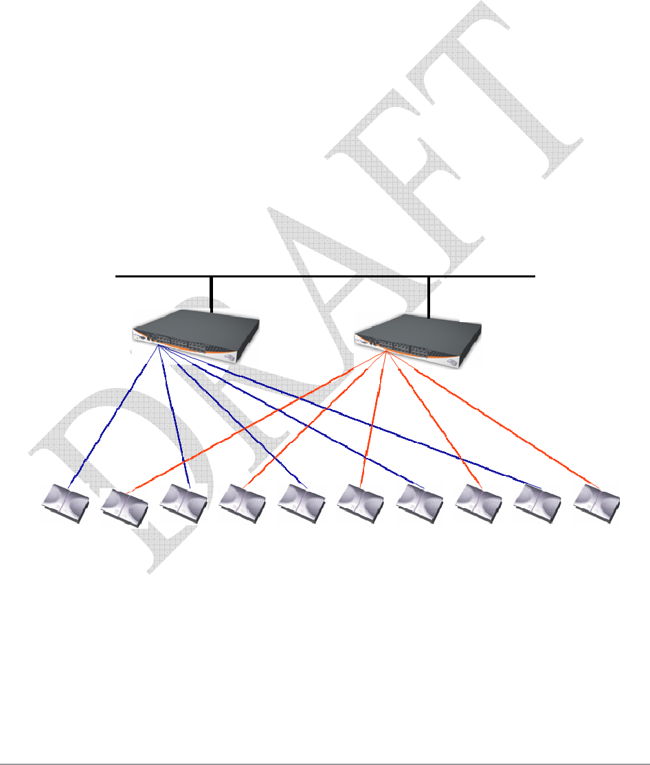
In redundancy mode, two identical switches (H/W and configuration) are installed with the same
number of connected APs.
One of the switches is configured as the Main switch, while the second is in Stand-by mode, and
can switch over as soon as the switch-over conditions are met.
Figure 18. Redundancy deployment
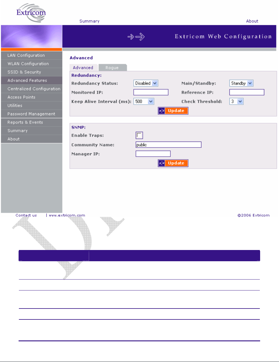
To configure the Advanced Features parameters:
1. Click Advanced Features in the navigation tree. The Advanced configuration page appears
(refer to Figure 19 ).
2. Select Advanced tab for configuring redundancy and/or SNMP parameters
3. Configure the redundancy, and SNMP parameters. Refer to Table 11 for a description of the
Advanced Features configuration information.
Main Stand-by
40 Configuring the Extricom WLAN System
4. Select Rogue tab for configuring Rogue AP detection and parameters (refer to Figure 20).
5. Configure Rogue AP parameters. Refer to table 11 for a description of the Rogue AP
configuration information
Figure 21 Advanced Features
Table 12. Advanced Configuration Tab
Field Description
Redundancy Status Enables designating pairs of switches, one as active and one as
standby.
Monitored IP The IP address of the other switch.
Reference IP The IP address of a reference network element. This is used to
test connectivity to the LAN.
Keep Alive Interval The interval in mSec between the Keep Alive packets.
Keep Alive Check
Threshold
The number of lost keep-alive packets before switching to the
stand-by switch.

The Extricom WLAN System User Guide 41
Field Description
SNMP
Enable Traps Check this option to enable SNMP traps.
Community name Enter the community name.
Manager IP Enter the manager’s IP address.
At present, the following Traps are sent from the Extricom switch to the device on the LAN running the
SNMP manager.
1. Client <Client MAC> has associated to <SSID> - This trap is sent after successful association
with the client MAC address and the SSID the client associated to.
2. Client <Client MAC> has disassociated from <SSID>. Reason: <Reason> - This trap is sent
after client disassociation/disconnection from an SSID. The reason code is an 802.11 reason code.
3. Key error! Client: <Client MAC> - SSID: <SSID> - Cipher suite: <Cipher> - This trap is sent in
case of any key error during four-way handshake (MIC error) or as a result of any key error when
receiving data from client..
4. New Rogue Detected <BSSID><Port><Radio><Channel><RSSI> - This trap is sent when a
new Rogue AP is detected. The trap includes the AP’s BSSID, the switch port which detected the
Rogue AP, the channel of the Rogue AP and the Rogue AP signal level (RSSI).
5. Rogue Updated <BSSID><Port><Radio><Channel><RSSI> - This trap is sent when an existing
previously detected Rogue AP is re-detected with change in one of its parameters. The trap
includes the AP’s BSSID, the switch port which detected the Rogue AP, the channel of the Rogue
AP and the Rogue AP signal level (RSSI).
6. Rogue Removed <BSSID><Port><Radio><Channel><RSSI> - This trap is sent when a new
Rogue AP is detected. The trap includes the AP’s BSSID, the switch port which detected the
Rogue AP, the channel of the Rogue AP and the Rogue AP signal level (RSSI).
7. RADIUS Timeout <ESSID><# of timeouts> - This trap is sent when the RADIUS timeout had
elapsed and includes the ESSID and the number of timeouts that occurred.
8. RADIUS Redundancy Selection Changed <ESSID><#of RADIUS>to<# of RADIUS> - This
trap is sent when the RADIUS selection has been changed from one server to another, and
includes the ESSID, the number of the previous server and the number of the new server.
9. No RADIUS <ESSID> - This trap is sent when the last RADIUS server failed and includes the
ESSID.
10. Configured and connected APs of channel [<channel number>] - This trap provides a summary
of all APs and their status. This trap is typically sent after an event of AP removal or connection
from/to the switch.
11. AP <ap number in hex base> has been connected - This trap is typically sent after an event of
connecting an AP to the switch.
12. AP <ap number in hex base> has been disconnected - This trap is typically sent after an event of
disconnecting an AP from the switch.
13. Reference Host is up – This trap is sent when the Reference host is up and active. Sent by the
Main switch.
14. Reference Host is down - This trap is sent when the Reference host is down. Sent by the Main
Switch.
15. Standby Switch is up - This trap is sent when the Standby Switch is up & active.
16. Standby Switch is down - This trap is sent when the Standby Switch is down.
17. Inactive - Reference Host is down - This trap is sent when the Reference host is down, and hence
the Main switch becomes inactive.

42 Configuring the Extricom WLAN System
18. Inactive Standby Switch - Main Switch is up - This trap is sent when the Main Switch becomes
active again and hence the Standby Switch becomes inactive (Switch over).
19. Main Switch is active again - This trap is sent when the Main Switch changes status from inactive
to active and regains the Main switch status.
20. Failure detected in Main Switch - Switching Over. - This trap is sent when the Main Switch is
about to go down and the Standby Switch is becoming Active.
Rogue Tab
A “Rogue” AP is an AP which is connected to an organization’s wired LAN without proper authorization.
Such an AP represents a security hazard since the organization cannot control that AP’s over-the-air
security measures.
Rogue APs pose threats to the enterprise. These threats vary and may include any of the following:
• WEP keys cracking.
• Password hijacking.
• IP and MAC spoofing.
• Channel jamming.
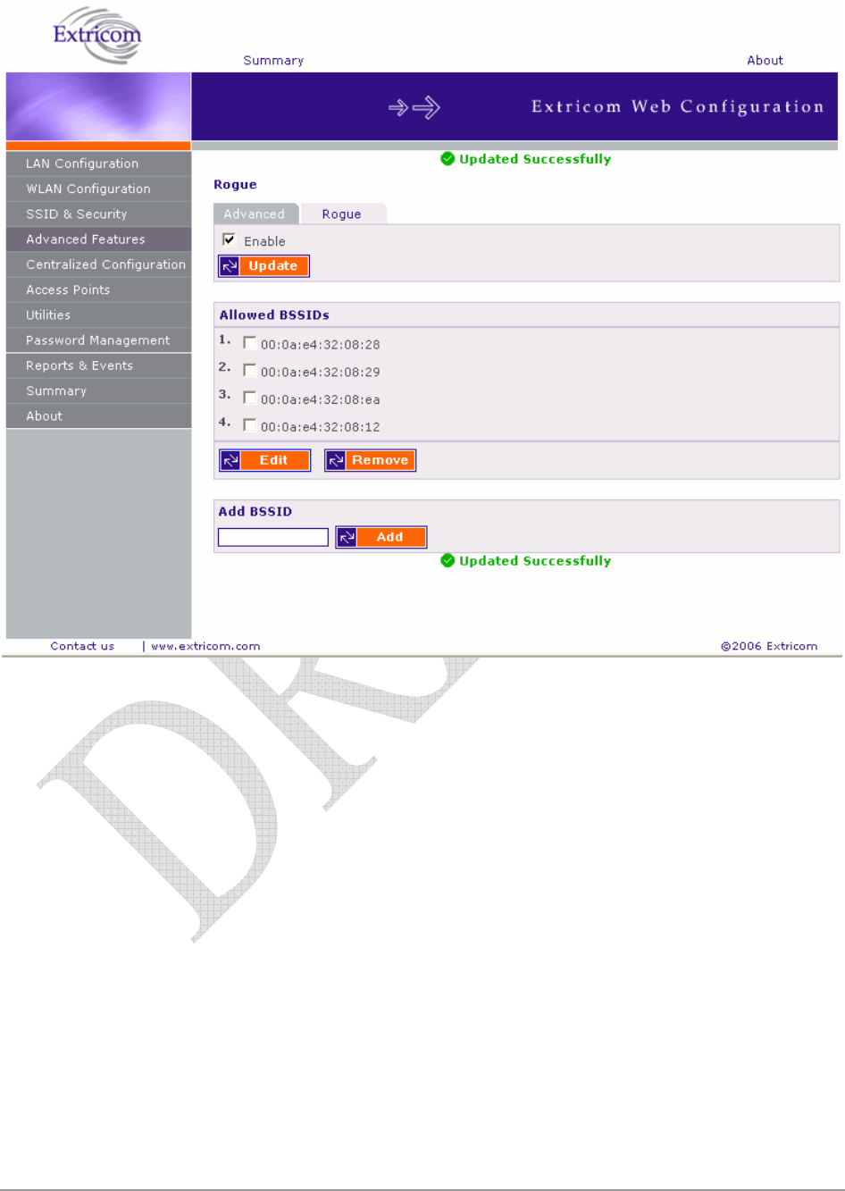
To configure Rogue AP detection parameters refer to Table 13: Rogue AP Tab and Figure 22
Table 13: Rogue AP Tab
Field Description
Enable Enables Rogue AP detection function
When Rogue AP detection is enabled the 2nd
radio is not used for service.
Allowed BSSIDs
Displays a list of authorized APs (White List)
Remove Removes checked BSSIDs from the white list.
Edit Provides capability of editing the white list
Add BSSID
Add Adds the BSSID in the text box to the white list. BSSIDs may
be added from events log.
The Extricom WLAN System User Guide 43
Figure 22: Rogue AP configuration.
44 Configuring the Extricom WLAN System
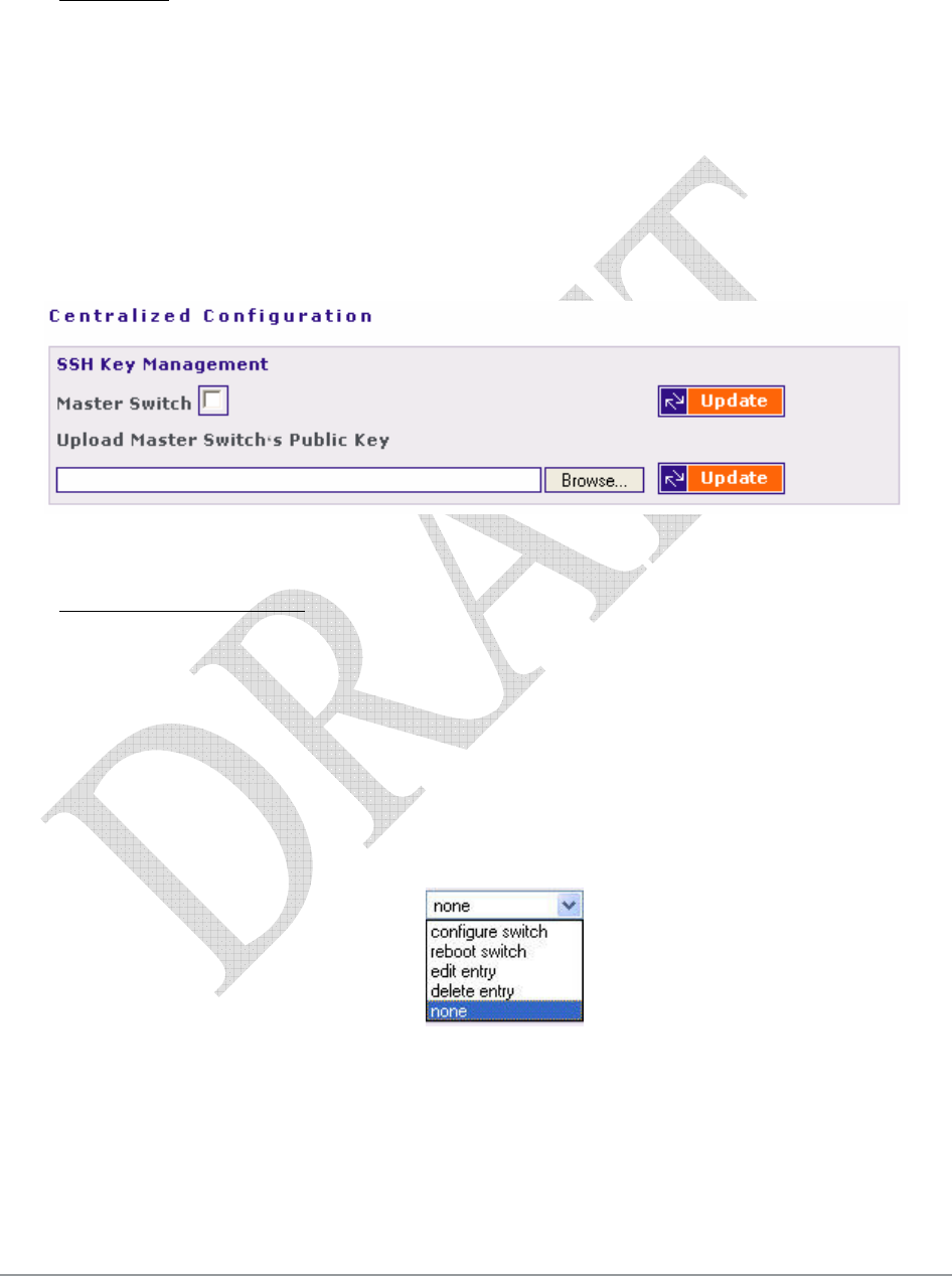
Centralized Configuration Settings
Centralized Configuration allows managing a group of identical Extricom switches (slaves) from
one single master switch. The user should decide which switch will act as master. Extricom
Switches have a built-in mechanism to discover the presence of other switches. In addition, the user
is given the ability to manually configure the entries in the table of switches.
Configuration changes on the master switch are propagated to the slave switches via a secured
mechanism. For this authentication scheme to work, the slave switches need to obtain a copy of the
master's public key prior to the centralized configuration. This is done in the initial phase of the
switch’s configuration by first retrieving the master's public key and then uploading it to the
designated slave switches.
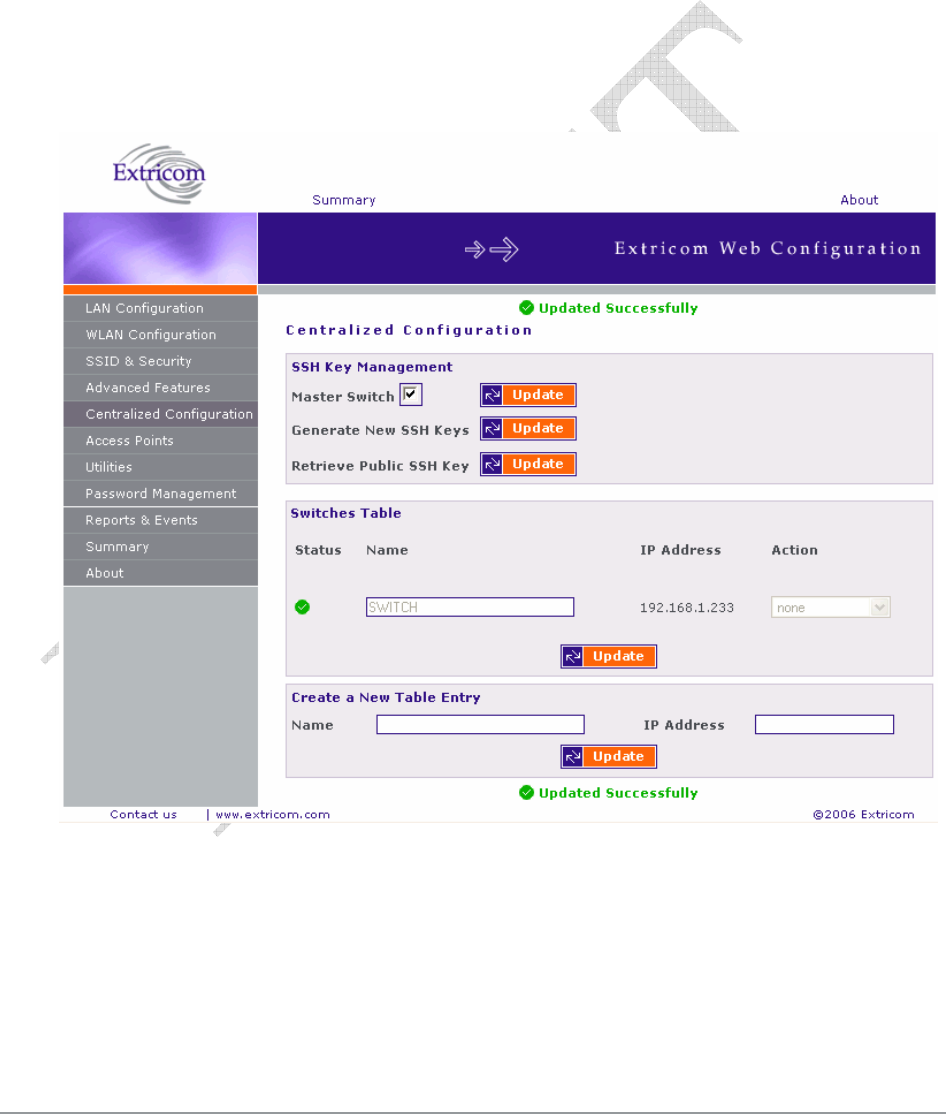
Figure 23. Central Configuration Page
The Extricom WLAN System User Guide 45
To configure Centralized Configuration parameters:
Initial Setup
1. Configure the LAN settings on the master switch
2. Generate an SSH key pair on the master switch. This is done by clicking on the Update
button next to the generate New SSH Keys.
3. Retrieve the SSH public key from the master switch and save it in a file on your PC.
4. Manually configure each of the slave switches’ LAN settings, and continue by uploading
the previously saved master's public key on every slave you wish to manage. This allows
the slave switch to be configured only by the master switch which generated the public key.
Figure 24. Central Configuration Page
Slave Switch Configuration
1. On the master switch, open the Centralized Configuration web page and click on the
Update button in the Switches Table section. This will retrieve and generate the slave
switches’ information and all the relevant dialog boxes will be filled with data.
2. Slave switches can be added to the switches table by creating a new entry. Simply enter the
new switch name and its IP address, and continue by clicking on the Update button.
3. Configure a slave switch, i.e. Copy the configuration file of the master with appropriate
changes to the slave.
Figure 25. Action options
4. Reboot the slave switches.
46 Configuring the Extricom WLAN System
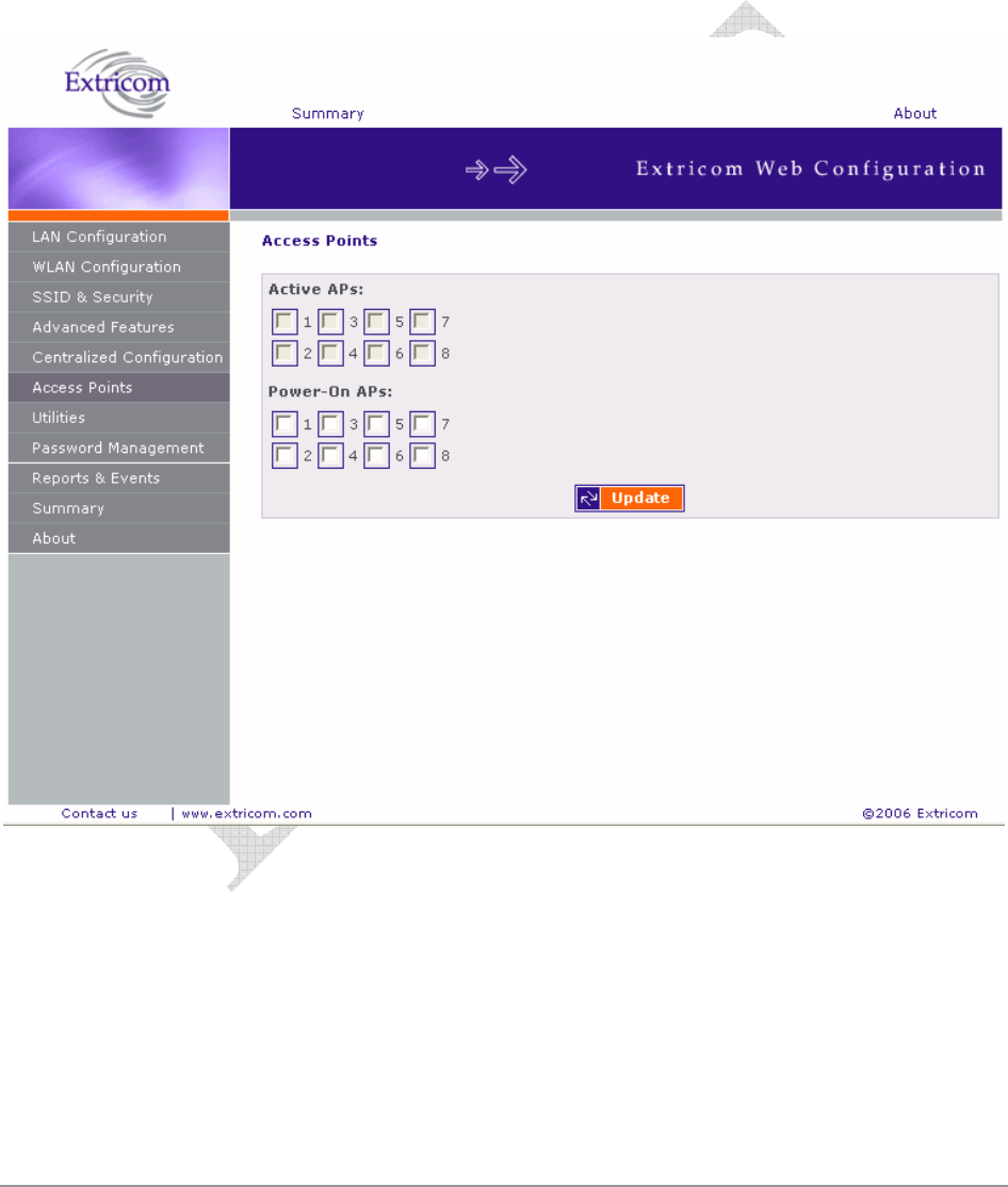
Access Points Powering
The only configuration required for APs in the Extricom WLAN architecture is activation or
deactivation of specified AP ports..
To access the Access Points page:
Click on the Access Points in the navigation tree. The APs configuration page appears
(refer to Figure 26).
Figure 26. APs Configuration Page
To configure APs:
Configure the APs and click Update. Refer to Table 14 for a description of the APs
configuration information.

The Extricom WLAN System User Guide 47
Table 14. AP Configuration Page
Field Description
Active APs Checked boxes indicate ports with attached and configured APs.
If a port is “powered” but not “active”, the AP is
malfunctioning. This field is read-only.
Powered APs Checked boxes indicate ports with attached and powered-on
APs. Un-checking a box will turn off the power on the AP. The
box must be re-checked to enable the port.
You do not need to reboot the switch for changes in AP configuration to take effect.
(The Access Points page of the EXSW-2400 displays 24 check boxes.)

48 Configuring the Extricom WLAN System
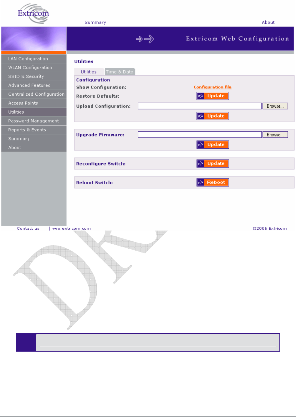
Configuration of the Extricom WLAN Architecture
Utilities
The utilities page includes two tabs and serves the following function:
Viewing the System Configuration File.
Uploading a new Configuration File (replace existing).
Upgrading the Extricom Firmware.
Reconfiguring the Extricom system
Rebooting the Extricom switch.
Setting the Time and Date (separate tab).
To access the Utilities configuration pages:
Click Utilities in the navigation tree. The Utilities configuration page appears (refer to
Figure 27).
The Extricom WLAN System User Guide 49
Figure 27. Utilities Configuration Page
Viewing the System Configuration File
The system configuration file contains all of the parameters that are configurable through the
configuration utility.
To view the system configuration:
1. In the Configuration section of the Utilities configuration page, click Configuration file. The
system configuration file appears in your Web browser.
2. Review the configuration in the XML file.
To return to the Extricom web configuration pages, click Back in your Web browser.
Configuration File Backup
You can create a backup file of the current configuration to upload in the future. This is an optional
procedure.

50 Configuring the Extricom WLAN System
To back up a configuration file:
1. In the Show Configuration section of the Utilities page, right-click Configuration file and select
Save Target As. The File Download dialog box opens, and then the Save As dialog box opens.
2. Select the location in which to save the configuration file and click Save. The configuration file
will be saved to the selected location.
Uploading a New Configuration File
A previously saved configuration file can be uploaded (e.g., a file saved for backup purposes).
To upload a new configuration file:
1. Backup the current XML configuration.
2. In the Upload Configuration section of the Utilities configuration page, click Browse and
browse to the location of the configuration file that you want to upload. The file’s path appears
in the Upload Configuration field.
3. Click Update to update the configuration.
4. Click Reboot at the bottom of the page to reboot the switch.
Make sure that you are uploading a valid configuration file.
Restoring System Defaults
Restores the switch to its default configuration.
To restore system defaults:
In the Utilities page, Configuration section Restore Defaults, click Update. The switch’s
defaults are restored.
Upgrading the Extricom Firmware
Extricom firmware can be easily upgraded using Upgrade Firmware.
To upgrade the Extricom firmware:
1. Download the upgrade to your computer from the CD supplied with your purchase.
or
Obtain an upgrade file from the Extricom’s website, http://www.extricom.com. Click the
Partners link on the menu bar at the top of the Extricom home page and log in using your
username and password.
2. Create a backup of the XML file that contains the current configuration.
3. In the Upgrade Firmware section of the Utilities configuration page, click Browse and browse
to the location of the upgraded firmware. The file’s path appears in the Upgrade Firmware field.

The Extricom WLAN System User Guide 51
4. Click Update to upgrade the firmware.
5. Reboot the switch (refer to Rebooting the Extricom Switch on page 46).
The firmware upgrade file is GNU zipped (gzip). Some Internet browsers are
configured to automatically unzip files when downloading. Verify that this option is
disabled so that the upgrade file remains zipped after downloading.
Rebooting the Extricom Switch
You must reboot the switch to activate any changes you make to the switch configuration.
To reboot the Extricom switch:
1. In the Reboot Switch section of the Utilities configuration page, click Reboot.
2. A new screen opens, prompting you “Are you sure you want to reboot?”.
3. Click Reboot to reboot.
Reconfigure Switch - Smart Configuration
Not every change in the Extricom switch’s configuration requires system reboot. Some parameters
can be changed and will take effect immediately. This button checks whether a full reboot is
required. In case reboot is not required, the update will take effect immediately.
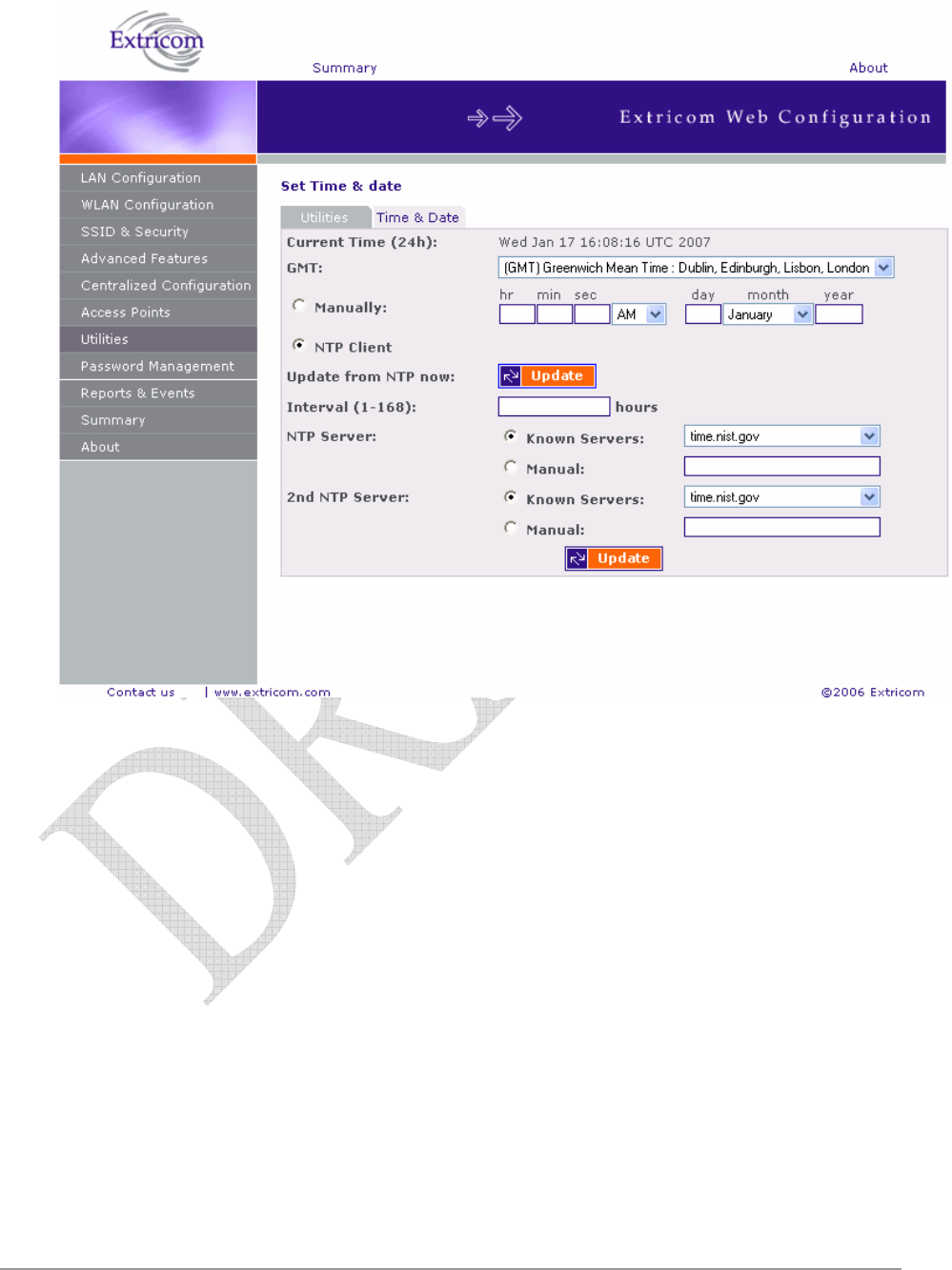
Setting the Time and Date
Extricom system supports two ways of setting Date and Time (refer to Figure 28)
To manually set the time and date on your Extricom Switch:
1. In the Set Time & Date tab of the Utilities configuration page, select Manually.
2. Enter the time and date in the format hh:mm:ss dd-mm-yy.
3. Click Update to save the configuration.
To set the time and date on your Extricom Switch using NTP protocol:
1. In the Set Time & Date section of the Utilities configuration page, enter the time and date in the
format hh:mm:ss dd-mm-yy.
2. Click Update to save the configuration.
52 Configuring the Extricom WLAN System
Figure 29. Setting Date and Time
The Extricom WLAN System User Guide 53
Setting Passwords in the Extricom Switch
Passwords are set according to user levels. Refer to Table 15 for a description of the user access
levels and their default passwords.
Table 15. Default Passwords
User Access
Level
Privileges Default
Password
admin Accessing the Web configuration. Switch1
The ‘operator’ and ‘root’ passwords are used when accessing the switch for
maintenance and service purposes. Changing these passwords should be performed
only by an Engineer authorized by Extricom.
!
For security purposes, it is important that all the passwords (including operator
and root passwords) be changed from the default values when the switch is first
installed, as well as periodically updated.
!
Record all passwords and store them in a safe location.
To set and change a password for the Extricom switch:
1. Click Password Management in the navigation tree to open the Password Management page.
2. Enter the user access level whose password you want to change.
3. Enter the current password.
4. Enter the new password.
5. Re-type the new password.
Viewing Reports and Events Log
The Reports & Events page provides performance reports and list of events.
To view Reports & Events:
1. Click Reports & Events in the navigation tree.
2. Select Reports tab to view True Reuse performance. The screen is updated every second.
3. Select Events tab to view events. Hit refresh in order to see new events.
54 Configuring the Extricom WLAN System
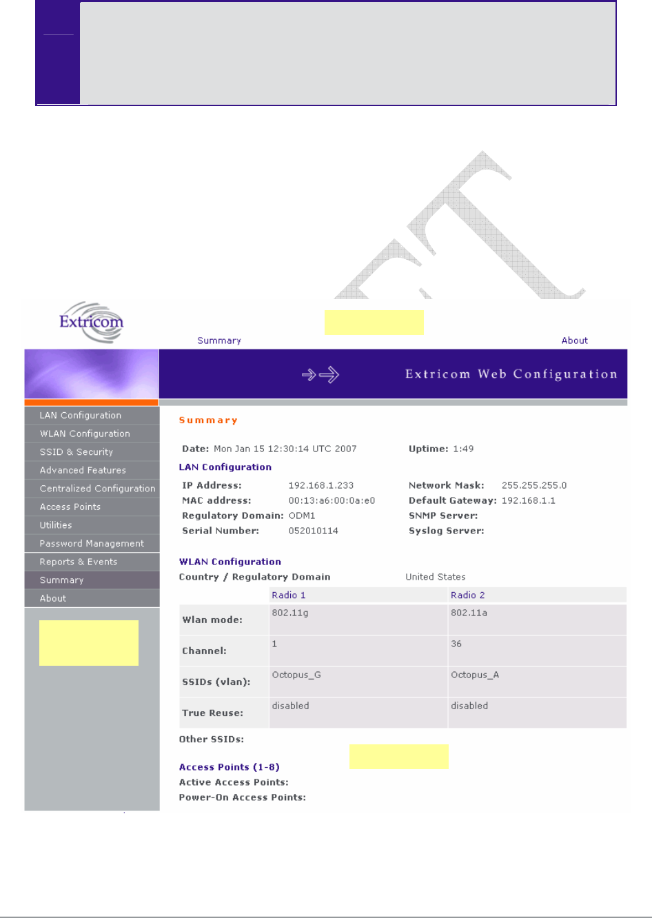
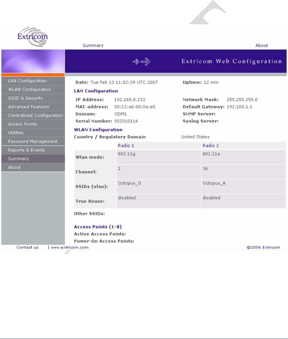
Viewing a Summary of the Updated Configuration
The Summary page provides a summary of the current configuration.
To view a summary of the updated configuration:
4. Click Summary in the navigation tree.
or
Click Summary in the menu bar.
The Summary page appears (refer to Figure 30).
Figure 30. Summary Page
Refer to Table 16 for a description of the summary information.

The Extricom WLAN System User Guide 55
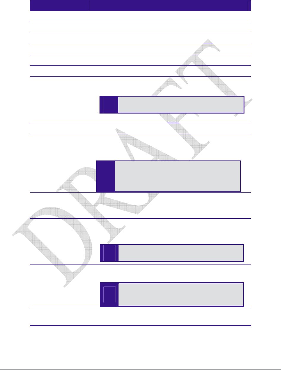
Table 16. Summary Page
Field Description
Date Displays the date and time the summary was created.
Uptime Displays the amount of time the switch has been active.
LAN Configuration
IP Address Displays the IP address of the switch.
MAC address Displays the base MAC address of the switch near the MAC address.
Regulatory
Domain
Displays the regulatory domain name currently in use by the switch.
Network Mask Displays the network mask.
Default Gateway Displays the default gateway IP address.
SNMP Server Displays the IP address of the SNMP server
Syslog Server Displays the IP address of the syslog server.
WLAN Configuration
Radio 1 Radio 2
Wlan mode
Displays the WLAN mode for
Radio 1
(802.11a, 802.11b, or 802.11g).
Displays the WLAN mode for
Radio 2
(802.11a, 802.11b, or 802.11g).
Channel Displays the channel for Radio 1. Displays the channel for Radio 2.
SSIDs (vlan)
Displays the SSIDs and their
related VLANs, defined and
assigned to Radio 1.
Displays the SSIDs and their
related VLANs, defined and
assigned to Radio 2.
True Reuse Displays TrueReuse status
Other SSIDs Displays other SSIDs that are defined but are not assigned to a
specific Radio.
Access Points (1-8/24)
Active Access
Points
List of the active APs.
Power-On
Access Points
List of APs powered via Power over Ethernet.

56 Configuring the Extricom WLAN System
Viewing Extricom Information
Information about firmware versions currently installed in the Extricom Wireless LAN system can
be viewed in the About page.
To view Extricom information:
Click About in the navigation tree.
or
Click About in the menu bar.
The About page appears.

The Extricom WLAN System User Guide 57
Chapter 4
Troubleshooting
Table 17 lists possible problems you may encounter with your WLAN and provides possible
solutions. If after attempting the solutions you are still experiencing difficulties, contact Extricom
customer support.
Table 17. Troubleshooting
Problem Solution
The AP Power LED
is not lit.
Verify that the AP Ethernet cable is connected to the switch and to
the AP. The APs get PoE from the switch.
Verify that the AP is not turned off in the Access Points Web
configuration page (refer to page 57).
A wireless device
can’t associate a
specific SSID
Verify that the wireless device supports the same 802.11 standard
as configured for the SSID (802.11/a/b/g).
Verify that the wireless device is set to connect to the specific
SSID.
Verify that the wireless device supports the security standard used
by the SSID, e.g., WEP.
Verify that the security settings are configured to use the same
authentication method.
If the Radius Server is used, verify that the wireless device is
registered and has the necessary authorization.
Cannot connect to
the Extricom web
configuration pages
Verify that the switch is connected to the LAN.
Verify that the correct IP address is used.
Low data rates
Verify that the switch was not mistakenly configured to use low
data rates.
Verify that there is no additional cause of interference (e.g., an
additional WLAN network in the same proximity using the same
frequencies as the Extricom WLAN, or that there are no cordless
phones using the same frequencies, or microwave oven
interference).

58 Troubleshooting
Problem Solution
Wireless devices
disconnect in a
specific location
Verify that there is no additional cause of interference (e.g., an
additional WLAN network in the same proximity using the same
frequencies as the Extricom WLAN, or that there are no cordless
phones using the same frequencies, or microwave oven
interference).
Add an additional AP to cover the area. Plug another AP into the
switch, or relocate an existing Access Point.
Cannot access the
switch’s Web
configuration GUI
Verify that the workstation on which the Web browser is running is
connected to the same LAN as the switch.
Verify that the URL entered for the switch begins with https.
The Extricom WLAN System User Guide 59
Appendix A
Specifications
Extricom Switch Specifications
Standards
WLAN IEEE 802.11a, 5GHz
IEEE 802.11b, 2.4GHz (short/long preamble support)
IEEE 802.11g, 2.4GHz (pure mode)
IEEE 802.11b/g, 2.4GHz (mixed mode)
Ethernet IEEE 802.3x, full/half duplex
IEEE 802.1q, VLAN tagging
Interfaces
APs
EXSW-2400 – 24x 100BaseT Ethernet with IEEE 802.3af PoE
(out of band)
EXSW-1200 – 12x 100BaseT Ethernet with IEEE 802.3af PoE
(out of band)
EXSW-800 – 8x 100BaseT Ethernet with IEEE 802.3af PoE
(out of band)
Wired LAN
EXSW-1200/2400 – 2x 1000/100BaseT Ethernet
EXSW-800 – 1x 100/10BaseT Ethernet
LAN2 and 1000Mbps are not currently active
pending future development.
Wireless Performance
Channels Up to 2 simultaneous WLAN channels
Capacity Up to 108Mbps Aggregate WLAN connection-rate (2 channel
blankets, each with 54 Mbps)
Inter-AP handoff 0 ms intra-switch
Management
User Interface Secure Web-based Graphical User Interface (GUI)
SNMP Traps, using SNMP Version 2c
Logging Remote and local SYSLOG

60 Specifications
Upgrades Firmware upgrade through Web from anywhere in the LAN.
Security
Encryption WEP-64
WEP-128
WPA-TKIP/AES (CCMP)
WPA2-TKIP/AES (CCMP)
Authentication 802.1x (RADIUS)
WPA/WPA2 pre-shared key
MAC Address-based ACL
EAP, TLS, TTLS, LEAP, PEAP, MD5
SSID & VLAN
SSID 16 SSIDs per channel
VLANs 4095 Ethernet VLANs
SSID to VLAN mapping
Regulations Approval
Safety UL 60950-1
EN 60950-1
IEC 60950-1
ANATEL Resolution 237
EMC FCC Part 15 Class B
EN 300386 Part B
VCCI Technical Requirements, V-3/2001.04
ANATEL Resolution 238
Physical Properties
Installation options Rackmount (19" 1U)
Desktop
LEDs Power
LAN Activity
WLAN Port Activity
Power PoE (IEEE 802.3af): 15W
PoE to WLAN ports: 15W for each port
Environmental
Operational Temperature: 0°C to 45°C (32°F to 122°F)
Humidity: 0% to 90%, non-condensing
Storage Temperature: - 20°C to +70°C (-49°F to 185°F)
Humidity: 0% to 90%, non-condensing

The Extricom WLAN System User Guide 61
Extricom Access Point Specifications
WLAN Standards
IEEE 802.11a, 5GHz
IEEE 802.11b, 2.4GHz (short/long preamble support)
IEEE 802.11g, 2.4GHz (pure mode)
IEEE 802.11b/g, 2.4GHz (mixed mode)
Spectrum
Number of simultaneous channels Up to two (four in EXRP-40)
802.11a 5.15-5.25 GHz
5.25-5.35 GHz
5.505-5.725 GHz
5.725-5.850 GHz
Available channels limited by local regulation
802.11b 2.400-2.497 GHz
Available channels limited by local regulation
802.11g 2.400-2.483 GHz
Available channels limited by local regulation
Transmission Power
802.11a Max: 17 dBm (limited by local regulation)
802.11b Max: 17 dBm
802.11g Max: 15 dBm
Supported Rates
802.11a 6, 9, 12, 18, 24, 36, 48 and 54 Mbps
802.11g 6, 9, 12, 18, 24, 36, 48 and 54 Mbps
802.11b 1, 2, 5.5, and 11 Mbps

62 Specifications
Receive Sensitivity
802.11a: 6 Mbps: -88 dBm
9 Mbps: -87 dBm
12 Mbps: -86 dBm
18 Mbps: -84 dBm
24 Mbps: -81 dBm
36 Mbps: -77 dBm
48 Mbps: -73 dBm
54 Mbps: -69 dBm
802.11b/g 1 Mbps: -91 dBm
2 Mbps: -88 dBm
5.5 Mbps: -87 dBm
11 Mbps: -85 dBm
6 Mbps: -89 dBm
9 Mbps: -88 dBm
12 Mbps: -87 dBm
18 Mbps: -85 dBm
24 Mbps: -82 dBm
36 Mbps: -79 dBm
48 Mbps: -74 dBm
54 Mbps: -71 dBm
Typical Range (single AP)
802.11a 18 Mbps: 45.7 m (150 ft.)
6 Mbps: 64 m (210 ft.)
802.11b/g 11 Mbps: 48.8 m (160 ft.)
5.5 Mbps: 73.2 m (240 ft.)
2 Mbps: 103.6 m (340 ft.)
1 Mbps: 152.4 m (500 ft.)
18 Mbps: 45.7 m (150 ft.)
6 Mbps: 61 m (200 ft.)
Regulations Approval
Safety UL 60950
EN 60950
IEC 60950

The Extricom WLAN System User Guide 63
EMC FCC Part 15 sub part B
EN 301
EN 300328
EN 300440
ENV 301893
EN 300386 Part B
VCCI V-2/2001.04
Access
(including modular approval)
FCC Part 15 C
FCC Part 15 E
EN 300 328
EN 301 893
EN 300 489
Japan Type Certificate: Article 2, clause 1, Items 19, 19-2,
19-3, 19-13
Physical Properties
Dimensions (W x H x D) 195mm x 150mm x 50mm (7.67" x 5.9" x 2")
Weight 400gr (0.8 lb.)
Installation options Horizontal (desktop)
Vertical (wall mount)
LEDs Power
LAN Activity
2 x WLAN Activity (2 colors)
Power PoE (IEEE 802.3af): 15W
Power Supply (optional): 48VDC @ 400mA
Environmental
Operational Temperature: 0°C to 45°C (32°F to 122°F)
Humidity: 0% to 90%, non-condensing
Storage Temperature: - 20°C to +70°C (-49°F to 185°F)
Humidity: 0% to 90%, non-condensing

64 Specifications
Extricom PoE Range extender specificathion
Regulations Approval
EMC FCC Part 15 Sub Part B
EN 300386
VCC TECH Reg V-3/2001-04
Physical Properties
Dimensions (W x H x D) 100*20*75mm 4.4 * 0.8 * 3"
Weight 200gr (0.5 lb.)
Installation options Horizontal (desktop)
Vertical (wall mount)
LEDs Power
2xLAN Activity
Power 1.5 watts
Environmental
Operational Temperature: 0°C to 45°C (32°F to 122°F)
Humidity: 0% to 90%, non-condensing
Storage Temperature: - 20°C to +70°C (-49°F to 185°F)
Humidity: 0% to 90%, non-condensing
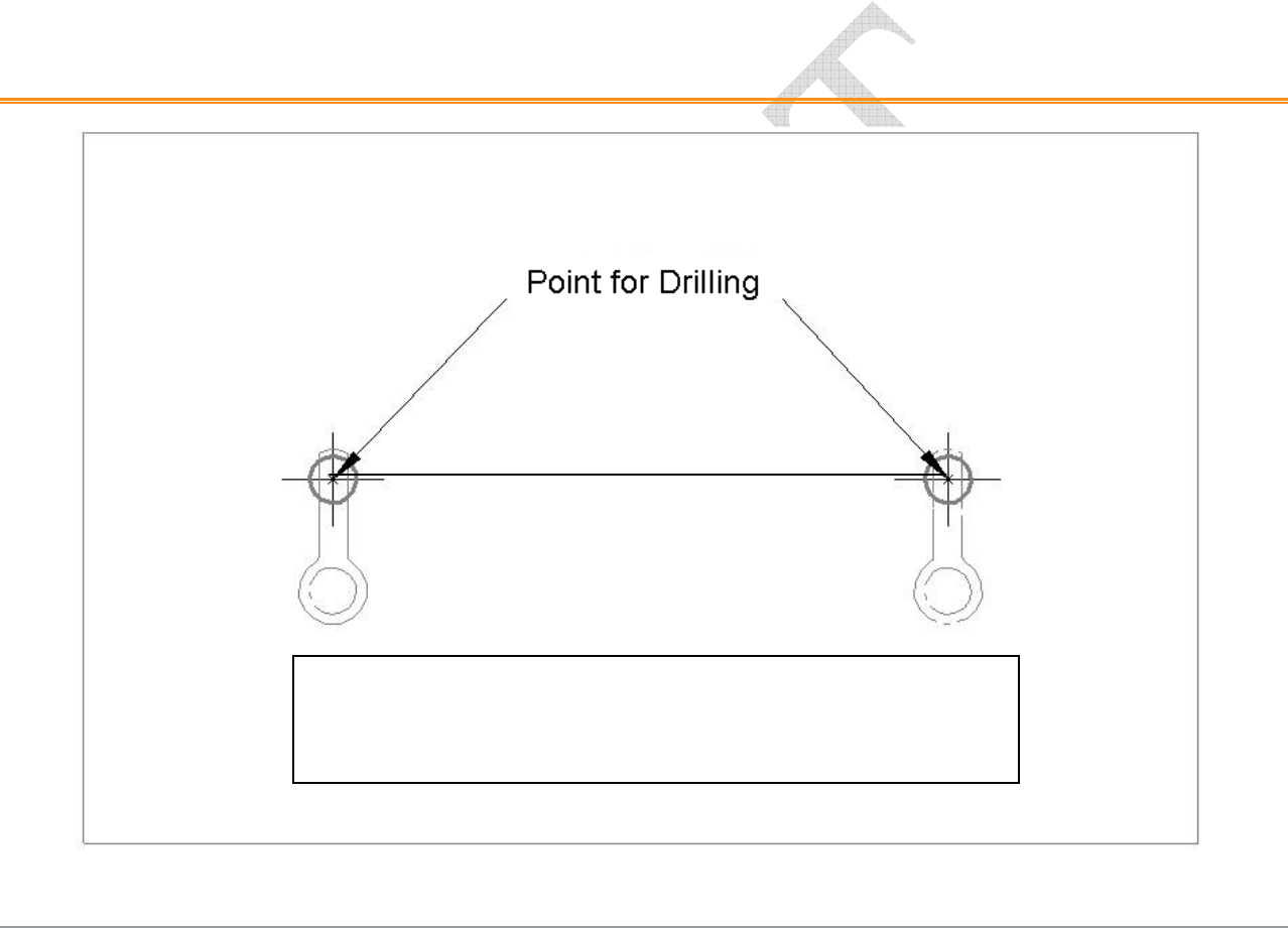
The Extricom WLAN System User Guide 65
Appendix B
Access Point Mounting Template
Figure 31. Access Point Mounting Template
4.25 inches
10.7
cm.
Important Note: Due to variations in printers, when printing this page,
printer Page Scaling should be set to “None” or diagram may be
automatically reduced in size. As a double-check, make sure distance
between drill points is as indicated above.

66 About This Guide