Extricom EXRP20E 802.11a/b/g Access Point User Manual Part 2 Revised
Extricom Ltd 802.11a/b/g Access Point Users Manual Part 2 Revised
Extricom >
Contents
- 1. Users Manual Part 1 Revised
- 2. Users Manual Part 2 Revised
Users Manual Part 2 Revised

The Extricom WLAN System User Guide 15
Chapter 2
Installing the Extricom WLAN System
This chapter provides instructions for unpacking and installing the Extricom WLAN system.
Unpacking the Extricom WLAN System
The Extricom WLAN system is shipped with the following:
One Extricom switch.
CD which contains The Extricom WLAN System User Guide and Release Notes.
APs (the number of APs is based on customer order and provided in separate boxes) are
shipped as part of the overall order.
One power cable.
Additional Equipment Needed
The following additional equipment is required for installing the Extricom WLAN system:
One CAT-5e/6 cable for each AP.
One CAT-5e/6 cable for connecting the WLAN switch uplink to the LAN switch.
One EXRE-10 Range Extender for any AP that will be located over 100 meters from the
WLAN switch.
Two stainless steel pan head 8x1-1/4" self-tapping Phillips screws for mounting each AP
(optional).
16 Installing the Extricom WLAN System
Determining the Location of the Extricom Access
Points
Before installing the switch and access points, plan the placement of the APs. Before permanently
mounting the APs, it is recommended to test the network (using a laptop client) to identify potential
coverage holes. If such a problem exists, relocate an AP or add additional APs to resolve the
coverage hole.
The APs should be placed in a stable, secure location, such as on top of a closet or bookshelf, or
mounted on a wall.
The switch should be placed near the distribution point of the LAN line. This is usually in the
communications closet of your enterprise.
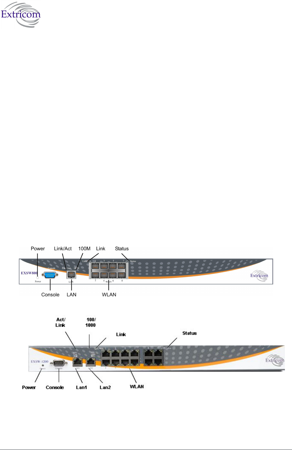
The Extricom EXSW800/1200/2400/8000 Switch
The Extricom EXSW800 switch has 10 connectors and 4 LED types on the front panel (refer to
Figure 10).
The Extricom EXSW-1200 switch has 15 connectors and 4 LED types on the front panel (refer to
Figure 11).
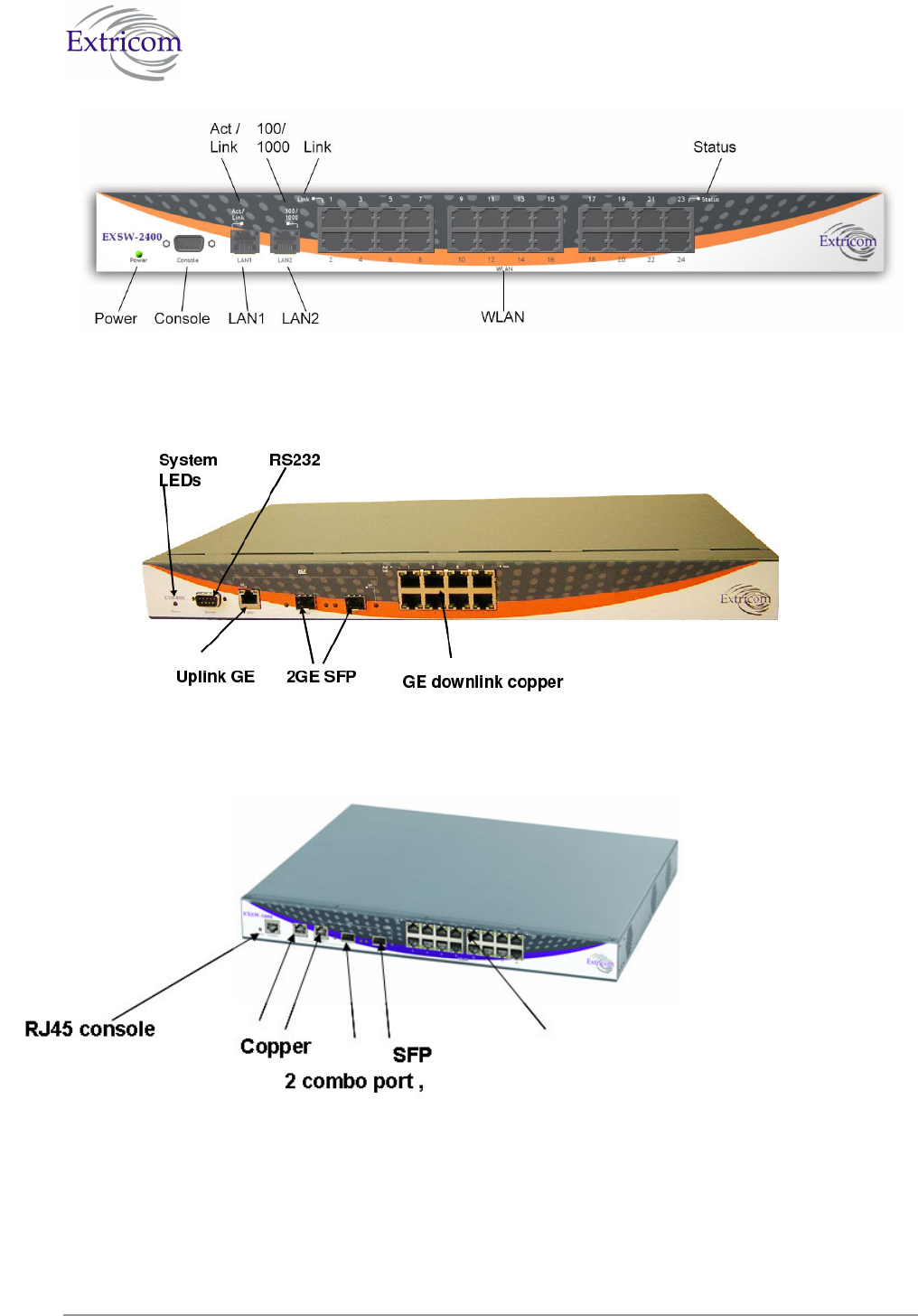
The Extricom EXSW-2400 switch has 27 connectors and 4 LED types on the front panel (refer to
Figure 12).
Figure 10. Extricom EXSW800 Switch
Figure 11 Extricom EXSW 1200 Switch
The Extricom WLAN System User Guide 17
Figure 12. Extricom EXSW-2400 Switch
Table 1 describes the front panel and connectors of Extricom EXSW800/1200/2400 switches.
Figure 13 Extriocm EXSW-8000 switch
Figure 14 Extriocm EXSW-1600 switch
16 WLAN copper ports16 WLAN copper ports

18 Installing the Extricom WLAN System
Table 1. Extricom EXSW800/1200/2400/8000/1600 Switch Connectors
Connectors Description
Console Serial connector – only to be used by, or as instructed by, Extricom
personnel for troubleshooting, support, or maintenance. Can be
accessed using a Null modem cable. (RJ45 in case EXSW-1600)
EXSW800
LAN
EXSW-
1200/2400
LAN1, LAN2
RJ-45 connectors – used to connect the switch to the wired LANs. On
EXSW-1200/2400 these connectors provide redundancy and load
sharing between them.
LAN2 is not currently active pending future development.
EXSW-1600
LAN1,LAN2
2 copper or SFP GBE combo ports , no mix copper/fiber is allowed
WLAN RJ-45 connectors – used to connect Extricom APs to the switch.
-
Do not connect any device other than Extricom APs to
the WLAN ports.
These ports provide 802.3AF PoE compatible power.
Maximum current: 270 mA, 48 volts.
Table 2 describes the front panel LEDs of Extricom EXSW800/1200/2400 switches.
Table 2. Extricom EXSW800/1200/2400 Switch LEDs
LEDs Color Description
Power Green On/off (blinking system not ready in EXSW-1600)
LAN, LAN1, LAN2
Link/Act Green
On indicates connection to the LAN network
Blinking indicates activity in the LAN network connection
Off indicates no connection to the LAN network
EXSW800
100M
Orange
On – 100Mbps full duplex
Off – 10Mbps
EXSW-
1200/2400
100/1000M
Orange
On – 100Mbps full duplex
Blinking – 1000Mbps full duplex
1000Mbps is not currently active pending future
development.
EXSW-1600 Orange Link status
WLAN
Link Green
On indicates connection to the WLAN AP
Blinking indicates activity over the connection to the WLAN
AP
Off indicates no connection to the WLAN AP
The Extricom WLAN System User Guide 19
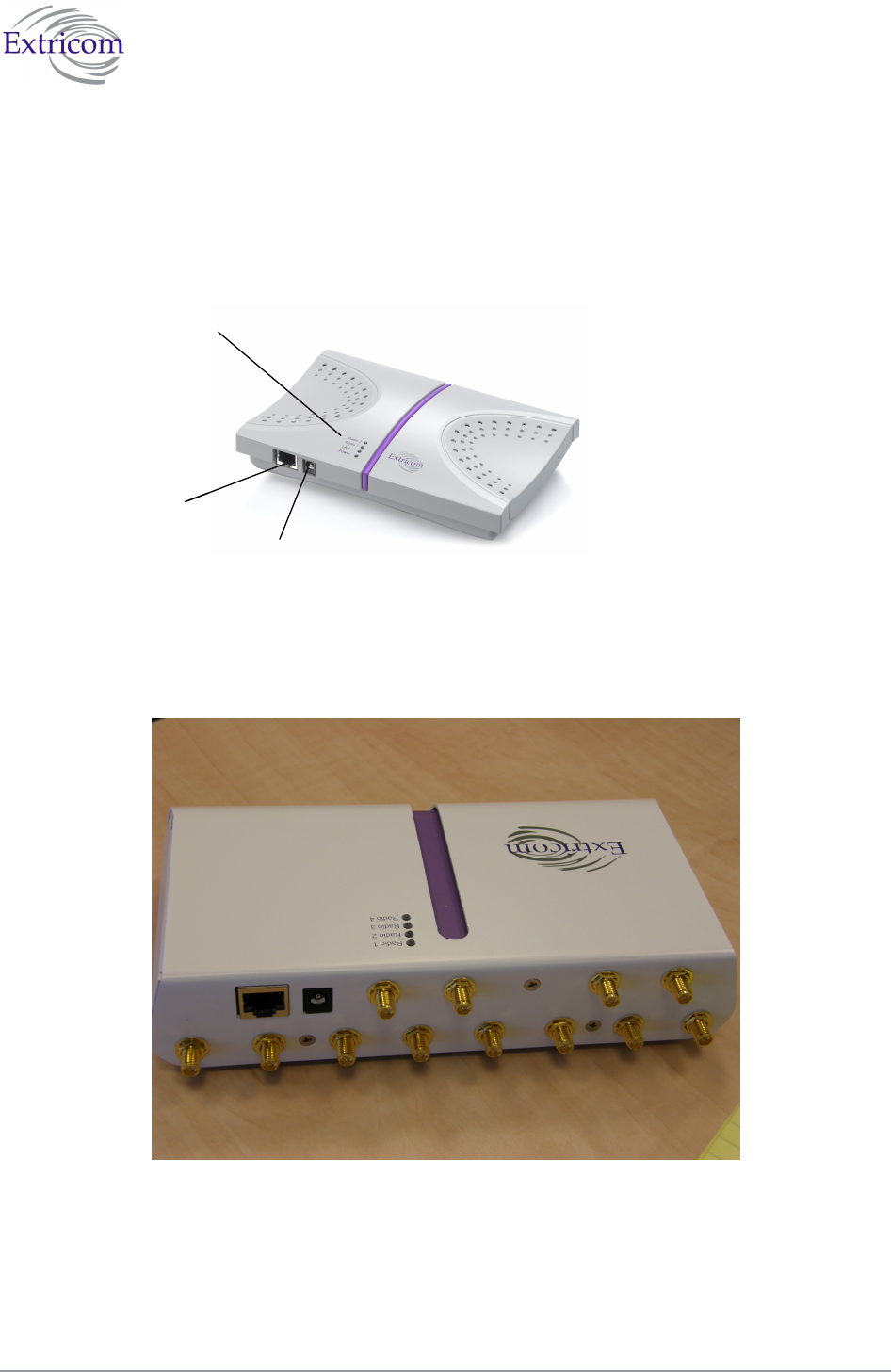
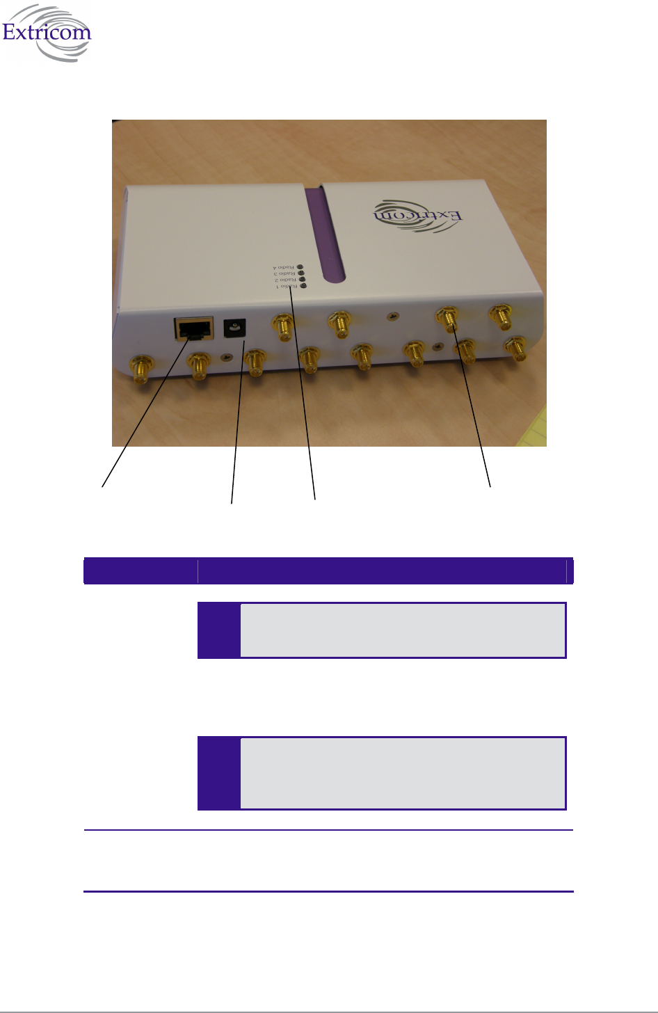
Extricom EXRP-20/40 EXRP-20/40 Access Points
Extricom APs have two connectors located on the side of the device and four LEDs located on the
top of the device.
LEDs
WLAN Connector
Power Connection
LEDs
WLAN Connector
Power Connection
Figure 15. Extricom EXRP-20/40 AP
Table 3 describes the Extricom Access Point connectors.
20 Installing the Extricom WLAN System
Table 3. Extricom AP Connectors
Connectors Description
Power
External power is not required for most
applications. Power is supplied through the
Ethernet (PoE).
In case of an external power requirement by the application,
use a UL Listed LPS (Limited Power Source) or NEC Class
II adapter. Rating – Input: 90-240VAC 0.8A max. Output:
48VDC 0.56A max.
-
Due to regulatory requirements and pending
certification process for the power supply
connector - external power supply should not be
used.
WLAN RJ-45 connector – used to connect the Extricom AP to the
Extricom switch. Power is provided by the Extricom switch
to the AP when directly connected to it.
Power connector Leds WLAN External
Antenna
Connector

The Extricom WLAN System User Guide 21
Table 4. Extricom EXRP-20 AP LEDs
LEDs Color Description
Radio 1 Green 1st Radio is active
Red 1st Radio is malfunctioning
Off 1st Radio is off
Radio 2 Green 2nd Radio is active
Red 2nd Radio is malfunctioning
Off 2nd Radio is off
LAN Green (flashing) Connection to Extricom switch is active
Off Not active
Power Green On/Off
Table 5 Extricom EXRP-40 AP LEDs
LEDs Color Description
Radio 1 Green 1st Radio is active
Red 1st Radio is malfunctioning
Off 1st Radio is off
Radio 2 Green 2nd Radio is active
Red 2nd Radio is malfunctioning
Off 3rd Radio is off
Radio 3 Green 3rd Radio is active
Red 3rd Radio is malfunctioning
Off 3rd Radio is off
Radio 4 Green 4th Radio is active
Red 4th Radio is malfunctioning
Off 4th Radio is off
The EXRP-20/EXRP-20 and EXRP-40/EXRP-40 are virtually identical in
appearance. Please double-check the label on the underside of the unit to make sure
you have the right type of AP for your deployment.

22 Installing the Extricom WLAN System
Connecting the Switch and Access Points
Extricom’s switch is connected to the wired LAN and the APs that are located throughout the
enterprise.
To connect the switch and access points:
1. Using a CAT-5e/6 100/1000Mbps cable, connect the switch RJ-45 LAN connector (located on
the front panel of the switch, (refer to Figure 12) to the LAN switch.
2. Using a CAT-5e/6 cable, connect each AP (refer to Figure 12) to one of the switch’s RJ-45
WLAN connectors. For those APs located over 100 meters from the switch, an Extricom
EXRE-10 Range Extender should be used.
3. Connect the power cable to the power connector located on the rear panel of the switch, and
plug the other end of the power cable into a power source.
4. Verify that the Power LEDs on both the switch and connected APs are green.
Additional APs can be connected/disconnected while the switch is active.
Mounting the Access Points (Optional)
Extricom APs can be mounted on the wall. To mount the APs, you will need two stainless steel pan
head 8x1-1/4" self-tapping Phillips screws.
To mount the Access Points:
1. Place the installation template (refer to Access Point Mounting Template on page 70) on the
wall where you want to mount the AP.
2. Mark the "Point for Drilling" locations on the wall.
3. Screw the two stainless steel pan head 8x1-1/4" self-tapping Phillips screws into the wall
leaving enough of the screws protruding to enable you to hook the AP over the screw.
4. Align the holes on the back of the AP with the screws and slip the AP into place.
Position the AP so that the connectors are on the bottom left corner of the AP.
The Extricom WLAN System User Guide 23
Chapter 3
Configuring the Extricom WLAN
System
After connecting the switch and AP, configure the Extricom WLAN system through Extricom’s
web configuration GUI using a terminal or PC connected to the same LAN as the switch.
To access the Extricom web configuration pages:
1. In your Web browser, enter the following: https://<IP address of the switch>
where <IP address of the switch> is the IP address of the switch provided with your
purchase (for example, the URL should be https://1.2.3.4 if the IP address of the switch is
1.2.3.4).
If you did not receive a switch IP address with the switch, the factory default value
for the switch IP address is 192.168.1.254.
If you are using the default IP settings, do not place a router between the user PC and
the switch.
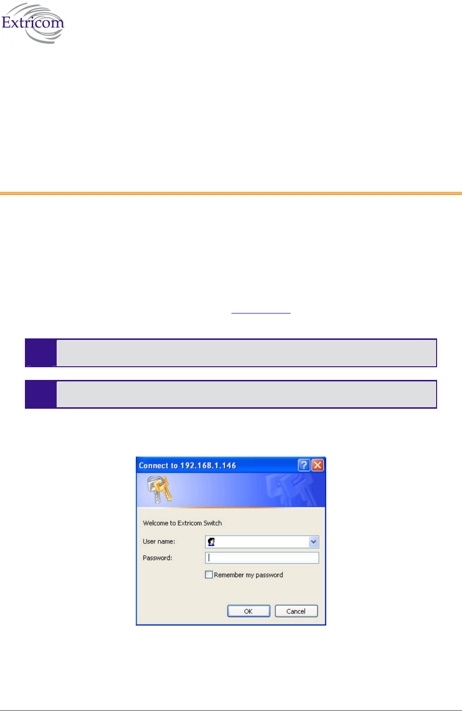
The Login page appears.
Figure 16. Login Page
2. Enter your user name and password (as provided by your system installer) and click OK. The
Summary page appears.
24 Configuring the Extricom WLAN System
If you did not receive a user name and password with your switch, use the following
factory default user name and password:
user name: admin
password: Switch1
The user name and password are case-sensitive.
Using the Extricom Web Configuration Pages
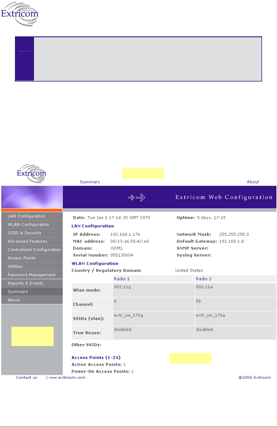
The Extricom Web configuration pages have three main areas:
The navigation tree
The menu bar
The work area
Figure 17. Typical Web Configuration Page
Navigation
Tree
Menu Bar
Work area
The Extricom WLAN System User Guide 25
The navigation tree provides access to the following Extricom Web configuration pages:
LAN Configuration – used for configuring LAN parameters as well as Events and Statistics.
WLAN Configuration – used for configuring WLAN parameters .
SSID & Security – used for configuring SSID and security parameters and/or passwords and
external RADIUS servers and their timeouts for redundancy.
Advanced Features– used for configuring redundancy, TrueReuse, 802.11d, IDS, SNMP
and Rogue AP detection parameters.
Centralized Configuration – used for configuration and control of remote switches from a
Master switch
Access Points – used for powering and activating/deactivating connected APs.
Utilities – used for viewing the system configuration file, or to restore system default
settings, upgrade the switch firmware, set the time and date manually or automatically, and
reboot the switch.
Password Management – used for changing system passwords.
Reports & Events – used for viewing system events and performance reports.
Summary – provides a comprehensive summary of the system configuration.
About – provides basic information about the Extricom WLAN system firmware versions.
Alternatively, you can access the:
Summary page by clicking Summary in the menu bar.
About page by clicking About in the menu bar.
The work area displays the configuration pages selected in the navigation tree. Use this area to
configure the Extricom parameters.
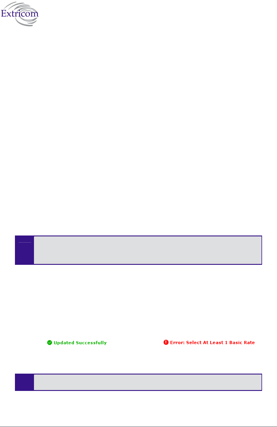
After changing the values of the configuration parameters on a web configuration page, you must
click Update to save the new configuration. An update status message appears at the top and
bottom of the page informing you if the update was successful (refer to Figure 18). If the update
was not successful, a description of the problem is displayed (refer to Figure 19).
Figure 18. Successful Update Message Figure 19. Unsuccessful Update Message
The new configuration only takes effect after rebooting the switch (refer to
Rebooting the Extricom Switch on page 56).
26 Configuring the Extricom WLAN System
Configuring the LAN Parameters
In the LAN Configuration page, you can configure the following:
The LAN IP address and network mask, as well as a backup address and mask.
The LAN interface and management VLAN tag IDs.
The default gateway.
The address of the System Log and how often (if at all) the log is written to.
The address of the Monitor Log and how often (if at all) the log is written to.
.
To configure LAN parameters:
1. Click LAN Configuration in the navigation tree. The LAN Configuration page appears (refer to
Figure 20).
Figure 20. LAN Configuration Page

The Extricom WLAN System User Guide 27
2. Configure the LAN parameters. Refer to Table 6 for a description of the LAN parameters.
Table 6. LAN Configuration Parameters
Field Description
IP Address Enter the main IP address of the Extricom Switch.
Network Mask Enter the network mask address.
VLAN Management VLAN tag ID for VLAN access to manage
the switch.
2nd IP Address Enter the backup IP address of the Extricom Switch.
2nd Network Mask Enter the backup network mask address.
2nd VLAN 2nd Management VLAN tag ID.
Default Gateway Enter the default gateway address.
The default gateway must be on the same
subnet as 1st or 2nd IP address.
Switch name A textual descriptor of the switch. Up to 32 characters.
Monitor On The Monitor Log is only relevant for a dedicated network
status monitoring tool that is not provided with the
switch. By default, this option should not be checked.
Check this option only if you are using the
Extricom dedicated network monitoring tool,
otherwise unnecessary data packets are sent
through the Ethernet.
Monitor Address Enter the address of the Monitor Log if using the
Extricom dedicated network monitoring tool.
Monitor Interval
(sec)
Specify how often information is sent to the Monitor
Log. If using the dedicated network status monitoring
tool, 1 second is the recommended interval.
Configure this parameter only if using the
dedicated network monitoring tool.
Syslog On Check the Syslog On option to record system information
in the System Log.
In most common operational scenarios, this
option should be unchecked (unless used for
troubleshooting).
Syslog Address Enter the IP address of the computer to which to send the
System Log.

28 Configuring the Extricom WLAN System
Field Description
Syslog Interval (sec) Specify how often information is sent to the System Log.
3600 seconds is the recommend default interval.
If you detect a problem, you can decrease
the Syslog Interval to receive updates more
frequently.
3. Click Update to save the configuration.
The new configuration only takes effect after rebooting or reconfiguring the switch
(refer to Rebooting the Extricom Switch on page 56).
Configuring WLAN Parameters
In the WLAN Configuration page, one can configure the following WLAN parameters for each
Radio (Radio 1 or Radio 2):
Channel options.
Data rates.
SSIDs.
There are up to 16 different SSIDs per channel, 32 SSIDs per system.
Refer to Configuring SSIDs on page 32 for an explanation of the relationships
between radios, channels, SSIDs, and VLANs.
To configure WLAN parameters:
1. Click WLAN Configuration in the navigation tree. The WLAN Configuration page appears
(refer to Figure 21).
2. Select the “Country / Regulatory Domain” which meets your locale from the list.
3. Click the Radio tab for which you want to configure the WLAN parameters.
4. Configure the WLAN parameters. Refer to Table 7 for a description of the WLAN parameters.
The Extricom WLAN System User Guide 29
Figure 21. WLAN Configuration Page
-
EXRP-40 - Radio 3 and 4 currently are not supported and do not appear in the Web
Configuration GUI.

30 Configuring the Extricom WLAN System
Table 7. WLAN Configuration Parameters
Field Description
Channel Options
Enable Check this box if you want to enable the radio.
WLAN Mode Select the WLAN mode. Possible options are:
802.11a
802.11b
802.11g for pure mode
802.11b/g for mixed mode
Since the Extricom solution can support
two simultaneous channels in the same
frequency band, selecting the WLAN
mode enables the Extricom solution to
offer same band capability. This means
that both radios can be set to:
1. 802.11a & 802.11a
2. 802.11b & 802.11b
3. 802.11b & 802.11g
4. 802.11g & 802.11g
5. 802.11b/g & 802.11b/g
And any other combination.
Channel Select the channel. The options available are based
on the country and WLAN mode.
Maximum Retries Select the number of times to try to resend a packet
if the transmission of the packet fails.
Allow Rate
Adaptation
Check this box if you want to enable rate adaptation.
All enabled rates participate in the rate
adaptation..

The Extricom WLAN System User Guide 31
Field Description
Rate Configuration For each of the data rates listed, select whether the
rate is Basic, Optional, or Disabled.
When configuring the data rates, you should
consider the data rate capabilities of the wireless
devices in your enterprise.
Basic – The Basic data rates are usually the data
rates that the vast majority of your wireless
devices can support. Only wireless devices that
support all the Basic data rates will be connected
to the WLAN system. Therefore, it is
recommended that you configure a minimal
number of Basic data rates that the vast majority
or all your wireless devices can support. When
working in Mixed Mode, there should be at least
one Basic data rate from the 802.11b rates.
Optional – If you configure a data rate as
Optional, the network will provide that data rate
to wireless devices that can support it.
Disabled – Disabled data rates are not available
to wireless devices.
Since the Extricom WLAN system allows
for dense deployment of APs, it is
recommended, where applicable, to
disable low data rates. Not doing so could
possibly lead to an “edge user” effect, in
which a client reduces aggregate network
throughput by moving to the edge of the
coverage area.
Short Preamble: This option becomes available only when selecting
802.11b as the WLAN mode. In this case, mark the
checkbox to allow a short preamble.
Setup SSIDs
Assigned SSIDs Displays the list of SSIDs assigned to the channel.
Remove from
Channel
To remove an SSID from the channel, select an
SSID and check the Remove from Channel option.
The SSID is removed from the Assigned SSIDs list,
and appears on the Unassigned SSIDs list after
clicking Update.
In the Extricom WLAN system, a single
channel can support up to 16 different
SSIDs (system limit of 32).

32 Configuring the Extricom WLAN System
Field Description
Other SSIDs Displays the list of SSIDs configured but not
assigned to the channel.
Add to Channel To add an unassigned SSID to the channel, select an
SSID from the Other SSIDs list and check the Add
to Channel option. The selected SSID is removed
from the Other SSIDs list and added to the Assigned
SSIDs list after clicking Update.
New SSID To create a new SSID and assign it to the selected
channel, enter a unique SSID name and check the
Create and Assign option. The new SSID is added to
the Assigned SSIDs list after clicking Update.
The character Space may be used in SSID
name.
Create and Assign Check to assign the new SSID. The new SSID is
added to the Assigned SSIDs list after clicking
Update.
All SSIDs Displays a list of all SSIDs configured for the
switch. (assigned/unassigned)
Delete Permanently To delete an SSID from the switch, select an SSID
from the All SSIDs list and check the Delete
Permanently option. The SSID is removed from any
list on which it appears after clicking Update.
5. Click Update to save the configuration.
The new configuration only takes affect after rebooting or reconfiguring the
Extricom Switch (refer to Rebooting the Extricom Switch on page 56).
6. To configure WLAN parameters for another radio, click the tab for that radio, configure the
WLAN parameters, and click Update to save the configuration.
7. To configure SSID and security settings, click Edit SSID & Security Setting. Refer to
Configuring SSIDs on page 32, and Configuring Security Definitions on page 37.
To configure SSID and security settings, you can also click SSID & Security in the
navigation tree.
Configuring SSIDs
An SSID (Service Set Identifier) is the name of the network. Wireless devices must connect to a
specific SSID which determines the pre-defined set of privileges, settings, and limitations (such as
security definitions, access privileges, VLAN assignments, etc.) of the network. Each channel can
support multiple SSIDs, thus creating “virtual” networks on the same channel.

The Extricom WLAN System User Guide 33
The following is the data structure used by the Extricom system:
Each radio is assigned one channel.
Each channel can support up to 16 different SSIDs.
Each SSID can be associated with a VLAN tag.
The same SSID name cannot be repeated for different channels.
Table 8 shows this data structure with an example of possible channel, SSID and VLAN tag
assignments.
Table 8. Data Structure Example
Access Point Channel SSID VLAN tag
Network1 1
Network2 2
… …
… …
Network15 15
First Radio 1
Network16 16
Network17 17
Network18 18
… …
… …
Network31 31
Second Radio 6
Network32 32
In the SSID & Security page, SSID Options section, the following SSID parameters can be
configured to:
Allow Default SSID.
Display SSID in Beacon.
Allow Store & Forward.
Allow Inter-Ess Store & Forward
Enable Multicast
ARP Caching
Assign a VLAN to the SSID.
Set a disassociation timeout.
Set DTIM period.
34 Configuring the Extricom WLAN System
To configure SSID parameters:
1. Click SSID & Security in the navigation tree. The SSID & Security page appears (refer to
Figure 22).
Figure 22. SSID & Security Page
2. Configure the SSID parameters. Refer to Table 9 for a description of the SSID parameters.

The Extricom WLAN System User Guide 35
Table 9. SSID Parameters
Field Description
SSID
Choose SSID Select an SSID from the Choose SSID dropdown
list.
To add/remove SSIDs from this list, click WLAN
Configuration (refer to Table 7).
SSID Options
Allow Default SSID If this option is enabled, a wireless device will be
allowed to connect even without requesting a
specific SSID (i.e., “default” or “any” SSID) to the
Extricom WLAN. If this option is disabled, then a
wireless device needs to connect to a specific SSID
in the Extricom WLAN.
Display SSID in
Beacon
This option provides an additional (though limited)
level of security. The AP sends out a beacon with
information about the network. If this option is
enabled, the SSID appears in the beacon. If disabled,
the SSID does not appear in the beacon.
Allow Store &
Forward
If this option is enabled, two wireless devices
connected to the Extricom WLAN with the same
SSID can communicate and transfer data to each
other. Traffic between wireless devices will not be
forwarded to the LAN switch.
If this option is disabled, all traffic goes through the
LAN switch. . This could be used by IT managers to
apply security settings or various policies in the
LAN network.
Disabling Allow Store & Forward disables
the Allow Inter-Ess Forward option.

36 Configuring the Extricom WLAN System
Field Description
Allow Inter-Ess
Forward
If this option is enabled, two wireless devices
connected to the Extricom WLAN with different
SSIDs will be able to communicate with each other
without going through a router. Traffic between
wireless devices will not be forwarded to the LAN
switch.
This option must be enabled on both SSIDs.
In order for wireless devices, associated to
different SSIDs, to be able to communicate
with each other, the SSIDs must be defined
on the same VLAN (or no VLAN at all).
If this option is disabled, all traffic goes through the
LAN switch. This could be used by IT managers to
apply security settings or various policies in the
LAN network.
Enable Multicast This option, when enabled, provides support of
multicast and broadcast packets for the selected
SSID. Multicast and/or broadcast packets shall be
transmitted from all APs.
ARP Caching This option, when enabled, provides an immediate
response to ARP requests directed towards WLAN
stations associated with the selected SSID. The
Switch answers on behalf of the WLAN stations.
MAC ACL This option, when enabled, allows a user to add a
MAC access list to the specific SSID. Only clients
with MAC address included in this list are allowed
to access the network.
802.1d Support Enables support of the 802.11d standard .The
purpose of this standard is to provide regulation
domains for each country in a predefined list. The
regulation domains and Country information are
provided as part of Beacons & Probe response.
VLAN Enter a VLAN tag to assign to the SSID. Assigning
a VLAN to an SSID enables you to control a
wireless devices’ privileges through the existing
wired network definitions.
Disassociation
Timeout
Enter the amount of time (in seconds) a wireless
device can remain inactive (no data sent to or from
the wireless device) before automatically
disconnecting from the network.

The Extricom WLAN System User Guide 37
Field Description
DTIM Period The period of time after which broadcast and
multicast packets are transmitted to mobile clients in
the Active Power Management mode.
Select the DTIM period for the selected SSID. This
is relevant for clients that want to utilize the power
management capability. The possible values are 1-5.
The default is 3.
A high DTIM value may cause these
clients to lose connection with the
network.
The remaining parameters in the SSID & Security page are described in Configuring
Security Definitions on page 37).
3. Click Update to save the configuration.
The new configuration only takes affect after rebooting the switch (refer to
Rebooting the Extricom Switch on page 56).
Configuring Security Definitions
In the SSID & Security page Encryption & Authentication section (refer to Figure 22), the following
security definitions can be configured:
Type of encryption.
Type of authentication.
With some configurations, you can use encryption without authentication. However,
for a higher level of security, it is recommended to use both encryption and
authentication.
Extricom system eases the configuration of the SSID security parameters by
providing a list of available combinations of Encryption and Authentication protocols
Security definitions are configured for each SSID individually.
To configure the security definitions:
1. Click SSID & Security in the navigation tree. The SSID & Security page appears (refer to
Figure 22).
2. Select the SSID from the Choose SSID dropdown list for which you want to configure the
security definitions.

38 Configuring the Extricom WLAN System
3. Configure the security definitions for the selected SSID. Refer to Table 10 for a description of
the Security parameters.
Table 10. Security Definition Parameters
Field Description
Encryption & Authentication
Choose method Define the method of encryption and authentication.
A combination of encryption and authentication methods may be
selected from the options detailed in the drop-down list.
Encryption cipher
There are three types of encryption ciphers available:
WEP64 – Wired Equivalent Privacy (802.11 encryption
protocol). This is a very basic encryption level. (AKA WEP40)
WEP128 – This encryption is similar to WEP64, but the WEP
keys are longer. (AKA WEP104)
TKIP – Temporal Key Integrity Protocol. This is a more secure
and more advanced method of encryption as a part of the WPA
standard.
AES (CCMP) – Advanced Encryption Standard.(Cipher Block
Chaining Message Authentication Code Protocol) is currently
the most advanced and secured method of WiFi encryption and
is part of 802.11i (WPA2) standard.
Authentication method
Authentication is used to identify if a wireless device is authorized
to connect to the WLAN, and verifies the wireless device’s
identity. Authentication methods (such as specific EAP methods
available in the WPA/WPA2 (RADIUS) option) also verify that the
association process is secured. Authentication utilizing
WPA/WPA2 (RADIUS) can also support encryption key changes.
The following methods are available:
802.1x – if the cipher is WEP or WEP104
WPA/WPA2-PSK or WPA/WPA2 (RADIUS) – if the cipher is
TKIP or AES
Supported protocols: EAP, TLS, TTLS, PEAP, LEAP and MD5
When choosing the encryption cipher and authentication
methods, one should take into account wireless devices’
capabilities.
The Extricom system supports “WPA2 Mixed Mode”.
This mode permits the coexistence of WPA and WPA2
clients on the same SSID. WPA2 mixed mode allows
“Old” WLAN clients with “New” WLAN clients on
the same SSID during transition period.

The Extricom WLAN System User Guide 39
Field Description
Any security combination (Encryption and Authentication) can be
selected by the user as a combination of the list and the check
boxes.
WEP Keys The WEP Keys area is only enabled if the cipher selected in the
Choose Method field is WEP or WEP104. In the WEP Keys area,
you define the WEP Key that is used for encrypting or decrypting.
You can define all four WEP keys. For each key you define, select
the input format (ASCII or HEX) and enter the key according to
the following table:
Cipher ASCII HEX
WEP64
(or WEP64+802.1x)
5 characters 10 digits
WEP128
(or WEP128+802.1x)
13
characters
26 digits
Transmission Key Select the WEP64/WEP128 key to be used for transmitting the
data from the AP.
WPA The WPA area is only enabled if the cipher selected in the Choose
Method field is WPA/WPA2 TKIP/AES.
WPA-PSK If WPA/WPA2 with Pre-Shared key authentication is used, the
WPA-PSK field is enabled. In this case, select one of the
following input formats, and enter the corresponding key listed:
For ASCII, enter 8-63 characters.
For HEX, enter 64 digits.
WPA/RADIUS
Re-key Interval Enter the amount of time (in seconds) that elapses before the
Group Key is changed.
RADIUS Define the RADIUS servers parameters if:
The cipher is WEP64/WEP128, and the 802.1x authentication
method is selected.
The cipher is TKIP/AES, and the WPA/WPA2 (RADIUS)
authentication method is selected.
Server Address Enter the address of the RADIUS server.
Use Server # 1 if only one server is used. Use
consecutive servers if several servers are used.
Server Port Enter the RADIUS server port.
Server Password Enter the RADIUS server password.
Server Timeout Enter the time which the Extricom switch waits for the RADIUS
server response.

40 Configuring the Extricom WLAN System
Encryption and Authentication methods.
The “Choose Method” drop down list in “Encryption & Authentication” displays the following
items for user selection:
None
WEP64 (Open)
WEP128 (Open)
WEP64 & 802.1x Authentication
WEP128 & 802.1x Authentication
WPA/WPA2 TKIP/AES & Pre Shared Key Authentication
WPA/WPA2 TKIP/AES & 802.1x Authentication
When the “WPA2 Only” is checked, only Clients with WPA2 support are allowed access to the
WLAN.
When the “AES Only” is checked, only Clients with AES support are allowed access to the WLAN.
Cisco LEAP protocol (not CMIC & CKIP) is supported under “WEPxxx & 802.1x Authentication”.
Multiple RADIUS and RADIUS redundancy
RADIUS is a common authentication protocol utilized by the 802.1x security standard (often used
in wireless networks). Although RADIUS was not initially intended to be a wireless security
authentication method, it improves the WEP encryption key standard, in conjunction with other
security methods such as EAP-PEAP.
In an enterprise environment, several RADIUS servers may be used for backup and also for serving
different geographical locations. Up to four different RADIUS servers can be defined for each
SSID. RADIUS redundancy is based on the assumption that the user database is identical in all
RADIUS servers and that users are listed in all servers with the same credentials.
Switchover from one RADIUS server to another takes place after consecutive failures of the server.
The order of priorities is 1 to 4.
4. Click Update to save the configuration.
The new configuration only takes affect after rebooting or reconfiguring the
switch (refer to Rebooting the Extricom Switch on page 56).
The Extricom WLAN System User Guide 41
Advanced Configuration of the Extricom WLAN
Architecture
The advanced configuration page of Extricom WLAN includes the following tabs:
TrueReuse
Advanced
Rogue
IDS
Advanced Tab
The Advanced tab includes the capability to configure the following:
Redundancy parameters.
SNMP parameters.
802.1d parameters
In redundancy mode, two identical switches (H/W and configuration) are installed with the same
number of connected APs.
One of the switches is configured as the Main switch, while the second is in Stand-by mode, and
can switch over as soon as the switch-over conditions are met.
Figure 23. Redundancy deployment
Main
Stand
-
by

42 Configuring the Extricom WLAN System
To configure the Advanced Features parameters:
1. Click Advanced Features in the navigation tree. The Advanced configuration page appears
(refer to Figure 24 ).
2. Select Advanced tab for configuring redundancy, TrueReuse and/or SNMP and/or 802.11d
parameters
3. Configure the redundancy, and SNMP parameters. Refer to Table 11 for a description of the
Advanced Features configuration information.
4. Select Rogue tab for configuring Rogue AP detection and parameters (refer to Figure 25).
5. Configure Rogue AP parameters. Refer to Table 12 for a description of the Rogue AP
configuration information.
The Extricom WLAN System User Guide 43
Figure 26 Advanced Features

44 Configuring the Extricom WLAN System
Table 12. Advanced Configuration Tab
Field Description
True Reuse Select True Reuse in the appropriate Radio checkbox if you
wish to use this mechanism.
TrueReuse technology multiplies the bandwidth of a standard
802.11 channel by dynamically optimizing the reuse of each
frequency. Within a channel blanket, up to three APs are
permitted to simultaneously transmit on the same channel, when
the TrueReuse algorithm determines that they can do this
without causing each other co-channel interference
Redundancy Status Enables designating pairs of switches, one as active and one as
standby.
Monitored IP The IP address of the other switch.
Reference IP The IP address of a reference network element. This is used to
test connectivity to the LAN.
Keep Alive Interval The interval in mSec between the Keep Alive packets.
Keep Alive Check
Threshold
The number of lost keep-alive packets before switching to the
stand-by switch.
SNMP
Enable Traps Check this option to enable SNMP traps.
Community name Enter the community name.
Manager IP Enter the manager’s IP address.
802.1d
All ESSID Enabled for all SSIDs
Per SSID For a specific SSID , you need to enable this option then go to
SSID & Security to set the 802.1d option for that SSID.
At present, the following Traps are sent from the Extricom switch to the device on the LAN running
the SNMP manager.
1. Client <Client MAC> has associated to <SSID> - This trap is sent after successful association
with the client MAC address and the SSID the client associated to.
2. Client <Client MAC> has disassociated from <SSID>. Reason: <Reason> - This trap is sent
after client disassociation/disconnection from an SSID. The reason code is an 802.11 reason
code.
3. Key error! Client: <Client MAC> - SSID: <SSID> - Cipher suite: <Cipher> - This trap is sent
in case of any key error during four-way handshake (MIC error) or as a result of any key error
when receiving data from client..
4. New Rogue Detected <BSSID><Port><Radio><Channel><RSSI> - This trap is sent when a
new Rogue AP is detected. The trap includes the AP’s BSSID, the switch port which detected
the Rogue AP, the channel of the Rogue AP and the Rogue AP signal level (RSSI).
5. Rogue Updated <BSSID><Port><Radio><Channel><RSSI> - This trap is sent when an
existing previously detected Rogue AP is re-detected with change in one of its parameters. The

The Extricom WLAN System User Guide 45
trap includes the AP’s BSSID, the switch port which detected the Rogue AP, the channel of the
Rogue AP and the Rogue AP signal level (RSSI).
6. Rogue Removed <BSSID><Port><Radio><Channel><RSSI> - This trap is sent when a new
Rogue AP is detected. The trap includes the AP’s BSSID, the switch port which detected the
Rogue AP, the channel of the Rogue AP and the Rogue AP signal level (RSSI).
7. RADIUS Timeout <ESSID><# of timeouts> - This trap is sent when the RADIUS timeout had
elapsed and includes the ESSID and the number of timeouts that occurred.
8. RADIUS Redundancy Selection Changed <ESSID><#of RADIUS>to<# of RADIUS> - This
trap is sent when the RADIUS selection has been changed from one server to another, and
includes the ESSID, the number of the previous server and the number of the new server.
9. No RADIUS <ESSID> - This trap is sent when the last RADIUS server failed and includes the
ESSID.
10. Configured and connected APs of channel [<channel number>] - This trap provides a
summary of all APs and their status. This trap is typically sent after an event of AP removal or
connection from/to the switch.
11. AP <ap number in hex base> has been connected - This trap is typically sent after an event of
connecting an AP to the switch.
12. AP <ap number in hex base> has been disconnected - This trap is typically sent after an event
of disconnecting an AP from the switch.
13. Reference Host is up – This trap is sent when the Reference host is up and active. Sent by the
Main switch.
14. Reference Host is down - This trap is sent when the Reference host is down. Sent by the Main
Switch.
15. Standby Switch is up - This trap is sent when the Standby Switch is up & active.
16. Standby Switch is down - This trap is sent when the Standby Switch is down.
17. Inactive - Reference Host is down - This trap is sent when the Reference host is down, and
hence the Main switch becomes inactive.
18. Inactive Standby Switch - Main Switch is up - This trap is sent when the Main Switch becomes
active again and hence the Standby Switch becomes inactive (Switch over).
19. Main Switch is active again - This trap is sent when the Main Switch changes status from
inactive to active and regains the Main switch status.
20. Failure detected in Main Switch - Switching Over. - This trap is sent when the Main Switch is
about to go down and the Standby Switch is becoming Active.
Rogue Tab
A “Rogue” AP is an AP which is connected to an organization’s wired LAN without proper
authorization. Such an AP represents a security hazard since the organization cannot control that
AP’s over-the-air security measures.
Rogue APs pose threats to the enterprise. These threats vary and may include any of the following:
WEP key cracking.
Password hijacking.
IP and MAC spoofing.
Channel jamming.
To configure Rogue AP detection parameters refer to Table 13 and Figure 27
46 Configuring the Extricom WLAN System
Table 13: Rogue AP Tab
Field Description
Enable Enables Rogue AP detection function
When Rogue AP detection is enabled the 2nd
radio is not used for service.
Allowed BSSIDs
Displays a list of authorized APs (White List)
Remove Removes checked BSSIDs from the white list.
Edit Provides capability of editing the white list
Add BSSID
Add Adds the BSSID in the text box to the white list. BSSIDs may
be added from events log.
Figure 27: Rogue AP configuration.
The Extricom WLAN System User Guide 47
IDS Tab
Intrusion detection system (IDS): Malicious WLAN clients can cause a denial of service by
flooding the WLAN network. Denial of services is identified through attack signatures or other
factors, most of which are well-known. The IDS tab allows the user to enable this mechanism, set
thresholds for identifying an attack and choose type of attack to be detected. The IDS mechanism
detects 802.11 duration attack and 802.11 management messages flooding attacks. Upon attack
detection, the system sends a Trap message notifying the event and when applicable provides
attacker details (i.e. MAC address). Network administrator can use this information to take action
and block malicious users.
Figure 28: IDS Configuration

48 Configuring the Extricom WLAN System
Table 14: IDS Tab
Field Description
Enable Enables Intrusion detection
Duration Attack
Enable Enable - tick duration attack check box
Duration Attack WLAN devices reserve the channel for a particular period of
time and then start using the radio channel. This reservation of
channel is for a particular period of time. This time period is the
Network Allocation Vector (NAV) in the 802.11 .By using high
NAV values an attacker can prevent other WLAN devices to
utilize the wireless network.
Check box 11b/g , 11a The Max NAV period after which attack is discovered.
Flood attacks
Malicious users can flood the WLAN with 802.11 management messages
Events thresholds Number of events per second
Per station Number of time a specific event is allowed during the event
threshold. Each of the possible attack types listed below is
assigned a limit per station.
All station Number of times a specific event is allowed during the event
threshold. Each of the possible attack types listed below is
assigned with a limit to all stations
Authentication Flood Flooding the WLAN with authentication requests
De-Authentication
Flood
Flooding the WLAN with De-authentication requests
Association Flood Flooding the WLAN with association requests
Dis-Association Flood Flooding the WLAN with Dis-association - requests
Invalid Authentication
Request
Flooding the WLAN with Invalid authentication requests
EAPOL Start Flooding the WLAN with EAP authentication ”EAPOL Start”
EAPOL Logoff Flooding the WLAN with EAP authentication ”EAPOL Logoff”
The Extricom WLAN System User Guide 49
Centralized Configuration Settings
Centralized Configuration allows managing a group of identical Extricom switches (slaves) from
one single master switch. The user should decide which switch will act as master. Extricom
Switches have a built-in mechanism to discover the presence of other switches. In addition, the user
is given the ability to manually configure the entries in the table of switches.
Configuration changes on the master switch are propagated to the slave switches via a secured
mechanism. For this authentication scheme to work, the slave switches need to obtain a copy of the
master's public key prior to the centralized configuration. This is done in the initial phase of the
switch’s configuration by first retrieving the master's public key and then uploading it to the
designated slave switches.
Figure 29. Central Configuration Page
50 Configuring the Extricom WLAN System
To configure Centralized Configuration parameters:
Initial Setup
1. Configure the LAN settings on the Master switch
2. Generate an SSH key pair on the Master switch. This is done by clicking on the Update
button next to the generate New SSH Keys.
3. Retrieve the SSH public key from the Master switch and save it in a file on your PC.
4. Manually configure each of the Slave switches’ LAN settings, and continue by uploading
the previously saved master's public key on every Slave you wish to manage. This allows
the Slave switch to be configured only by the Master switch which generated the public
key.
Figure 30. Central Configuration Page
Slave Switch Configuration
1. On the Master switch, open the Centralized Configuration web page and click on the
Update button in the Switches Table section. This will retrieve and generate the Slave
switches’ information and all the relevant dialog boxes will be populated with data.
2. Slave switches can be added to the switches table by creating a new entry. Simply enter the
new switch name and its IP address, and continue by clicking on the Update button.
3. Configure a slave switch, i.e. Copy the configuration file of the master with appropriate
changes to the slave.
Figure 31. Action options
4. Reboot the Slave switches.
The Extricom WLAN System User Guide 51
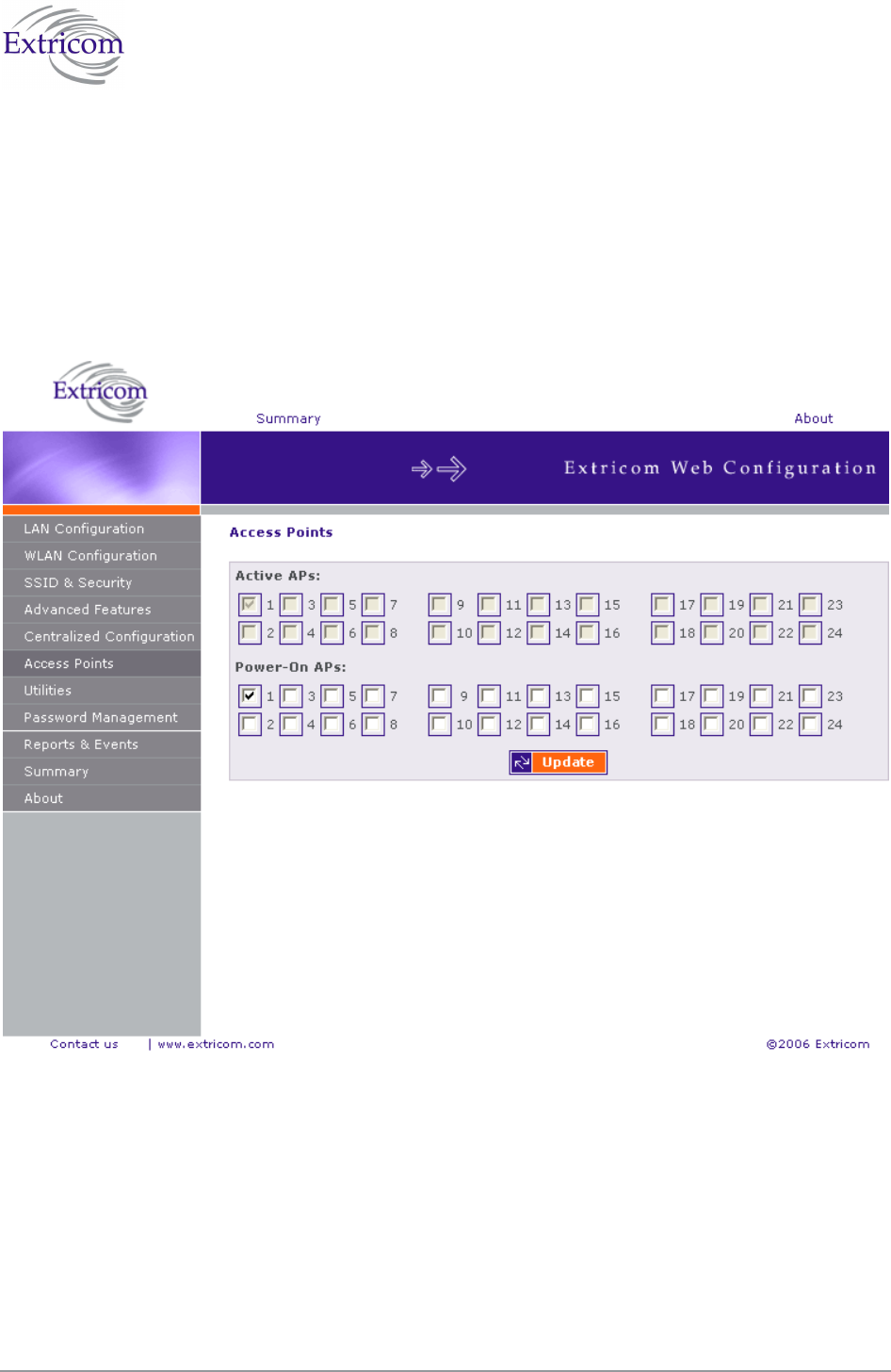
Access Point Powering
The only configuration required for APs in the Extricom WLAN architecture is activation or
deactivation of specified AP ports..
To access the Access Points page:
Click on the Access Points in the navigation tree. The APs configuration page appears
(refer to Figure 32).
Figure 32. APs Configuration Page
To configure APs:
Configure the APs and click Update. Refer to Table 15 for a description of the APs
configuration information.

52 Configuring the Extricom WLAN System
Table 15. AP Configuration Page
Field Description
Active APs Checked boxes indicate ports with attached and configured APs.
If a port is “powered” but not “active”, the AP is
malfunctioning. This field is read-only.
Powered APs Checked boxes indicate ports with attached and powered-on
APs. Un-checking a box will turn off the power on the AP. The
box must be re-checked to enable the port.
You do not need to reboot the switch for changes in AP configuration to take effect.
The Access Points page of the EXSW800 displays 8 check boxes. The Access Points
page of the EXSW-1200 displays 12 check boxes.

The Extricom WLAN System User Guide 53
Configuration of the Extricom WLAN Architecture
Utilities
The utilities page includes two tabs and serves the following function:
Viewing the System Configuration File.
Uploading a new Configuration File (replace existing).
Upgrading Extricom Firmware.
Reconfiguring the Extricom system
Rebooting the Extricom switch.
Setting the Time and Date (separate tab).
To access the Utilities configuration pages:
Click Utilities in the navigation tree. The Utilities configuration page appears (refer to
Figure 33).
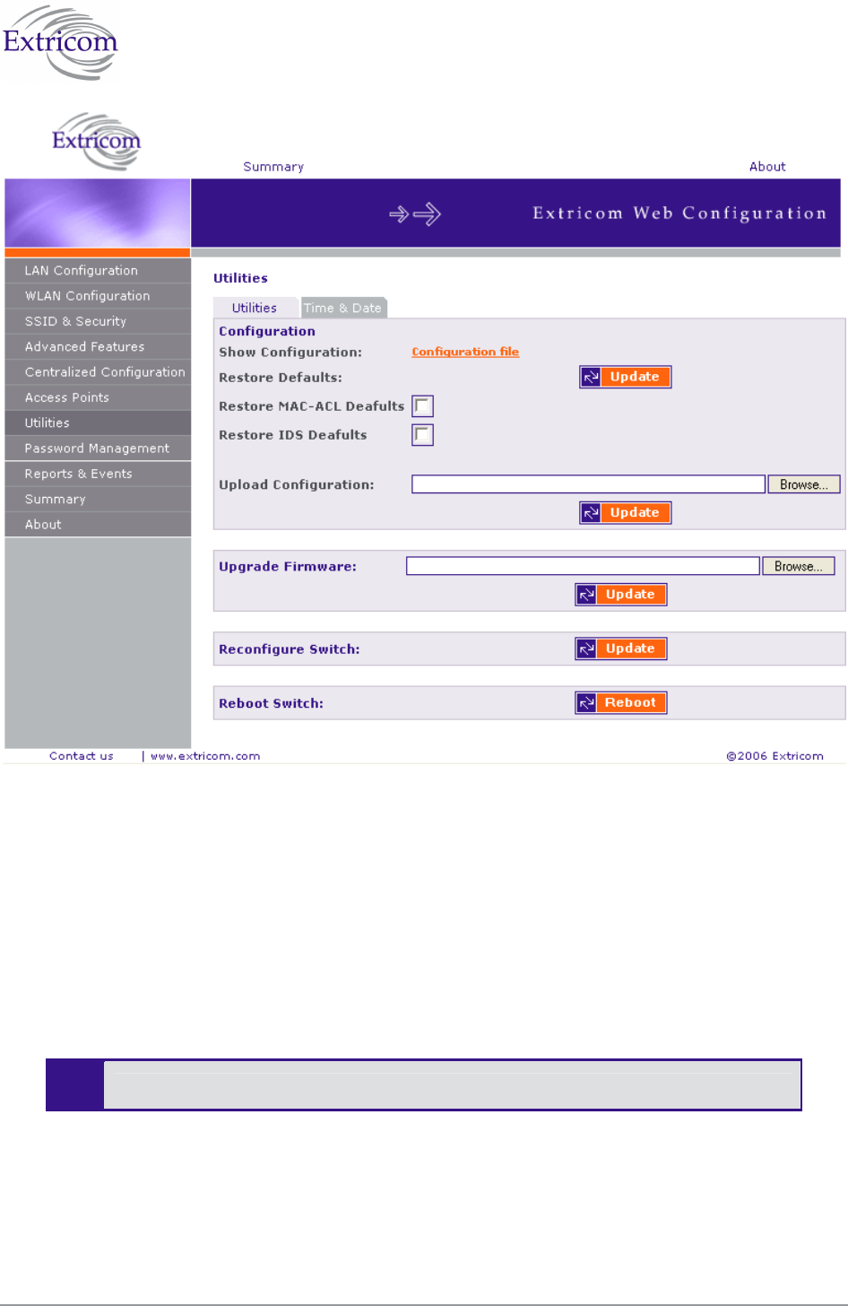
54 Configuring the Extricom WLAN System
Figure 33. Utilities Configuration Page
Viewing the System Configuration File
The system configuration file contains all of the parameters that are configurable through the
configuration utility.
To view the system configuration:
1. In the Configuration section of the Utilities configuration page, click Configuration file. The
system configuration file appears in your Web browser.
2. Review the configuration in the XML file.
To return to the Extricom web configuration pages, click Back in your Web browser.
Configuration File Backup
You can create a backup file of the current configuration to upload in the future. This is an optional
procedure.

The Extricom WLAN System User Guide 55
To back up a configuration file:
1. In the Show Configuration section of the Utilities page, right-click Configuration file and select
Save Target As. The File Download dialog box opens, and then the Save As dialog box opens.
2. Select the location in which to save the configuration file and click Save. The configuration file
will be saved to the selected location.
Uploading a New Configuration File
A previously saved configuration file can be uploaded (e.g., a file saved for backup purposes).
To upload a new configuration file:
1. Backup the current XML configuration.
2. In the Upload Configuration section of the Utilities configuration page, click Browse and
browse to the location of the configuration file that you want to upload. The file’s path appears
in the Upload Configuration field.
3. Click Update to update the configuration.
4. Click Reboot at the bottom of the page to reboot the switch.
Make sure that you are uploading a valid configuration file.
Restoring System Defaults
Restores the switch to its default configuration.
To restore system defaults:
In the Utilities page, Configuration section Restore Defaults, click Update. The switch’s
defaults are restored. You can also choose to restore MAC ACL and IDS Defaults by
choosing the appropriate box.
Upgrading the Extricom Firmware
Extricom firmware can be easily upgraded using Upgrade Firmware.
To upgrade the Extricom firmware:
1. Download the upgrade to your computer from the CD supplied with your purchase.
or
Obtain an upgrade file from your authorized Extricom reseller or distributor
2. Create a backup of the XML file that contains the current configuration.
3. In the Upgrade Firmware section of the Utilities configuration page, click Browse and browse
to the location of the upgraded firmware. The file’s path appears in the Upgrade Firmware field.

56 Configuring the Extricom WLAN System
4. Click Update to upgrade the firmware.
5. Reboot the switch (refer to Rebooting the Extricom Switch on page 56).
The firmware upgrade file is GNU zipped (gzip). Some Internet browsers are
configured to automatically unzip files when downloading. Verify that this option is
disabled so that the upgrade file remains zipped after downloading.
Rebooting the Extricom Switch
You must reboot the switch to activate any changes you make to the switch configuration.
To reboot the Extricom switch:
1. In the Reboot Switch section of the Utilities configuration page, click Reboot.
2. A new screen opens, prompting you “Are you sure you want to reboot?”.
3. Click Reboot to reboot.
Reconfigure Switch - Smart Configuration
Not every change in the Extricom switch’s configuration requires system reboot. Some parameters
can be changed and will take effect immediately. This button checks whether a full reboot is
required. In case reboot is not required, the update will take effect immediately.
Setting the Time and Date
Extricom system supports two ways of setting Date and Time (refer to Figure 34)
To manually set the time and date on your Extricom Switch:
1. In the Set Time & Date tab of the Utilities configuration page, select Manually.
2. Enter the time and date in the format hh:mm:ss dd-mm-yy.
3. Click Update to save the configuration.
To set the time and date on your Extricom Switch using NTP protocol:
1. In the Set Time & Date section of the Utilities configuration page, enter the time and date in the
format hh:mm:ss dd-mm-yy.
2. Click Update to save the configuration.
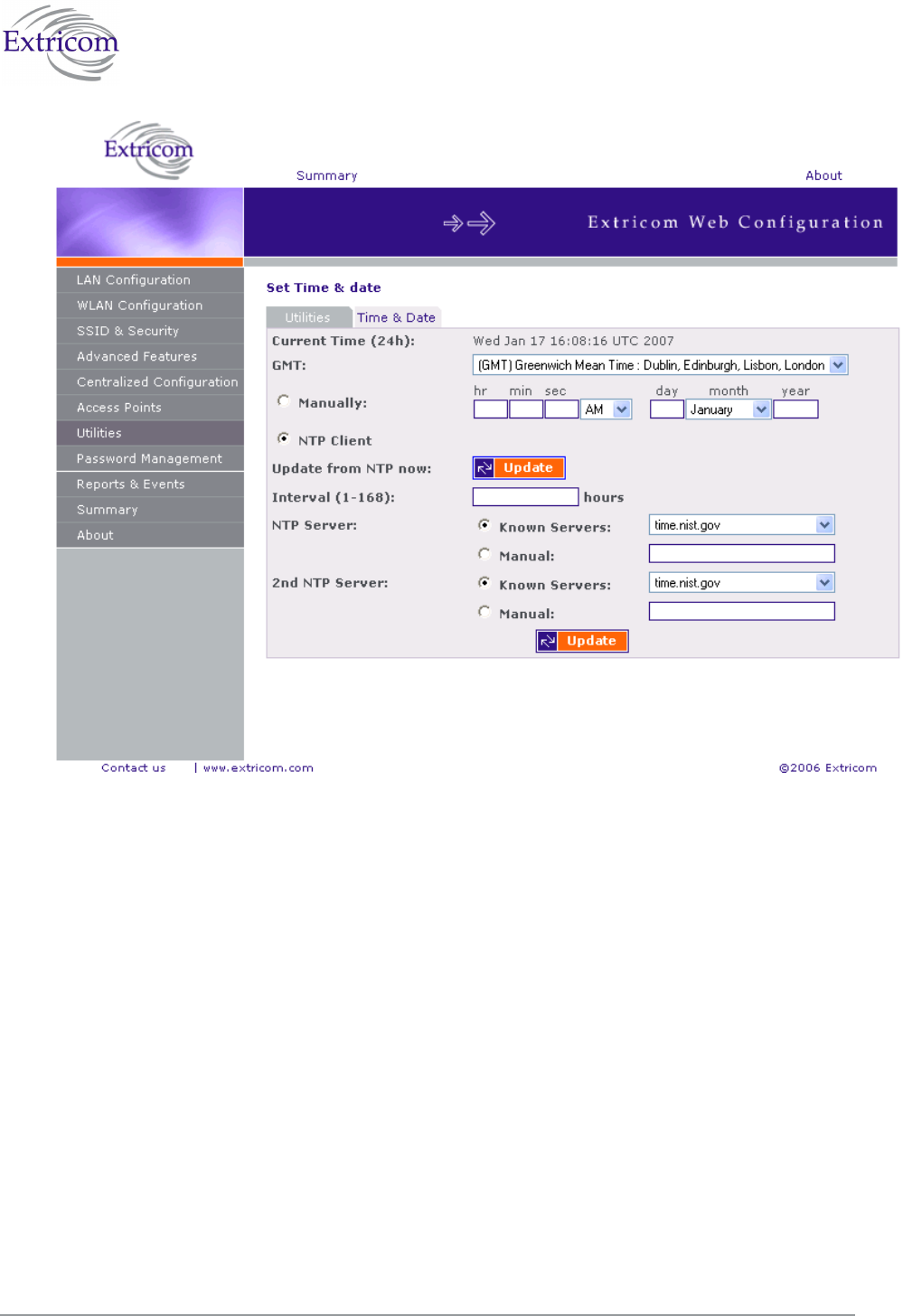
The Extricom WLAN System User Guide 57
Figure 35. Setting Date and Time

58 Configuring the Extricom WLAN System
Setting Passwords in the Extricom Switch
Passwords are set according to user levels. Refer to Table 16 for a description of the user access
levels and their default passwords.
Table 16. Default Passwords
User Access
Level
Privileges Default
Password
admin Accessing the Web configuration. Switch1
The “operator” and “root” passwords are used when accessing the switch for
maintenance and service purposes. Changing these passwords should be performed
only by an Engineer authorized by Extricom.
!
For security purposes, it is important that all the passwords (including operator
and root passwords) be changed from the default values when the switch is first
installed, as well as periodically updated.
!
Record all passwords and store them in a safe location.
To set and change a password for the Extricom switch:
1. Click Password Management in the navigation tree to open the Password Management page.
2. Enter the user access level whose password you want to change.
3. Enter the current password.
4. Enter the new password.
5. Re-type the new password.
Viewing Reports and Events Log
The Reports & Events page provides performance reports and list of events.
To view Reports & Events:
1. Click Reports & Events in the navigation tree.
2. Select Reports tab to view TrueReuse performance. The screen is updated every second.
3. Select Events tab to view events. Hit refresh in order to see new events.
The Extricom WLAN System User Guide 59
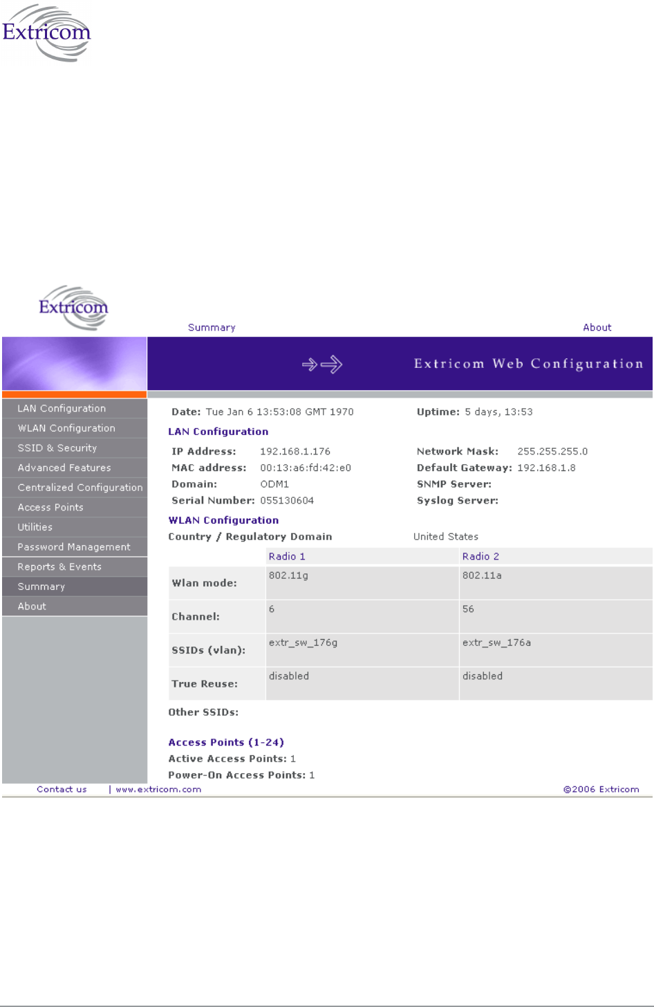
Viewing a Summary of the Updated Configuration
The Summary page provides a summary of the current configuration.
To view a summary of the updated configuration:
1. Click Summary in the navigation tree.
or
Click Summary in the menu bar.
The Summary page appears (refer to Figure 36).
Figure 36. Summary Page
Refer to Table 17 for a description of the summary information.
Table 17. Summary Page

60 Configuring the Extricom WLAN System
Field Description
Date Displays the date and time the summary was created.
Uptime Displays the amount of time the switch has been active.
LAN Configuration
IP Address Displays the IP address of the switch.
MAC address Displays the base MAC address of the switch near the MAC address.
Regulatory
Domain
Displays the regulatory domain name currently in use by the switch.
Network Mask Displays the network mask.
Default Gateway Displays the default gateway IP address.
SNMP Server Displays the IP address of the SNMP server.
Syslog Server Displays the IP address of the syslog server.
WLAN Configuration
Radio 1 Radio 2
Wlan mode
Displays the WLAN mode for
Radio 1
(802.11a, 802.11b, or 802.11g).
Displays the WLAN mode for
Radio 2
(802.11a, 802.11b, or 802.11g).
Channel Displays the channel for Radio 1. Displays the channel for Radio 2.
SSIDs (vlan)
Displays the SSIDs and their
related VLANs, defined and
assigned to Radio 1.
Displays the SSIDs and their
related VLANs, defined and
assigned to Radio 2.
True Reuse Displays TrueReuse status
Other SSIDs Displays other SSIDs that are defined but are not assigned to a
specific Radio.
Access Points (1-8/24)
Active Access
Points
List of the active APs.
Power-On
Access Points
List of APs powered via Power over Ethernet.

The Extricom WLAN System User Guide 61
Viewing Extricom Information
Information about firmware versions currently installed in the Extricom Wireless LAN system can
be viewed in the About page.
To view Extricom information:
Click About in the navigation tree.
or
Click About in the menu bar.
The About page appears.

The Extricom WLAN System User Guide 63
Chapter 4
Troubleshooting
Table 18 lists possible problems you may encounter with your WLAN and provides possible
solutions. If after trying the solutions you are still experiencing difficulties, contact Extricom
Customer Support.
Table 18. Troubleshooting
Problem Solution
The AP Power LED
is not lit.
Verify that the AP Ethernet cable is connected to the switch and to
the AP. The APs get PoE from the switch.
Verify that the AP is not turned off in the Access Points Web
configuration page (refer to page 63).
A wireless device
can’t associate a
specific SSID
Verify that the wireless device supports the same 802.11 standard
as configured for the SSID (802.11/a/b/g).
Verify that the wireless device is set to connect to the specific
SSID.
Verify that the wireless device supports the security standard used
by the SSID, e.g., WEP.
Verify that the security settings are configured to use the same
authentication method.
If the Radius Server is used, verify that the wireless device is
registered and has the necessary authorization.
Cannot connect to
the Extricom web
configuration pages
Verify that the switch is connected to the LAN.
Verify that the correct IP address is used.
Low data rates
Verify that the switch was not mistakenly configured to use low
data rates.
Verify that there is no additional cause of interference (e.g., an
additional WLAN network in the same proximity using the same
frequencies as the Extricom WLAN, or that there are no cordless
phones using the same frequencies, or microwave oven
interference).

64 Troubleshooting
Problem Solution
Wireless devices
disconnect in a
specific location
Verify that there is no additional cause of interference (e.g., an
additional WLAN network in the same proximity using the same
frequencies as the Extricom WLAN, or that there are no cordless
phones using the same frequencies, or microwave oven
interference).
Add an additional AP to cover the area. Plug another AP into the
switch, or relocate an existing Access Point.
Cannot access the
switch’s Web
configuration GUI
Verify that the workstation on which the Web browser is running is
connected to the same LAN as the switch.
Verify that the URL entered for the switch begins with https.

The Extricom WLAN System User Guide 65
Appendix A
Specifications
Extricom Switch Specifications
Standards
WLAN IEEE 802.11a, 5GHz
IEEE 802.11b, 2.4GHz (short/long preamble support)
IEEE 802.11g, 2.4GHz (pure mode)
IEEE 802.11b/g, 2.4GHz (mixed mode)
IEEE 802.11d
Ethernet IEEE 802.3x, full/half duplex
IEEE 802.1q, VLAN tagging
Interfaces
APs
EXSW-2400 – 24x 100BaseT Ethernet with IEEE 802.3af PoE
(out of band)
EXSW-1200 – 12x 100BaseT Ethernet with IEEE 802.3af PoE
(out of band)
EXSW800 – 8x 100BaseT Ethernet with IEEE 802.3af PoE
(out of band)
EXSW-8000 - Recommended SFP modules:
Optech OP6C-MX5-85-C
Wired LAN
EXSW-1200/2400 – 2x 1000/100BaseT Ethernet
EXSW800 – 1x 100/10BaseT Ethernet
EXSW-1600 – GBE - 2x combo ports Copper or Fiber ( no
Mixed allowed)
LAN2 and 1000Mbps are not currently active
pending future development.

66 Specifications
Wireless Performance
Channels Up to 2 simultaneous WLAN channels
Capacity Up to 108Mbps Aggregate WLAN connection-rate (2 channel
blankets, each with 54 Mbps)
Inter-AP handoff 0 ms intra-switch
Management
User Interface Secure Web-based Graphical User Interface (GUI)
SNMP Traps, using SNMP Version 2c
Logging Remote and local SYSLOG
Upgrades Firmware upgrade through Web from anywhere in the LAN.
Security
Encryption WEP-64
WEP-128
WPA-TKIP/AES (CCMP)
WPA2-TKIP/AES (CCMP)
Authentication 802.1x (RADIUS)
WPA/WPA2 pre-shared key
MAC Address-based ACL
EAP, TLS, TTLS, LEAP, PEAP, MD5
SSID & VLAN
SSID 16 SSIDs per channel (maximum of 32 per system)
VLANs 4095 Ethernet VLANs
SSID to VLAN mapping
Regulations Approval
Safety UL 60950-1
EN 60950-1
IEC 60950-1
ANATEL Resolution 237
EMC FCC Part 15 Class B
EN 300386 Part B
VCCI Technical Requirements, V-3/2001.04
ANATEL Resolution 238
Physical Properties
Installation options Rackmount (19" 1U)
Desktop

The Extricom WLAN System User Guide 67
LEDs Power
LAN Activity
WLAN Port Activity
Power EXSW800: 100-240VAC ,50-60Hz, 2A max
EXSW-1200/2400: 100-240VAC ,50-60Hz, 5A max
EXSW-8000: 100-240VAC ,50-60Hz, 3A max
PoE (IEEE 802.3af) to WLAN ports: 15W for each port
Environmental
Operational Temperature: 0°C to 45°C (32°F to 122°F)
Humidity: 0% to 90%, non-condensing
Storage Temperature: - 20°C to +70°C (-49°F to 185°F)
Humidity: 0% to 90%, non-condensing
Extricom Access Point Specifications
WLAN Standards
IEEE 802.11a, 5GHz
IEEE 802.11b, 2.4GHz (short/long preamble support)
IEEE 802.11g, 2.4GHz (pure mode)
IEEE 802.11b/g, 2.4GHz (mixed mode)
Spectrum
Number of simultaneous
channels
Up to two in EXRP-20 and up to four in EXRP-40
In the current release of EXRP-40, Radios 3 and 4
are inactive.
802.11a 5.15-5.25 GHz
5.25-5.35 GHz
5.505-5.725 GHz
5.725-5.850 GHz
Available channels limited by local regulation
802.11b 2.400-2.497 GHz
Available channels limited by local regulation
802.11g 2.400-2.483 GHz
Available channels limited by local regulation
Transmission Power
802.11a Max: 17 dBm (limited by local regulation)
802.11b Max: 17 dBm

68 Specifications
802.11g Max: 15 dBm
Supported Rates
802.11a 6, 9, 12, 18, 24, 36, 48 and 54 Mbps
802.11g 6, 9, 12, 18, 24, 36, 48 and 54 Mbps
802.11b 1, 2, 5.5, and 11 Mbps
Receive Sensitivity
802.11a: 6 Mbps: -88 dBm
9 Mbps: -87 dBm
12 Mbps: -86 dBm
18 Mbps: -84 dBm
24 Mbps: -81 dBm
36 Mbps: -77 dBm
48 Mbps: -73 dBm
54 Mbps: -69 dBm
802.11b/g 1 Mbps: -91 dBm
2 Mbps: -88 dBm
5.5 Mbps: -87 dBm
11 Mbps: -85 dBm
6 Mbps: -89 dBm
9 Mbps: -88 dBm
12 Mbps: -87 dBm
18 Mbps: -85 dBm
24 Mbps: -82 dBm
36 Mbps: -79 dBm
48 Mbps: -74 dBm
54 Mbps: -71 dBm
Regulations Approval
Safety UL 60950
EN 60950
IEC 60950
EMC FCC Part 15 sub part B
EN 301
EN 300328
EN 300440
ENV 301893
EN 300386 Part B
VCCI V-2/2001.04

The Extricom WLAN System User Guide 69
Access
(including modular
approval)
FCC Part 15 C
FCC Part 15 E
EN 300 328
EN 301 893
EN 300 489
Japan Type Certificate: Article 2, clause 1, Items 19, 19-2, 19-3,
19-13
Physical Properties
Dimensions (W x H x D) 195mm x 150mm x 50mm (7.67" x 5.9" x 2")
Weight 400gr (0.8 lb.)
Installation options Horizontal (desktop)
Vertical (wall mount)
LEDs Power
LAN Activity
2 x WLAN Activity (2 colors)
Power PoE (IEEE 802.3af): 15W
Power Supply (optional): 48VDC @ 400mA
Environmental
Operational Temperature: 0°C to 45°C (32°F to 122°F)
Humidity: 0% to 90%, non-condensing
Storage Temperature: - 20°C to +70°C (-49°F to 185°F)
Humidity: 0% to 90%, non-condensing
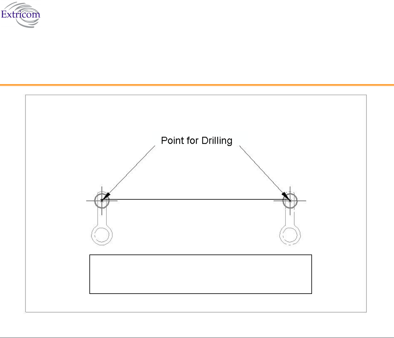
The Extricom WLAN System User Guide 70
Appendix B
Access Point Mounting Template
Figure 37. Access Point Mounting Template
4.25 inches
10.7
cm.
Important Note: Due to variations in printers, when printing this page,
printer Page Scaling should be set to “None” or diagram may be
automatically reduced in size. As a double-check, make sure distance
between drill points is as indicated above.

The Extricom WLAN System User Guide 71