Ezurio 01B The Intelligent Bluetooth Serial Module Version II User Manual BISM2 Data Sheet v0 9
Ezurio Ltd The Intelligent Bluetooth Serial Module Version II BISM2 Data Sheet v0 9
Ezurio >
Contents
- 1. User Guide
- 2. Users Manual
- 3. User Manual
User Guide
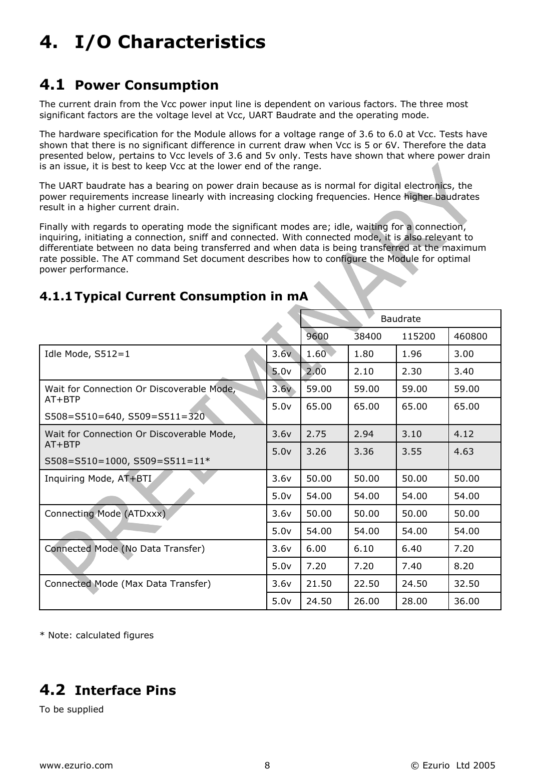
![www.ezurio.com © Ezurio Ltd 2005 12 6.1.2 SPI bus The Module is a slave device that uses terminals SPI_MOSI, SPI_MISO, SPI_CLK and SPI_CSB. This interface is used for program firmware update. Note: The designer should be aware that no security protection is built into the hardware or firmware associated with this port, so the terminals should not be permanently connected in a PC application. 6.1.3 GPIO Port Eight lines of programmable bi-directional input/outputs (I/O) are provided that can be accessed either via the UART port, or Over The Air from a second Bluetooth unit. These can be used as data inputs or to control external equipment. By using these in OTA mode, a BISM21 module can be used for control and data acquisition without the need for any additional host processor. Each of the GPIO[1:8] ports can be independently configured to be either an Input or Output. A selection of ports can be accessed synchronously. GPIO 1 and 2 can be configured as event counters. The ports are powered from VCC. The mode of these lines can be configured and the lines are accessed via S Registers 621 to 625. Low latency I/O can be accessed by using Ezurio’s I/O via enquiry process. 6.1.4 PCM CODEC Interface PCM_OUT, PCM_IN, PCM_CLK and PCM_SYNC carry up to three bi-directional channels of voice data, each at 8ksamples/s. The format of the PCM samples can be 8-bit A-law, 8-bit µ-law, 13-bit linear or 16-bit linear. The PCM_CLK and PCM_SYNC terminals can be configured as inputs or outputs, depending on whether the module is the Master or Slave of the PCM interface. The Module is compatible with the Motorola SSI TM interface and interfaces directly to PCM audio devices including the following: 6.1.4.1 Compatible Codec Chips • Qualcomm MSM 3000 series and MSM 5000 series CDMA baseband devices • OKI MSM7705 four channel A-law and µ-law CODEC • Motorola MC145481 8-bit A-law and µ-law CODEC • Motorola MC145483 13-bit linear CODEC 6.1.5 ADC The BISM2 provides access to two 8-bit ADCs are available. These provide a range o 0mV to 1,800mV, which can be read using the S registers 701 and 702. Suitable external scaling and over-voltage protection should be incorporated in your design. 6.1.6 Pass Through Serial To be supplied](https://usermanual.wiki/Ezurio/01B.User-Guide/User-Guide-565453-Page-12.png)