Ezurio 06WITS Wireless Intelligent Telematics System (WITS) User Manual Users manual
Ezurio Ltd Wireless Intelligent Telematics System (WITS) Users manual
Ezurio >
Users manual

© Ezurio Ltd 2007
WITS Installation Guide
Doc No:
VEHIU-R-020 Issue No :
1.3
Date :
24 August 2007 Page i
Author :
Tim Wheatley
WITS Installation Guide
Prepared by :
Tim Wheatley
Authorised by:
Chris Shannon
Signature : Signature :
© 2007 COPYRIGHT Ezurio Ltd
This document is issued by Ezurio Limited (hereinafter called Ezurio) in confidence, and is not to be
reproduced in whole or in part without the prior written permission of Ezurio. The information contained
herein is the property of Ezurio and is to be used only for the purpose for which it is submitted and is not to
be released in whole or in part without the prior written permission of Ezurio.

WITS Installation Guide
Doc No :
VEHIU-R-020 Page ii
© Ezurio Ltd 2007 VEHIU-R-020-01 Installation Guide.doc1
2
Change History
Issue Change Author Date
1.0 First version Tim Wheatley 4/04/2007
1.1 Updated for revision 1.0 hardware Julian King 11/07/2007
1.2 Clarification of external WiFi antenna Julian King 23/08/2007
1.3 Addition of FCC Radiation Statement & Bluetooth FCC ID Julian King 24/08/2007

© Ezurio Ltd 2007
WITS Installation Guide
Doc No:
VEHIU-R-020 Issue No :
1.3
Date :
24 August 2007 Page i
WITS Installation Guide
© 2007 COPYRIGHT Ezurio Ltd
This document is issued by Ezurio Limited (hereinafter called Ezurio) in confidence, and is not to be
reproduced in whole or in part without the prior written permission of Ezurio. The information contained
herein is the property of Ezurio and is to be used only for the purpose for which it is submitted and is not to
be released in whole or in part without the prior written permission of Ezurio.
Contents

WITS Installation Guide
Doc No :
VEHIU-R-020 Page 2 of 22
© Ezurio Ltd 2007 VEHIU-R-020-01 Installation Guide.doc1
2
1. Safety & Regulatory Statements 3
1.1 FCC Regulatory Statement ............................................................................................ 3
2. Introduction. 4
2.1 Deliverable Contents...................................................................................................... 4
3. Configuring Units Before Use 5
4. Logging and Reporting 10
4.1 Logging .......................................................................................................................... 10
4.2 Reporting ....................................................................................................................... 10
4.3 External Wireless LAN Antenna ..................................................................................... 10
5. Accessing Logged Data 11
6. Updating the Script 14
7. Updating Firmware 16
7.1 Fault Finding .................................................................................................................. 20

WITS Installation Guide
Doc No :
VEHIU-R-020 Page 3 of 22
© Ezurio Ltd 2007 VEHIU-R-020-01 Installation Guide.doc1
3
1. Safety & Regulatory Statements
1.1 FCC Regulatory Statement
This device complies with Part 15 of the FCC Rules. Operation is subject to the following two
conditions: (1) This device may not cause harmful interference, and (2) This device must accept
any interference received, including interference that may cause undesired operation.
Changes or modifications not expressly approved by the party responsible for compliance could
void the user’s authority to operate this equipment.
1.2 FCC Radiation Exposure Statement
This equipment complies with FCC RF radiation exposure limits set forth for an uncontrolled
environment. The antenna(s) used for this transmitter must be installed to provide a separation
distance of at least 20 cm from all persons and must not be co-located or operating in
conjunction with any other antenna or transmitter.
1.3 Included Approved Devices
This equipment includes a pre-approved Bluetooth module, FCC ID PI403B.

WITS Installation Guide
Doc No :
VEHIU-R-020 Page 4 of 22
© Ezurio Ltd 2007 VEHIU-R-020-01 Installation Guide.doc1
4
2. Introduction.
This document provides an installation and user guide for the WITS vehicle data logging unit.
2.1 Deliverable Contents
The WITS deliverable package consists of the following hardware items:
• 1 off WITS vehicle data logger unit
• 1 off USB cable, ‘A’ to ‘Mini B’
• 1 off GPS antenna, SMA connector
• 1 off OBD connector cable
• 1 off External WiFi antenna (Optional)
The following software is provided on the included CD:
• UwTerminal.exe. This is a terminal emulation program that has a number of Ezurio
specific extensions. This program should be used to communicate with the modules for
configuration or debug purposes.
• UWLoad.exe. This utility is used to upload new firmware images into the units.
• CDM 2.00.00 x64.zip. Contains the PC driver needed to interface to the prototype units.
WITS Installation Guide
Doc No :
VEHIU-R-020 Page 5 of 22
© Ezurio Ltd 2007 VEHIU-R-020-01 Installation Guide.doc1
5
3. Configuring Units Before Use
The WITS unit is supplied with the GPS antenna connected and attached to the unit and will be
pre-configured with all of the essential information to allow access to the Ezurio middleware
server. All that the installer needs to do is to configure the SSID (and optional WEP key) of the
access point that will be used to provide wireless access to the internet.
To configure the unit follow these steps:
i) Load the supplied CD into a PC and copy the UWTerminal.exe and UWLoad.exe
utilities to a suitable location.
ii) Plug the unit into the PC using the USB cable supplied.
iii) If the PC requests a driver for the hardware, then this is available on the CD. The unit
communicates using a virtual COM port.
iv) Once the driver is installed and the hardware is ready for use, the next step is to
identify the COM port needed to communicate with the unit. This can be identified by
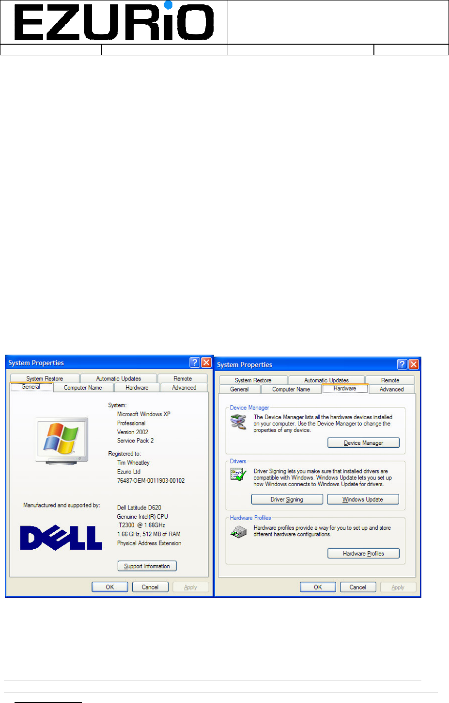
looking at the system properties by right clicking on the ‘My Computer’ icon and
selecting properties. This will display the system properties screen. Select the
‘Hardware’ tab and then select ‘Device Manager’. In that screen open the ‘Ports
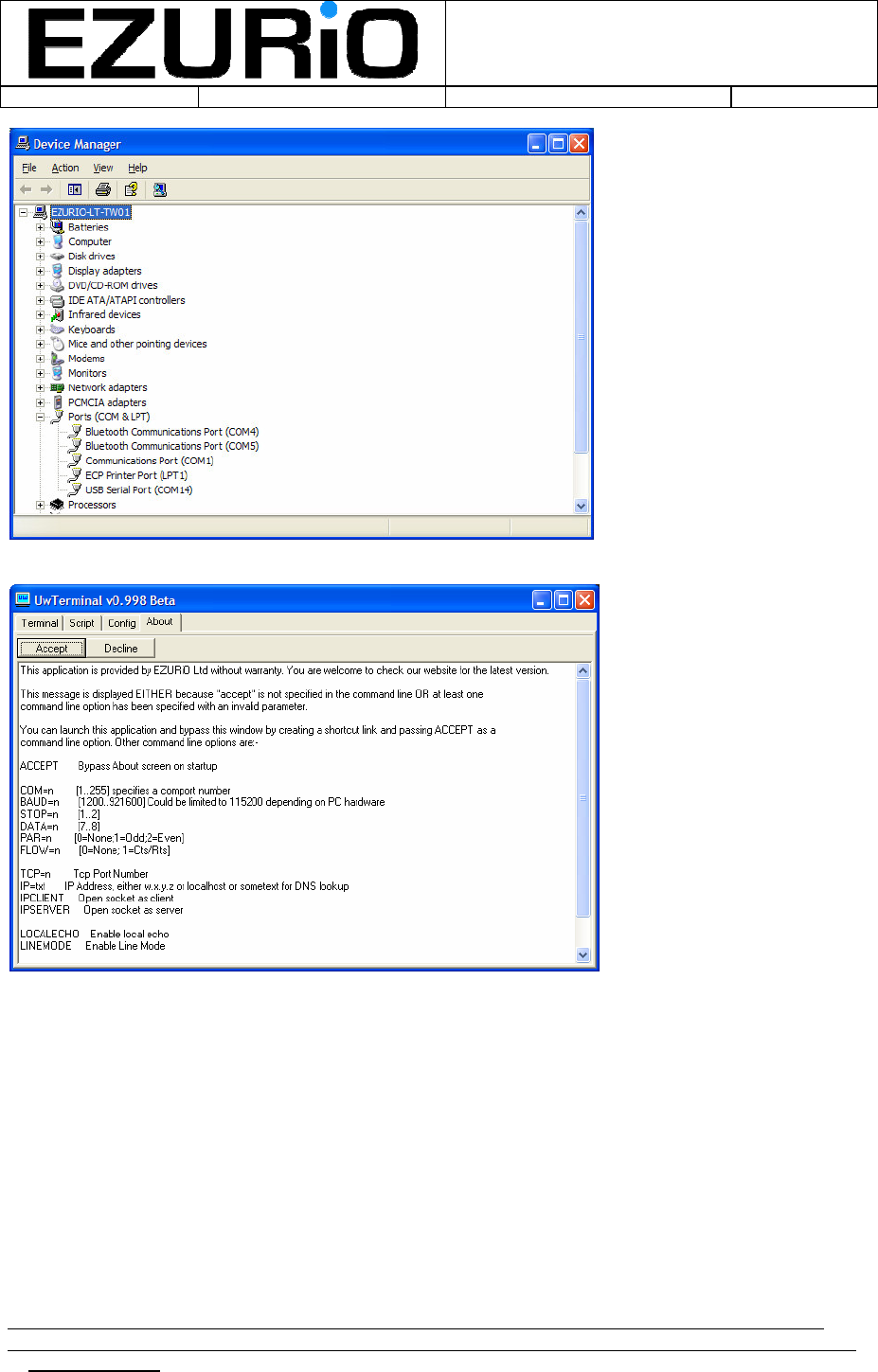
(COM & LPT)’ heading and all of the COM ports available in the PC will be displayed.
The unit will show up as a USB Serial Port. In the example below it is COM14.
WITS Installation Guide
Doc No :
VEHIU-R-020 Page 6 of 22
© Ezurio Ltd 2007 VEHIU-R-020-01 Installation Guide.doc1
6
v) Run the UWTerminal.exe executable. The following screen will be displayed:
Select Accept and the following screen is displayed:
WITS Installation Guide
Doc No :
VEHIU-R-020 Page 7 of 22
© Ezurio Ltd 2007 VEHIU-R-020-01 Installation Guide.doc1
7
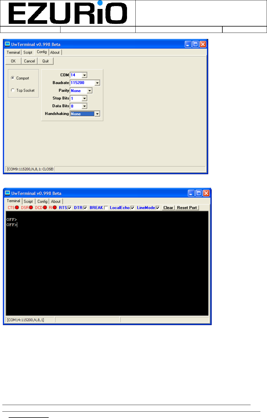
Select the correct COM port from the COM pull down and press OK. Push the Enter key a
couple of times and the OFF> prompt will be displayed:
v) Enter the command ‘start 4’ (case sensitive) and the prompt will change:
WITS Installation Guide
Doc No :
VEHIU-R-020 Page 8 of 22
© Ezurio Ltd 2007 VEHIU-R-020-01 Installation Guide.doc1
8
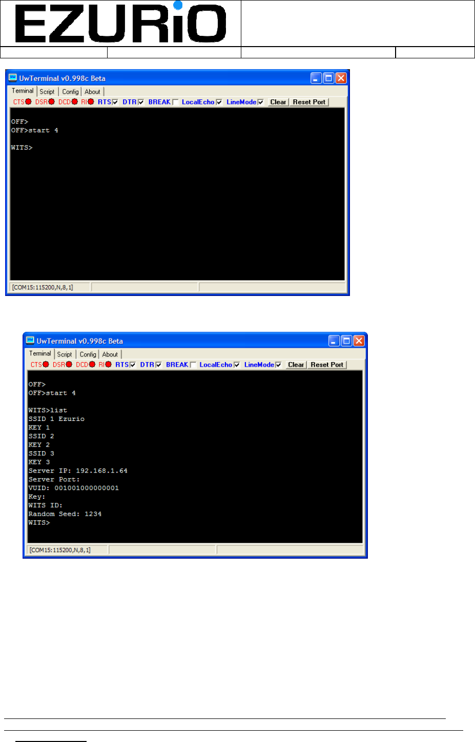
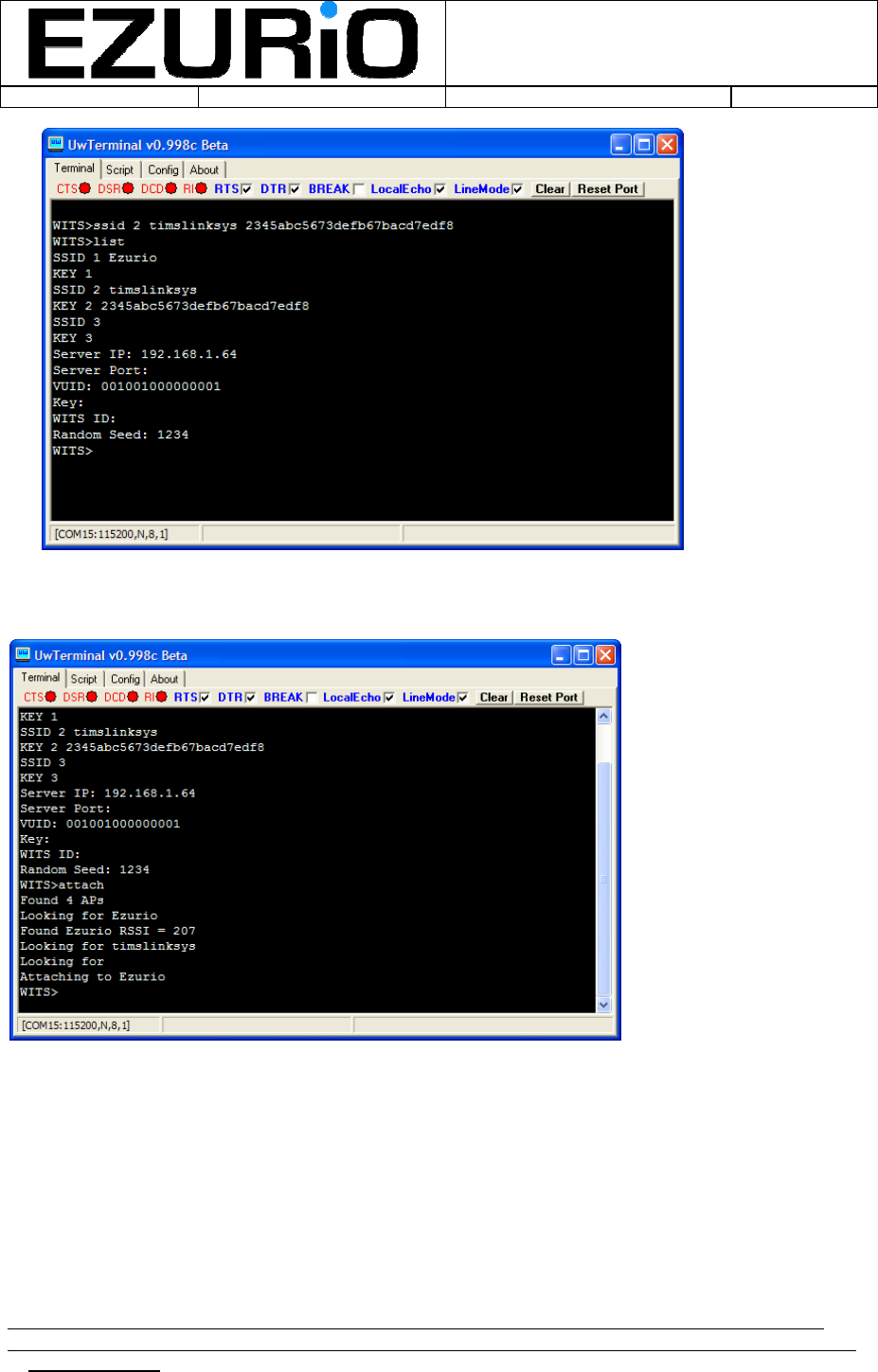
vi) At the WITS> prompt type the command ‘list’ and this will display the current non-
volatile settings for the unit:
The server ip, VUID and random seed parameters should not be changed.
vii) Up to 3 access points can be programmed into the system. To enter an SSID use the
command ‘ssid n SSIDName keydigits’ where n is between 1 and 3 and SSIDName is
the name of the AP and keydigits is the WEP key (if required). The following screen
shows an example of the ssid command
WITS Installation Guide
Doc No :
VEHIU-R-020 Page 9 of 22
© Ezurio Ltd 2007 VEHIU-R-020-01 Installation Guide.doc1
9
To test the SSID settings, the ‘attach’ command may be used. This scans for available access
points in the list and will attach to the access point that has the strongest signal strength. The
screen below shows a demonstration of the attach command:
Once the access points have been configured and tested, the configuration is complete. To
complete the session, type ‘quit’ and the unit will switch off and be ready for installation in the
vehicle.
Once the unit is disconnected from the PC it should be plugged into the vehicle OBD port (this is
not essential as the in-built battery should have sufficient capacity to allow logging for a
reasonable period) from which it derives power.

WITS Installation Guide
Doc No :
VEHIU-R-020 Page 10 of 22
© Ezurio Ltd 2007 VEHIU-R-020-01 Installation Guide.doc1
10
4. Logging and Reporting
The WITS unit monitors the state of the vehicle ignition and automatically switches between
logging and reporting modes.
4.1 Logging
When the vehicle ignition is switched on the unit will start-up automatically and after a short
delay the yellow LED will illuminate and the red LED will flash once per second to indicate
logging is in progress.
When the unit is logging, the status of the GPS signal is indicated by the colour of the flashing
LED. When the GPS signal is invalid the LED will flash red and when the GPS signal is valid, the
LED will flash green. If the LED does not change to green, experiment with another orientation
for the unit so that the GPS antenna has a different view of the sky. Our tests show that most
locations in a vehicle should give sufficient signal for the GPS to operate – but there may be
locations where this is not the case.
4.2 Reporting
When the vehicle ignition is switched off the unit will detect that the journey is complete or
interrupted and will shutdown automatically. If the unit determines that logging data should be
reported it will automatically start-up after a short delay (5-10 seconds). When the unit
successfully connects to the wireless LAN access point, the blue LED will illuminate for the
duration of the data upload to the server. If the unit cannot find the access point, or if the report
fails for some reason then the red LED will illuminate for 5 seconds and then the unit will switch
off. If the report is completed successfully, the green LED will illuminate for 5 seconds before the
unit switches off.
4.3 External Wireless LAN Antenna
If reporting is unreliable or impossible it may be necessary to use an external antenna to improve the
performance of the Wireless LAN. As an option a 3dBi dipole external antenna is available for this product.
Under no circumstances should any antenna other than one supplied by Ezurio Limited expressly for the
WITS product be used with this unit. The unit utilises a special reverse SMA connector to prevent use of
incorrect antennas.
WITS Installation Guide
Doc No :
VEHIU-R-020 Page 11 of 22
© Ezurio Ltd 2007 VEHIU-R-020-01 Installation Guide.doc1
11
5. Accessing Logged Data
When logged data has been reported back to the middleware, it is ready to be accessed from
the database. A simple user interface has been developed to provide access to logged data
reports.
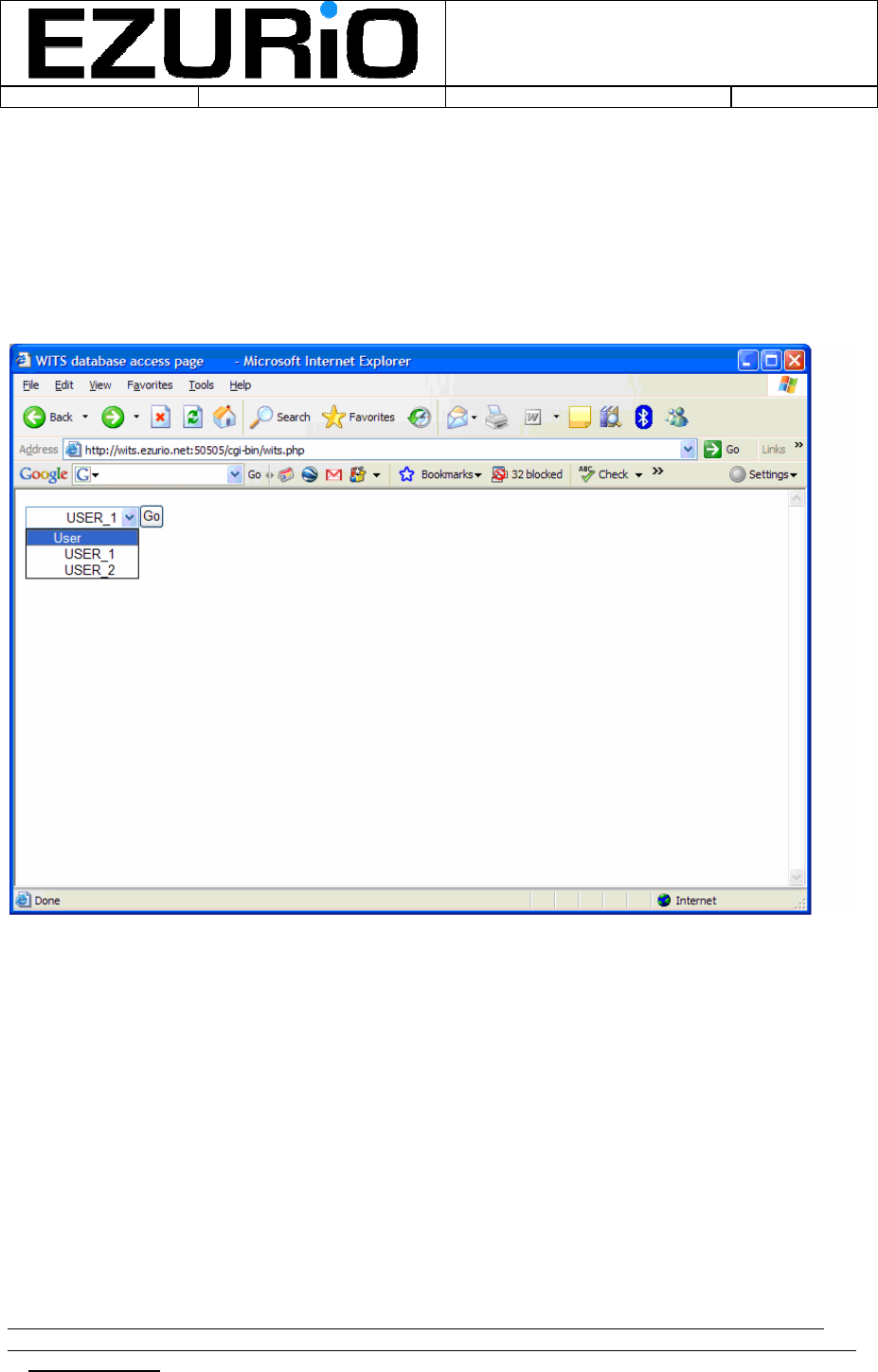
The supplied documentation will indicate the URL of the first page of the user interface, which
will look like:
The pull down menu allows access to all registered users of the system. Select the user required
and select ‘Go’. The following screen is then displayed:
WITS Installation Guide
Doc No :
VEHIU-R-020 Page 12 of 22
© Ezurio Ltd 2007 VEHIU-R-020-01 Installation Guide.doc1
12
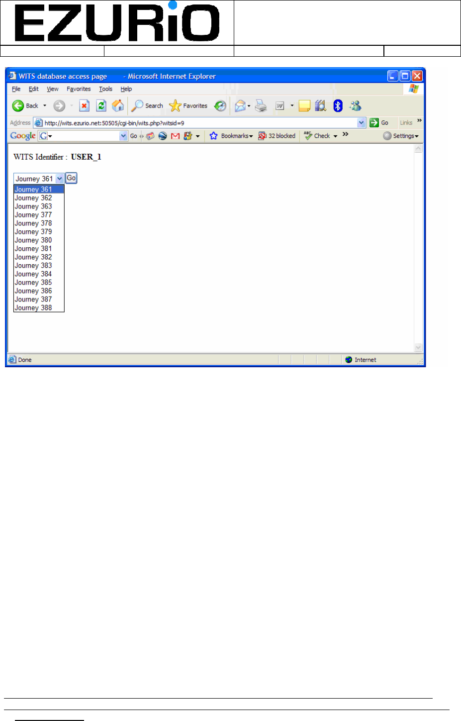
This screen allows the user to select a particular journey to view. A journey is defined as one
logging session. Simply select the required journey and the data will be displayed as shown
below:
WITS Installation Guide
Doc No :
VEHIU-R-020 Page 13 of 22
© Ezurio Ltd 2007 VEHIU-R-020-01 Installation Guide.doc1
13
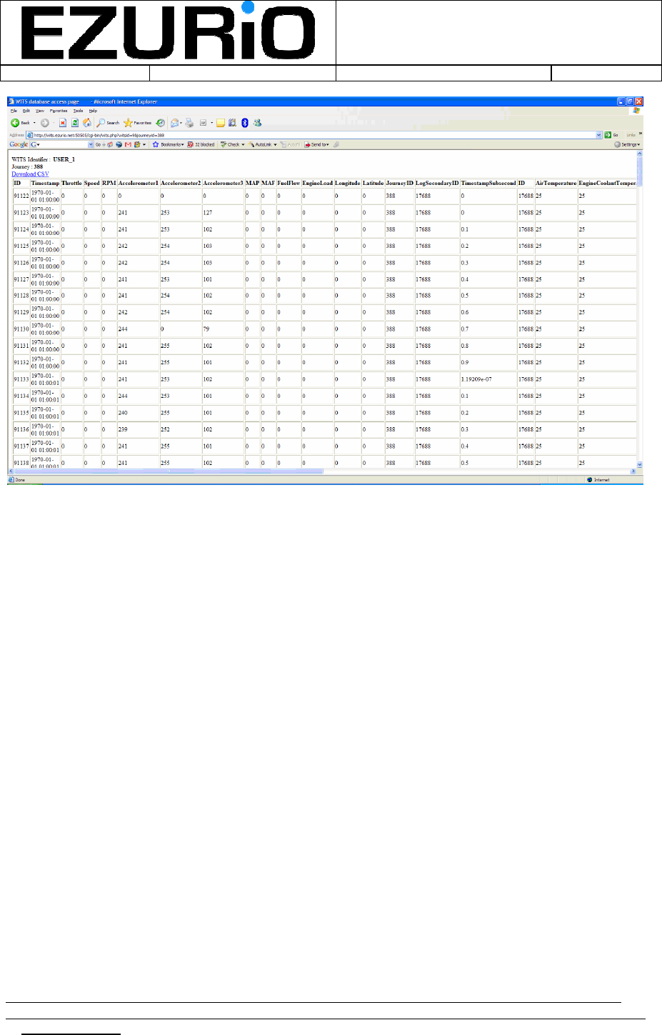
NB Position is only displayed when the GPS signal is valid.
If a CSV file containing the data for the journey is required, then simply select the ‘Download
CSV’ option
WITS Installation Guide
Doc No :
VEHIU-R-020 Page 14 of 22
© Ezurio Ltd 2007 VEHIU-R-020-01 Installation Guide.doc1
14
6. Updating the Script
The logging operations of the unit are controlled by a script that allows all aspects of the logging
process to be flexibly controlled. Normally new control scripts will be downloaded by the
middleware when required, however, it may be necessary in certain cases for a new script to be
updated manually using the following process:
Firstly, follow the instructions in Section 2 for configuring the unit, but stop before entering the
‘Start 4’ command. Instead, enter the command ‘quit’. This will stop the current script from
operating.
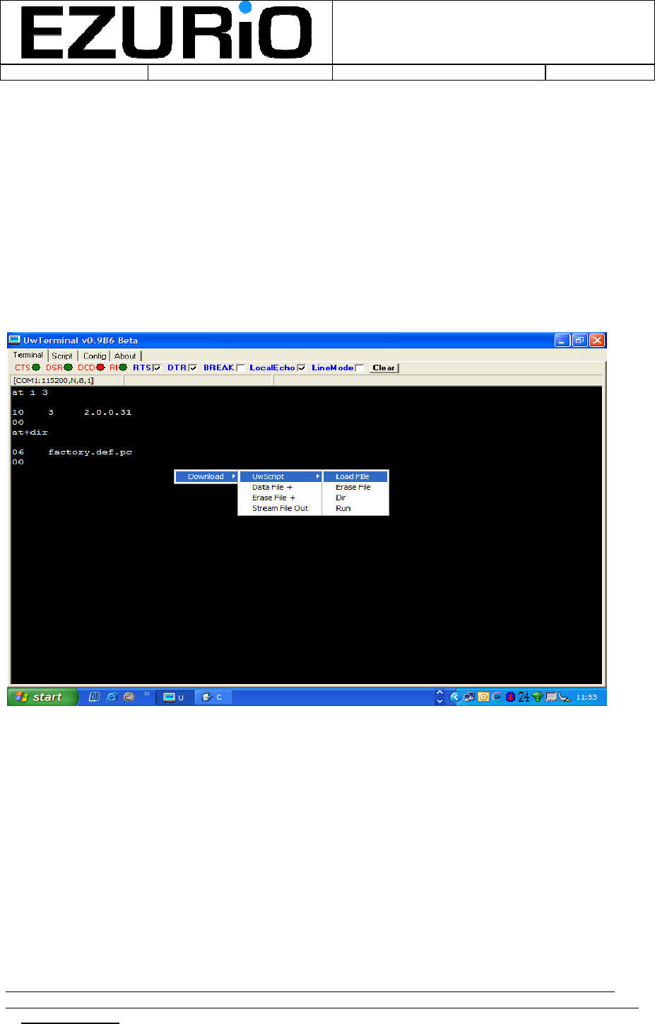
To load a user script, right click anywhere in the terminal window and then follow the menu
structure, as follows:
The following options are available for script management:
• Load File: Brings up a file selection window to allow the user to select the file to
download. When file is selected this is automatically downloaded to the module. If the
script is already in the module memory, then it is deleted and the new script will replace
it. Using this option is equivalent to using the following interactive commands:
at+del “scriptname”
at+cmp “scriptname”
• Erase File: Brings up a file selection window. When the script is selected, the module will
check if it is memory and, if so, delete it. This is equivalent to the following interactive
command:
at+del “scriptname”

WITS Installation Guide
Doc No :
VEHIU-R-020 Page 15 of 22
© Ezurio Ltd 2007 VEHIU-R-020-01 Installation Guide.doc1
15
• Dir: Displays the current scripts and data files stored in the module memory. This is
equivalent to the following interactive command:
at+dir
• Run: Brings up a file selection window. When the script is selected, the module will check
if it is memory and, if so, run it. This is equivalent to the following interactive command:
at+run “scriptname”
WITS Installation Guide
Doc No :
VEHIU-R-020 Page 16 of 22
© Ezurio Ltd 2007 VEHIU-R-020-01 Installation Guide.doc1
16
7. Updating Firmware
Normally firmware updates are downloaded automatically by the middleware when required,
however, it may be necessary in certain cases for the firmware to be updated manually using the
flash loader as follows:
Before running the flash loader, the flash load header should be plugged into the OBD connector
and the unit reset .
The flash loader utility is supplied in the zip file UWLoad.zip. Both files in this archive should be
unzipped to the same directory.
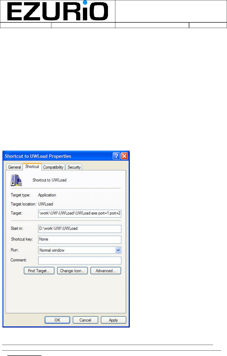
The flash loader can support the parallel programming of up to 10 units and hence up to 10
serial ports can be specified for use with the loader. To specify one or more serial ports, the
COM port number is supplied to the flash loader on the command line. This is most easily done
by placing a shortcut to the flash loader executable on the desktop and then modifying the
command line in the ‘properties’ window for the shortcut (accessed by right clicking on the
shortcut icon). This is shown below for an example where two serial ports are specified.
The port numbers refer to the COM numbers assigned to the serial ports.
WITS Installation Guide
Doc No :
VEHIU-R-020 Page 17 of 22
© Ezurio Ltd 2007 VEHIU-R-020-01 Installation Guide.doc1
17
The ‘Start in’ file location MUST be the same location as the executable.
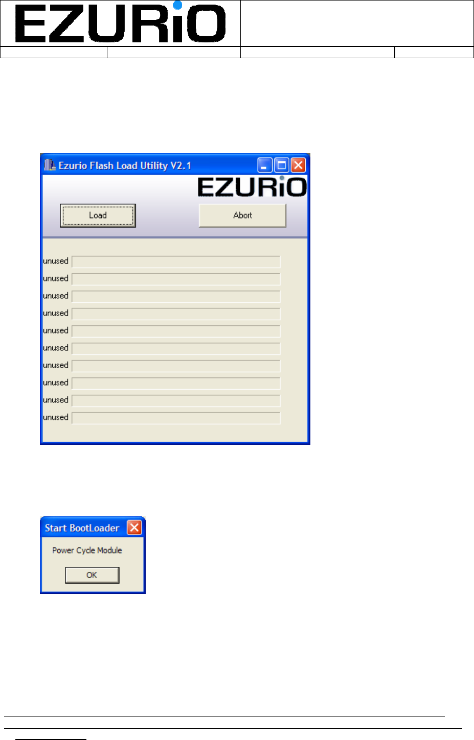
Once the port numbers have been specified, run the flash loader utility and the following screen
is displayed:
Push the ‘Load’ button and a window is displayed prompting the user to power cycle the
module:
Simply push the OK button.
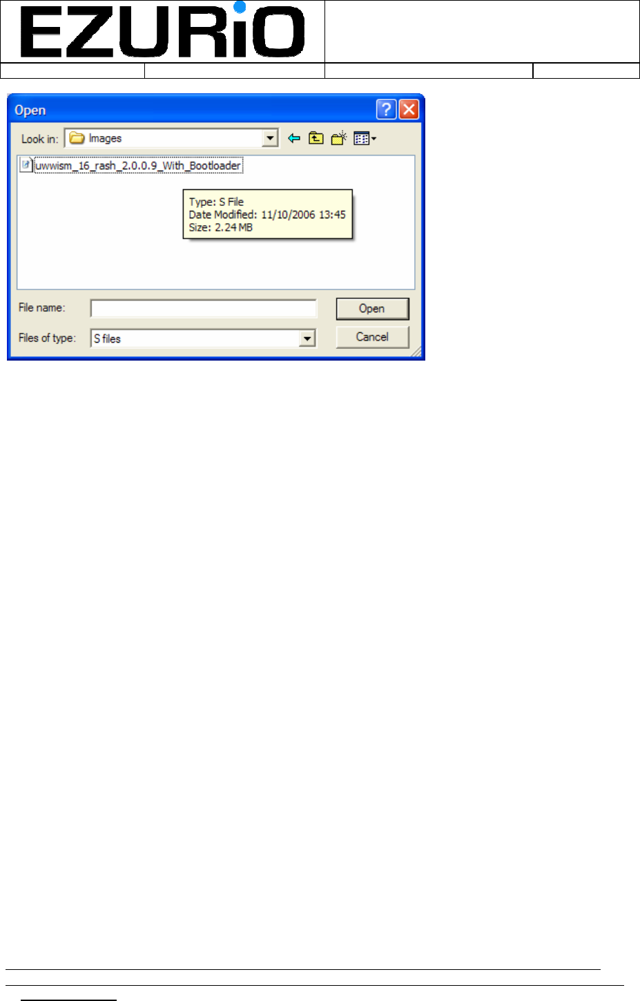
The user is then prompted to select the firmware image to be downloaded:
WITS Installation Guide
Doc No :
VEHIU-R-020 Page 18 of 22
© Ezurio Ltd 2007 VEHIU-R-020-01 Installation Guide.doc1
18
Select the firmware image and press Open. Flash loading will now start. The progress bars for
the active serial ports will then be used to indicate flash progress with each of the modules being
programmed. It is possible that the flash load will fail at the first attempt (the progress bars will
stop moving) – if this happens simply press the abort button and then repeat the above process
starting with pressing the Load button.
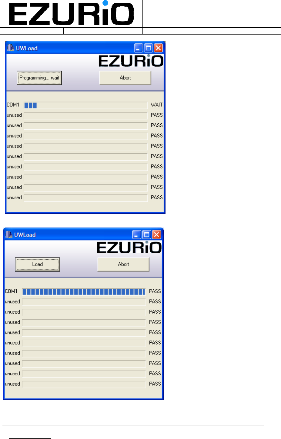
Flash programming occurs in two stages – the first phase is the erase cycle and the progress
bar will indicate the progress through this stage before being erased and then showing the
progress through the second, programming, phase. Whilst programming is in progress, the
status indicator on the right hand side will show WAIT for all active modules. When programming
is complete the status indicator will change to PASS. When all status indicators show pass the
programming operation is complete. A typical window during programming is shown below:
WITS Installation Guide
Doc No :
VEHIU-R-020 Page 19 of 22
© Ezurio Ltd 2007 VEHIU-R-020-01 Installation Guide.doc1
19
When programming is successfully completed the following window is displayed:
WITS Installation Guide
Doc No :
VEHIU-R-020 Page 20 of 22
© Ezurio Ltd 2007 VEHIU-R-020-01 Installation Guide.doc1
20
7.1 Fault Finding
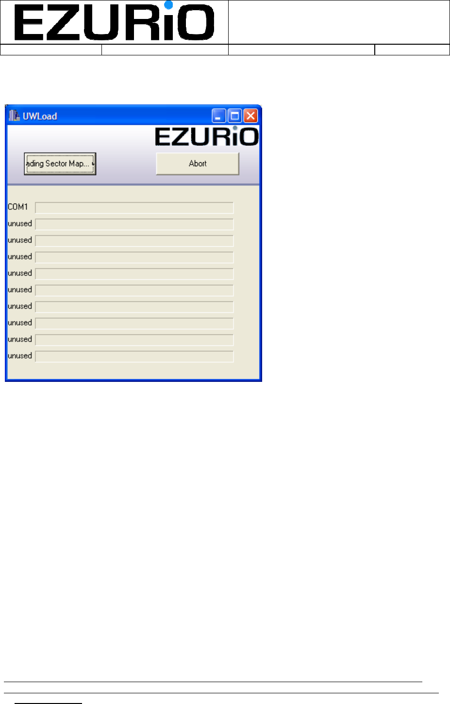
If the following screen is displayed:
This indicates that the SectorMap.ini file cannot be found. This file MUST reside in the same
location as the flash loader executable.
If the load process stops during the erase cycle, it is likely that the module has not been power
cycled or reset when prompted by the program. It is also possible that insufficient time was
allowed after module reset for the module to enter flash loading mode. To resolve this, shut
down the flash loader, re-start it and repeat the process.