Ezurio 07B Bluetooth Intelligent Serial Module Version II User Manual BISM II 3V3 Data Sheet
Ezurio Ltd Bluetooth Intelligent Serial Module Version II BISM II 3V3 Data Sheet
UserManual.wiki
>
Ezurio
>
07B User Manual
User manual
Navigation menu
Upload a User Manual
Namespaces
Wiki Guide
HTML
PDF
Info
Views
User Manual
Discussion / Help
Navigation
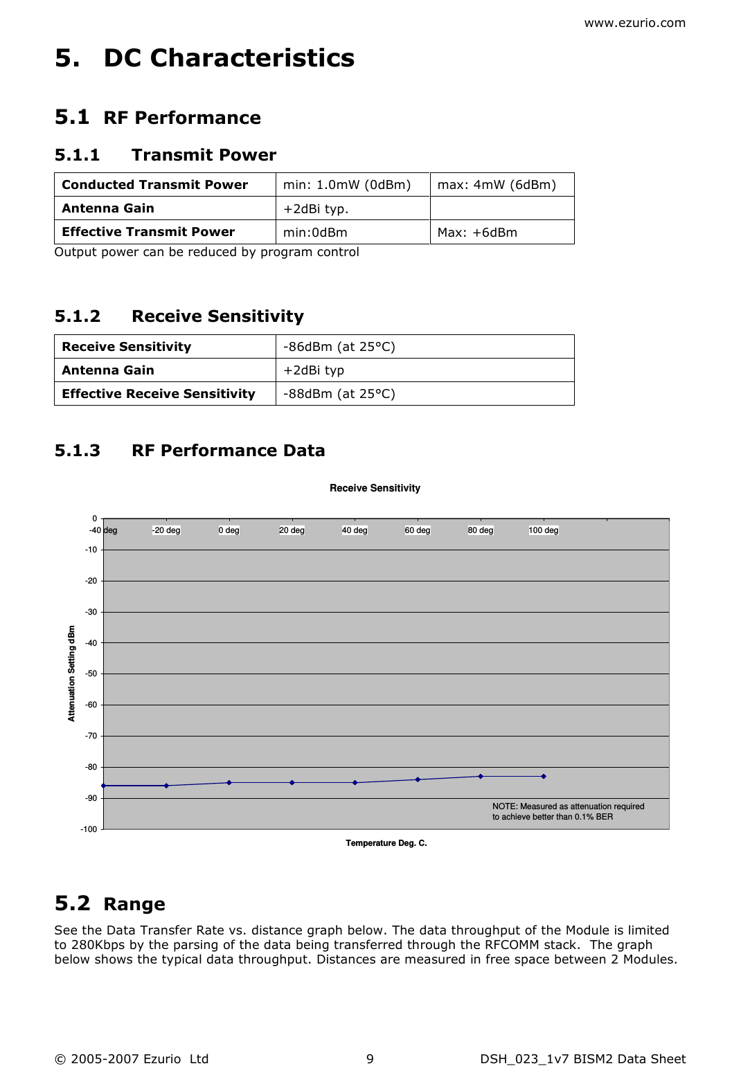
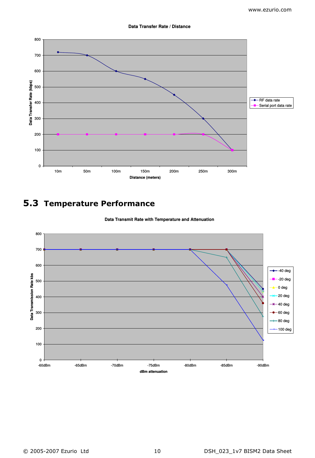
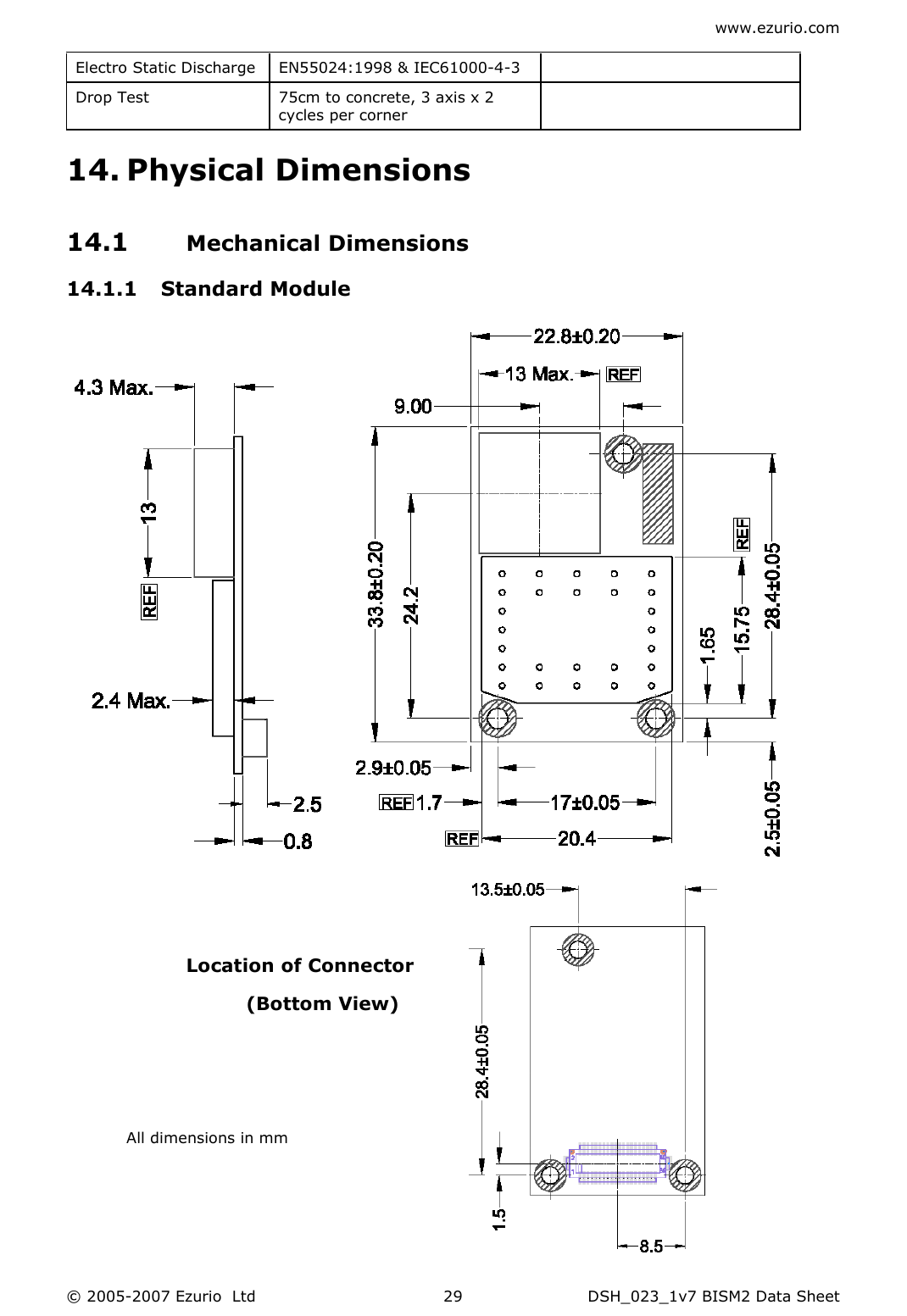
![www.ezurio.com © 2005-2007 Ezurio Ltd DSH_023_1v7 BISM2 Data Sheet 126.1.2 SPI bus The Module is a slave device that uses terminals SPI_MOSI, SPI_MISO, SPI_CLK and SPI_CSB. This interface is used for program firmware updates at the factory. Ezurio supply a PC based utility to allow firmware upgrade over the UART port. It is highly recommended that customers should use this method for updating firmware. Note: The designer should be aware that no security protection is built into the hardware or firmware associated with this port, so the terminals should not be permanently connected in a PC application. 6.1.3 GPIO Port Eight lines of programmable bi-directional input/outputs (I/O) are provided that can be accessed either via the UART port, or Over The Air (OTA) from a second Bluetooth unit. These can be used as data inputs or to control external equipment. By using these in OTA mode, a BISM module can be used for control and data acquisition without the need for any additional host processor. Each of the GPIO[1:8] ports can be independently configured to be either an Input or Output. A selection of ports can be accessed synchronously. GPIO 1 and 2 can be configured as event counters. The ports are powered from VCC. The mode of these lines can be configured and the lines are accessed via S Registers 621 to 628. Low latency I/O can be accessed by using Ezurio’s I/O via an enhanced inquiry process. 6.1.4 PCM CODEC Interface PCM_OUT, PCM_IN, PCM_CLK and PCM_SYNC carry up to three bi-directional channels of voice data, each at 8ksamples/s. The format of the PCM samples can be 8-bit A-law, 8-bit µ-law, 13-bit linear or 16-bit linear. The PCM_CLK and PCM_SYNC terminals can be configured as inputs or outputs, depending on whether the module is the Master or Slave of the PCM interface. Please contact an Ezurio FAE for further details. The Module is compatible with the Motorola SSI TM interface and interfaces directly to PCM audio devices including the following: 6.1.4.1 Compatible Codec Chips • Winbond W61360 13-bit linear CODEC (Motorola MC145483 compatible) • OKI MSM7702 single channel A-law and µ-law CODEC • OKI MSM7705 four channel A-law and µ-law CODEC The default codec support is for the Winbond W61360 Codec development boards that mate with the EZURiO Wireless Developers Kit are available for each of the three codecs listed above. 6.1.5 ADC The BISM2 provides access to two 8-bit ADCs. These provide an input range of 0mV to 1,800mV, which can be read using the S registers 701 and 702. Suitable external scaling and over-voltage protection should be incorporated in your design. The module provides 5 samples per second at the UART with a baud rate of 115200 or above. Low latency access of the upper 6 bits of the ADCs can be obtained by using Ezurio’s I/O via an enhanced inquiry process. 6.1.6 LED A single LED provides information on the status of the module. It is controlled by a S register to display the status of various parameters and is useful for debug and test.](https://usermanual.wiki/Ezurio/07B/User-Guide-888605-Page-12.png)