Ezurio 511B Bluetooth Multimedia Module User Manual
Ezurio Ltd Bluetooth Multimedia Module
UserManual.wiki
>
Ezurio
>
511B User Manual
User Manual
Navigation menu
Upload a User Manual
Namespaces
Wiki Guide
HTML
PDF
Info
Views
User Manual
Discussion / Help
Navigation


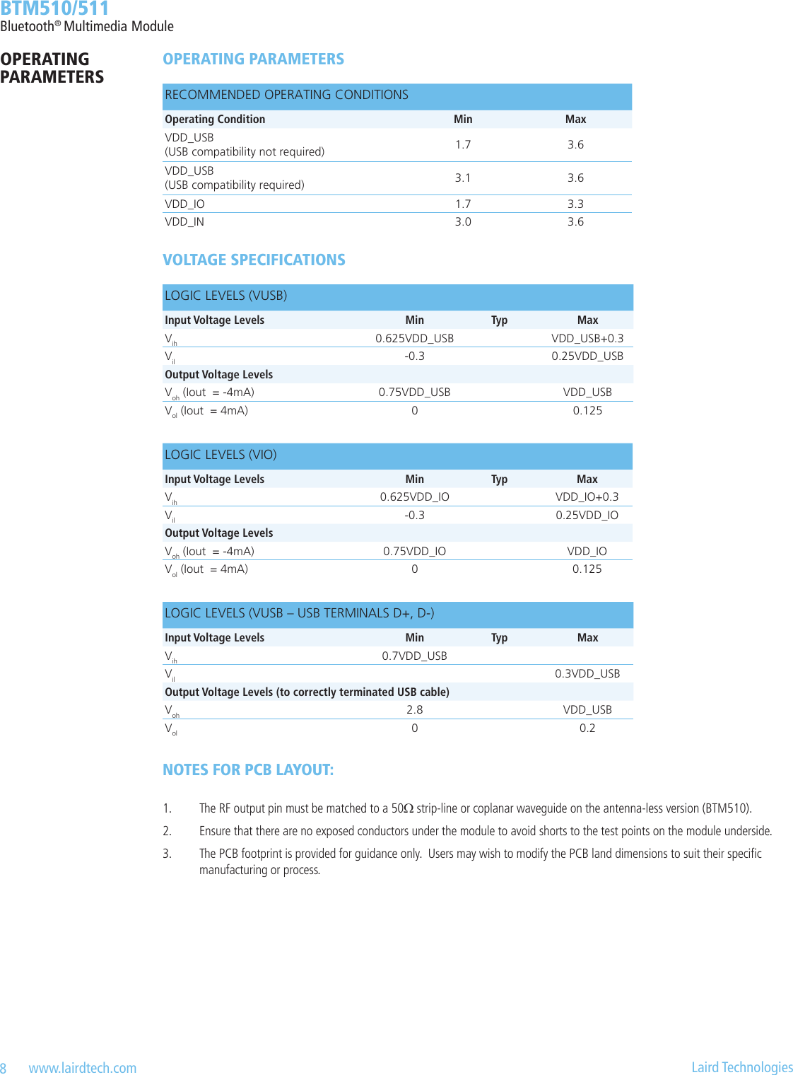
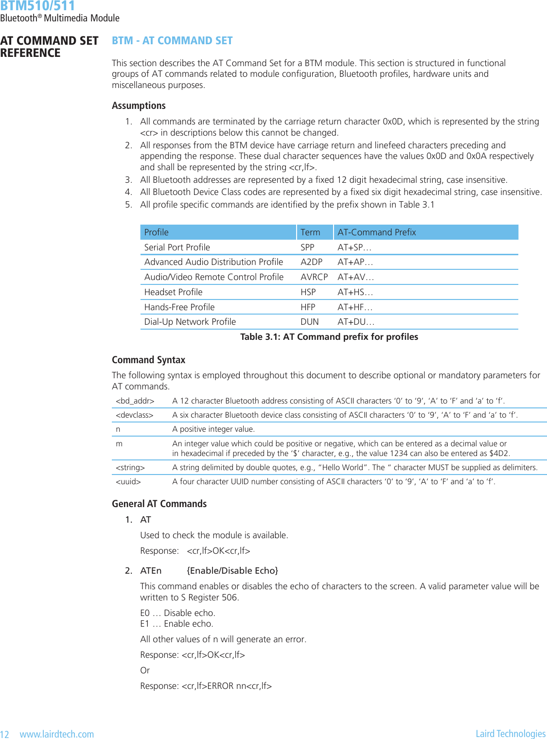
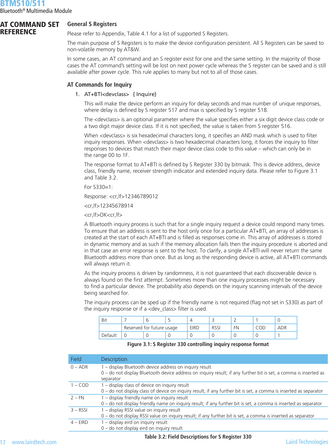
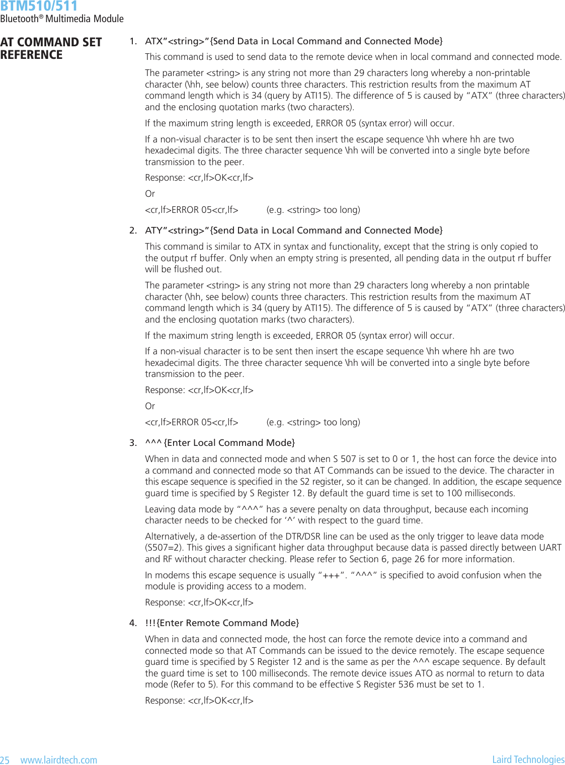
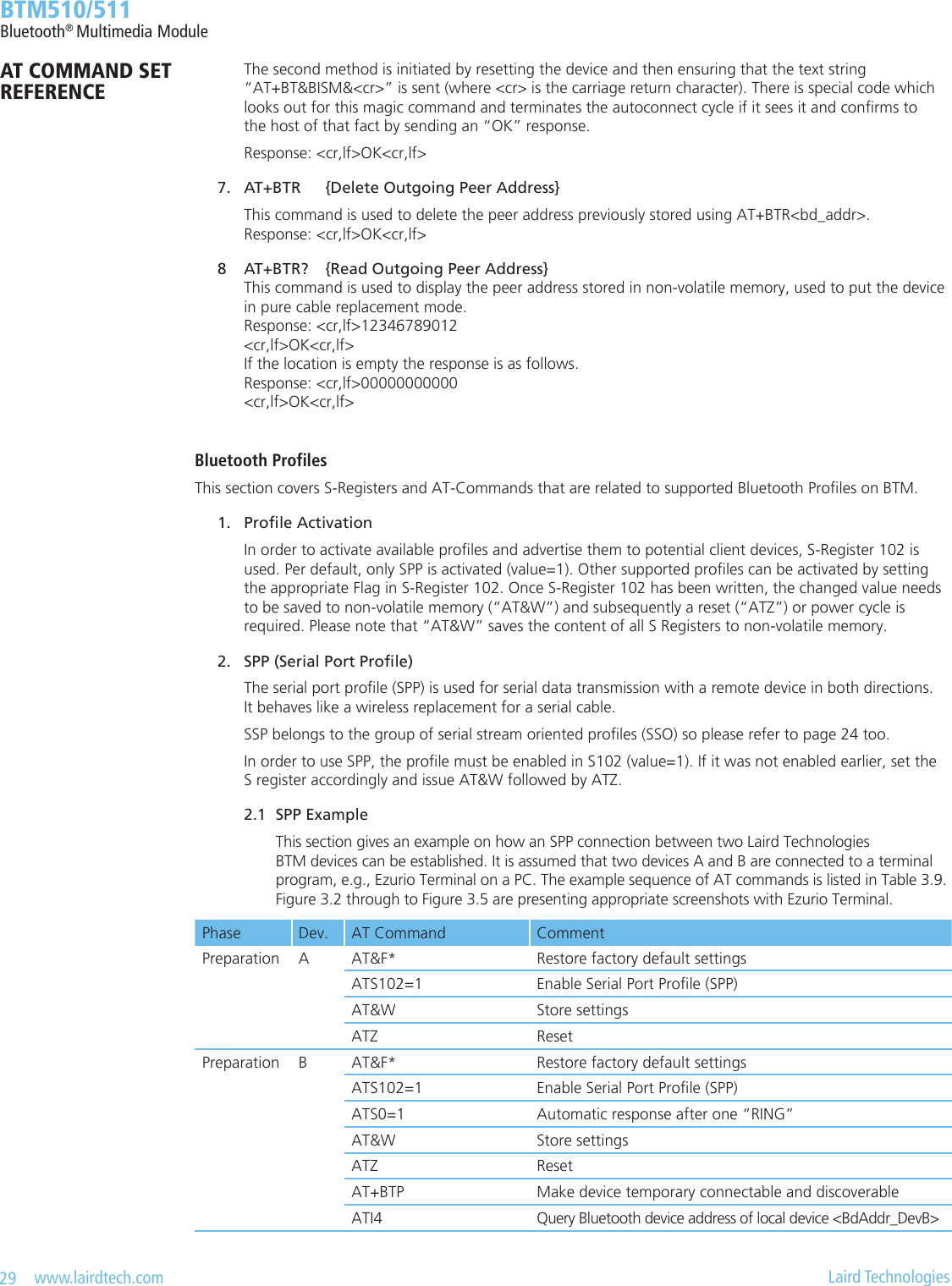
![13 www.lairdtech.com Laird Technologies BTM510/511Bluetooth® Multimedia Module 3. ATZ<n> {Hardware Reset and Emerge Into Boot Mode ‘n’} Forces the device through a hardware reset which means it will eventually come alive in the local command and unconnected mode. This allows changes to the non-volatile memory to take effect. The module will issue an OK response after the reset is complete and it is ready to receive commands once again. ATZ and ATZ0 signify reset and emerge into the current boot mode (see command ATI14). ATZ1 to ATZ4 instructs the module to reset and then emerge into the appropriate boot mode. Note that S Register 103 species the boot mode from cold. Boot modes are required to congure some low level device settings which cannot be congured by S registers and AT commands. Currently there are predened settings dening the PCM data format to be used with certain codec ICs (applies mainly to BC04). Response after reset: <cr,lf>OK<cr,lf> 4. AT+BTC<devclasshex> {Set Device Class Code Temporarily} This command is used to set the device class code which will be sent in subsequent inquiry responses. It can be read back using the AT+BTC? Command, as described below. <devclass> is a six digit hexadecimal number derived as per “Bluetooth Assigned Numbers” [8]. The 24 bits are made of four elds briey described as follows (bit 0 corresponds to the least signicant bit):-Bits 0-1: Format Type. This eld currently only has a value of 00 (i.e., format type 1).Bits 2-7: Minor Device Class: The value of these six bits is interpreted differently based on the Major Device Class stored in the next ve bits.Bits 8-12: Major Device Class: Five bits, refer to Figure 1 and Table 3 in “Bluetooth Assigned Numbers” [8].Bits 13-23: Major Service Class: 11 bit eld, used as a mask to dene service classes, refer to Figure 1 and Table 2 in “Bluetooth Assigned Numbers” [8]. Laird Technologies devices do not map to any predened Major Service Class or Major Device Class and so the default devclass as shipped is 001F00, which means no Major Service Class and “Unclassied” Major Device class. Other examples of device class codes are follows:Code (Hexadecimal) Name Major Service Major Device Minor Device0x001F00 Unclassied None Unclassied n/a0x200404 Headset Audio Audio Headset There is a tool available in the Internet for creating a particular device class code: refer to [9]. A device class set by AT+BTC becomes visible immediately but will be lost on next power cycle. Response: <cr,lf>OK<cr,lf> Or for an invalid <devclass> value (usually a value which is not 6 hexadecimal characters long): Response: <cr,lf>ERROR 08<cr,lf> 5. ATS515=<devclasshex> {Set Device Class Code Permanently} S Register 515 is used to set the device class code permanently. Use AT&W to save the setting to non-volatile memory. The new value will become visible on next power cycle which can be initiated by ATZ. Refer to number 4 for more information about the device class code. Response: <cr,lf>OK<cr,lf> 6. AT+BTC? {Read Device Class Code} This command is used to read the current device class code. Response: <cr,lf>123456 <cr,lf>OK<cr,lf>AT COMMAND SET REFERENCE](https://usermanual.wiki/Ezurio/511B/User-Guide-1215695-Page-13.png)
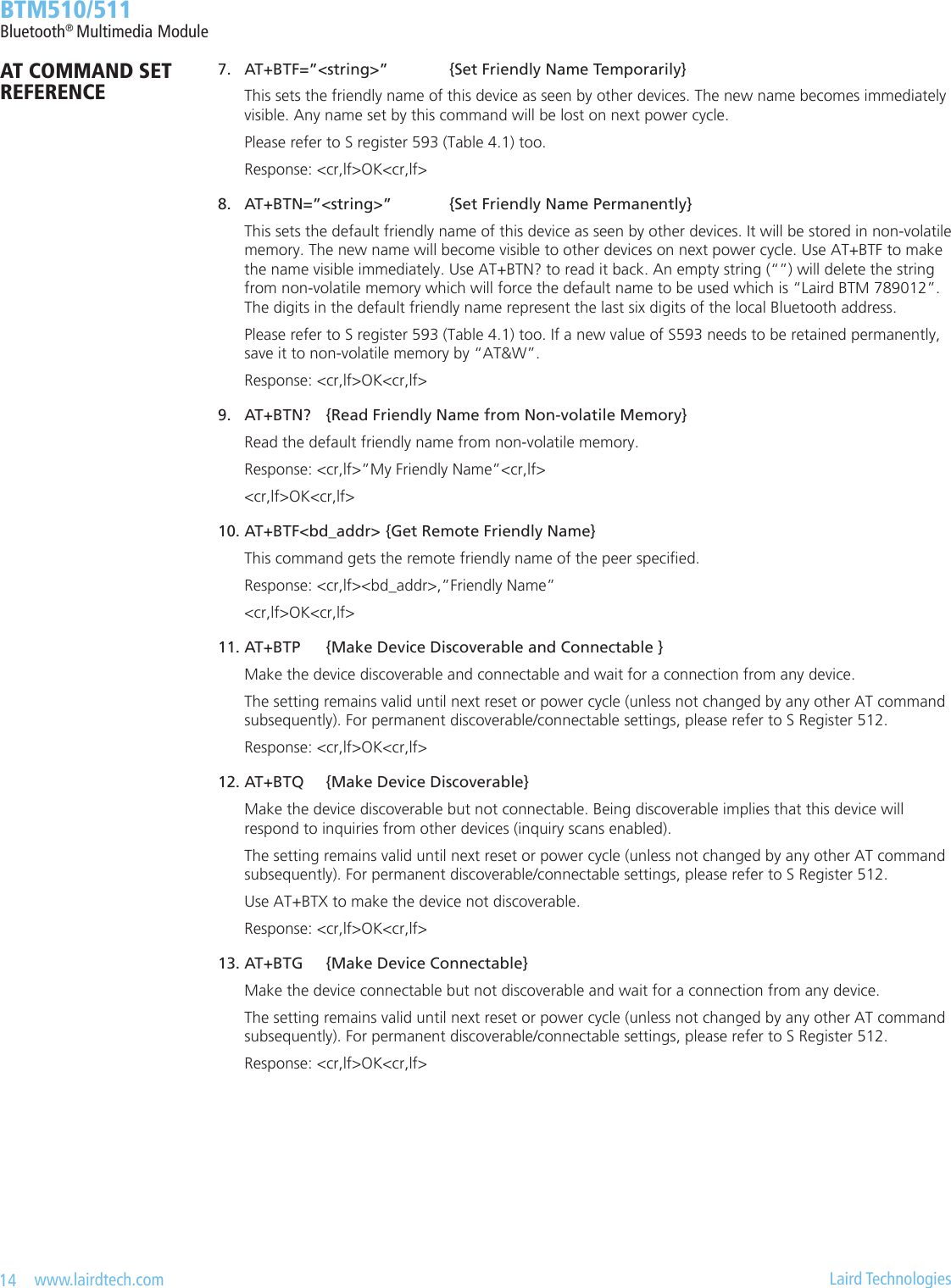
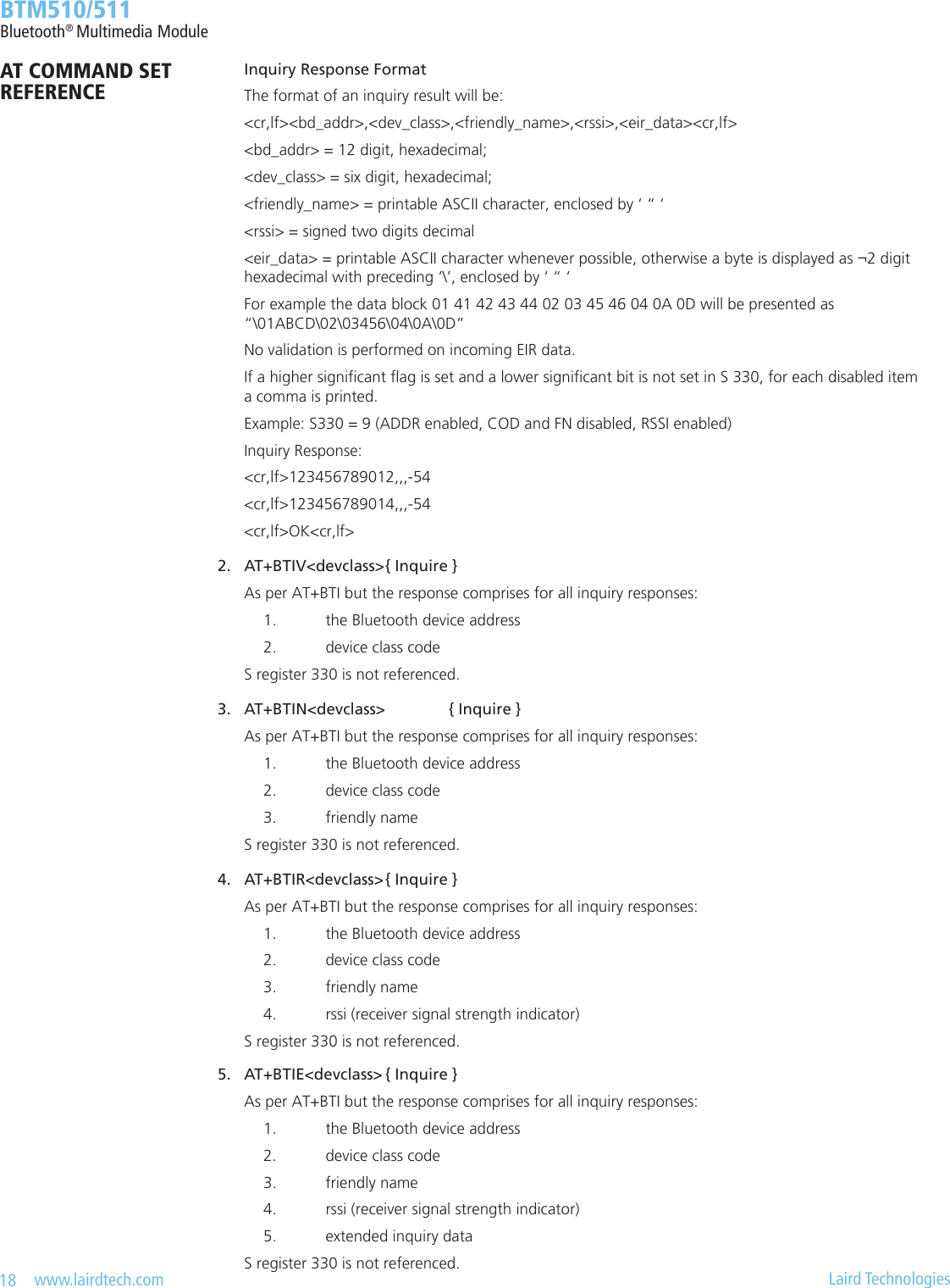
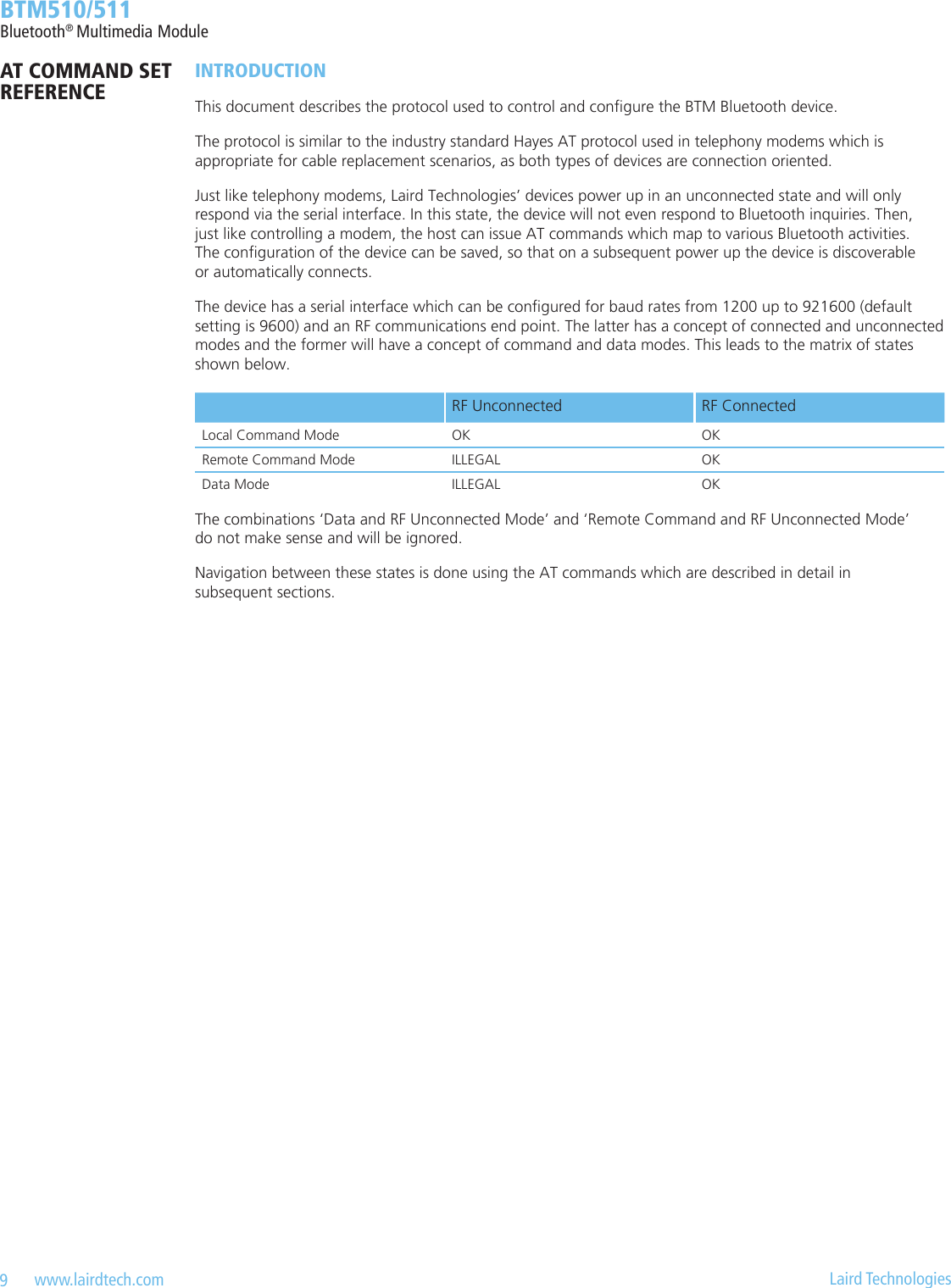
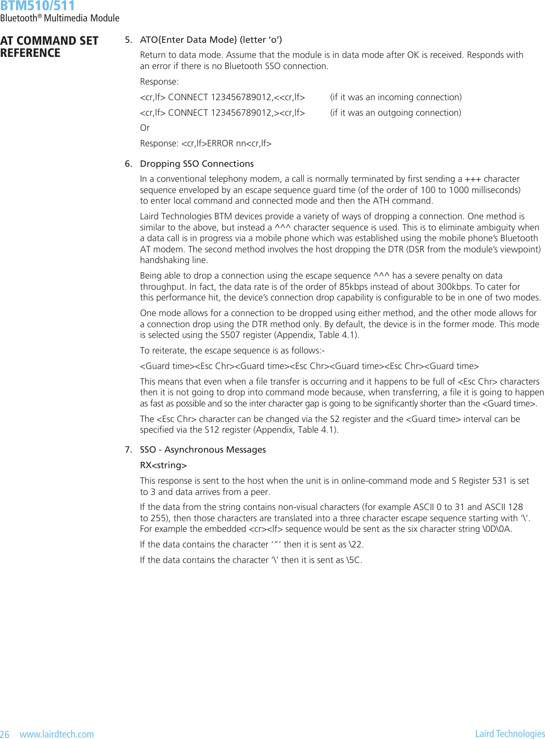
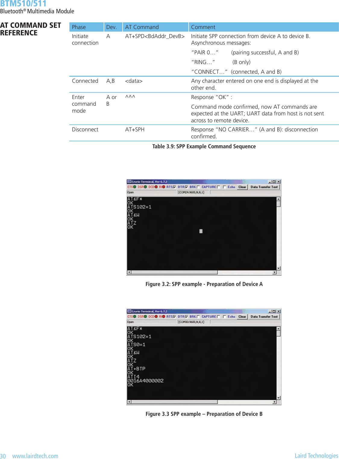
![19 www.lairdtech.com Laird Technologies BTM510/511Bluetooth® Multimedia Module6. AT+BTE=”<EIR-Data>” {Set Up Outgoing EIR Data} This command sets up outgoing EIR (extended inquiry response) data. Format: <EIR-Data> = printable ASCII character whenever possible, otherwise a two digit hexadecimal with preceding ‘\’ presenting one byte. Please note that the given data is written to baseband as it is (raw data) and no checks on the data format is performed. Hence, the user is responsible for writing data that corresponds to the extended inquiry response data format as described in the Bluetooth Specication Version 2.1 + EDR [1], vol3, Part C – Generic Access Prole, 8 Extended Inquiry Response Data Format (page 1305 in the .pdf-le). Response: <cr,lf>OK<cr,lf> 7. AT+BTE? {Query Outgoing EIR Data} This command prints the outgoing EIR data that is currently set up Response: <cr,lf> <EIR-Data> <cr,lf>OK<cr,lf>Secure Simple Pairing (SSP)Secure Simple Pairing (SSP) has been introduced since Bluetooth 2.1 + EDR. It aims to increase the security provided by a Bluetooth link whilst making the pairing process more user friendly.There are white papers about SSP available through the Internet (provided by the Bluetooth SIG and other com-panies), explaining the mechanisms and backgrounds of SSP. They can be found by searching the Internet for, e.g., “Bluetooth Secure Simple Pairing”. Please familiarize with those documents to get a better understanding of SSP and the following settings. 1. Security Level (S320) The security level is dened in the BT2.1+EDR specication [1], vol3, Generic Access Prole (Table 5.7). There are 4 Levels providing different levels of security:Security Level Characteristics CommentLevel 3 • MITM protection (MITM = “Man in the Middle” attack) • Encryption • User interactionHigh securityLevel 2 • No MITM protection • EncryptionMedium SecurityLevel 1 • No MITM protection • (No) Encryption (1) • Minimal user interactionLow SecurityLevel 0 • No MITM protection • No Encryption • Minimal user interactionPermitted only for service discovery(1) Although encryption is not necessary for security level 1, encryption will always be enabled because this specication mandates encryption for all services other than SDP (service discovery).Table 3.3: Security Levels The security level is dened by S Register 320 and is referenced at boot time only. Hence the register must be saved by “AT&W “ and the module must be power cycled (or “ATZ”) subsequently. S320 = 3 will overwrite the setting of S Register 322 (enable MITM). The security level will remain the same until next power cycle and is valid for all proles and services of the module. For SDP (service discovery prole), security level 0 is always assigned internally.AT COMMAND SET REFERENCE](https://usermanual.wiki/Ezurio/511B/User-Guide-1215695-Page-19.png)
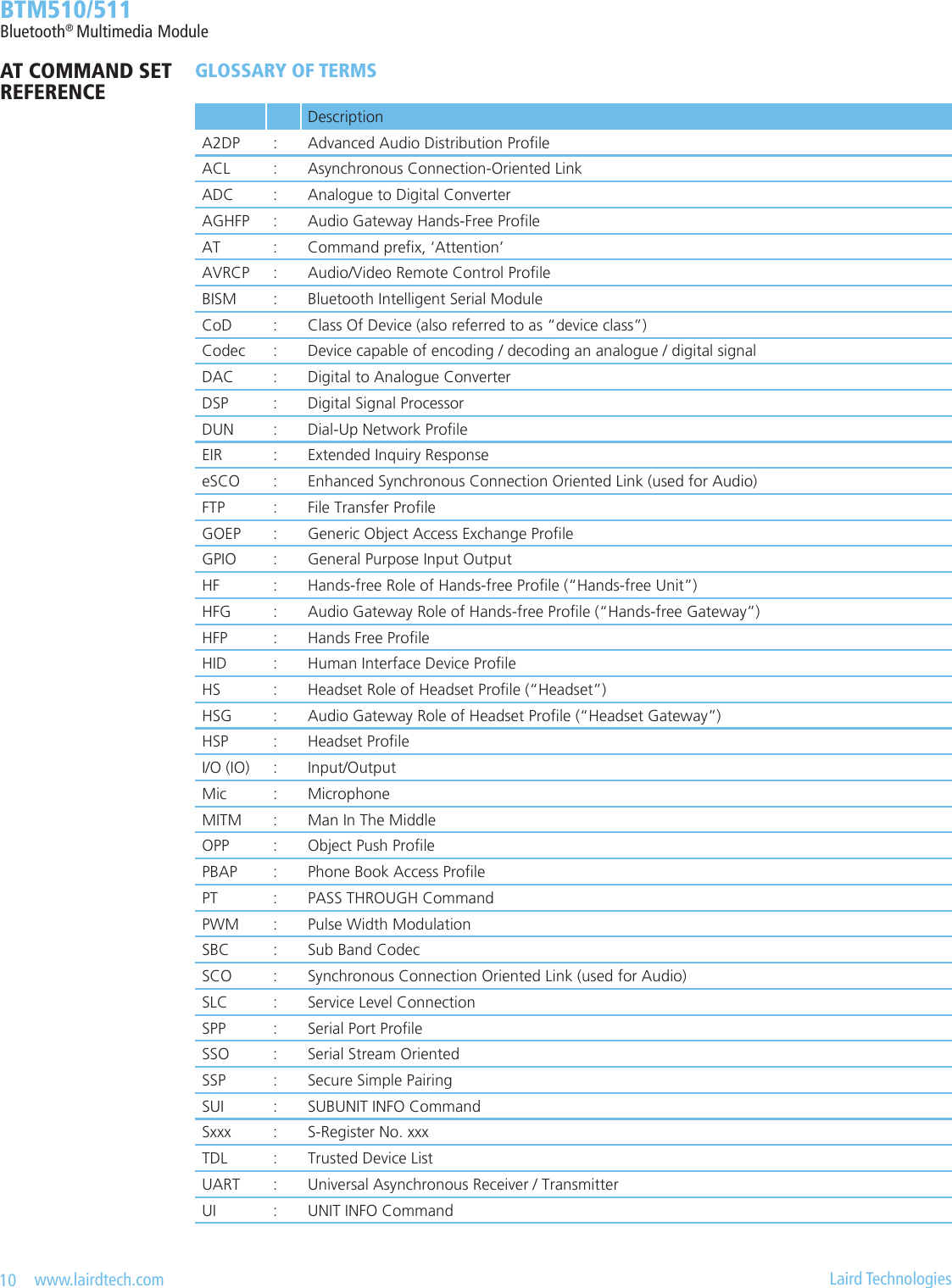
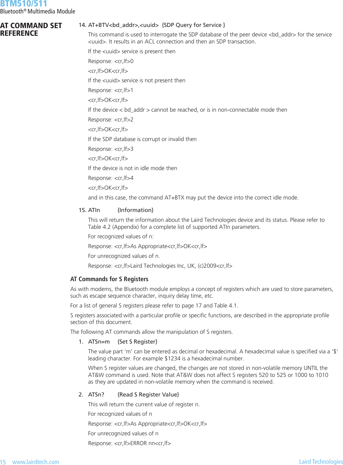
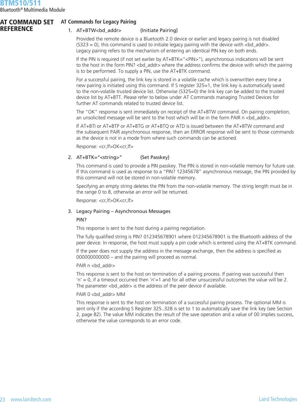
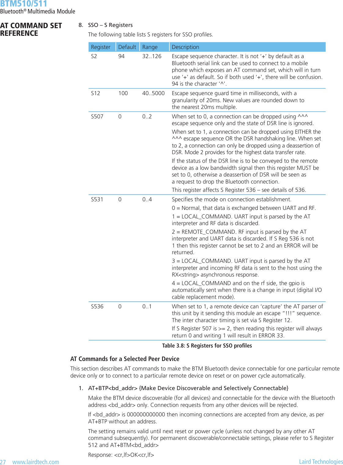
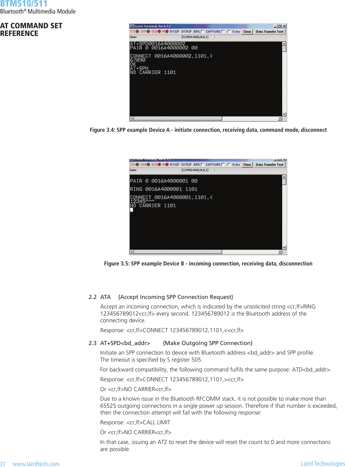
![20 www.lairdtech.com Laird Technologies BTM510/511Bluetooth® Multimedia Module 2. IO-Capability (S321) S-Register 321 denes the IO-capability of the device. The setting is used for IO-capability negotiations prior to SSP in order to identify whether the IO-capabilities of both devices are sufcient for MITM protection (if required). Table 3.4 lists possible values.S321 IO-Capability Comment0 Display only The device has the capability to display or communicate a six digit decimal number.1 Display yes no The device has the capability to display or communicate a six digit decimal number and at least two buttons that can be easily mapped to ‘yes’ and ’no’ or a mechanism whereby the user can indicate either ‘yes’ or ‘no’ (e.g., pressing a button within a certain time limit).2 Keyboard only The device has a numeric keyboard that can input numbers ‘0’ through ‘9’ and a conrmation. The device has also at least two buttons that can be easily mapped to ‘yes’ and ’no’ or a mechanism whereby the user can indicate either ‘yes’ or ‘no’ (e.g., pressing a button within a certain time limit).3 No input no output The device does not have the ability to indicate ‘yes’ or ‘no’, and the device does not have the ability to display or communicate a 6 digit decimal number.4 Reject IO-Cap requests IO-capability requests prior to SSP are rejected.Table 3.4: IO capabilities 3. Force Man-In-The-Middle Protection (MITM, S322) Protection against MITM-attacks can be enabled by S332. This S-Register only applies if the security level (S320) is less than 3. In case of security level (S320) = 3, MITM protection is always enabled and this S 322 is ignored. A new value written to S322 applies immediately. No power cycle is required. A link key created with MITM protection is named “authenticated link key”. A link key created without MITM protection is named “unauthenticated link key”. 4. Disable Legacy Pairing (S323) If the remote device is a legacy device (BT2.0 or earlier), legacy pairing with usage of PIN codes will be initiated. Legacy Pairing can be disabled by S-Register 323 = 1. Then pairing with legacy devices will always fail. 5. SSP Timeout (S324) The SSP timeout [s] is dened by S-Register 324. The timeout must be at least 60s to meet the BT specication requirements [1]. This time is required to be sufcient for the user to compare or read and input a 6 digit number. A time of 90 seconds is recommended which is the default value. 6. SSP Input Commands Table 3.5 lists all AT commands related to SSP input operations.AT Command Operation CommentAT+BTBY Accept pairing request Representing ‘yes’ inputAT+BTBN Reject pairing request Representing ‘no’ inputAT+BTB012345 Enter six digit passkey displayed by remote device Representing keyboard inputTable 3.5: SSP Input commandsAT COMMAND SET REFERENCE](https://usermanual.wiki/Ezurio/511B/User-Guide-1215695-Page-20.png)
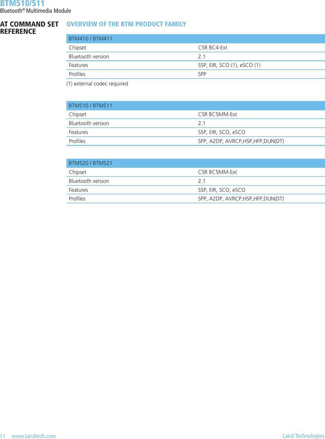
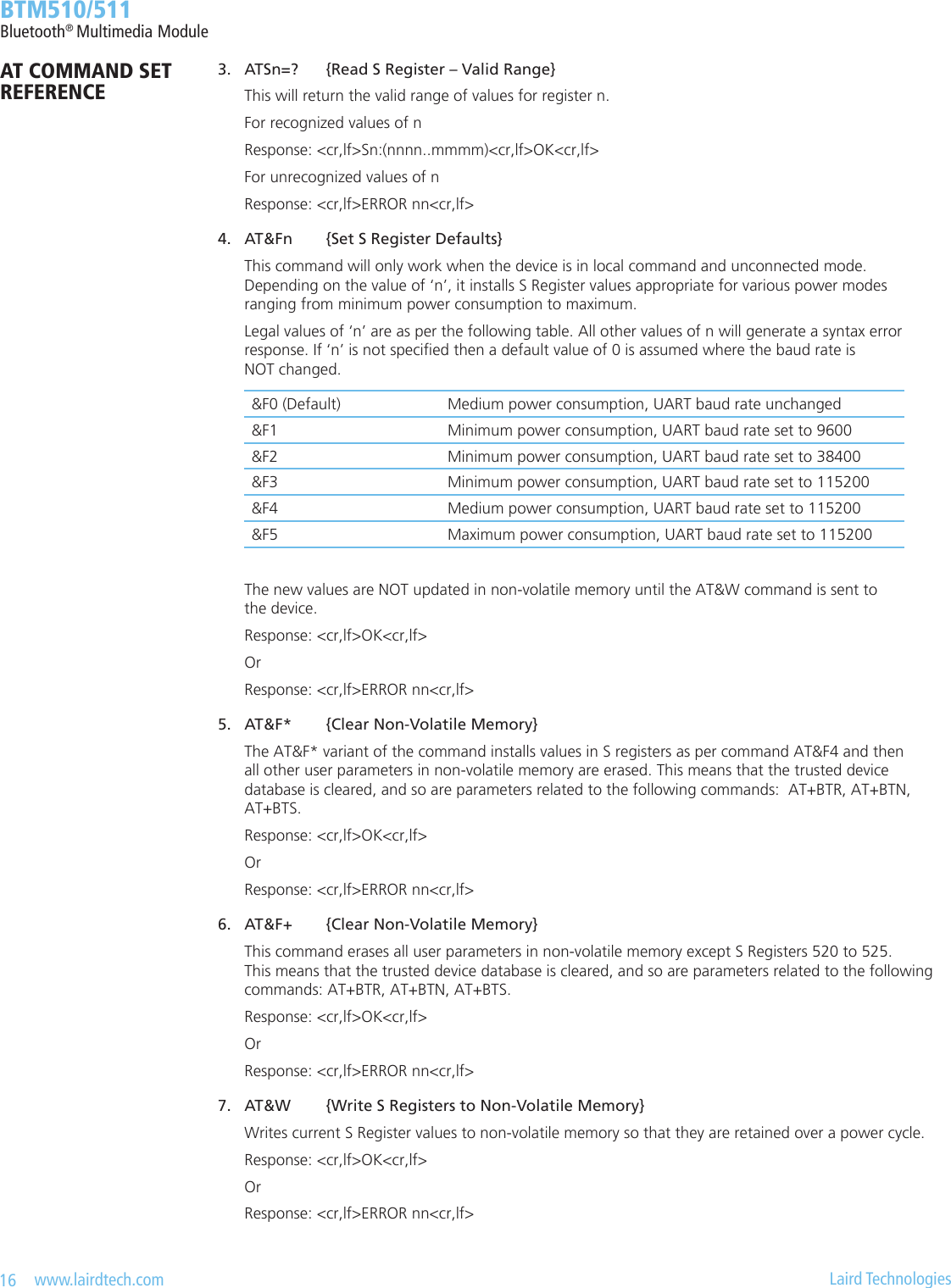
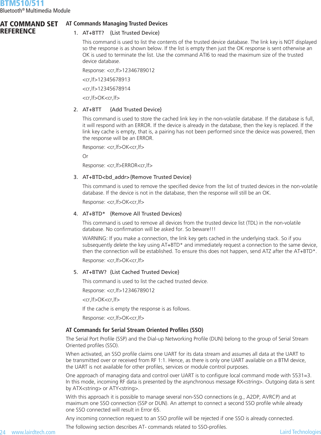
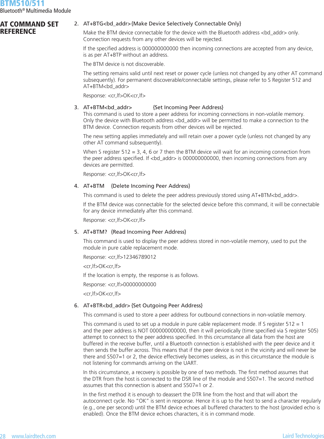
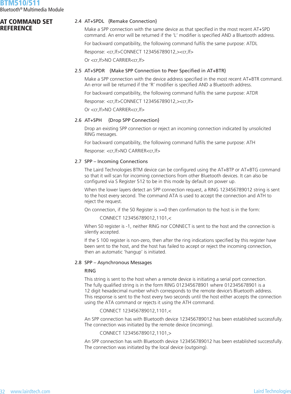
![21 www.lairdtech.com Laird Technologies BTM510/511Bluetooth® Multimedia Module 7. AT+BTW<bd_addr> {Initiate SSP} This command initiates secure simple pairing (dedicated bonding) with a device whose Bluetooth address is <bd_addr>. The correct term for this command’s action with respect to the Bluetooth specication 2.1+EDR [1] is “Dedicated Bonding”. Dedicated bonding means the exchange of link keys (pairing) without creating a connection to a particular prole or service immediately. The remote device must be a Bluetooth 2.1 device, otherwise (BT2.0 or earlier) legacy pairing will occur automatically if S323=0. For legacy pairing please refer to page 23. The “OK” response is sent immediately on receipt of the AT+BTW command. Depending on the combination of IO-capabilities of both devices, one of the asynchronous messages from Table 3.7 might appear during the pairing process. Please refer to that table for the required actions. On pairing completion, an unsolicited message in the form PAIR n <bd_addr> will be sent to the host. 8. S Registers for Secure Simple Pairing The following table lists all S Registers for Secure Simple Pairing. For the registers’ details please refer to their descriptions above. Register Default Range CommentS320 2 1..3 Security Level: see [1], vol3, Generic Access Prole - Table 5.7 needs subsequent ‘AT&W’ and power cycle to take effect value = 3 overwrites S322S321 1 0..4 Set IO capability: 0 – display only 1 – display yes no 2 – keyboard only 3 – no input no output 4 – reject IO-cap requestsS322 0 0..1 Force man-in-the-middle-protection (MITM): 0 – disabled 1 – enabled referenced only if security level (S320) < 3S323 0 0..1 Disable legacy (pre-BT2.1) Pairing: 0 – legacy pairing enabled 1 – legacy pairing disabledS324 90 1..255 Secure Simple Pairing timeout in s This value must be at least 60 in order to meet the recom-mendation of BT2.1 specicationTable 3.6: S-Registers for Secure Simple Pairing (SSP)AT COMMAND SET REFERENCE](https://usermanual.wiki/Ezurio/511B/User-Guide-1215695-Page-21.png)
![22 www.lairdtech.com Laird Technologies BTM510/511Bluetooth® Multimedia Module 9. Asynchronous SSP Messages Table 3.7 lists asynchronous messages which occur if MITM is enabled. The actually sent message depends on the combination of the IO capabilities of both ends. The combination of IO capabilities of both devices can also be insufcient for MITM protection. In that case the pairing will fail (PAIR 2 <BdAddr>). Please refer Table 5.6 in BT2.1+EDR specication [1], vol3, Generic Access Prole for sufcient combinations of IO-capabilities for MITM (=authenticated link key).Message Action / CommentPAIR ? <BdAddr>,”<friendlyname>”,<Passkey>Example:PAIR ? 0016A4000002,”Laird BTM000002”,863611Passkey compare request:Expecting the user to compare the passkey displayed on both ends and to conrm a match by “AT+BTBY” at both ends or reject by “AT+BTBN” if passkey does not match.PASSKEY ? <BdAddr>,”<friendlyname>”Example:PASSKEY ? 0016A4000001,”Laird BTM 000001”Passkey request:Expecting the user to enter the passkey displayed by the remote device. Use AT+BTB<passkey>, example: AT+BTB012345 *see(1) belowPAIR N <BdAddr>,”<friendlyname>”,<Passkey>Example:PASSKEY N 0016A4000002,”Laird BTM000002”,164585Passkey notication: Display BdAddr, friendly name and passkey to user.Expecting the user to enter the passkey from this message at the remote device’s numeric keyboard.PAIR 0 <BdAddr> <nn> Successfully paired with device of <BdAddr>. <nn> (optional) indicates the status of auto-matic storage to trusted device list. Value 0 = success; settings controlled by S325 to S328. Please refer to section 2.3, page 82.PAIR 1 <BdAddr> Pairing timeoutPAIR 2 <BdAddr> Pairing failedPAIR 3 <BdAddr> Pairing failed (too many repeat attempts)PAIR 4 <BdAddr> Pairing rejected by remote devicePAIR 5 <BdAddr> Pairing failed (unit keys not supported)PAIR 6 <BdAddr> Pairing failed (SSP not supported)PAIR 7 <BdAddr> Pairing failed (already busy with pairing)(1) If both devices have a “KeyboardOnly” capability, no pass key can be displayed. In that case, the user is required to invent and enter the identical 6 digit numeric passkey at both ends.Table 3.7: Asynchronous messages for SSP10. Known SSP Issues a.) General Bonding (automatic pairing on link setup if devices have not been paired previously) does not work with legacy devices (BT2.0 and earlier). If the remote device is BT2.0 or earlier, initiate dedicated bonding (AT+BTW<BdAddr>) prior to connection establishment. b.) Outgoing General Bonding (automatic pairing on link setup if devices have not been paired previously) with MITM does not work with two BTM devices, because any UART input on the initiating device is not accepted until the link has been established. Workaround: initiate dedicated bonding (AT+BTW<BdAddr>) prior to connection establishment. c.) If the link key of previously paired devices is not available any more in the remote device but still available in the trusted device list (TDL) of the local device (query by AT+BTT?), pairing will fail. In that case remove the device address from the local TDL using AT+BTD<BdAddr> and reinitiate pairing from the local device (AT+BTW<Bd_addr>).AT COMMAND SET REFERENCE](https://usermanual.wiki/Ezurio/511B/User-Guide-1215695-Page-22.png)
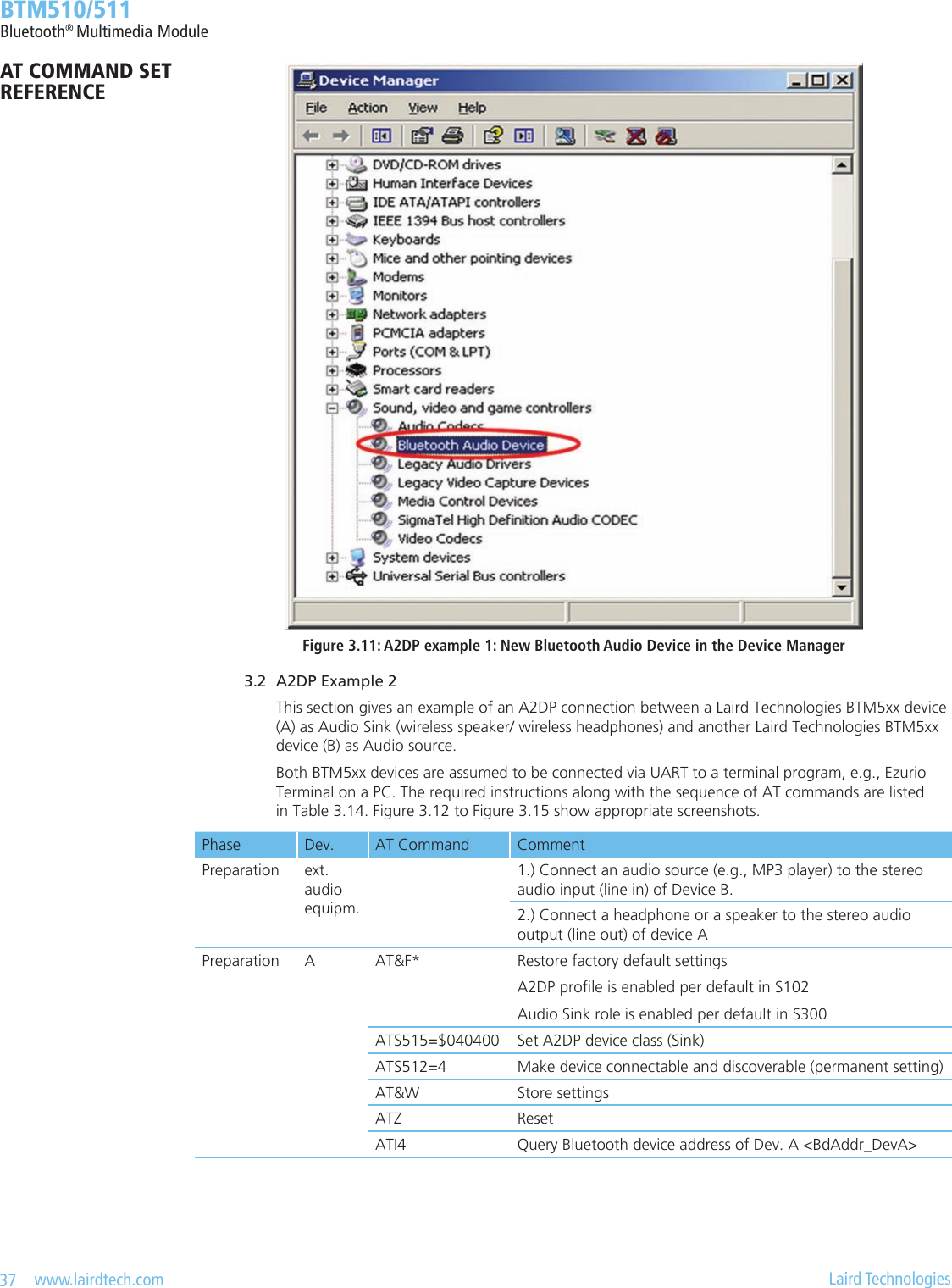
![40 www.lairdtech.com Laird Technologies BTM510/511Bluetooth® Multimedia Module 4. Set A2DP Device Class ATS515=$<device_classhex>; AT&W; ATZ For compliance with the A2DP specication, [2] (and hence for successful interoperability to other devices) it is required to set up a valid device class code. The default device class code of a BTM device is 0x001F00 which is invalid for the A2DP prole. The A2DP specication [2] mandates the following requirements for the device class of an A2DP device: 1. Mandatory to set the ‘Rendering’ bit for the SNK and the ‘Capturing’ bit for the SRC in the Service Class eld. 2. Recommended to set ‘Audio/Video’ as Major Device class both for the SNK and the SRC. 3. Select the appropriate Minor Device class as dened in the Bluetooth Assigned Numbers [8]. There is a tool available on the internet for creating a particular device class code: refer to [9]. With the assumptions above (Major Device class = Audio/Video), Table 8 in [8] gives the complete list of codes for the minor device class. If you are not sure about the minor device class, use the row marked with n/a for the minor device (e.g., 0x040400 for sink or 0x080400 for source). Table 3.15 gives some examples of device class codes for A2DP devices.Device Class Code Major Service Major Device Minor Device A2DP Role0x040400 Rendering Audio/Video n/a Sink0x040414 Rendering Audio/Video Loudspeaker Sink0x040418 Rendering Audio/Video Headphones Sink0x04041C Rendering Audio/Video Portable Audio Sink0x040420 Rendering Audio/Video Car audio Sink0x080400 Capturing Audio/Video n/a Source0x080410 Capturing Audio/Video Microphone Source0x080428 Capturing Audio/Video HiFi Audio Device SourceTable 3.15: A2DP device class code – examples The device class is written to the module using ATS515=$<device_classhex> where <device_classhex> is the 6 character device class code without leading “0x”. Use subsequent AT&W and ATZ for the new value to become effective. Please also refer to page 13, number 4. 4.1 Initiate A2DP Connection AT+APD<bd_addrhex> Initiate A2DP connection to Bluetooth address <bd_addrhex>. The remote device must support the complementary role to the local device. If link keys are missing in one or both devices, pairing will either occur automatically or pairing is required to be initiated by AT+BTW<bd_addrhex>. This depends on various factors like the combination of local and remote IO capabilities or the Bluetooth version of the remote device. Response: <cr><lf>OK<cr><lf> (immediately) <cr><lf>PAIR 0 <bd_addr> 00<cr><lf> (rst time only, auto pairing without MITM authent.) <cr><lf>CONNECT <bd_addr>,110D,><cr><lf> Or: <cr><lf>OK<cr><lf> (immediately) <cr><lf>NO CARRIER 110D<cr><lf> (not successful)AT COMMAND SET REFERENCE](https://usermanual.wiki/Ezurio/511B/User-Guide-1215695-Page-40.png)
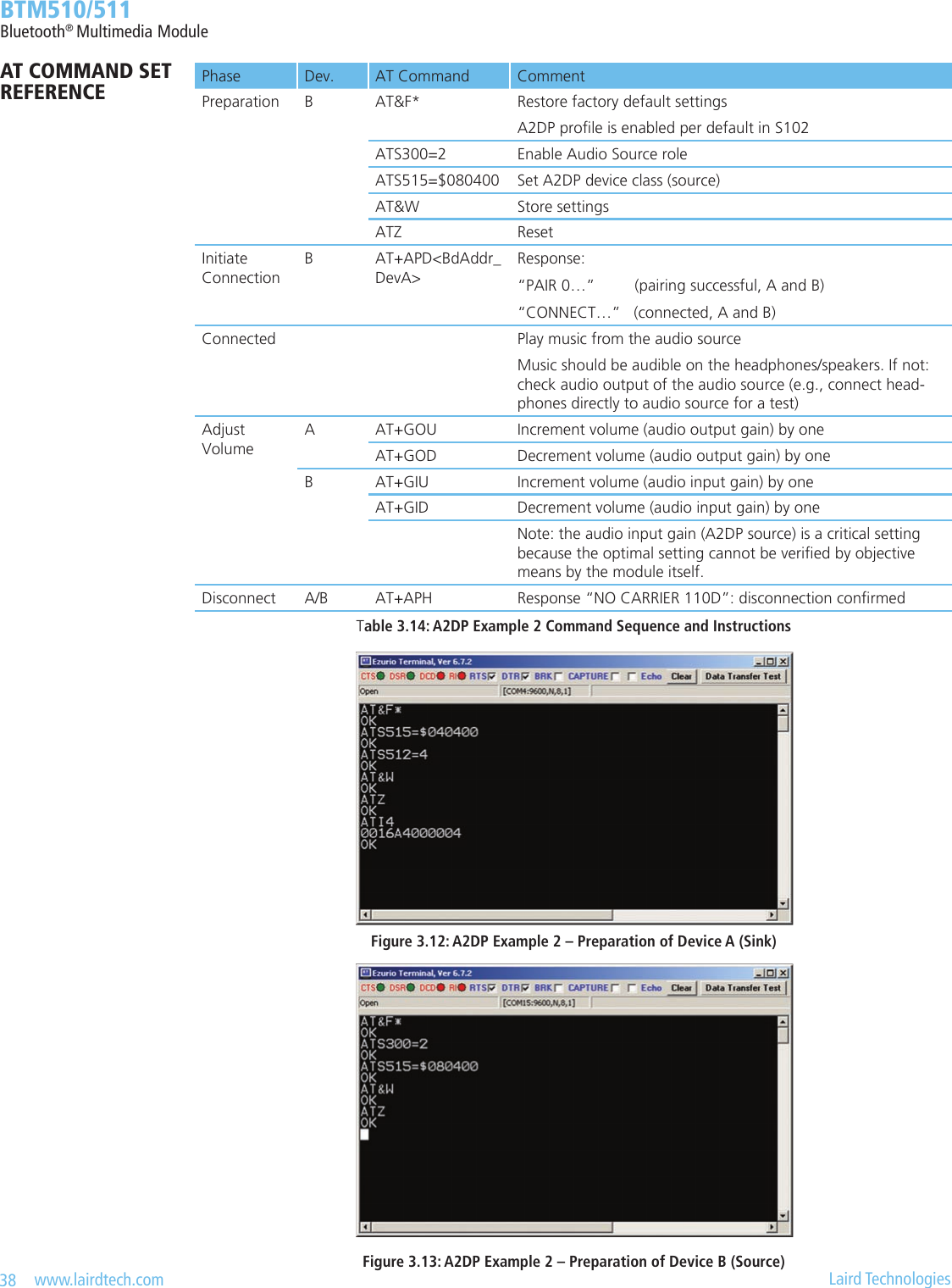
![41 www.lairdtech.com Laird Technologies BTM510/511Bluetooth® Multimedia Module 4.2 Output Gain Settings – A2DP Sink AT+GOU / AT+GOD AT+GOU – Increment audio output gain (volume). AT+GOD – Decrement audio output gain (volume). Response: <cr><lf>OK<cr><lf> <cr><lf>ERROR 57<cr><lf> – Maximum gain level reached <cr><lf>ERROR 58<cr><lf> – Minimum gain level reached The output gain level can be set directly using S register 589. Alternatively, S register 689 can be used to set the required overall output gain in dBr multiplied by 10. Please refer to section 1, page 74. 4.3 Input Gain Settings – A2DP Source AT+GIU / AT+GID AT+GIU – Increment audio input gain. AT+GID – Decrement audio input gain. Response: <cr><lf>OK<cr><lf> <cr><lf>ERROR 57<cr><lf> – Maximum gain level reached <cr><lf>ERROR 58<cr><lf> – Minimum gain level reached The input gain level can be set directly using S register 590. Alternatively, S register 690 can be used to set the required overall input gain in dBr multiplied by 10. Please refer to section 1, page 74. 4.4 Release A2DP Connection AT+APH / ATH110D Release an A2DP connection by AT+APH. Alternatively, ATH110D can be used. (110D presents the UUID for the A2DP prole). Please refer to section4, page 83. 4.5 Supported Features – A2DP Sink S312 Use S Register 312 to set the A2DP sink supported features that will be advertised in the A2DP service record. Refer to Table 3.16. The S register needs to be saved (AT&W) and the module needs to be power cycled (ATZ) for a new value to become effective. 4.6 Supported Features – A2DP Source S313 Use S Register 313 to set the A2DP source supported features that will be advertised in the A2DP service record. Refer to Table 3.16. The S register needs to be saved (AT&W) and the module needs to be power cycled (ATZ) for a new value to become effective.Task AT-Command / SRegister CommentEnable A2DP prole S102 128 = A2DP, Error 46 if A2DP role has not been set (see S300)Needs subsequent AT&W and ATZ to become effectiveSet A2DP role S300 [0..2] 0 = feature not set1 = A2DP Sink (default)2 = A2DP SourceNeeds subsequent AT&W and ATZ to become effectiveAT COMMAND SET REFERENCE](https://usermanual.wiki/Ezurio/511B/User-Guide-1215695-Page-41.png)
![42 www.lairdtech.com Laird Technologies BTM510/511Bluetooth® Multimedia ModuleTask AT-Command / SRegister CommentInitiate outgoing A2DP con-nectionAT+APD<bd_addr> Response if accepted:“CONNECT 0123456789012,110D,>”Response if rejected:“NO CARRIER 110D”Close only A2DP connection “AT+APH” or “ATH110D”Response:“NO CARRIER 110D” if connection has existed and S329=0“NO CARRIER” if connection has not existed and S329=0Close all connections ATH* Response:“NO CARRIER <proleUUID>” for each prole that was previously connected (see section 4, page 83)Set gain level S589 [0..22], default = 15Set codec output gain level (applies to sink)S590 [0..22], default = 15Set codec input gain level (applies to source)Set overall gain (dBr * 10) S689 [-450..215] Set codec output gain in dBr * 10 (applies to sink), default = 0S690 [-450..215] Set codec input gain in dBr * 10 (applies to source), default = 0Increment Gain AT+GOU Increment codec output gain by 1 step in gain table (refer to section 1, page 74)AT+GIU Increment codec input gain by 1 step in gain table (refer to section 1, page 74)Decrement Gain AT+GOD Decrement codec output gain by 1 step in gain table (refer to section 1, page 74)AT+GID Decrement codec input gain by 1 step in gain table (refer to section 1, page 74)Set A2DP Sink supported features bit maskS312 [1..15] Bitmask - sink supported features:Bit 0 = Headphone (default)Bit 1 = SpeakerBit 2 = RecorderBit 3 = AmplierSubsequent AT&W plus ATZ required for a new value to become effectiveSet A2DP Source supported features bit maskS313 [1..15] Bitmask - source supported features:Bit 0 = Player (default)Bit 1 = MicrophoneBit 2 = TunerBit 3 = MixerSubsequent AT&W plus ATZ required for a new value to become effectiveTable 3.16: A2DP – S Registers and AT-CommandsAT COMMAND SET REFERENCE](https://usermanual.wiki/Ezurio/511B/User-Guide-1215695-Page-42.png)
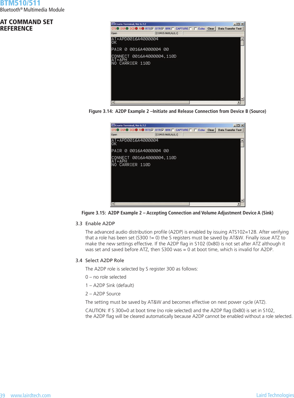
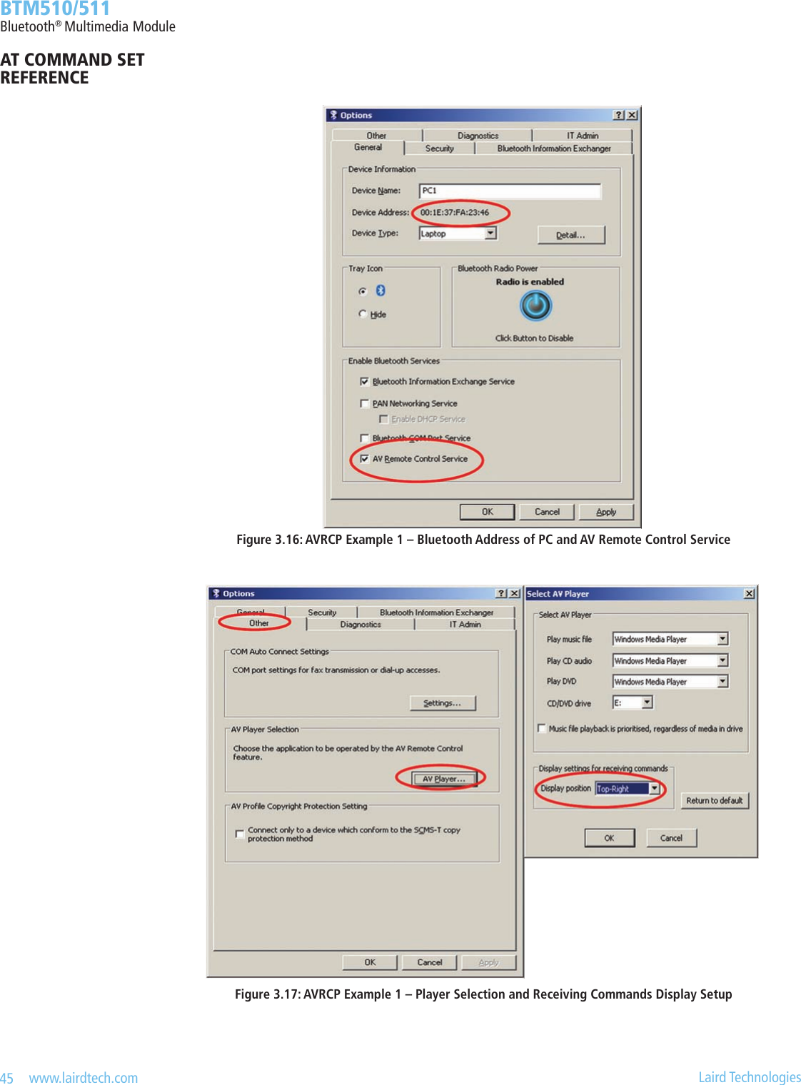
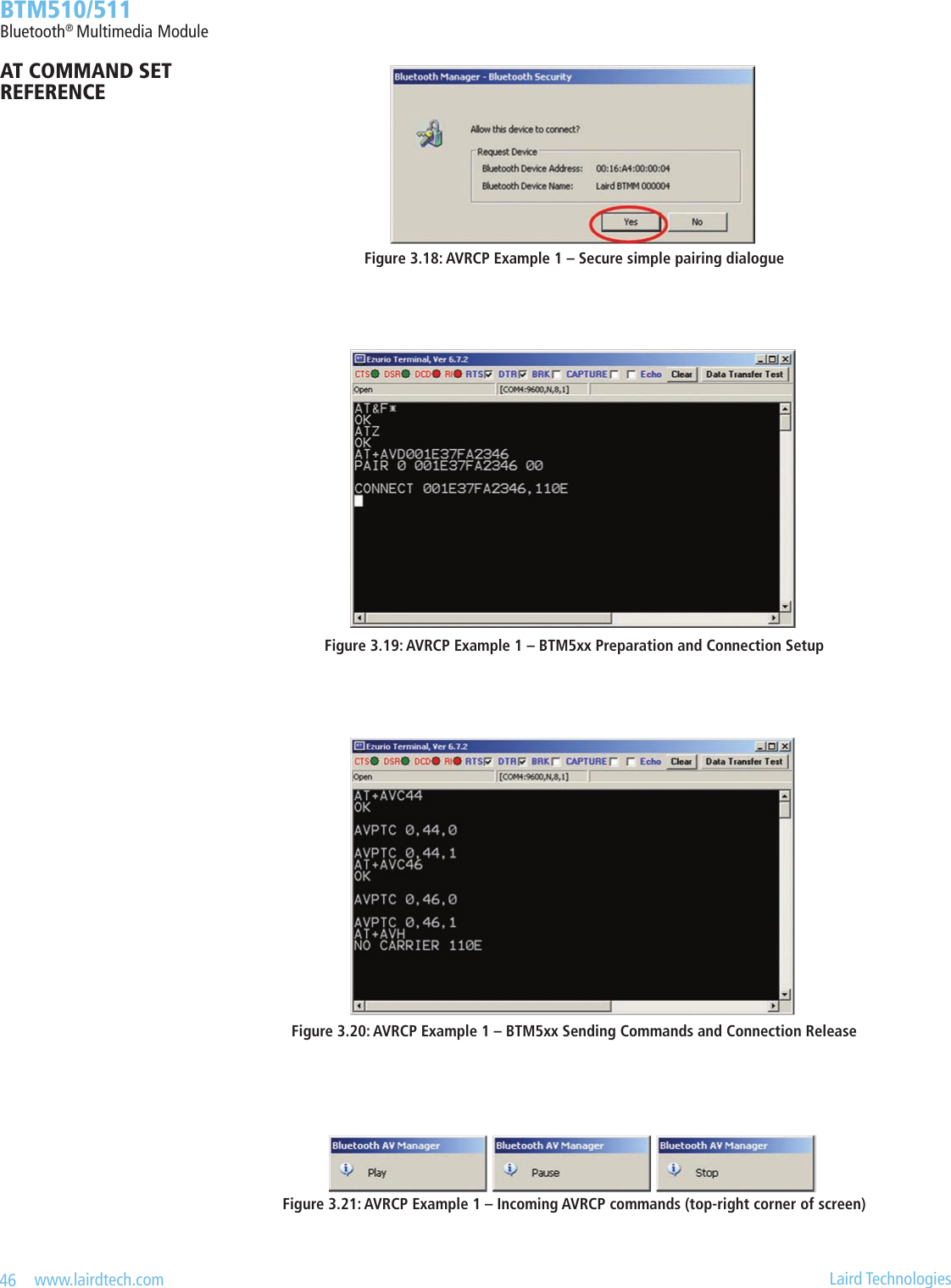
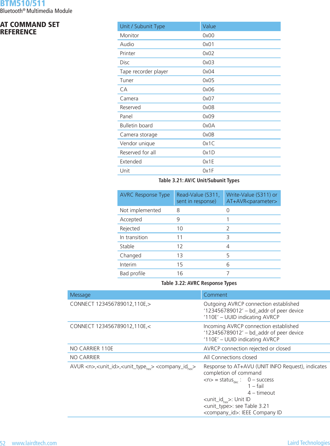
![43 www.lairdtech.com Laird Technologies BTM510/511Bluetooth® Multimedia Module 5 AVRCP(AudioVideoRemoteControlProle) The “Audio/Video Remote Control Prole” is used to remotely control audio or video streaming devices. A device must be dened as either control (CT) or target (TG). Furthermore, one of four categories (Player/Recorder, Monitor/Amplier, Tuner, Menu) must be assigned to a device. Version 1.0 of AVRCVP is supported. The AVRCP specication [3] adopts the AV/C Digital Interface Command Set (AV/C command set, dened by the 1394 Trade Association) device model and control message format. In this device model a remote control target consists of one or more subunits. At least the subunit ”PANEL” must exist. Remote control commands are passed to a subunit with the “PASS THROUGH” command. A BTM device, congured as target will support one PANEL-subunit. Table 3.17 gives an overview on supported AVRCP features on a BTM device.AVRCP Feature Support in CT (Control) Support in TG (Target)Spec. BTM5xx Spec. BTM5xx1. Connection establishment for control M Yes O Yes2. Release connection for control M Yes M Yes3. Sending UNIT INFO command O Yes X No4. Receiving UNIT INFO command X No M Yes5. Sending SUBUNIT INFO command O (1) X No6. Receiving SUBUNIT INFO command X No M Yes7. Sending VENDOR DEPENDENT command O No X No8. Receiving VENDOR DEPENDENT command X No O No9. Sending PASS THROUGH command M Yes X No10. Receiving PASS THROUGH command X No M YesM: mandatory O: optional X: excluded(1) incompleteTable 3.17: AVRCP Supported Features on BTM5xx 5.1 AVRCP Example 1 This section gives an example of an AVRCP connection between a Laird Technologies BTM5xx device as AVRCP Controller and a PC with a built in Bluetooth device and Toshiba Bluetooth Stack 2.1 as AVRCP Target. For any other Bluetooth Stack with AVRCP (target role) support, the setup should follow the steps of: 1. Identifying Bluetooth Device Address of PC 2. Enabling AV Remote Control Service 3. Selecting player and/or setup display of incoming remote control commands The BTM5xx device is assumed to be connected to a terminal program, e.g., Ezurio Terminal on a PC. The sequence of AT commands and the instructions for the PC side are listed in Table 3.18. Figure 3.16 to Figure 3.21 show appropriate screenshots. This example can be combined with the A2DP Example 1 (Section3.1, page 34). Then the AVRCP connection should be initiated after A2DP is connected.AT COMMAND SET REFERENCE](https://usermanual.wiki/Ezurio/511B/User-Guide-1215695-Page-43.png)
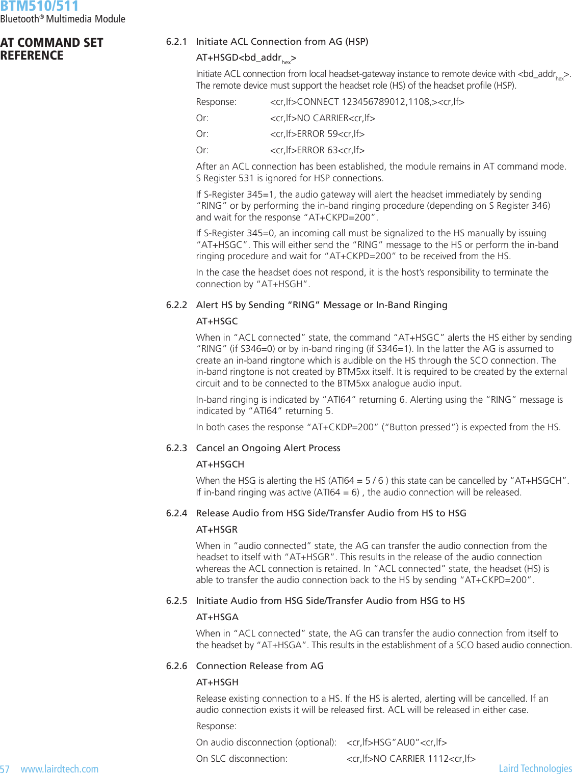
![47 www.lairdtech.com Laird Technologies BTM510/511Bluetooth® Multimedia Module 5.2 AVRCP - Control (CT) and Target (TG) This section describes AT Commands an S registers which are common to BTM5xx AVRCP Controller role and AVRCP Target role. 5.2.1 Initiate AVRCP Connection AT+AVD<bd_addrhex> Initiate AVRCP control connection to Bluetooth address <bd_addrhex>. The module must be congured as AVRCP Control by S register 301 = 1. Furthermore, a category must be selected in S register 302. Response: <cr,lf>CONNECT 123456789012,110E,><cr,lf> Or: <cr,lf>NO CARRIER 110E<cr,lf> Or: <cr,lf>ERROR 47<cr,lf> Or: <cr,lf>ERROR 48<cr,lf> After an AVRCP connection has been established, the module remains in AT command mode. S Register 531 is ignored for AVRCP connections. 5.2.2 Release AVRCP Control Connection AT+AVH Release AVRCP control connection. Response <cr,lf >NO CARRIER 110E<cr,lf> 5.3 AVRCP - Control (CT) This section describes AT Commands an S registers when BTM5xx is congured as an AVRCP Controller (S301=1). 5.3.1 Send UNIT INFO Request AT+AVU Send a Unit Info request to a connected AVRCP target. Response immediately: <cr,lf>OK<cr,lf> On command completion: <cr,lf>AVUR <n>,<unit_idhex>,<unit_typehex>,<company_idhex><cr,lf> <n> = statusdec: 0 – success 1 – fail 4 – timeout For unit_type see Table 3.21: AV/C Unit/Subunit Types. 5.3.2 Send SUBUNIT INFO Request (Incomplete*) AT+AVS<pagedec> Send a Subunit Info request to a connected AVRCP target. Response: <cr,lf>OK<cr,lf> (immediately) And: <cr,lf>AVSR <n>,<pagedec>,<pagedatahex> <cr,lf> (after command completion) <n> = statusdec: 0 – success 1 – fail 4 – timeout <pagedec> : requested page [0..31] <pagedata hex>: 1st word of requested page *) incomplete because only the rst word of the requested page is being displayed in the AVSR asynchronous messageAT COMMAND SET REFERENCE](https://usermanual.wiki/Ezurio/511B/User-Guide-1215695-Page-47.png)
![48 www.lairdtech.com Laird Technologies BTM510/511Bluetooth® Multimedia Module 5.3.3 Send Remote Control Command AT+AVC<operation_idhex>,<button_state> Send a remote control command to a connected AVRCP target. Internally, a PASS THROUGH command is created and sent to the PANEL subunit of the AVRCP target. <operation_idhex> is the value for the actual remote control command. Valid values are specied in Table 3.20. Some Operation IDs can be replaced by mnemonics, see Table 3.20. <button_state> represents “Button pushed” (=0) or “Button released” (=1) If <button_state> is not specied, two PASS THROUGH commands, each with button_state=0 and button_state=1, will be created and being sent consecutively. The “OK” response is sent immediately on receipt of AT+AVC command. On command completion, an unsolicited message will be sent to the host in the form “AVPTC <n>, <bd_addr>, <button_state>”. AVPTC means “AVrcp Pass Through Conrmation”. Parameter n indicates the command’s status: ‘n’=0: successful, command conrmation received from target ‘n’=1: timeout, target has not sent conrmation within the specied maximum time ‘n’=2: all other unsuccessful outcomes Parameters: <operation_idhex> (mandatory): see Table 3.20 <button_state> (optional) : ‘0’ - Button pushed ‘1’ - Button released Response: <cr,lf>OK<cr,lf> (immediately) And: <cr,lf>AVPTC <n>,<operation_idhex>,<button_state><cr,lf> (after command completion) If status n indicates an unsuccessful outcome,<operation_idhex> and <button_state> are omitted. 5.4 AVRCP – Target (TG) This section describes AT Commands an S registers when BTM5xx is congured as an AVRCP Target (S301=2). In this mode, BTM5xx supports one subunit PANEL (see [3]). 5.4.1 Incoming AVRCP Connection Request An incoming AVRCP connection request is accepted automatically if a valid link key for the paging device exists. If no link key is available, Secure Simple Pairing (SSP, BT2.1) or legacy pairing (BT2.0 or earlier) is carried out, depending on the Bluetooth Version of the paging device. After an AVRCP connection has been established, the module remains in AT command mode. S Register 531 is ignored for AVRCP connections. 5.4.2 UNIT INFO Response It is mandatory to respond to a UNIT INFO command if congured as AVRCP target. Required response parameters are IEEE Company ID and a Unit Type. The IEEE Company ID is a 24 bit integer which can be set via S Register 303. The response is sent automatically with the company ID as per S303 and a xed unit type of 0x09 (“Panel”). 5.4.3 SUBUNIT INFO Response It is mandatory to respond to a SUBUNIT INFO command if congured as AVRCP target. Required response parameters are Subunit type and MaxSubUnitId. The response is sent automatically with a xed value of 0x09 (“Panel”) for parameter Subunit type and a xed value of 0x00 for parameter MaxSubUnitId (only one subunit exists, which is panel).AT COMMAND SET REFERENCE](https://usermanual.wiki/Ezurio/511B/User-Guide-1215695-Page-48.png)
![49 www.lairdtech.com Laird Technologies BTM510/511Bluetooth® Multimedia Module 5.4.4 PASS THROUGH Indication An incoming PASS THROUGH command will be indicated by an unsolicited message. AVPTI <subunit_idhex>,<operation_idhex>,<button_state> For subunit_idhex see Table 3.21. For operation_idhex see Table 3.20. <button_state>: ‘0’ is Button pushed ‘1’ is Button released 5.4.5 PASS THROUGH Response AT+AVR<avrc_response_typehex> If S register 310 == 0, a Pass Through (PT) response is required from the host. The response is sent using the command: AT+AVR<avrc_response_typedec> Parameter: <avrc_response_typedec>: see Table 3.22, write-value. If S register 310 == 1, a Pass Through response is sent automatically with an <avrc_response_type> dened by S register 311. In this case, the host is not required to respond.Task AT-Command / S Register CommentEnable AVRCP prole S102 256 = AVRCP, Error 47 if AVRCP role has not been set (see S301);Error 48 if S301== 2 and Category has not been set (see S302)Needs subsequent AT&W and ATZ to be-come effectiveSet AVRCP role S301 [0..2] 0 = disabled 1 = Control “CT” (default) 2 = Target “TG” Needs subsequent AT&W and ATZ to be-come effectiveSet AVRCP category S302 [0..4] 0 = Feature disabled (default) 1 = Player/Recorder 2 = Monitor/Amplier 3 = Tuner 4 = Menu Needs subsequent AT&W and ATZ to be-come effectiveInitiate outgoing AVRCP con-trol connectionAT+AVD<bd_addr> Response if accepted: “CONNECT 0123456789012,110E,>”Response if rejected: “NO CARRIER 110E”Close only AVRCP connection “AT+AVH“ or “ATH110E” Response: “NO CARRIER 110E” if connection has existed and S329=0 “NO CARRIER” if connection has not existed and S329=0Close all connections ATH* Response: “NO CARRIER <proleUUID>” for each prole that was previously connected (see section 4, page 83)Send remote control command (Control)AT+AVC<operation_idhex>,<state><operation_idhex>: see Table 3.20 <state> (optional): ‘0’ Button pushed ‘1’ Button released Response on command completion: “AVPTC <n>,<operation_idhex>,<state>”AT COMMAND SET REFERENCE](https://usermanual.wiki/Ezurio/511B/User-Guide-1215695-Page-49.png)
![50 www.lairdtech.com Laird Technologies BTM510/511Bluetooth® Multimedia ModuleTask AT-Command / S Register CommentSend a Unit Info request (Control)AT+AVU Response on command completion: “AVUR <n>,<unit_idhex>,<unit_typehex>,<company_idhex>” Successful if <n> = 0Send a Subunit Info request (Control)AT+AVS (incomplete*) Response on command completion: “AVSR <n>,<pagedec>,<pagedatahex> <cr,lf>” Successful if <n> = 0 *) only rst word of the pagedata is being displayed in the AVSR response messageSet Company Id (Target) S303 [0..0xFFFFFF] IEEE Company ID, 24bit hexadecimal, Required for UNIT INFO Response in AVRCP target mode, default value is 0.Set Unit Type (Target) S304 [0..0xFF] currently always 0x09, read only, reserved for future usageEnable Unit Info Response (Target)S305 [0..1] 0 – reject incoming Unit Info Requests 1 – accept incoming Unit Info Requests and send response automatically (default) with Company ID as per S303 and unit type = 0x09 (“Panel”, xed)Enable Subunit Info Response (Target)S306 [0..1] 0 – reject incoming Subunit Info Requests 1 – accept incoming Subunit Info Requests and send response automatically (default) with Subunit type = 0x09 (“Panel”, xed) and MaxSubUnitId = 0x00 (xed)Congure PASS THROUGH (PT) Response (Target)S310 [0..1] 1 = Enable automatic PT-response, response type is read from S311, (default) 0 = Host is required to respond to PT-Indica-tion, see ‘AT+PTR’Set automatic PT response type (Target)S311 [0.. 7] This value is queried for automatic PT-Re-sponse, see Table 3.22 Default value is “accepted” 1w/ 9rRespond to incoming Pass Through command (Target)AT+AVR<avrc_response_typehex><avrc_response_typehex>: see Table 3.22 If S 310 == 1, response from host is not required.Table 3.19: AVRCP – S Registers and AT CommandsAT COMMAND SET REFERENCE](https://usermanual.wiki/Ezurio/511B/User-Guide-1215695-Page-50.png)

![53 www.lairdtech.com Laird Technologies BTM510/511Bluetooth® Multimedia ModuleMessage CommentAVSR <n>,<pagedec>,<pagedatahex>Response to AT+AVS (SUBUNIT INFO Request), Indi-cates completion of command <n> = statusdec: 0 – success 1 – fail 4 – timeout <pagedec> : requested page [0..31] <pagedatahex> : 1st word of requested pageAVPTI <subunit_idhex>,<operation_idhex>,<state> Indication of incoming Pass Through command <subunit_idhex>: subunit id <operation_idhex>: see Table 3.20 <state>: ‘0’ – Button pushed ‘1’ – Button releasedAVPTC <n>,<operation_idhex>,<state> Conrmation of AT+AVC (Control Command Request) <n>: ‘0’ – successful ‘1’ – timeout ‘2’ – not successful, other than timeoutTable 3.23: AVRCP Unsolicited Messages 5.5 AVRCP GPIO Mapping GPIOs can be mapped to AVRCP Commands (operations) with GPIO Conguration Registers S 651 to 663. If Function mapping is enabled (FME=1), and if a valid av_operation_id (see Table 3.20) is assigned to a GPIO and if the module is congured as AVRCP Control (S 301), a rising edge causes the appropriate command request to be sent to the connected AVRCP target as if AT+AVC was issued with <state>=0 (Button pushed). A trailing edge on this GPIO will cause the same command to be sent with <state>=1 (Button released). The logical level of a GPIO can be inverted by setting the appropriate ag “INV” in the appropriate GPIO conguration register. If congured as AVRCP Target, the direction ag (DIR) in the GPIO Conguration Register must be set to 1 in order to indicate received commands at a digital output. A write operation to a GPIO will not have any effect if that GPIO is mapped to AVRCP. The level inversion Flag INV of the GPIO Conguration Register also applies in target mode. Restrictions can apply if certain GPIOS will be reserved for other functions in future, e.g. coexistence supporting functionality. Please refer to section Error! Reference source not found. 6. HSP(HeadsetProle) The “Headset Prole” provides full-duplex audio capability combined with minimal device control commands. Audio bandwidth is limited and deemed to be sufcient for, e.g., voice links. Table 3.24 lists the feature requirements of the HSP specication [4] and the level of support by BTM5xx. Version 1.2 of the Headset Prole specication is supported. In most cases it will be preferred to use the more advanced Hands-Free Prole (HFP). HSP denes the role of the headset (HS) and the role of the audio gateway (AG) which are both supported on BTM5xx. They are enabled by setting the appropriate ag in S-Register 102 (plus subsequent “AT&W” and “atz“). An HSP connection can be in one of two states: ACL connected or audio connected. The ACL is initiated by either HS or AG. The audio connection (a SCO link) shall always be initiated and released by the AG. A host processor is required, using AT commands to control the BTM5xx module (hosted operation mode). An AT command beginning with AT+HS... indicates afliation to the Headset role of HSP. An AT command beginning with AT+HSG…indicates afliation to the Audio Gateway role of HSP.AT COMMAND SET REFERENCE](https://usermanual.wiki/Ezurio/511B/User-Guide-1215695-Page-53.png)
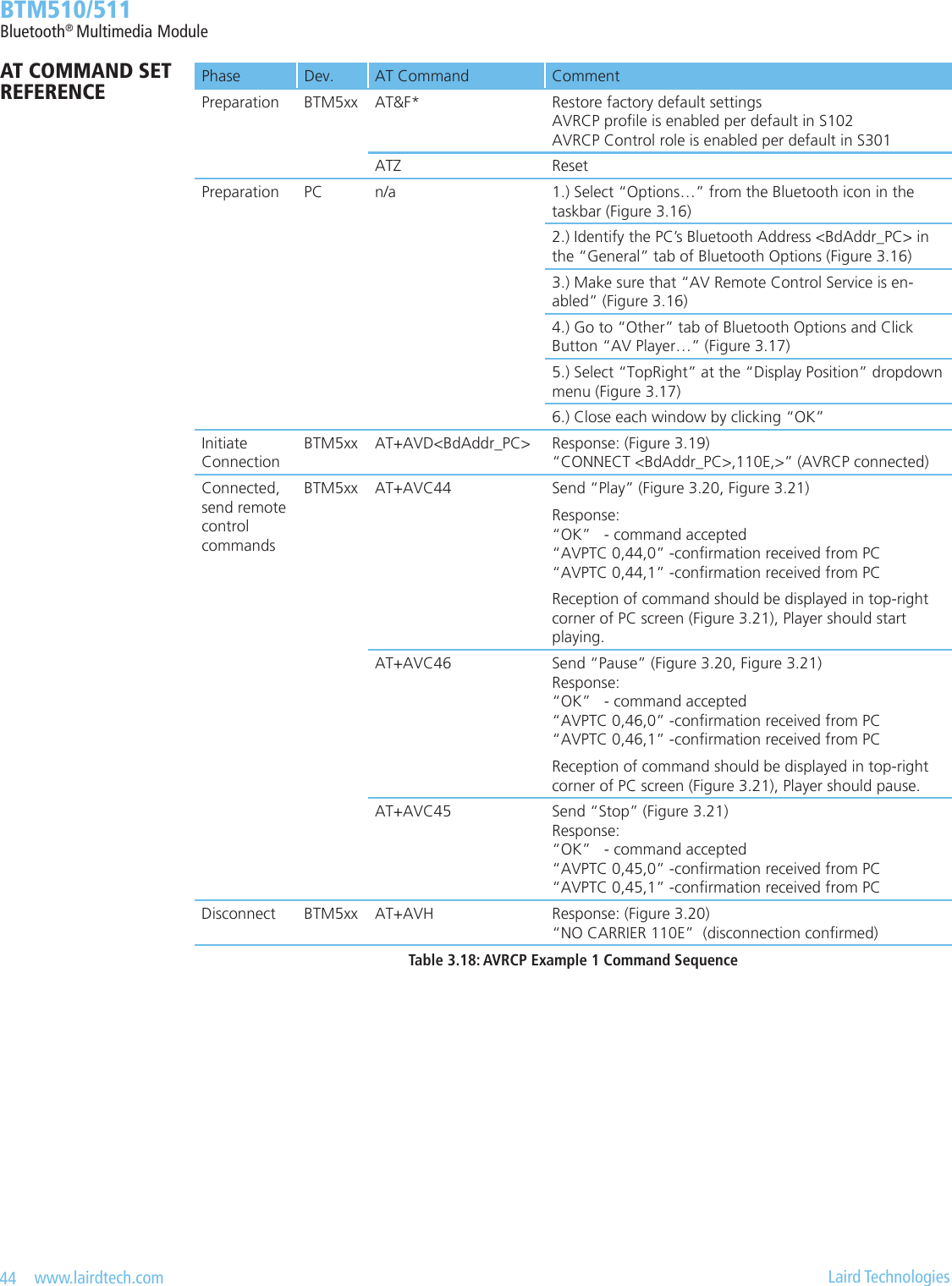
![54 www.lairdtech.com Laird Technologies BTM510/511Bluetooth® Multimedia ModuleHSP Feature Support in HS Support in AGSpecication BTM5xx Specication BTM5xx1. Incoming audio connection M Yes M Yes2. Outgoing audio connection M Yes O Yes3. Audio connection transfer M Yes M Yes4. Remote audio volume control O (1) O(1)M: mandatory O: optional(1) Supported planned for future rmware releaseTable 3.24: Headset Prole supported features on BTM5xx 6.1 Headset role (HS) Headset role is activated by setting ag 0x02 in S102 plus “AT&W” plus “ATZ“. Figure 3.22 shows a block diagram of a headset and how a BTM5xx module would be integrated in hosted operation mode.1 Button Host ControllerSpeaker Microphone BTM5xx [HS]AudioAT command interfaceFigure 3.22 Headset block diagram 6.1.1 Initiate ACL connection from HS AT+HSD<bd_addrhex> Initiate ACL connection from local headset instance to remote device with <bd_addrhex>. The remote device must support the audio gateway role (AG) of the headset prole (HSP). Response: <cr,lf>CONNECT 123456789012,1112,><cr,lf> Or: <cr,lf>NO CARRIER<cr,lf> Or: <cr,lf>ERROR 59<cr,lf> Or: <cr,lf>ERROR 63<cr,lf> After an ACL connection has been established, the module remains in AT command mode. S Register 531 is ignored for HSP connections. An audio connection should be established within short time. The command is “AT+HSB”. 6.1.2 Send “AT+CKPD=200” AT+HSB Send “AT+CKPD=200” to connected audio gateway. This indicates a user initiated action to the gateway, e.g., a button press. Depending on the current audio connection state, the audio gateway will establish or release the audio connection subsequently. Please refer to Table 3.25.AT COMMAND SET REFERENCE](https://usermanual.wiki/Ezurio/511B/User-Guide-1215695-Page-54.png)
![55 www.lairdtech.com Laird Technologies BTM510/511Bluetooth® Multimedia ModuleConnection status Outcome of AT+HSB (“AT+CKPD=200”)ACL connected (ATI63=1) Audio link will be initiated by AG Referred to as “Audio Connection Transfer from AG to HS” in HSPv1.2Audio connected (ATI63=2) Audio link and ACL should be released by the AG, actual outcome depends on AGTable 3.25: Outcome of “AT+HSB” 6.1.3 Release Connection from Headset AT+HSH Release connection from local Headset instance. Audio connection will be released if existing, ACL will be released anyway. A connection release, initiated by the Headset, is not dened in the Headset Prole specication [4]. A prole compliant disconnection is initiated from Headset by sending “AT+CKPD=200” (use “AT+HSB”) to the audio gateway. This command was introduced for the sake of completeness and should be used for testing purposes only. Response: On audio disconnection (optional): <cr,lf>HS”AU0”<cr,lf> On ACL disconnection: <cr,lf>NO CARRIER 1108<cr,lf> 6.1.4 Headset status ATI63 Returns the status of the Headset (HSP) instance: 0 = not connected 1 = ACL connected 2 = Audio connected 6.1.5 Headset asynchronous messages CONNECT <bd_addrhex>,<uuidhex>[,<dir>] An ACL connection to headset has been established. <bd_addrhex> : Bluetooth address of headset device <uuidhex> : “1108” if it was an incoming connection : “1112” if it was an outgoing connection. <dir> : “<”/”>”/”I”/”O”’ optionally indicates the direction (incoming/outgoing), please refer to S331 and section 6, page 85. HS”RING” HS has received a “RING” indication from the connected audio gateway. HS is expected to respond with “AT+CKPD=200” (see “AT+HSB”). HS”AU1” Audio connection (SCO) has been established (= “audio on”). HS”AU0” Audio connection (SCO) has been released (= “audio off”). NO CARRIER 1108 ACL connection to local HS-instance has been released. Please note section 6, page 85.AT COMMAND SET REFERENCE](https://usermanual.wiki/Ezurio/511B/User-Guide-1215695-Page-55.png)
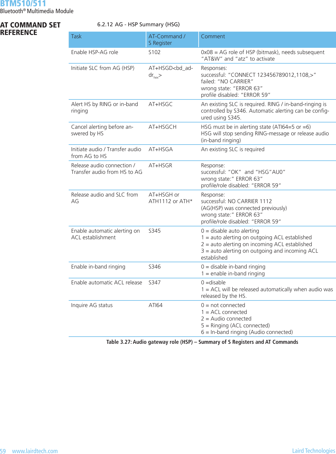
![56 www.lairdtech.com Laird Technologies BTM510/511Bluetooth® Multimedia Module 6.1.6 Headset summaryTask AT-Command / S Register CommentEnable HSP-HS role S102 0x02 = HS role of HSP (bitmask), needs subsequent “AT&W” and “atz” to activate Initiate ACL from headset AT+HSD<bd_addrhex>Responses: successful: “CONNECT 123456789012,1112,>” failed: “NO CARRIER” prole disabled: “ERROR 59” incorrect state: “ERROR 63”Send “Button pressed” (HS) AT+HSB Sends “AT+CPKD=200” to the con-nected gatewayDisconnect from HS AT+HSH / ATH1108 / ATH* For test purposes only, because discon-nection initiated by HS other than send-ing “AT+CKPD=200” to gateway is not dened in HSP specication.Enable “ATH” for HS S332 Enable HS disconnection “ATH1108” and “ATH*” 0 = disabled (default) 1 = enable Should only be enabled for test purpos-es, because disconnection initiated by HS other than sending “AT+CKPD=200” to gateway is not dened in HSP speci-cation.Inquire HS status ATI63 0 = not connected 1 = ACL connected 2 = Audio connectedTable 3.26: Headset role (HSP) – Summary of S Registers and AT Commands 6.2 Audio gateway role (AG-HSP / HSG) Audio gateway role (for HSP) is activated by setting ag 0x08 in S102 plus “AT&W” plus “atz“. Figure 3.23 outlines a block diagram of an audio gateway with a BTM5xx in hosted operation mode.Mobile TerminationHost ControllerAudio routing controllocal speaker, local microphoneBTM5xx [HSG] or [HFG]Audio NetworkAT Command InterfaceTelephone control (set of buttons / keypad / display)Figure 3.23 Audio Gateway block diagramAT COMMAND SET REFERENCE](https://usermanual.wiki/Ezurio/511B/User-Guide-1215695-Page-56.png)
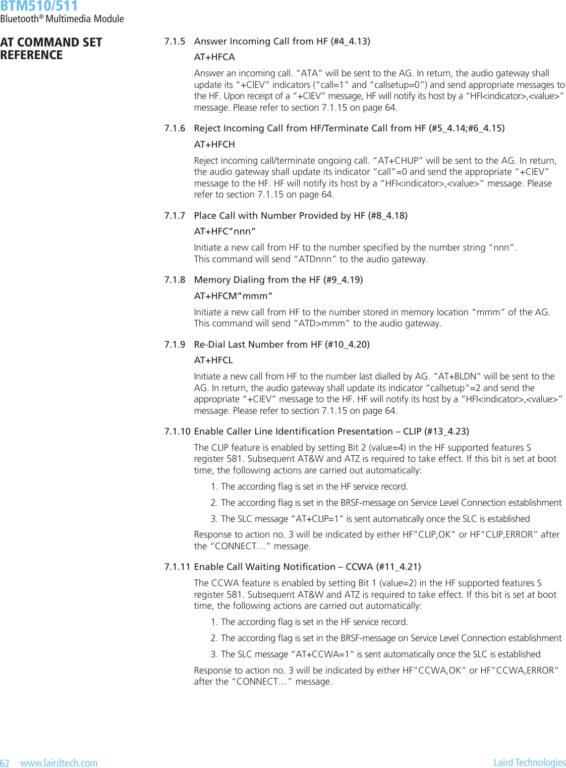
![58 www.lairdtech.com Laird Technologies BTM510/511Bluetooth® Multimedia Module 6.2.7 Enable Automatic Alerting on SLC Establishment S345 S-Register 345 enables automatic alerting on ACL establishment. It contains a bitmask where bit0 corresponds to outgoing ACL connections and bit1 corresponds to incoming ACL connections. If automatic alerting is disabled (S345=0), it can be initiated manually by “AT+HSGC”. 6.2.8 Enable In-Band Ringing S346 In-band ringing is enabled by S-Register 346 (value =1). If disabled (S346=0), the “RING” message is send instead to alert the HS. 6.2.9 Enable Automatic SLC Release S347 If the HSG is in “audio connected” state and the HS initiates an audio release by “AT+CKPD=200” (“Button pressed”), the ACL will be released too if S-Register 347 = 1. If S347=0, it is up to the user to release the ACL manually by “AT+HSGH” or retain the ACL by doing nothing. 6.2.10 AG Status ATI64 Returns the status of the Audio Gateway (HSP) instance: 0 = not connected 1 = ACL connected 2 = Audio connected 5 = Alerting HS by sending “RING” 6 = Alerting HS by in-band ringing 6.2.11 AG Asynchronous Messages CONNECT <bd_addrhex>,<uuidhex>[,<dir>] An ACL connection to headset has been established. <bd_addrhex> : Bluetooth address of headset device <uuidhex> : “1112” if it was an incoming connection : “1108” if it was an outgoing connection. <dir> : “<”/”>”/”I”/”O”’ optionally indicates the direction (incoming/outgoing), please refer to S331 and section 6, page 85 HSG”AU1” Audio connection (SCO) has been established (= “audio on”). HSG”AU0” Audio connection (SCO) has been released (= “audio off”). HSG”B” “AT+CKPD=200” (”Button pressed”) was received from HS. HSG”VGSn” “AT+VGS=n” with was received from HS (speaker gain setting). The valid range for n is 0..15. HSG”VGMn” “AT+VGM=n” with was received from HS (microphone gain setting). The valid range for n is 0..15. NO CARRIER 1112 ACL connection to local AG-instance has been released. Please note section 6, page 85, too.AT COMMAND SET REFERENCE](https://usermanual.wiki/Ezurio/511B/User-Guide-1215695-Page-58.png)
![60 www.lairdtech.com Laird Technologies BTM510/511Bluetooth® Multimedia Module 7. HFP(Hands-FreeProle) The Hands-free prole (HFP) denes how two devices supporting HFP shall interact with each other on a point-to-point basis. The use case for HFP is a hands-free unit that is connected wirelessly to an audio gateway. The audio gateway is typically a cellular phone. The hands-free unit acts as audio input and audio output of the cellular phone and allows to control typical telephony functions to be performed without access to the actual phone. A BTM5xx module is required to be controlled by a host processor using AT commands (hosted operation mode). BTM5xx HFP implementation supports both Hands-free role and Audio gateway role. An AT command beginning with AT+HF... indicates afliation to Hands-free role of HFP. An AT command beginning with AT+HFG…indicates afliation to Audio Gateway role of HFP. Version 1.5 of the hands-free prole is supported [5]. Table 3.28 below shows the feature requirements for this prole and the level of support on BTM5xx. It is highly recommended to download the prole specication [5] in order to understand the procedures related to a certain AT command. For quick navigation, references to [5] are given in this section which follow the syntax: #<Feature>_<Section> With: <Feature> = HFP feature no. in Table 3.28 and Table 3.1 of [5] <Section> = Appropriate Section in [5] Example: #3_4.12 feature no. = 3, section = 4.12HFP Feature Support in HF Support in AGSpecication BTM5xx Specication BTM5xx1. Connection management M Yes M Yes2. Phone status information M Yes M Yes3. Audio Connection handling M Yes M Yes4 Accept an incoming voice call M Yes M Yes5. Reject an incoming voice call M Yes O Yes6. Terminate a call M Yes M Yes7. Audio Connection transfer during an ongoing call M Yes M Yes8. Place a call with a phone number supplied by the HF O Yes M Yes9. Place a call using memory dialing O Yes M Yes10. Place a call to the last number dialed O Yes M Yes11. Call waiting notication O Yes M Yes12. Three way calling O (2) O(2)13. Calling Line Identication (CLI) O Yes M Yes14. Echo cancellation (EC) and noise reduction (NR) O(5) O(5)15. Voice recognition activation O (5) O(5)16. Attach a Phone number to a voice tag O (5) O(5)17. Ability to transmit DTMF codes O (5) M(4)18. Remote audio volume control O (1) O(1)19. Respond and Hold O (2) O(2)20. Subscriber Number Information O Yes M Yes21a. Enhanced Call Status O (2) M Yes21b. Enhanced Call Controls O (2) O(2)M: mandatory O: optional(1) support planned for future AT rmware release (2) support planned for future AT rmware release, but with low priority (3) not planned to be supported for future AT rmware (4) service level signalization only (5) support for service level signalization only planned for future AT rmware releaseTable 3.28: Hands-free Prole supported features on BTM5xxAT COMMAND SET REFERENCE](https://usermanual.wiki/Ezurio/511B/User-Guide-1215695-Page-60.png)
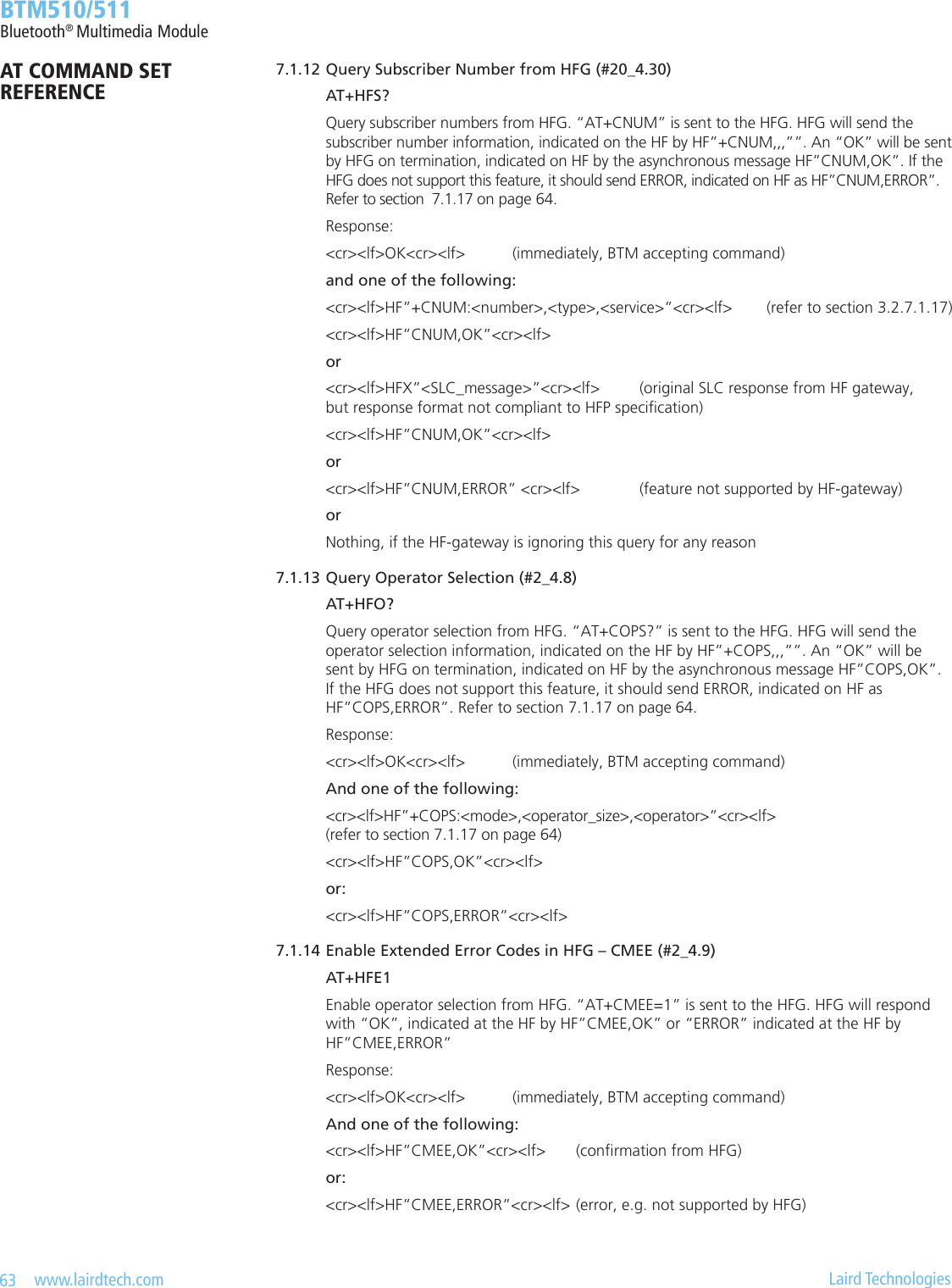
![61 www.lairdtech.com Laird Technologies BTM510/511Bluetooth® Multimedia Module 7.1 Hands-Free Unit Role (HF) Hands-free role is activated by setting ag 0x10 in S102 plus “AT&W” plus “atz“. Figure 3.24 outlines a block diagram with a BTM5xx in hosted operation mode.Figure 3.24 Hands-free unit block diagram 7.1.1 Initiate Service Level Connection (SLC) from HF (#1_4.2) AT+HFD<bd_addrhex> Initiate service level connection (SLC) from local hands-free instance to remote device with <bd_addrhex>. The remote device must support the audio gateway role (AG) of the Hands-free prole (HFP). Response: SLC established: <cr,lf>CONNECT 123456789012,111F,><cr,lf> Failed: <cr,lf>NO CARRIER<cr,lf> Or: <cr,lf>ERROR 59<cr,lf> Or: <cr,lf>ERROR 63<cr,lf> After a SLC connection has been established, the module remains in AT command mode. S Register 531 is ignored for HFP connections. 7.1.2 Initiate Audio Connection from HF (#3_4.11) AT+HFA Initiate audio connection from local Hands-free instance. An existing service level connection is required. Response: Audio on: <cr,lf>HF”AU1”<cr,lf> 7.1.3 Release Audio Connection from HF (#3_4.12) AT+HFR Release audio connection only. The service level connection will be retained. Response: Audio on: <cr,lf>HF”AU0”<cr,lf> 7.1.4 Release Entire Connection from HF (#1_4.3) AT+HFH Release connection from local Hands-free instance. Audio connection will be released if existing, SLC will be released anyway. Response: On audio disconnection: <cr,lf>HF”AU0”<cr,lf> (only if audio connection exists) On SLC disconnection: <cr,lf>NO CARRIER 111E<cr,lf>Telephone control (e.g set of buttons / keypad / display)Host ControllerSpeaker MicrophoneEcho Cancellation BTM5xx [HF]AudioAT command interfaceAT COMMAND SET REFERENCE](https://usermanual.wiki/Ezurio/511B/User-Guide-1215695-Page-61.png)
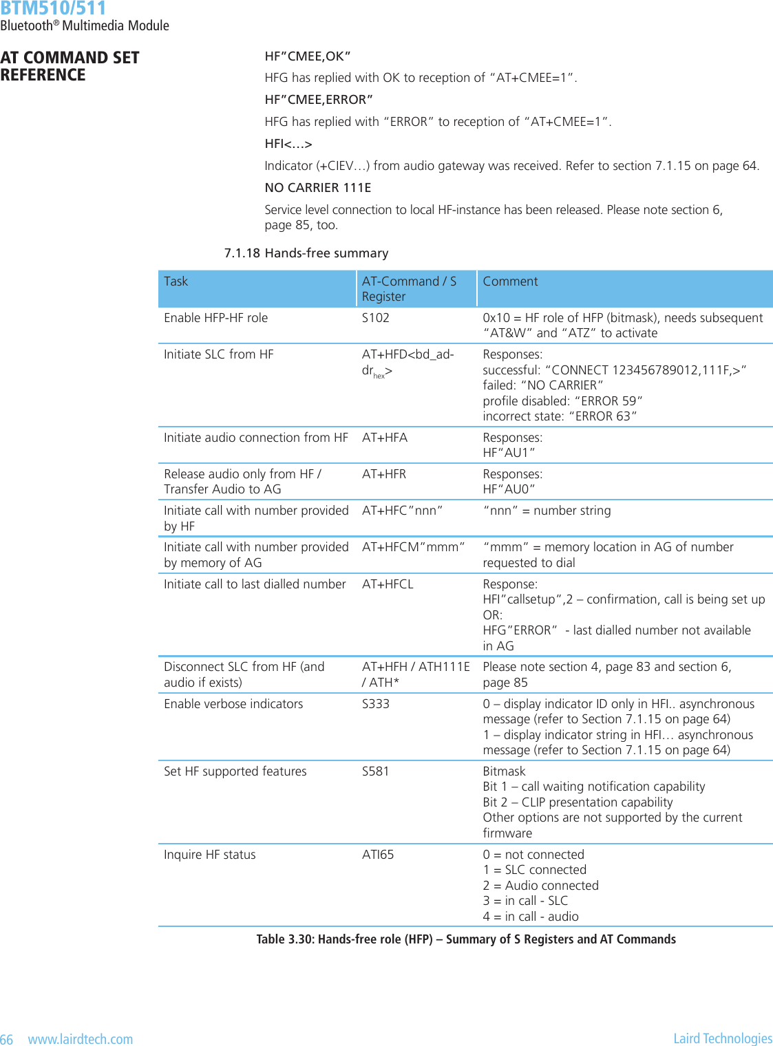
![64 www.lairdtech.com Laird Technologies BTM510/511Bluetooth® Multimedia Module 7.1.15 “+CIEV” Indicators Received from AG (#2) HFI”<indicator_string>”,<val> (S333=1, default) HFI<indicator_id>,<val> (S333=0) Inform the HF-host about a “+CIEV” indicator message received from the connected audio gateway. S-Register 333 enables verbose mode for HFI indicators. Possible indicators are listed in Table 3.29.“+CIEV” Audio Gateway IndicatorHFI indicator_string (S333=1)HFI indicator_id (S333=0)Section in HFP spec. [5]Service “service” 1 4.4Call “call” 2 All call related sectionsCall Setup “callsetup” 3Call held “callheld” 4Signal “signal” 5 4.5Roam “roam” 6 4.6Battery Charge “battchg” 7 4.7Table 3.29: +CIEV indicators in HFI message 7.1.16 Hands-Free Status ATI65 Returns the status of the Hands-free (HFP) instance: 0 = not connected 1 = SLC connected 2 = Audio connected 3 = In call, SLC connected 4 = In call, audio connected 7.1.17 Hands-Free Asynchronous Messages CONNECT <bd_addrhex>,<uuidhex>[,<dir>] A Service level connection to headset has been established and initialized. <bd_addrhex> : Bluetooth address of headset device <uuidhex> : “111E” if it is an incoming connection “111F” if it is an outgoing connection. <dir> : “<”/”>”/”I”/”O”’ optionally indicates the direction (incoming/outgoing), please refer to S331 and section 6, page 85 HF”RING” HF has received a “RING” indication from the connected audio gateway. HF is expected to respond with “ATA” (answer, see “AT+HFCA”) or “AT+CHUP” (see “AT+HFCH”). HF”ERROR” HF has received “ERROR” from the connected audio gateway. This can be due to a request for memory dialling with invalid memory location (AT+HFC>”mmm”) or due to a request to redial the last number (AT+HFDL) but there is no last number available in the AG. HF”AU1” Audio connection (SCO) has been established (= “audio on”). HF”AU0” Audio connection (SCO) has been released (= “audio off”). HF”CLIP,OK” HFG has replied with OK to reception of “AT+CLIP=1” or “AT+CLIP=0”.AT COMMAND SET REFERENCE](https://usermanual.wiki/Ezurio/511B/User-Guide-1215695-Page-64.png)
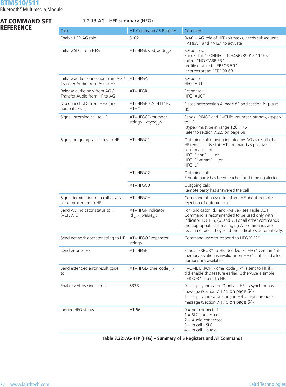
![67 www.lairdtech.com Laird Technologies BTM510/511Bluetooth® Multimedia Module 7.2 Audio Gateway Role (AG-HFP / HFG) Audio gateway role is activated by setting ag 0x40 in S102 plus “AT&W” plus “atz“. Please refer to Figure 3.23 (page 56) for a block diagram of an audio gateway with a BTM5xx in hosted operation mode. Table 3.28 shows the feature requirements for this prole and the level of support on BTM5xx. It is highly recommended to download the prole specication [5] in order to understand the procedures related to a certain AT command. For quick navigation, references to [5] are given in this section which follow the syntax: #<Feature>_<Section> With: <Feature> = HFP feature no. in Table 3.28 and Table 3.1 of [5] <Section> = Appropriate Section in [5] Example: #3_4.12 feature no. = 3, section = 4.12 7.2.1 Initiate Service Level Connection (SLC) from AG (#1_4.2) AT+HFGD<bd_addrhex> Initiate service level connection (SLC) from local audio gateway instance to remote device with <bd_addrhex>. The remote device must support the Hands-free role (HF) of the Hands-free prole (HFP). Response: SLC established: <cr,lf>CONNECT 123456789012,111E,><cr,lf> Failed: <cr,lf>NO CARRIER<cr,lf> Or: <cr,lf>ERROR 59<cr,lf> Or: <cr,lf>ERROR 63<cr,lf> After an SLC connection has been established, the module remains in AT command mode. S Register 531 is ignored for HFP connections. 7.2.2 Initiate Audio Connection from AG (#3_4.11) AT+HFGA Initiate audio connection from local audio gateway instance. An existing service level connection is required. Response: Audio on: <cr,lf>HFG”AU1”<cr,lf> 7.2.3 Release Audio Connection from AG (#3_4.12) AT+HFGR Release audio connection only. The service level connection will be retained. Response: Audio on: <cr,lf>HFG”AU0”<cr,lf> 7.2.4 Release Entire Connection from AG (#1_4.3) AT+HFGH Release connection from local audio gateway instance. An ongoing call will be terminated and a audio connection will be released if existing, SLC will be released anyway. Response: On audio disconnection: <cr,lf>HFG”AU0”<cr,lf> (only if audio connected) On SLC disconnection: <cr,lf>NO CARRIER 111F<cr,lf> Please also refer to Section 6, page 85.AT COMMAND SET REFERENCE](https://usermanual.wiki/Ezurio/511B/User-Guide-1215695-Page-67.png)
![68 www.lairdtech.com Laird Technologies BTM510/511Bluetooth® Multimedia Module 7.2.5 Signal Incoming Call from AG to HF (#4_4.13) AT+HFGC”<number_string>”,<typedec> Signal an incoming call by sending “RING” and “+CLIP:”<number_string>”,<typedec>” to HF periodically. The <number_string> eld represents the phone number of the ringing party. The type eld species the format of the phone number provided, and can be one of the following values: • values 128-143: The phone number format may be a national or international format, and may contain prex and/or escape digits. No changes on the number presentation are required. • values 144-159: The phone number format is an international number, including the country code prex. If the plus sign (“+”) is not included as part of the number and shall be added by the AG as needed. • values 160-175: National number. No prex nor escape digits included. Please refer to the Hands-free Prole Specication [5]. The HF is now expected to answer or to reject the call. Optionally, an incoming call can be answered or rejected at the AG side. 7.2.6 Signal Outgoing Call Status from AG to HF (#8_4.18; #9_4.19; #10_4.20) AT+HFGC1 Signal an outgoing call status by sending “+CIEV:3,2” (callsetup=2) indicator to HF. If an audio connection is not present yet, it will be initiated. An outgoing call can be initiated by HF and is indicated on the AG side by the following asynchronous messages: • HFG”Dnnn” (dial number <nnn> given by headset) • HFG”D>nnn” (dial from AG memory location nnn) • HFG”L” (redial last number) AT+HFGC2 Signal to HF that remote party was reached and is being alerted during an outgoing call setup procedure. “+CIEV:3,3” (callsetup=3) indicator is sent to HF. If the wireless network does not provide an indication of alerting the remote party, the AG may not send this indication. AT+HFGC3 Signal to HF that remote party has answered the call. “+CIEV:2,1” (call=1) and “+CIEV:3,0” (callsetup=0) indicators is sent to HF subsequently. 7.2.7 Signal Termination of a Call from AG to HF (#6_4.15) AT+HFGCH Signal termination of a call by sending “+CIEV:2,0” (call=0) indicator to HF. This command can also be used during a call setup procedure. This would then indicate the interruption / cancellation of the ongoing call setup procedure for any reason. 7.2.8 Sending AG Indicators to HF (“+CIEV…”, #2) AT+HFGI<indicator_iddec>,<valuedec> Send an AG indicator to HF in the form “+CIEV:<indicator_id>,<value>” Table 3.31 lists possible indicators and their value range. If there is no SLC existing and indicator “Service” is set (AT+HFGI1,n), the value is stored in volatile memory in order to be presented during a future SLC initialization procedure. For all other indicators, this command is valid only if a SLC exists. For call management purposes the appropriate commands above (AT+HFGCx) should be used. They will send indicators automatically.AT COMMAND SET REFERENCE](https://usermanual.wiki/Ezurio/511B/User-Guide-1215695-Page-68.png)
![69 www.lairdtech.com Laird Technologies BTM510/511Bluetooth® Multimedia ModuleIndicator name indicator_id Range of value Section in HFP spec. [5]Service 1 0..1 4.4Call 2 0..1 All call related sectionsCall setup 3 0..3Call held 4 0..2Signal 5 0..5 4.5Roam 6 0..1 4.6Battery Charge 7 0..5 4.7Table 3.31: AG indicators for “AT+HFGI..” 7.2.9 Send Operator String to HF (“+COPS…”, #2_4.8) AT+HFGO”<operator_string>” Send network operator string to HF by “+COPS:0,0,”<operator_string>” on SLC. This command shall be used to respond to a “AT+COPS?” request, indicated by the asynchronous message HFG”OP?”. 7.2.10 Send “ERROR” or “+CME ERROR…” to HF AT+HFGE<cme_code> Send “ERROR” to HF if no <cme_code> is given. Required as optional response to HFG”D>nnn” an HFG”L”. If the optional <cme_code> is appended and if extended AG error result codes were enabled by HF (stored internally), the appropriate extended error result code in the form of +CME ERROR: <cme_code> is sent to HF. If <cme_code> is appended but extended error codes have not been enabled by HF, <cme_code> is ignored and only “ERROR” is sent to HF. 7.2.11 Subscriber Number Records (“+CNUM…”, #20_4.30) AT+HFGS=”<number_string>”,<type>,<service> This command adds a subscriber number record to the HFG. The subscriber number is the telephone number of the HFG. It is allowed to have more than one subscriber numbers. All subscriber numbers available should be stored in the HFG immediately after power up of the system. As soon as an SLC to a HF device is established, the HF can query the HFG’s subscriber numbers at any time by sending “AT+CNUM” to the HFG on the SLC. The subscriber number records existing at that time will be sent to the HF automatically then. Subscriber number records are stored in volatile memory. Hence they are lost on reset or power cycle. <number_string> = subscriber number string, characters allowed: 0123456789*#+ABDCTP!W@ <type> = species the format of <number_string> provided, can be one of the following values: • values 128-143: The phone number format may be a national or international format, and may contain prex and/or escape digits. No changes on the number presentation are required. • values 144-159: The phone number format is an international number, including the country code prex. If the plus sign (“+”) is not included as part of the number and shall be added by the AG as needed. • values 160-175: National number. No prex nor escape digits included. <service> = service of this subscriber number, permitted values: 4 – voice 5 – faxAT COMMAND SET REFERENCE](https://usermanual.wiki/Ezurio/511B/User-Guide-1215695-Page-69.png)
![70 www.lairdtech.com Laird Technologies BTM510/511Bluetooth® Multimedia Module Response: <cr><lf>OK<cr><lf> command valid, record added OR: <cr><lf>ERROR 05<cr><lf> syntax or value range error OR: <cr><lf>ERROR 67<cr><lf> maximum number of subscriber number records reached AT+HFGS? This command returns a list of currently available subscriber number records which would be sent to the HF-unit on request (“AT+CNUM” issued by HF on the SLC). Response: For each subscriber number record (if at least one is available): <cr><lf>[<index>]”<number_string>”,<type>,<service><cr><lf> And nally: <cr><lf>OK<cr><lf> command nished With: <index> = current index of the record, required as parameter n for AT+HFGSD<n> <number_string> = subscriber number string <type> = species the format of <number_string>, refer to “AT+HFGS=…” above <service> = service of this subscriber number: 4 – voice 5 – fax AT+HFGSD Delete all subscriber number records in the HFG. Response: <cr><lf>OK<cr><lf> AT+HFGSD<n> Delete subscriber number record with index <n> in the HFG. <n> refers to the index that is displayed on HFGS?. <n> is assumed to be one digit. The index is not xed to a record. If there are higher numbered indexes than the one deleted, the remaining records will get a new index assigned dynamically on HFGS?. Response: <cr><lf>OK<cr><lf> Or: <cr><lf>ERROR 66<cr><lf> record with requested index <n> not available Or: <cr><lf>ERROR 05<cr><lf> syntax error 7.2.12 Audio Gateway (HFP) - Asynchronous Messages CONNECT <bd_addrhex>,<uuidhex>[,<dir>] A Service level connection to headset has been established and initialized. <bd_addrhex> : Bluetooth address of headset device <uuidhex> : “111F” if it is an incoming connection “111E” if it is an outgoing connection. <dir> : “<”/”>”/”I”/”O”’ optionally indicates the direction (incoming/outgoing), please refer to S331 and section 6, page 85AT COMMAND SET REFERENCE](https://usermanual.wiki/Ezurio/511B/User-Guide-1215695-Page-70.png)
![71 www.lairdtech.com Laird Technologies BTM510/511Bluetooth® Multimedia Module HFG”VGS<n>” Speaker gain setting message was received from HF (“+VGS:<n>”) with n = gain [0..15]. HFG”VGM<n>” Microphone gain setting message was received from HF (“+VGM:<n>”) with n = gain [0..15]. HFG”AU1” Audio connection (SCO) has been established (= “audio on”). HFG”AU0” Audio connection (SCO) has been released (= “audio off”). HFG”C” A call has been established and is ongoing. HFG”T” A call has been terminated. HFG”R” Incoming call was rejected by HF. HFG”OP?” Request for network operator string (“AT+COPS?”) received from HF. AG is expected to reply with “+COPS:0,0,<operator_string>” on SLC. Use AT+HFGO”<operator_string>”. HFG”Dnnn” Request from HF to place an outgoing call to phone number provided by HF with <nnn> = number string. The AG is expected to conrm the outgoing call with the command AT+HFGC1. HFG”D>nnn” Request from HF to place an outgoing call using memory dialling with <nnn> = memory location. The AG is expected to either conrm the outgoing call with the command AT+HFGC1 or to respond with AT+HFGE if the memory location is invalid. HFG”L” Request from HF to place an outgoing call using the last number dialled. The AG is expected to either conrm the outgoing call with the command AT+HFGC1 or to respond with AT+HFGE if the last number dialled is not available. HFG”Mn” Request from HF to generate DTMF code <n> towards the telephony network. HFG”CLIP1” Request to activate caller line identication notication in the AG. HFG”CCWA1” Request to activate call waiting notication in the AG. HFG”CMEE1” Request to activate extended AG error result codes in the form +CME ERROR: <err>. NO CARRIER 111F Service level connection to local HFG-instance has been released. Please note section 6, page 85.AT COMMAND SET REFERENCE](https://usermanual.wiki/Ezurio/511B/User-Guide-1215695-Page-71.png)
![73 www.lairdtech.com Laird Technologies BTM510/511Bluetooth® Multimedia Module 8. DUN(Dial-UpNetworkingProle) The Dial-up networking prole (DUN,[6]) denes protocols and procedures for the dial-up networking use case. Scenarios are the usage of a wireless modem or a cellular phone for dial–up Internet connections or the usage of a wireless modem or cellular phone to receive data calls by a PC. There are two roles dened: 1.) Gateway (GW)-This device provides access to the public network (e.g., cellular phone or modem), and role is not supported on BTM. 2.) Data Terminal (DT)-This device uses the dial-up services of the Gateway (e.g., PC), and is supported on BTM. In order to map these roles to the conventional modem structure, the Gateway is referred to as Data Circuit Endpoint (DCE), and the Data Terminal is referred to as Data Terminal Endpoint (DTE). A BTM module is required to be controlled by a host processor using AT commands (hosted operation mode). BTM DUN implementation supports DT role only. The DUN prole belongs to the group of serial stream oriented proles (SSO). The appropriate implications and restrictions are described on page 24. An AT command beginning with AT+DU... indicates afliation to the DUN prole. Service Support in DT Support in GWSpecication BTM Specication BTM1. Data call without audio feedback M Yes M No2. Data call with audio feedback O No O No3. Fax services without audio feedback N/A No N/A No4. Fax services with audio feedback N/A No N/A No5. Voice call N/A No N/A NoM: mandatory O: optional N/A: not applicable 8.1 ProleActivation DUN prole is activated by setting ag 0x04 in S102 plus “AT&W” plus “ATZ“. 8.2 Initiate DUN Connection AT+DUD<bd_addrhex> Initiate ACL connection to remote device with <bd_addrhex>. The remote device must support the DUN prole (HSP). Response: <cr,lf>CONNECT 123456789012,1103,><cr,lf> Or: <cr,lf>NO CARRIER<cr,lf> Or: <cr,lf>ERROR 59<cr,lf> Or: <cr,lf>ERROR 63<cr,lf> Or: <cr,lf> ERROR 65<cr,lf> After an DUN connection has been established, the module changes its mode to the mode dened by S Register 531. The recommended value is S531=0 for a DUN connection (=default). Before initiating a DUN connection, S507 must be set to 2 (ats507=2). This will cause the module to escape from connected mode to command mode by toggling DSR line only. An escape sequence of “^^^” is not compliant with the DUN specication. S507=2 also congures the module for high data throughput. Once the Bluetooth connection is established all data arriving at the UART is transferred to the gateway, hence any AT commands will be transferred directly to the gateway. Now the host can e.g. dial in to the internet provider by “ATD123456” as if directly connected to a serial modem.AT COMMAND SET REFERENCE](https://usermanual.wiki/Ezurio/511B/User-Guide-1215695-Page-73.png)
![74 www.lairdtech.com Laird Technologies BTM510/511Bluetooth® Multimedia Module 8.2.1 Release DUN Connection AT+DUH The module must be in command mode so that AT-commands will be parsed. If the module is in data mode (S531=0, S507=2), toggle DSR line to change into command mode. <cr><lf>OK <cr><lf> will be sent to the host to conrm that that module is in command mode. Toggling DSR means to de-assert (deactivate) an and assert (activate) the DSR line within a time specied by S519 which is 500 ms per default. Hence DSR needs to be asserted at the time of AT+DUD<BdAdd>, if data mode with S531=0 and S507=2 or S507=1 is congured. DSR asserted means a voltage level of logic 0 (0.0 V) at the module pin, because the UART level shifter inverts the signal. Accordingly, DSR de-asserted means a voltage level of logic 1 (3.3 V) at the module pin. Response: On Bluetooth disconnection: <cr,lf>NO CARRIER 1103<cr,lf>Task AT-Command / S Register CommentEnable DUN prole S102 0x04 = DUN (bitmask), needs subsequent “AT&W” and “ATZ” to activateSet up escape mode via DSR, high throughputATS507=2 Needs subsequent “AT&W” if desired as permanent settingInitiate DUN connection AT+DUD<bd_addrhex>Responses: successful: “CONNECT 123456789012,1103,>” failed: “NO CARRIER” prole disabled: “ERROR 59” incorrect state: “ERROR 63”Release DUN connection AT+DUH Responses: successful: “NO CARRIER 1103” prole disabled: “ERROR 59” incorrect state: “ERROR 63”Table 3.33: DUN – Summary of S Registers and AT CommandsHardware Units (BTM510 / 511)This section covers S-Registers and AT-Commands that are related to hardware units of a BTM510 or BTM511 device. For this section, please also refer to the bluecore data sheet [10] for more detailed information. 1. Audio Loopback Mode For testing purposes, an audio loopback mode is available. In mode=1 audio input (ADC) and audio output (DAC) are connected directly. In mode = 2, the stereo audio input signal is fed through the Kalimba DSP with running SBC codec (encoder, decoder) and is directed back to the audio stereo output. Audio Loopback Mode is controlled with the new AT Command “AT+BTL”.Task AT-Command / SRegister CommentSet audio loopback mode AT+BTL<Mode> Mode: 0 = off 1 = on, ADC -> DAC 2 = on, ADC -> DSP -> DACSet sampling rate for Audio Loopback ModeS419 [0..6], default=6 0 = 8 kHz 1 = 11.025 kHz 2 = 16 kHz 3 = 22.050 kHz 4 = 24 kHz 5 = 32 kHz 6 = 44.1 kHzTable 3.39: Audio Loopback AT-commands and S-RegistersAT COMMAND SET REFERENCE](https://usermanual.wiki/Ezurio/511B/User-Guide-1215695-Page-74.png)
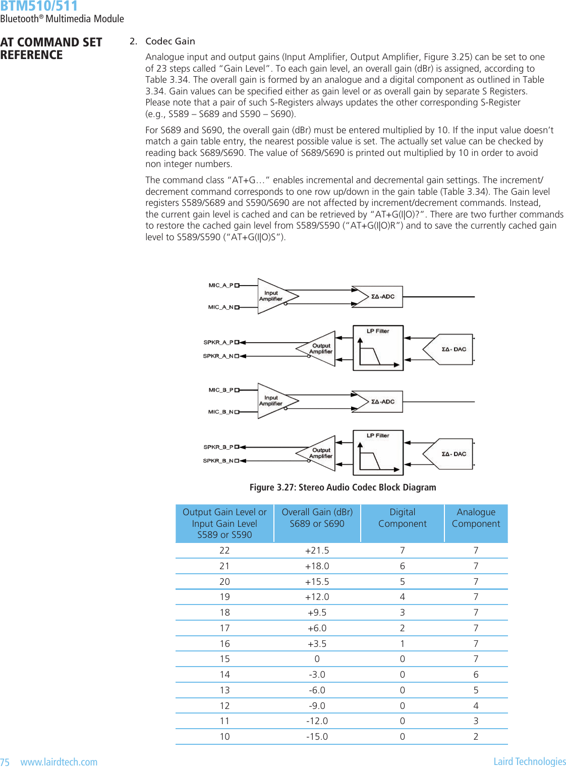
![76 www.lairdtech.com Laird Technologies BTM510/511Bluetooth® Multimedia ModuleOutput Gain Level or Input Gain Level S589 or S590Overall Gain (dBr) S689 or S690Digital ComponentAnalogue Component9 -18.0 0 18 -21.0 0 07 -23.5 15 06 -27.0 14 05 -29.5 13 04 -33.0 12 03 -35.5 11 02 -39.0 10 01 -41.5 9 00 -45.0 8 0Table 3.40: Gain TableTask AT-Command / SRegisterCommentSet output gain level S589 [0..22], default=15See Gain Table; S689 is affected, tooSet output overall gain (dBr) S689 [-450..+215], default=0See Gain Table; value must be entered (and is returned) multiplied by 10; S589 is affected, tooSet input gain level S590 [0..22], default=15See Gain Table; S690 is affected, tooSet input overall gain (dBr) S690 [-450..+215], default=0See Gain Table; value must be entered (and is returned) multiplied by 10; S590 is affected, tooIncrement current output gain levelAT+GOU Error 57 may appear if maximum gain level reachedDecrement current output gain levelAT+GOD Error 58 may appear if minimum gain level reachedQuery current output gain levelAT+GO?Restore current output gain level from S589AT+GORSave current output gain level to S589AT+GOSIncrement current input gain levelAT+GIU Error 57 may appear if maximum gain level reachedDecrement current input gain levelAT+GID Error 58 may appear if minimum gain level reachedQuery current input gain levelAT+GI?Restore current input gain level from S590AT+GIRSave current input gain level to S590AT+GISTable 3.41: Gain Settings AT commands and S-RegistersAT COMMAND SET REFERENCE](https://usermanual.wiki/Ezurio/511B/User-Guide-1215695-Page-76.png)
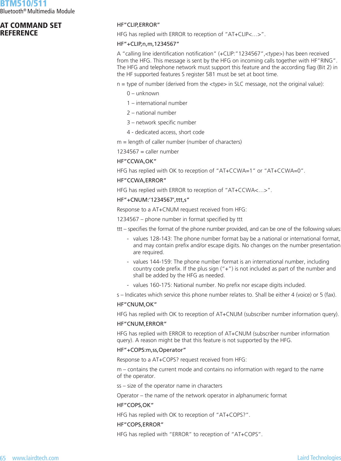
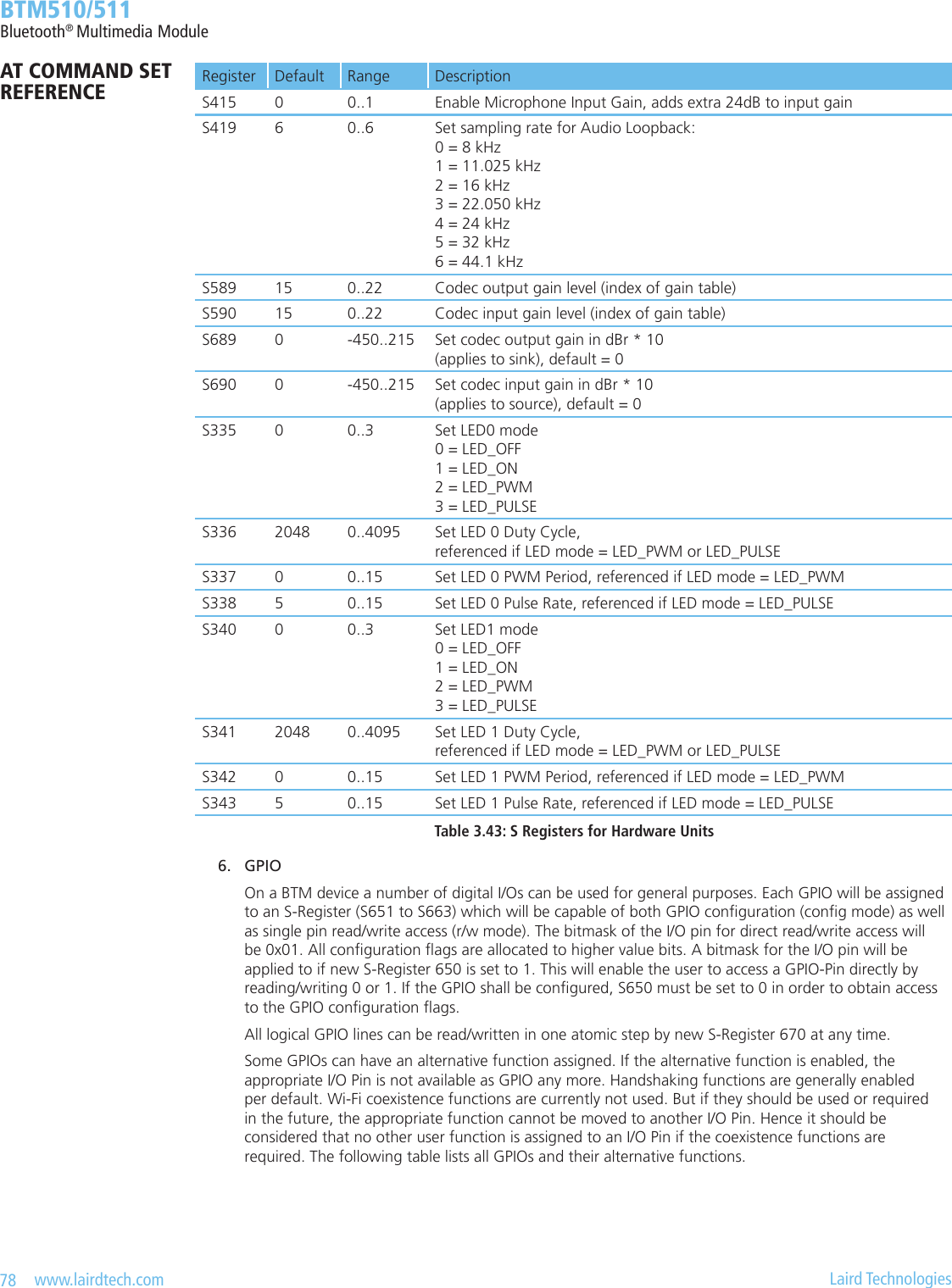
![77 www.lairdtech.com Laird Technologies BTM510/511Bluetooth® Multimedia Module 3. Mic Input Gain A microphone preamplier which adds extra 24dB to input gain, is controlled by S-Register 415. The microphone amplier is enabled by ATS415=1 and disabled by ATS415=0. Refer to Table 3.43. The rst amplier in Figure 3.28 represents the microphone preamplier and the second amplier represents the analogue component of the programmable audio input gain (refer to Table 3.40).Figure3.28:ADCAnalogueAmplierBlockDiagram 4. LED Control The module provides two dedicated output pins for LEDs (LED0, LED1). The following modes are supported: LED_OFF, LED_ON, LED_PWM and LED_PULSE. In LED_PWM mode, the parameters “Duty Cycle” an “PWM Period” can be specied via S-Registers. This enables either to dim the brightness of an LED (PWM Period=0) or to specify blinking with dened on-time in a dened period (PWM Period > blinking visible for the eye). In LED_PULSE mode, the brightness of an LED is modulated. Modulation speed is dened by parameter “Pulse Rate” and maximum brightness is dened by parameter “Duty Cycle”.Task AT-Command / SRegister CommentSet LED 0 mode S335 [0..3], default=0 Mode: 0 = LED_OFF 1 = LED_ON 2 = LED_PWM 3 = LED_PULSESet LED 1 mode S340 [0..3], default=0Set LED 0 Duty Cycle S336 [0..4095], default = 2048 referenced if LED mode = LED_PWM or LED_PULSESet LED 1 Duty Cycle S341 [0..4095], default = 2048Set LED 0 PWM Period S337 [0..15], default = 0 referenced if LED mode = LED_PWMSet LED 1 PWM Period S342 [0..15], default = 0Set LED 0 Pulse Rate S338 [0..15], default = 0 referenced if LED mode = LED_PULSESet LED 1 Pulse Rate S343 [0..15], default = 0Table 3.42: LED S-Registers 5. Hardware Units - S Registers Table 3.43 below gives an overview on S Registers for hardware units except GPIO. For GPIO Registers please refer to Table 3.45.AT COMMAND SET REFERENCE](https://usermanual.wiki/Ezurio/511B/User-Guide-1215695-Page-77.png)
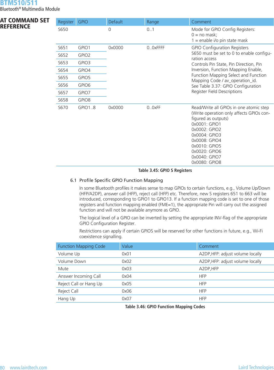
![79 www.lairdtech.com Laird Technologies BTM510/511Bluetooth® Multimedia ModuleGPIO Pin (BTM510/511)Alternative FunctionHandshaking Wi-Fi CoexistenceGPIO1 - BT_Active (1)GPIO2 DCD -GPIO3 DSR -GPIO4 RI -GPIO5 - BT_State/BT_PriorityGPIO6 - Wlan_ActiveGPIO7 - Rf_ActiveGPIO8 DTR -(1) BT_Active = RxEnable OR TxEnableGPIO - Alternative Functions Bit 15 14 13 12 11 10 9 8 7 6 5 4 3 2 1 0function mapping code / av_operation_id Reserved FMS FME INV DIR PSDefault0000000000000000Figure 3.29: GPIO conguration registerField Description0 – PS I/O Pin State – returns the current state of the I/O pin (0/1) when read A write affects the I/0 pin directly if DIR=1 and FME=0.1 – DIR Direction – controls if the I/O pin is an input or an output. 0 input 1 output2 – INV Inversion – controls if the I/O pin is inverted or not. Applies to both pin directions (read and write). 0 not inverted 1 inverted3 – FME Function Mapping Enable – Enables function mapping of the pin. A function mapping code or an av_operation_id must be set in GPIO conguration register [8:15]. The pin will carry out the assigned operation and is not accessible anymore as GPIO. 0 disable function mapping 1 enable function mapping4 – FMS Function Mapping Select – Selects if a Function Mapping Code (see Table 3.46) or an av_operation_id (see Table 3.20) is set in GPIO conguration register [8:15]. Valid only if FME=1. 0 select Function Mapping Code (Table 3.46) 1 select av_operation_id (Table 3.20)[5:7] Reserved[8:15] function mapping code / av_operation_idA Function Mapping Code (FMC, Table 3.46) or an av_operation_id (Table 3.20) is set in this bit eld. The pin is mapped to a prole specic function (A2DP,HFP) or to an AVRCP remote control operation and will carry out the assigned operation. A mapped function does not affect any other ag of the GPIO conguration reg-ister. So, e.g. DIR and INV must be set manually according to the selected function and hardware requirements. Valid only if FME=1. FMS selects function mapping code or av_operation_id. See also section 6.1, on page 80 “Prole specic GPIO function mapping” And section 5.5 on page 53 “AVRCP GPIO Mapping”Table 3.44: GPIO Conguration Register Field DescriptionsAT COMMAND SET REFERENCE](https://usermanual.wiki/Ezurio/511B/User-Guide-1215695-Page-79.png)
![81 www.lairdtech.com Laird Technologies BTM510/511Bluetooth® Multimedia ModuleMiscellaneous 1. SCO / eSCO Audio Link BTM modules provide an AT command to establish an SCO/eSCO audio connection between a pair of BTM modules (or BISM2). This enables the user to create bidirectional audio links independently from a particular Bluetooth prole. The only prerequisite is the existence of a Rfcomm link (serial port prole) between the modules. If this link doesn’t exist, it can be created using AT+SPD<BdAddr>. Please refer to section 2 on page 29. A SCO/eSCO link is intended for bidirectional transmission of speech. The sampling rate is xed to 8 kHz, meaning a usable bandwidth of 3.5 kHz. For SCO there are three packet types dened in the Bluetooth specication [1]: HV1, HV2, HV3. Each of them occupies one slot. They differ in the level of bit error checking. It is recommended to enable all three packet types for SCO links. This will pass the nal decision down to the baseband. There is no retransmission of erroneous SCO packets. For eSCO and basic data rate, there are three packet types dened in the Bluetooth specication [1]: EV3, EV4, EV5. EV3 occupies one slot, EV4 and EV5 can occupy up to three slots each. They differ in the level of bit error checking. It is recommended to enable all three packet types for eSCO links. This will pass the nal decision down to the baseband. eSCO packets involve a CRC code and retransmission of erroneous eSCO packets. Packet types and link types (SCO or eSCO) are negotiated on link setup. A BTM can accept either incoming SCO or eSCO links (S register 584), but not both SCO and eSCO at one time. If the initiating side requests an unsupported link type, the audio link will fail. The initiating BTM module is supposed to request the remaining link type in that case. Table 3.58 lists all AT commands and S-Registers for SCO/eSCO links.Task AT-Command/S-Register CommentInitiate SCO link AT+BTAx x = packet type bitmask, recommended value = 7 1 = HV1 2 = HV2 4 = HV3Initiate eSCO link AT+BTA100x x = packet type bitmask, recommended value = 7 1 = EV3 2 = EV4 4 = EV5Release SCO/eSCO link AT+BTA0 / AT+BTAInitiate SCO/eSCO link AT+BTA8 Link type (SCO/eSCO) and packet types dened by S584.Enable either SCO or eSCO for incoming requests and for AT+BTA8S584 [0..1] 0 = SCO (HV1,HV2,HV3) enabled 1 = eSCO (EV3,EV4,EV5) enabled Only one link type can be enabled at one time.Initiate SCO/eSCO link au-tomatically on each SPP linkS532 [0..7] The recommended value to enable this feature is 7. Value = bitmask for packet type. The link type (SCO/eSCO) is dened by S584. 0 : feature disabled 1 : HV1 (S584=0) or EV3 (S584=1) 2 : HV2 (S584=0) or EV4 (S584=1) 4 : HV3 (S584=0) or EV5 (S584=1)Table 3.58: SCO/eSCO AT-commands and S-RegistersAT COMMAND SET REFERENCE](https://usermanual.wiki/Ezurio/511B/User-Guide-1215695-Page-81.png)
![82 www.lairdtech.com Laird Technologies BTM510/511Bluetooth® Multimedia Module 1.1 SCO / eSCO Asynchronous Messages The following asynchronous messages apply to SCO/eSCO connections. AUDIO ON (SCO) This response is sent to the host when a SCO channel has been established. AUDIO ON (eSCO) This response is sent to the host when a eSCO channel has been established. AUDIO OFF This response is sent to the host when an existing SCO/eSCO channel has been closed. AUDIO FAIL This response is sent to the host when a SCO channel setup fails. This might be caused by the fact that the peer only accepts eSCO connections but a SCO connection was requested or vice versa. Please try to initiate the SCO connection with the remaining link type. 2. Link Key Management On a BTM device, link keys are managed by the AT rmware. Appropriate AT commands are described in on page 24. There is a range of S Registers dening the behavior of automatic link key storage on incoming/outgoing and dedicated/general bonding. 2.1 Dedicated Bonding In BT2.1 specication, “dedicated bonding” is dened as the exchange of link keys between two devices without the intention of establishing a connection immediately. Dedicated bonding is initiated by “AT+BTW<BdAddr>” (initiation of pairing). 2.2 General Bonding In BT2.1 specication, “general bonding” is dened as the exchange of link keys between two devices with the intention of establishing a connection immediately. This is the case if a device tries to connect to another device without existing link key. Hence, pairing (authentication and exchange of link keys) is initiated automatically prior to the connection. General bonding is initiated by a connection requesting AT command if there is no link key for the peer device existing. Such AT commands are: “AT+SPD<BdAddr>”, “AT+APD<BdAddr>”, “AT+AVD<BdAddr>”, ”AT+HSD<BdAddr>”, “AT+HSGD<BdAddr>”, “AT+HFD<BdAddr>”, “AT+HFGD<BdAddr>”, “AT+DUD<BdAddr>” 2.3 Automatic storage of link keys Four S Registers dene the automatic storage of link keys in the trusted device list, depending on incoming/outgoing and general/dedicated bonding. Please see Table 3.59.Task S-Register CommentAutomatic link key storage on dedicated bonding outgoing (DBO)S325 [0..1] 0 = do not store (cache only) 1 = store automatically (default) identical with S538Automatic link key storage on general bonding outgoing (GBO)S326 [0..1] 0 = do not store (cache only) 1 = store automatically (default)Automatic link key storage on dedicated bonding incoming (DBI)S327 [0..1] 0 = do not store (cache only) 1 = store automatically (default)Automatic link key storage on general bonding incoming (GBI)S328 [0..1] 0 = do not store (cache only) 1 = store automatically (default)Table 3.59: Automatic storage of link keys 3. ProleConnectionStatus The connection status of a prole can be queried by an ATI-Command. This might be helpful in order to decide whether to disconnect all connected proles (via ATH*) or a certain one. For details please see Table 3.60.AT COMMAND SET REFERENCE](https://usermanual.wiki/Ezurio/511B/User-Guide-1215695-Page-82.png)
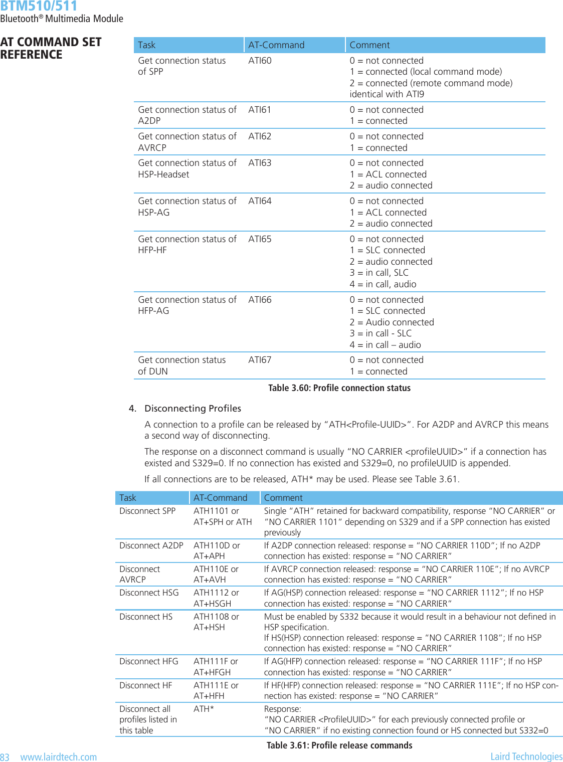
![84 www.lairdtech.com Laird Technologies BTM510/511Bluetooth® Multimedia Module 5. Legacy Response Format (BISM2) Some BISM2 responses have been slightly changed on BTM modules in order to provide enhanced functionality. If required, a BISM2 compatible response format can be enabled by S Register 329. Table 3.63 shows the implications of enabled/disabled legacy response format.Task S-Register CommentEnable legacy response format (BISM2 compatible)S329 [0..1] 0 = disabled (default) 1 = enabledTable 3.62: Enabling/Disabling legacy response formatCommand Legacy response format enabled (S329=1)Legacy response format disabled (S329=0)“AT+SPH”;”ATH1101” Response = “NO CARRIER” If SPP was connected, response = “NO CARRIER 1101” If SPP was not connected, re-sponse = “NO CARRIER”“AT+APH”;”ATH110D” Response = “NO CARRIER” If A2DP was connected, response = “NO CARRIER 110D” If A2DP was not connected, response = “NO CARRIER”“AT+AVH”;”ATH110E” Response = “NO CARRIER” If AVRCP was connected, re-sponse = “NO CARRIER 110E” If AVRCP was not connected, response = “NO CARRIER”“AT+HSH”;”ATH1108” Response = “NO CARRIER” If HS instance was connected, response = “NO CARRIER 110E” If HS instance was not connected, response = “NO CARRIER”“AT+HSGH”;”ATH1112” Response = “NO CARRIER” If HSG instance was connected, response = “NO CARRIER 1112” If HSG instance was not connect-ed, response = “NO CARRIER”“AT+HFH”;”ATH111E” Response = “NO CARRIER” If HF instance was connected, response = “NO CARRIER 111E” If HF instance was not connected, response = “NO CARRIER”“AT+HFGH”;”ATH111F” Response = “NO CARRIER” If HFG instance was connected, response = “NO CARRIER 111F” If HFG instance was not connect-ed, response = “NO CARRIER”“AT+DUH”;”ATH1103” Response = “NO CARRIER” If DUN was connected, response = “NO CARRIER 1103” If DUN was not connected, re-sponse = “NO CARRIER”Table 3.63: Implications of S329AT COMMAND SET REFERENCE](https://usermanual.wiki/Ezurio/511B/User-Guide-1215695-Page-84.png)
![85 www.lairdtech.com Laird Technologies BTM510/511Bluetooth® Multimedia Module 6. UUIDs in “CONNECT”/”NO CARRIER” Messages In proles where functionality and command set differs between both possible roles (asynchronous proles), role indicating UUIDs are used in the “CONNECT” and “NO CARRIER” messages. HSP and HFP are asynchronous proles. A2DP and AVRCP are treated as synchronous proles because only one prole instance with one role selected can be initialised currently. Therefore, a common UUID is used indicating the prole only, but not the role. In a message “CONNECT <bd_addrhex>,<UUID>”, UUID is the prole/role the connection is made to. Hence for an outgoing connection, UUID indicates the remote device’s prole/role. If it is an incoming connection, UUID indicates the local device’s prole/role UUID. Hence, role indicating UUIDs presented in a “CONNECT” message will be equal on both ends of a connected pair. In a message “NO CARRIER <UUID>”, UUID represents the local prole/role UUID. Hence for an asynchronous prole, role-indicating UUIDs will differ on both ends of a previously connected pair. Table 3.64 Gives an overview of currently used UUIDs on BTM devices.UUID (hex) Prole/Role Role indication Comment1101 SPP No Synchronous prole1108 HSP – HS Yes Headset role (Headset prole)110D A2DP No Common UUID for source and sink role110E AVRCP No Common UUID for controller and target role1112 HSP – AG Yes Audio gateway role (Headset prole)111E HFP – HF Yes Hands-free role (Hands-free prole)111F HFP – AG Yes Audio gateway role (Hands-free prole)Table 3.64: UUIDs used in BTM5xx CONNECT/NO CARRIER messages There is an option to append a direction indicator to a connect message. This enables the host to distinguish an incoming connection from an outgoing connection based on the “CONNECT“ message. The direction indicator only applies to role indicating UUIDs and if S329=0. The direction indicator is congured by S register 331, please refer to Table 3.65.S331 Meaning ExampleIncoming connection Outgoing connection0 Disabled CONNECT 0123456789AB,1108CONNECT 0123456789AB,11081 Character style, ‘I’ or ‘O’ CONNECT 0123456789AB,1108,ICONNECT 0123456789AB,1108,O2 (default) Symbol style, ‘<’ or ‘>’ CONNECT 0123456789AB,1108,<CONNECT 0123456789AB,1108,>Table 3.65: Examples for direction indication in “CONNECT” messages 7. Page Scan / Inquiry Scan Interval and Window Page scanning means being connectable. Inquiry scanning means being discoverable. With the following S registers the power consumption of the BTM can be inuenced. However, lower power consumption means longer connection establishment time and longer time until a BTM is discovered by other devices. The page scan window denes the time for the module to look out for incoming connection requests (paging). The inquiry scan window denes the time for the module to look out for incoming inquiry requests (device discovery). If the module is both connectable and discoverable (512=4 or AT+BTP issued), it will mutually do page scanning and inquiry scanning as shown in Figure 3.33. If connectable only, the module will perform page scanning only (repeatedly) and if discoverable only, then the module will perform page scanning only. S register 508 denes the page scan interval in ms, range is [11..2250]. S register 509 denes the page scan window in ms, range is [11..2250]. S register 510 denes the inquiry scan interval in ms, range is [11..2250]. S register 511 denes the inquiry scan window in ms, range is [11..2250].AT COMMAND SET REFERENCE](https://usermanual.wiki/Ezurio/511B/User-Guide-1215695-Page-85.png)
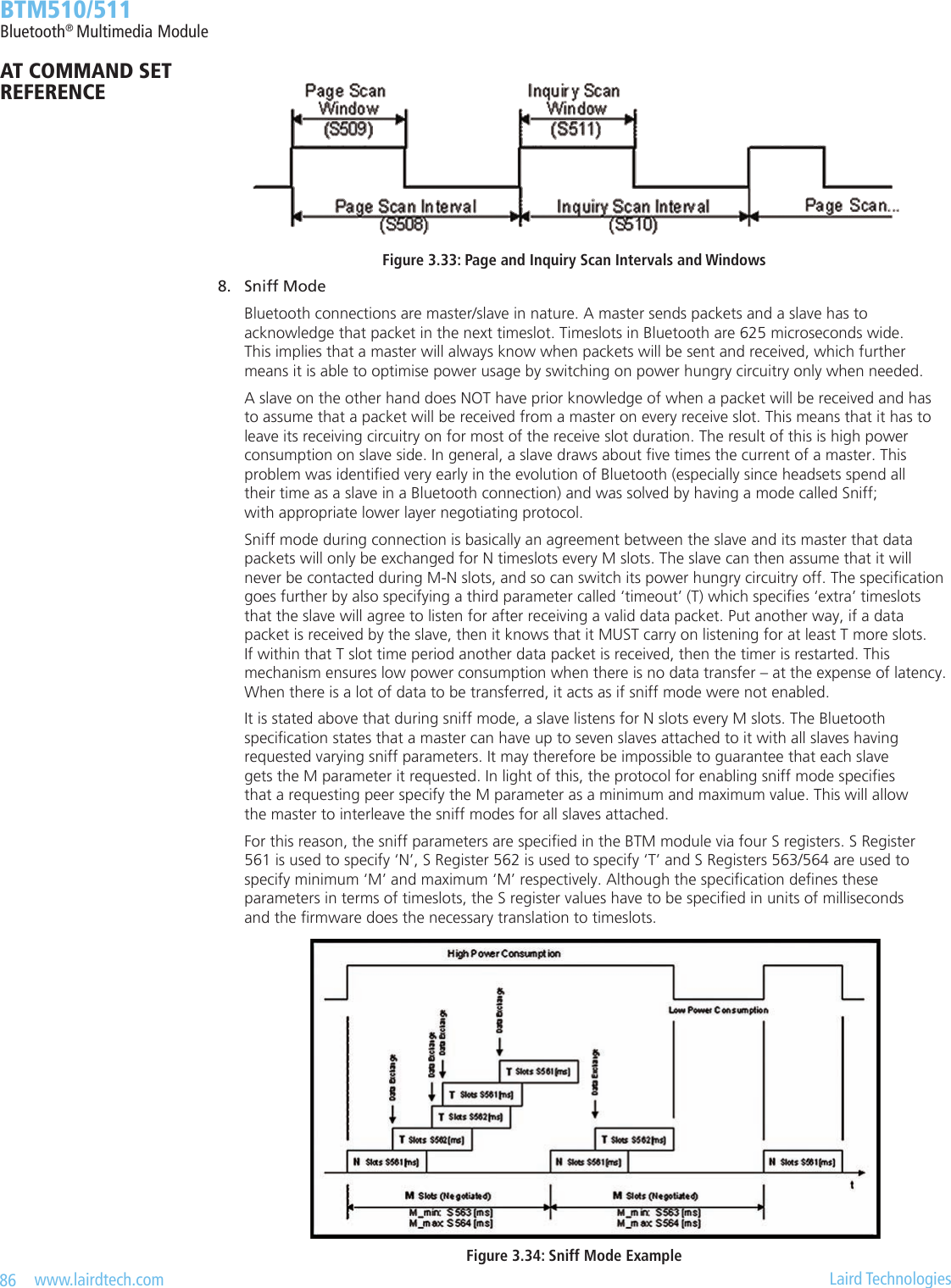
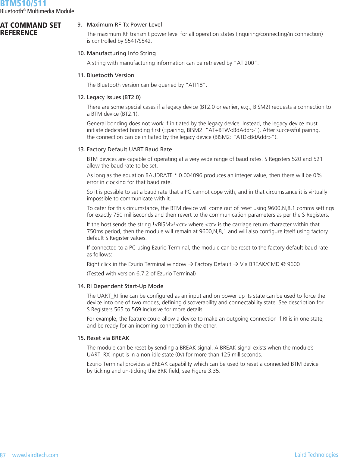
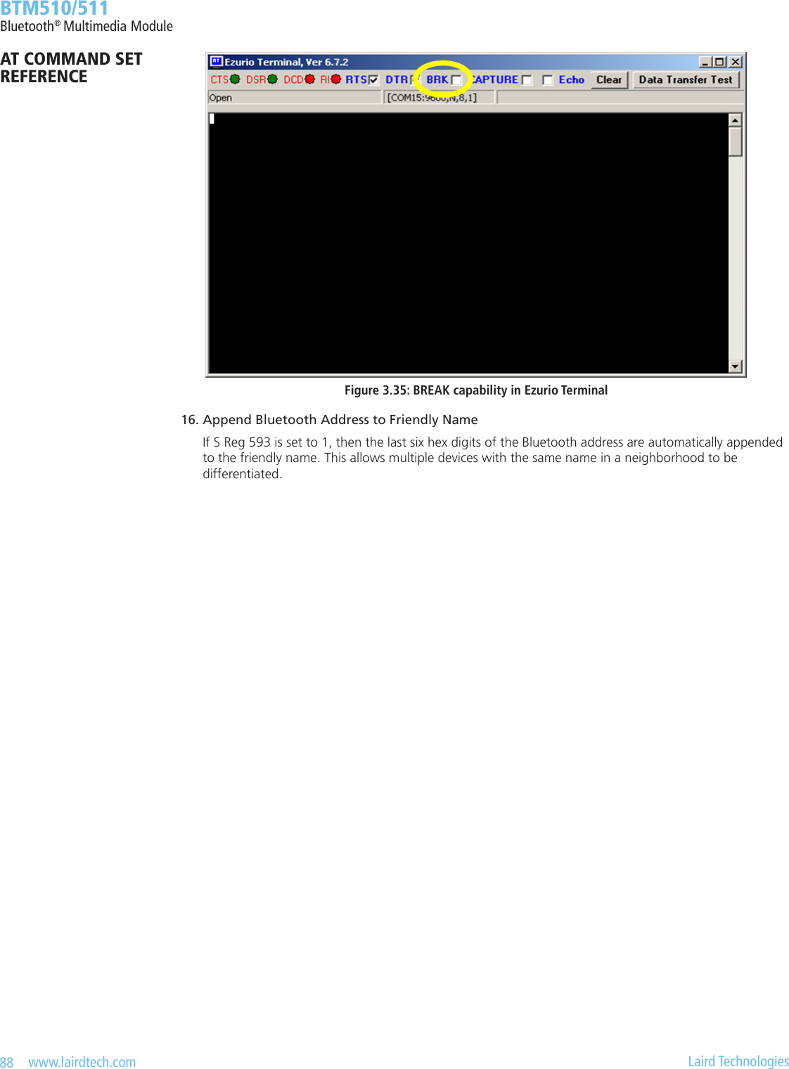
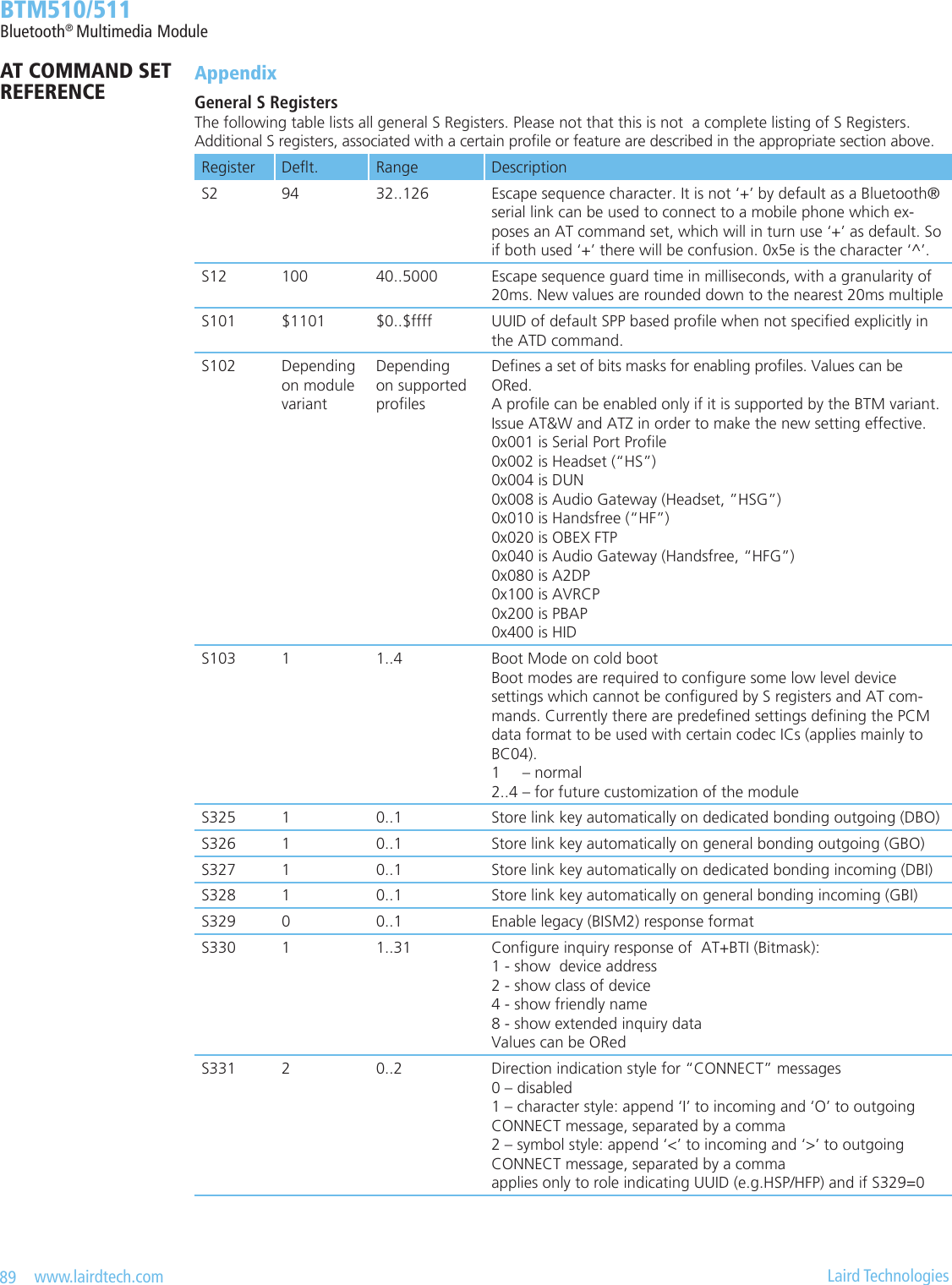
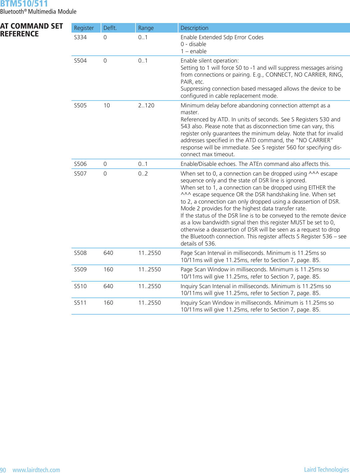
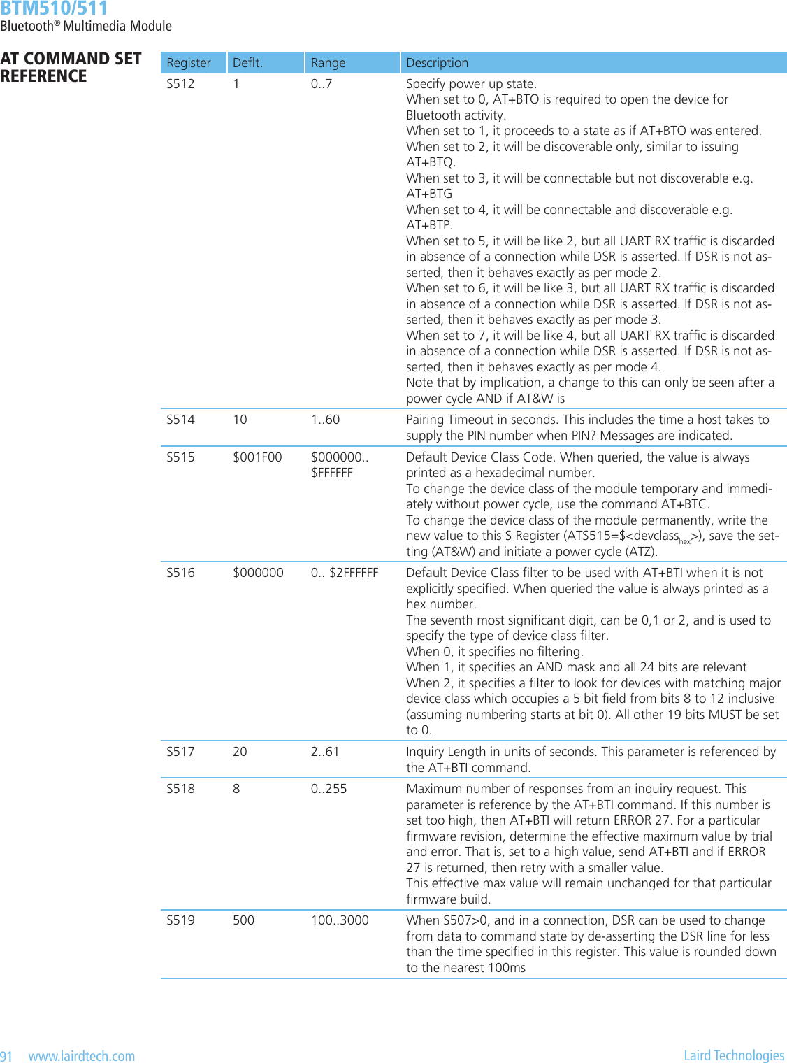
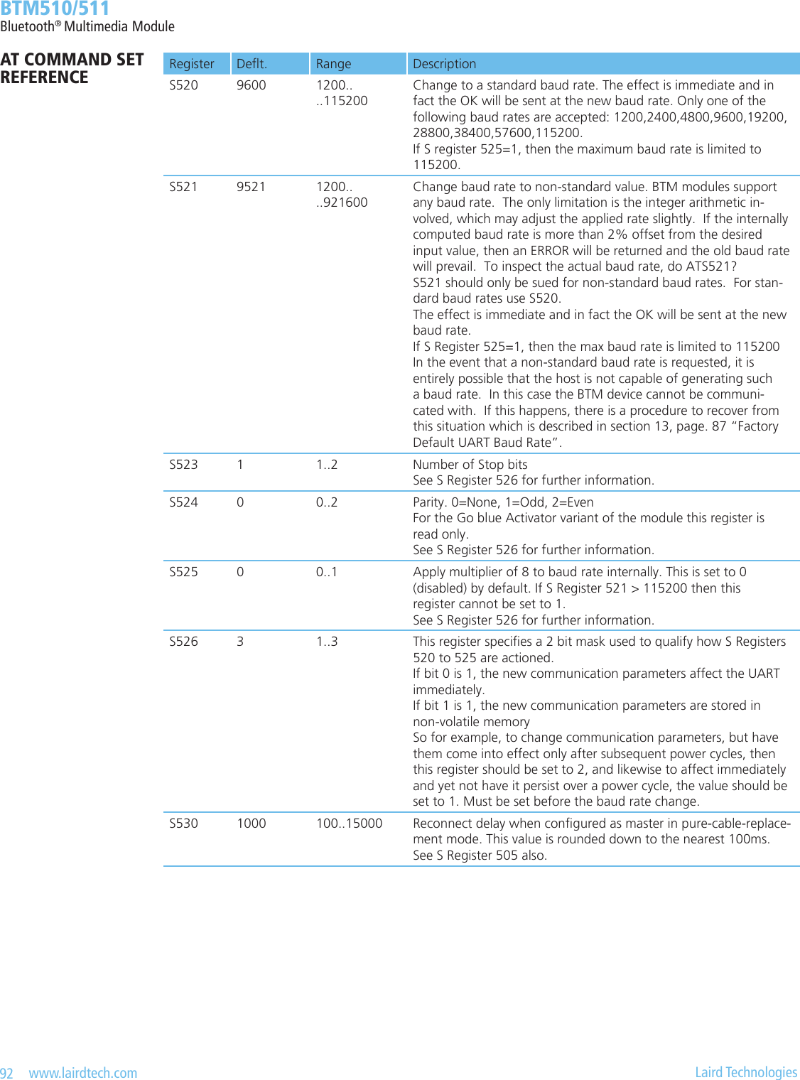
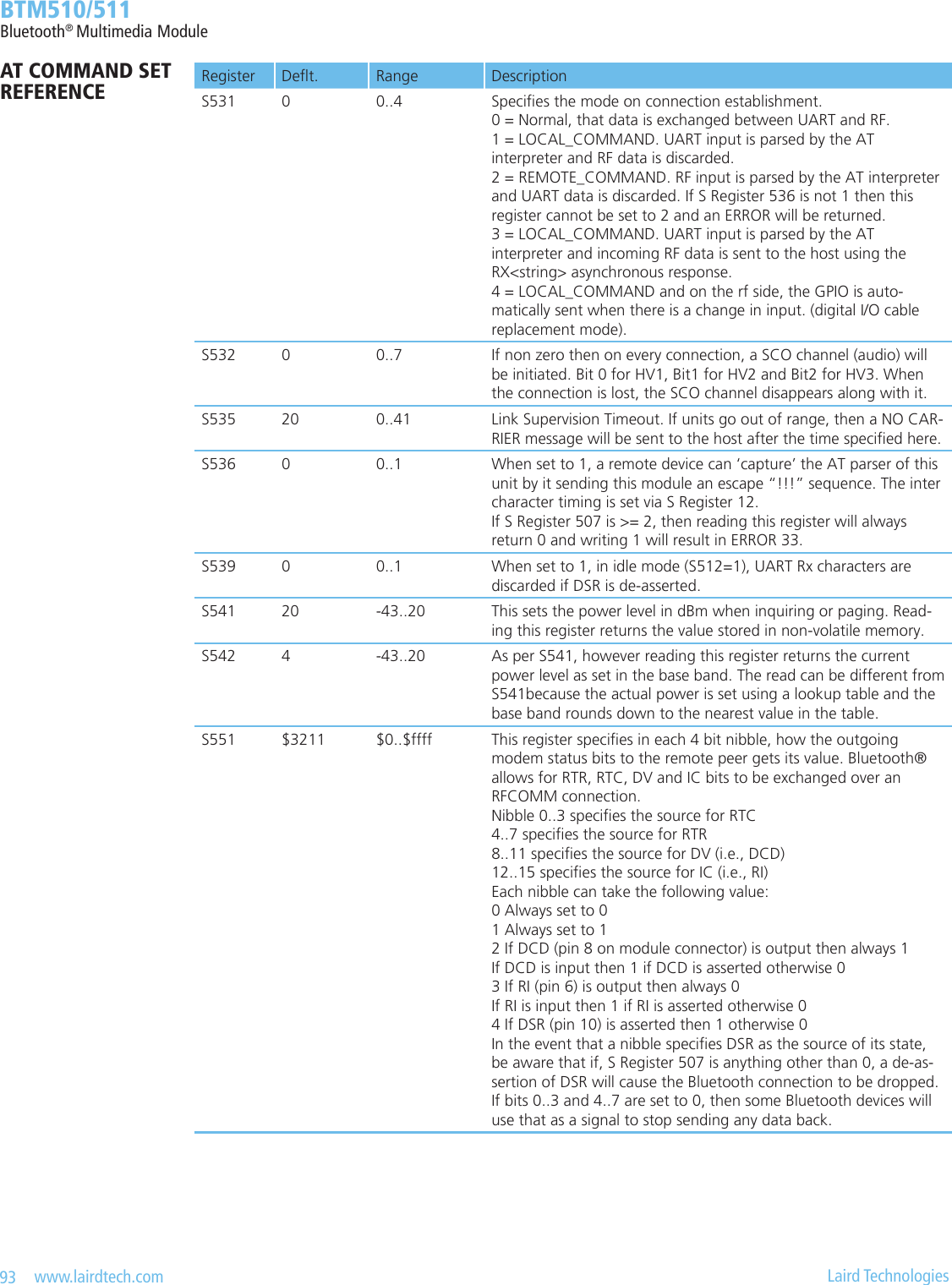
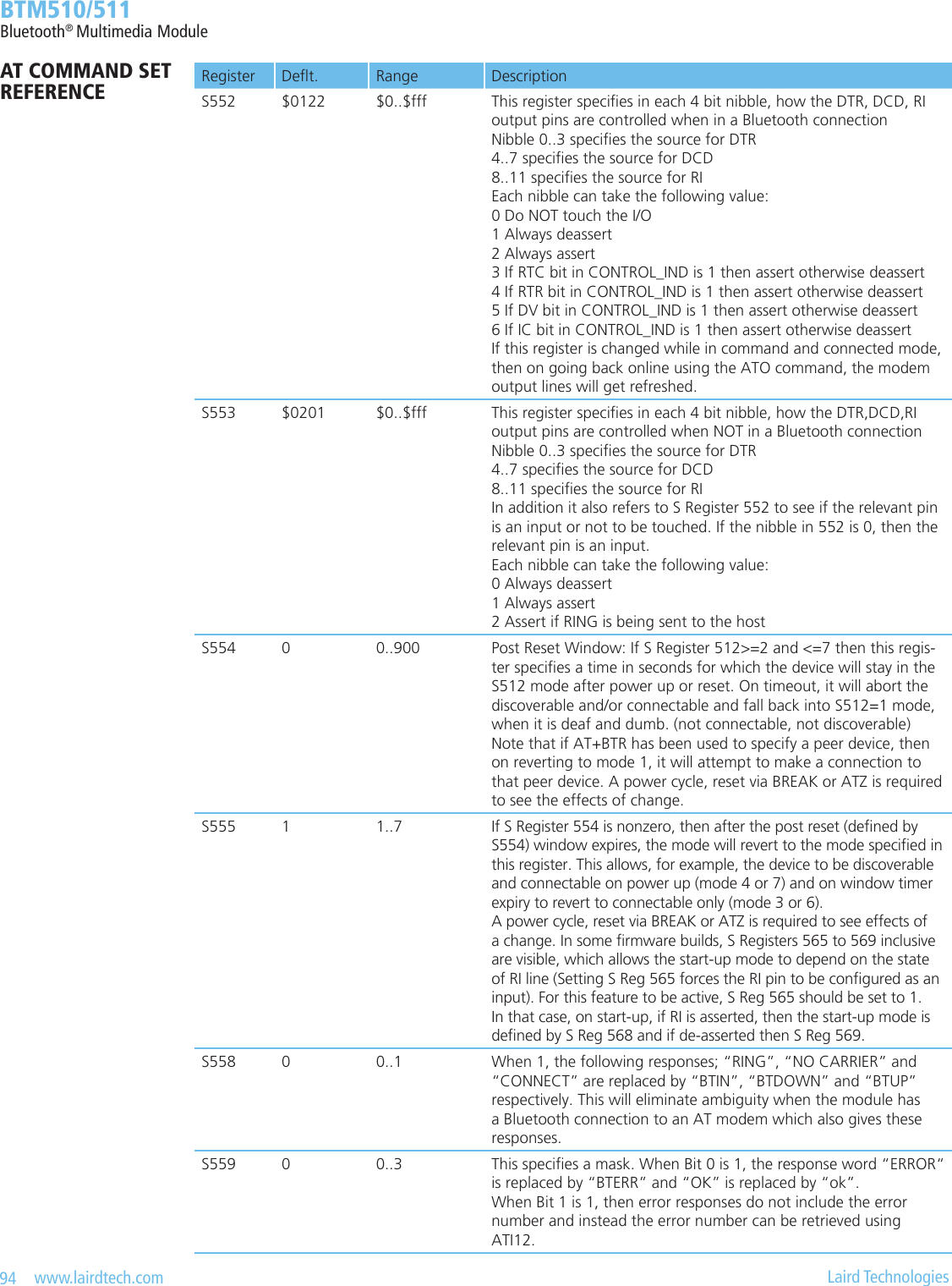
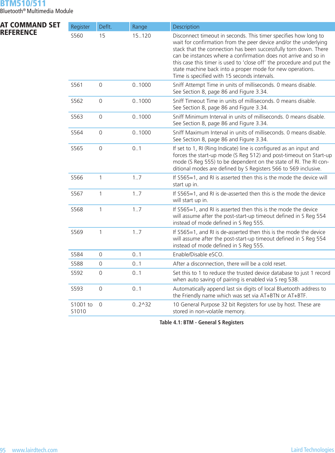
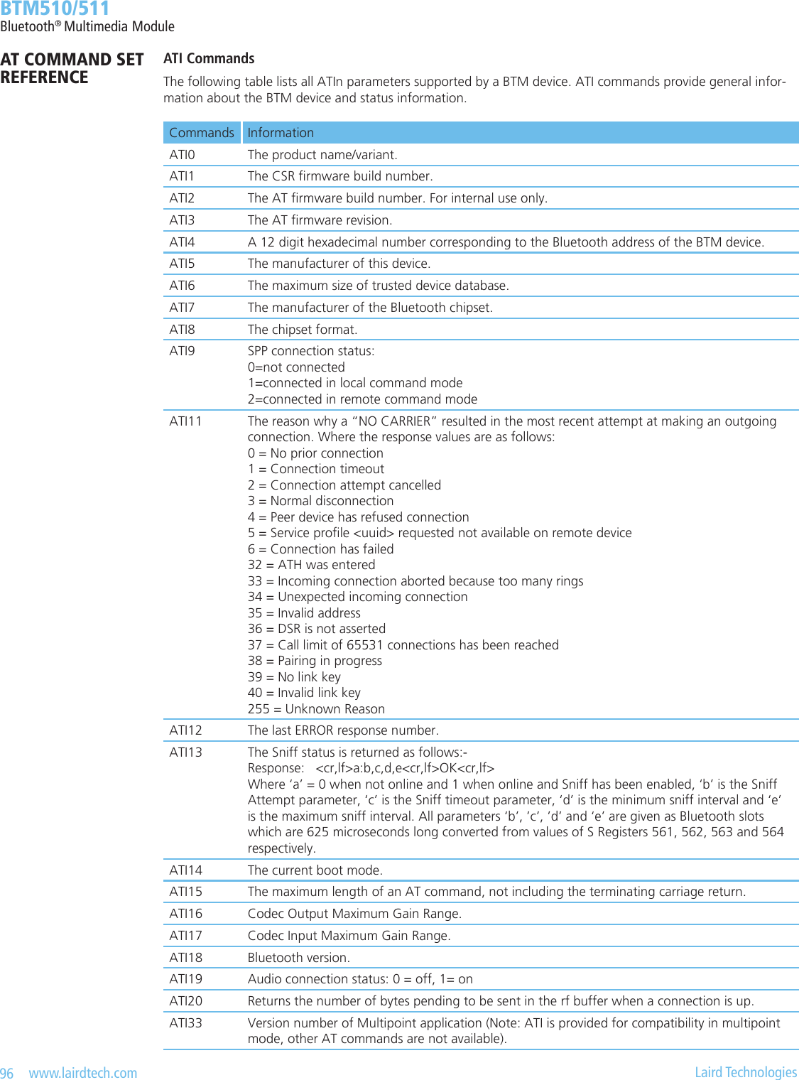
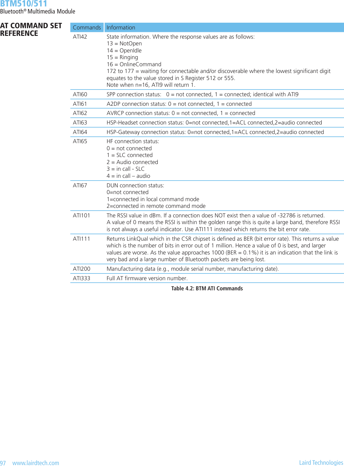
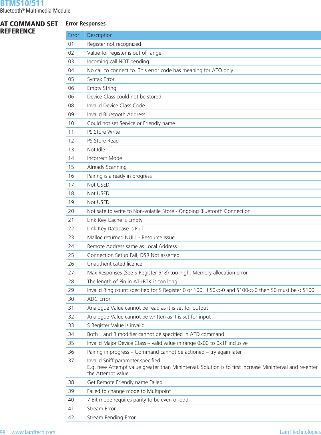
![99 www.lairdtech.com Laird Technologies BTM510/511Bluetooth® Multimedia ModuleError Description43 Unknown Audio Gateway Command44 Busy, try later45 Command or operation not allowed46 No A2DP role has been set (see S register 300)47 No AVRCP role has been set (see S register 301)48 No AVRCP category has been set (see S register 302)49 No AVRCP control connection50 No A2DP or AVRCP connection currently incoming51 Invalid operation ID (AVRCP)52 Wrong AVRCP role53 Command disabled by S-Register 31054 No manufacturing information available55 Audio resource error56 Invalid UUID57 Maximum gain level reached58 Minimum gain level reached59 Prole or role not enabled60 Prole under construction61 Unknown Headset command62 Unknown Hands-free command63 Incorrect state64 Unknown DUN command65 UART resource errorTable 4.3: BTM Error ResponsesList of UUIDsTable 4.4 gives a list of selected UUIDs. For a complete list refer to the “Assigned Numbers – Service Discovery (SDP)” document [3] by the Bluetooth SIG.UUID Mnemonic / Prole Role 0x1101 Serial Port Prole (SPP) -0x1102 LAN access using PPP -0x1103 Dial-up Networking (DUN) -0x1105 OBEX Object Push -0x1106 OBEX File Transfer -0x1108 Headset Prole (HSP) Headset0x110A A2DP Audio Source0x110B A2DP Audio Sink0x110C AVRCP Remote Target0x110D A2DP -0x110E AVRCP -0x110F AVRCP Remote Controller0x1112 Headset Prole Audio Gateway0x111E Hands-free Prole (HFP) Hands-free unit0x111F Hands-free Prole (HFP) Audio GatewayTable 4.4: Selected UUIDsAT COMMAND SET REFERENCE](https://usermanual.wiki/Ezurio/511B/User-Guide-1215695-Page-99.png)
![100 www.lairdtech.com Laird Technologies BTM510/511Bluetooth® Multimedia ModuleReferences[1] “Bluetooth Specication Version 2.1 + EDR [vol3]”, 26 July 2007 http://www.bluetooth.com/Bluetooth/Technology/Building/Specications/ (click on “Core Specication v2.1 + EDR”)[2] “Advanced Audio Distribution Prole Specication” Rev. V12, 16/04/2007 http://www.bluetooth.com/Bluetooth/Technology/Works/A2DP.htm (link at bottom of page “Need more? View the Advanced Audio Distribution Prole (A2DP) 1.2”)[3] “Audio/Video Remote Control Prole” Revision 1.0 22/05/2003 http://www.bluetooth.com/Bluetooth/Technology/Building/Specications/ (click on “Audio/Video Remote Control Prole 1.0”) http://www.bluetooth.com/Bluetooth/Technology/Works/AVRCP.htm (alternative, but only revision 1.3 of the AVRCP spec is available, therefore go to link at bottom of page “Need more? View the Audio/Video Remote Control Prole (AVRCP) 1.3”)[4] “Headset Prole” Revision V12r00, 18/12/2008 http://www.bluetooth.com/Bluetooth/Technology/Works/HSP.htm (link at the bottom of page “Need more? View the Headset Prole (HSP)”)[5] “Hands-free Prole 1.5” Revision V10r00, 25/11/2005 http://www.bluetooth.com/Bluetooth/Technology/Works/HFP.htm (link at the bottom of page “Need more? View the Hands-Free Prole (HFP) 1.5”)[6] “Dial-Up Networking Prole” Version 1.1 http://www.bluetooth.com/Bluetooth/Technology/Works/DUN.htm (link at the bottom of page “Need more? View the Dial-up Networking Prole (DUN)”)[7] “Serial Port Prole“ Specication http://www.bluetooth.com/Bluetooth/Technology/Works/SPP.htm (link at the bottom of page “Need more? View the Serial Port Prole (SPP)”)[8] “Bluetooth Assigned Numbers” http://www.bluetooth.com/Bluetooth/Technology/Building/Specications/ select “Items per page: ALL”, go to end of page, there click on “Assigned Numbers – Baseband”, for a complete list of Prole UUIDs: click on “Assigned Numbers – Service Discovery”[9] Class of Device Generator: this link might be helpful for creating a particular CoD http://bluetooth-pentest.narod.ru/software/bluetooth_class_of_device-service_generator.html Caution: this tool allows selection of more than one minor device classes, so make sure that only one minor device class is select and verify the result with [8] anyway.[10] “Bluecore 5-Multimedia External” Data Sheet, Cambridge Silicon Radio (CSR) http://www.csrsupport.com (log in or new account required)[11] “Bluecore 4 External” Data Sheet, Cambridge Silicon Radio (CSR) http://www.csrsupport.com (log in or new account required)AT COMMAND SET REFERENCE](https://usermanual.wiki/Ezurio/511B/User-Guide-1215695-Page-100.png)