Ezurio 520B Bluetooth Multi-Media Module User Manual
Ezurio Ltd Bluetooth Multi-Media Module
UserManual.wiki
>
Ezurio
>
520B User Manual
>
User Manual
Contents
1.
User Manual
2.
FCC statement insert
3.
Manual
4.
Manual FCC statement
User Manual
Navigation menu
Upload a User Manual
Namespaces
Wiki Guide
HTML
PDF
Info
Views
User Manual
Discussion / Help
Navigation

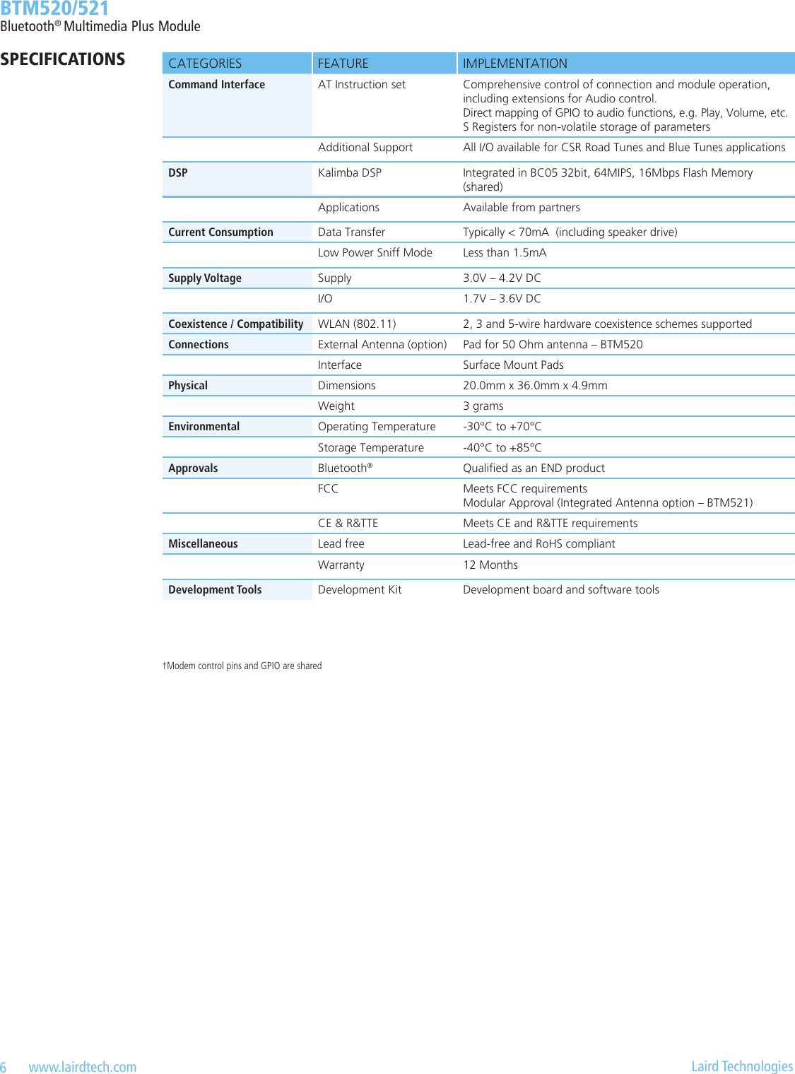
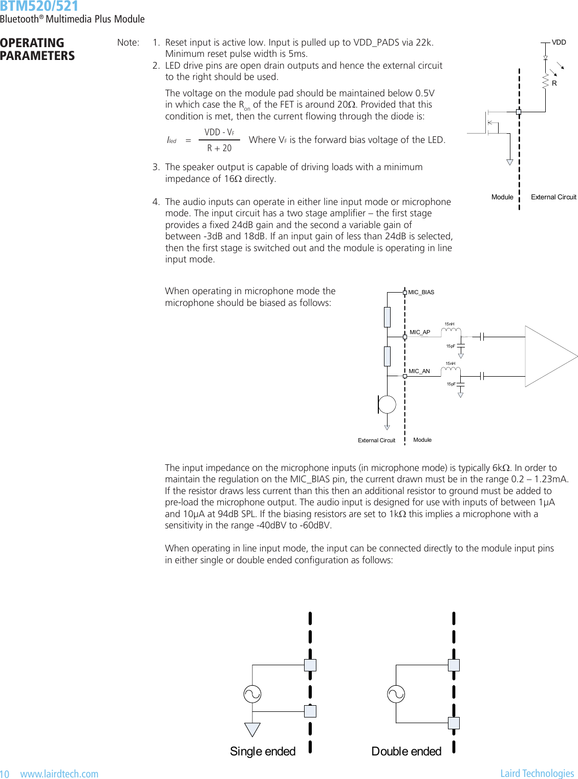
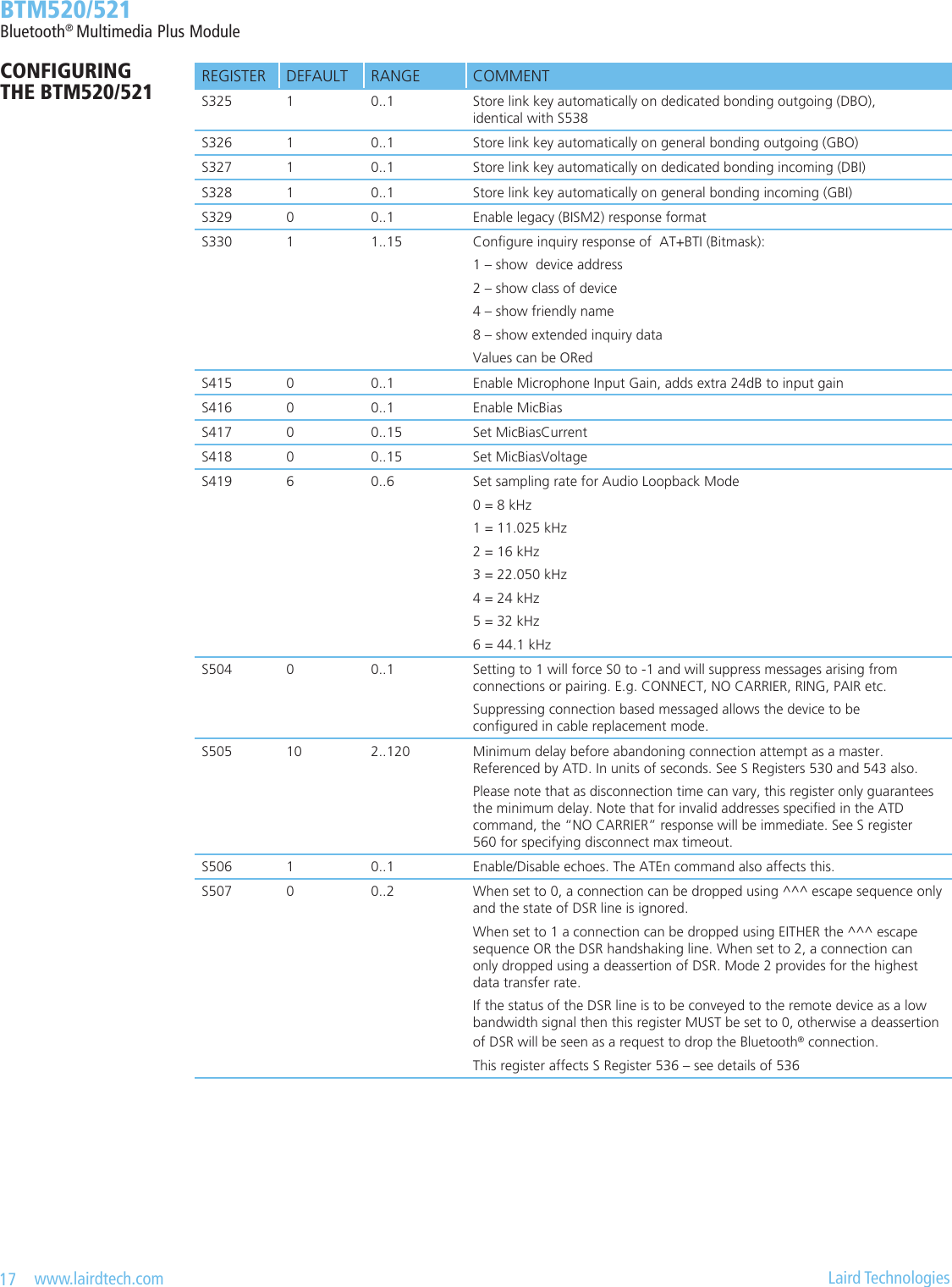
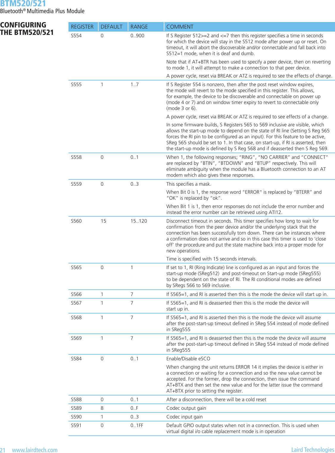
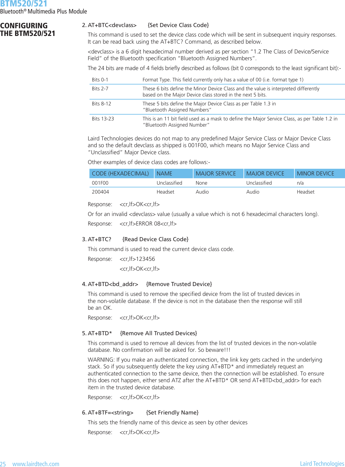
![11 www.lairdtech.com Laird Technologies BTM520/521Bluetooth® Multimedia Plus ModuleCONFIGURING THE BTM520/521INTRODUCTIONThis document describes the protocol used to control and congure the BT-MM+ Bluetooth device. The AT commands described in the document apply to rmware releases from V14.0.9 onwards.The protocol is similar to the industry standard Hayes AT protocol used in telephony modems which is appropriate for cable replacement scenarios, as both types of devices are connection oriented. Just like telephony modems, Laird Technologies’ devices powers up in an unconnected state and will only respond via the serial interface. In this state the device will not even respond to Bluetooth Inquiries. Then, just like controlling a modem, the host can issue AT commands which map to various Bluetooth activities. The command set is extensive enough to allow a host to make connections which are authenticated and/or encrypted or not authenticated and/or encrypted or any combination of these. Commands can be saved, so that on a subsequent power up the device is discoverable or automatically connects. The device has a serial interface which can be congured for baud rates from 1200 up to 921600 (default setting is 9600) and an RF communications end point. The latter has a concept of connected and unconnected modes and the former will have a concept of command and data modes. This leads to the matrix of states shown below.RF UNCONNECTED RF CONNECTEDLocal Command Mode OK OKRemote Command Mode ILLEGAL OKData Mode ILLEGAL OKThe combinations, ‘Data and RF Unconnected Mode’ and ‘Remote Command and RF Unconnected Mode’ do not make sense and will be ignored.Navigation between these states is done using the AT commands which are described in detail in subsequent sections.REFERENCES [1] “AT Command Set” [2] “BlueLab_v4.0_Release_Note.pdf” [3] “Audio/Video Distribution Transport Protocol Specication” Rev.V12, 16/04/2007 [4] “Advanced Audio Distribution Prole Specication” Rev. V12, 16/04/2007 [5] “Audio/Video Remote Control Prole” Revision V14r00, 26/06/2008 [6] “Software Release Note Stereo Headset SDK Q3 2007 RC3.1” CS-117522-RNP1, CSR [7] “Stereo Headset SDK Q3 2007 User Guide” CSR, CS-116451-UGP1, CSR, December2007 [8] “Bluetooth Specication Version 2.1 + EDR [vol3]”, 26 July 2007](https://usermanual.wiki/Ezurio/520B.User-Manual/User-Guide-1170046-Page-11.png)

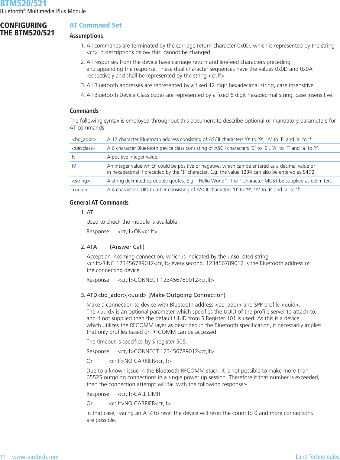
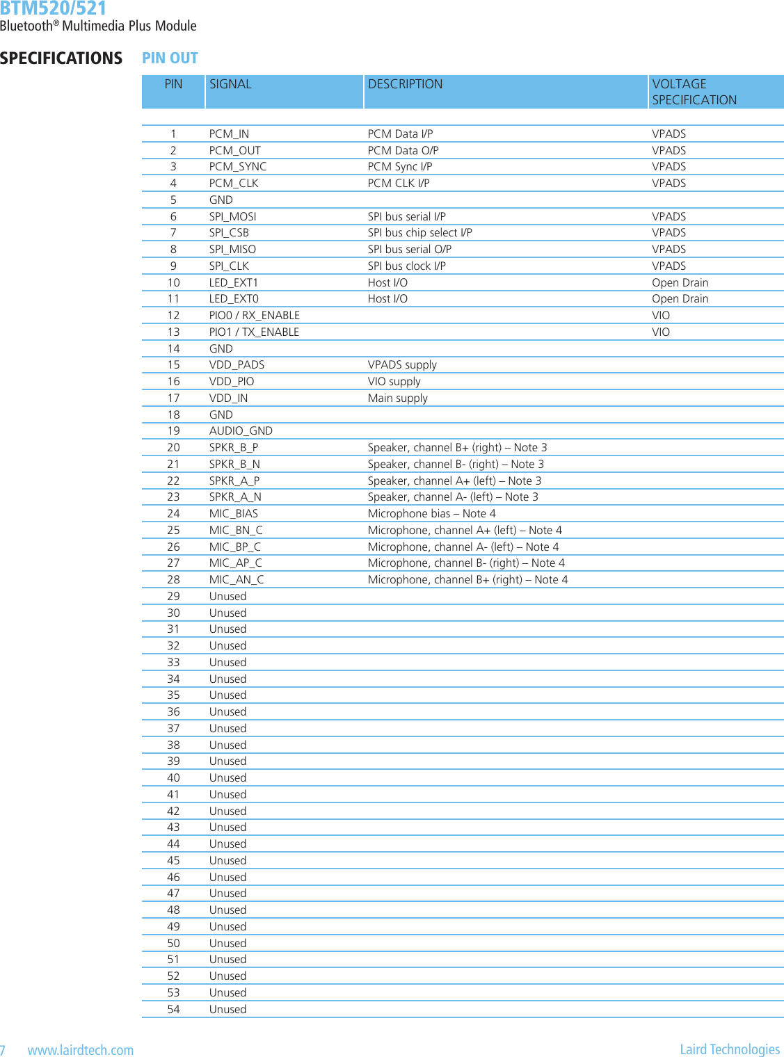
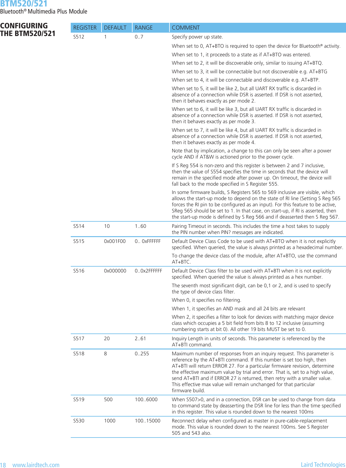
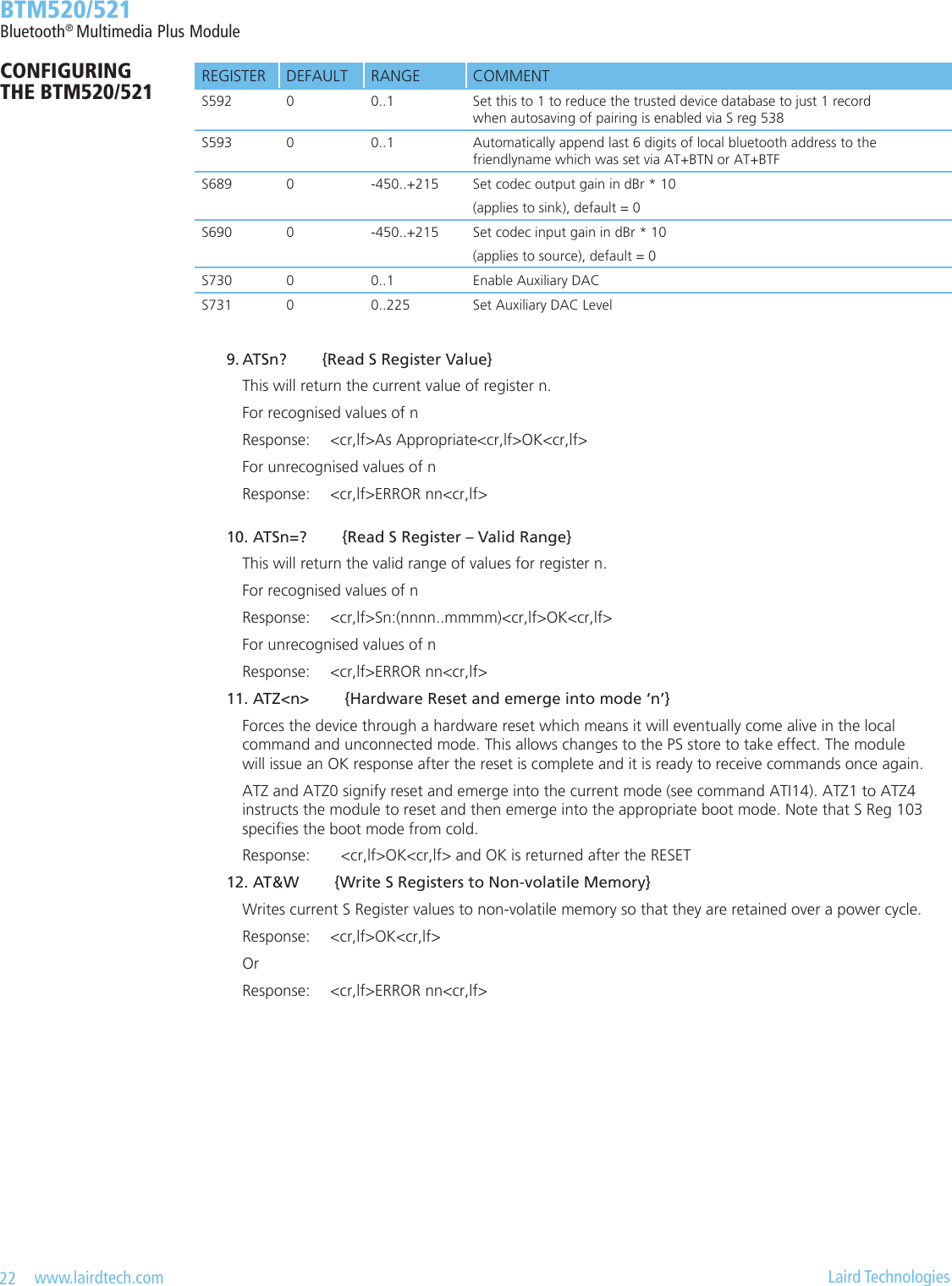
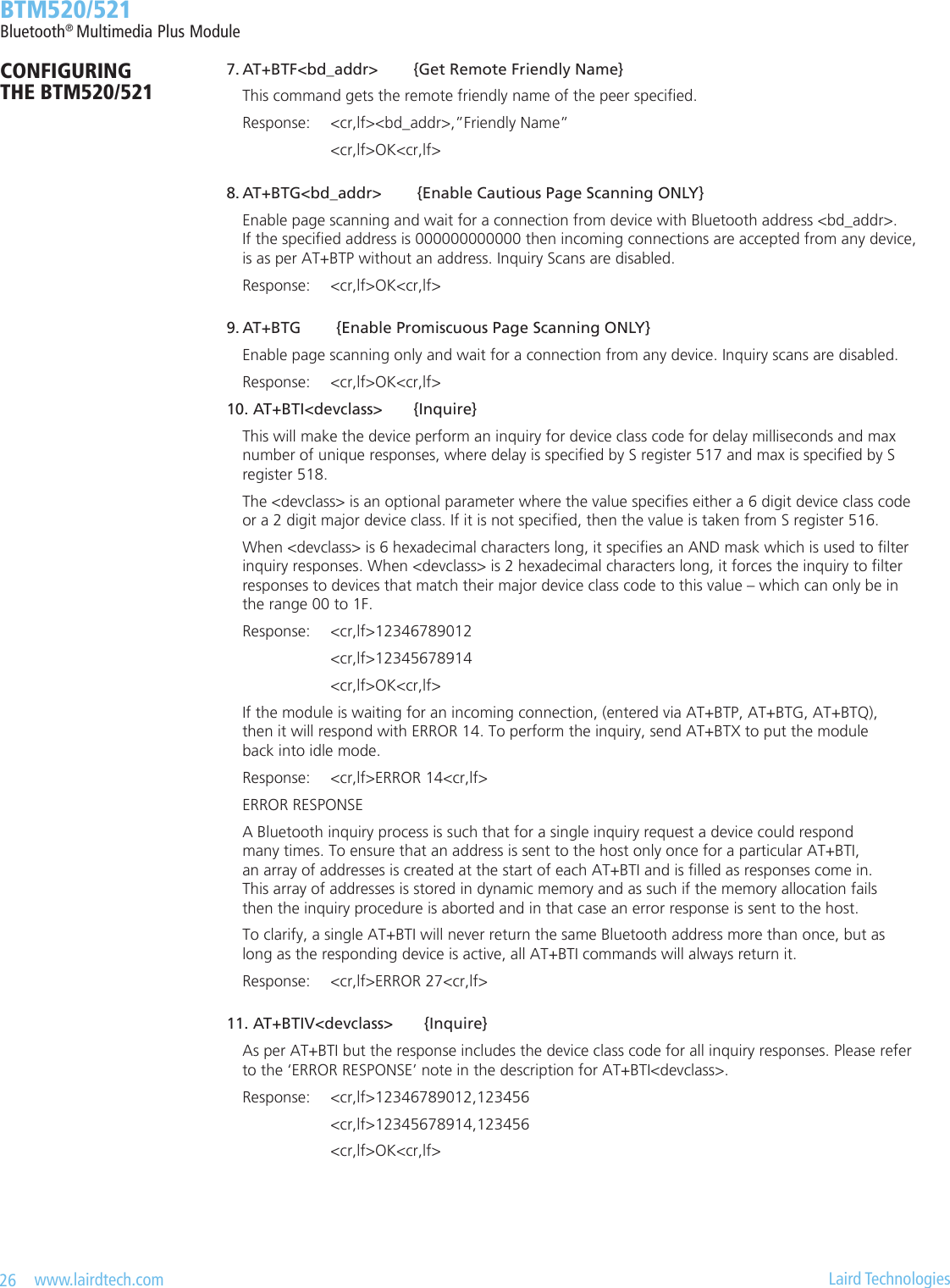
![16 www.lairdtech.com Laird Technologies BTM520/521Bluetooth® Multimedia Plus ModuleCONFIGURING THE BTM520/521 REGISTER DEFAULT RANGE COMMENTS302 0 0..4 Set AVRCP category:0 is Feature disabled (default)1 is Player/Recorder2 is Monitor/Amplier3 is Tuner4 is MenuS303 0 0..0xFFFFFF Set Company ID:IEEE Company ID, 24bit hexadecimal,Required for UNIT INFO Response in AVRCP target mode, default value is 0.S305 1 0..1 Accept UNIT INFO request:0 – reject1 – acceptS306 1 0..1 Accept SUBUNIT INFO request:0 – reject1 – acceptS310 1 0..1 Congure PASS THROUGH (PT) Response:1 = Enable automatic PT-response, response type is read from S311, (default)0 = Host is required to respond to PT-Indication, see ‘AT+AVR’S311 1 w9 r0..7 (Write) Set automatic PT response:This value is queried for automatic PT-Response, see Table 3-10. The written value is mapped internal, that is why the Read-value is different from the written value. The Read-value is actually sent out as responseS312 1 0..15 A2DP sink supported features (Bitmask) :Bit 0 = Headphone (default)Bit 1 = SpeakerBit 2 = RecorderBit 3 = AmplierS313 1 0..15 A2DP source supported features (Bitmask) :Bit 0 = Player (default)Bit 1 = MicrophoneBit 2 = TunerBit 3 = MixerS320 2 1..3 Security Level: see [12], Generic Access Prole - Table 5.7needs subsequent ‘AT&W’ and power cycle to take effectS321 1 0..4 Set IO capability:0 – display only1 – display yes no2 – keyboard only3 – no input no output4 – reject IO-cap requestsS322 0 0..1 Force man-in-the-middle-protection (MITM):0 – disabled1 – enabledS323 0 0..1 Disable legacy (pre-BT2.1) Pairing:0 – legacy pairing enabled1 – legacy pairing disabledS324 90 1..255 Secure Simple Pairing timeout in sThis value must be at least 90 in order to meet the recommendation of BT2.1 specication](https://usermanual.wiki/Ezurio/520B.User-Manual/User-Guide-1170046-Page-16.png)
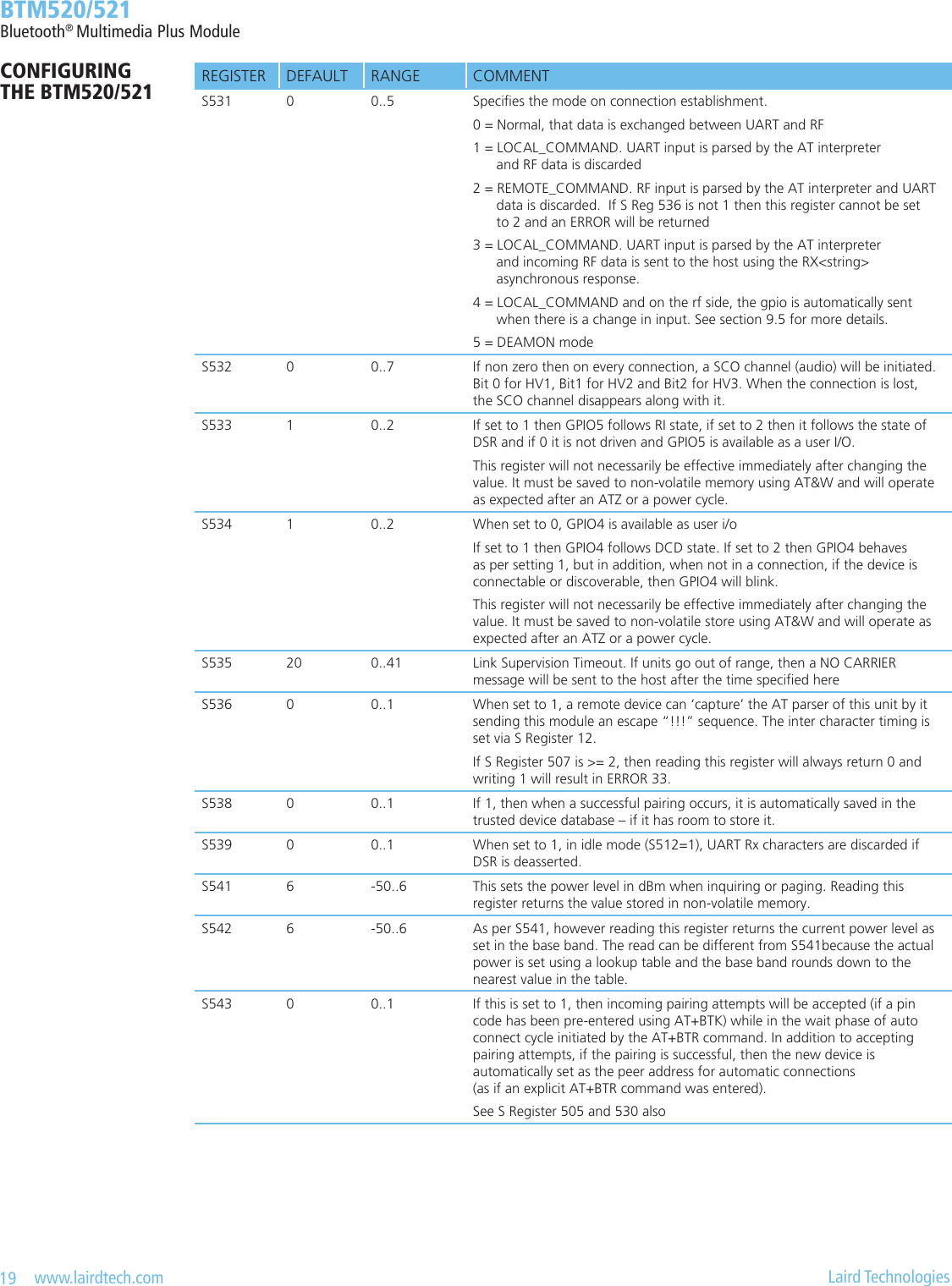
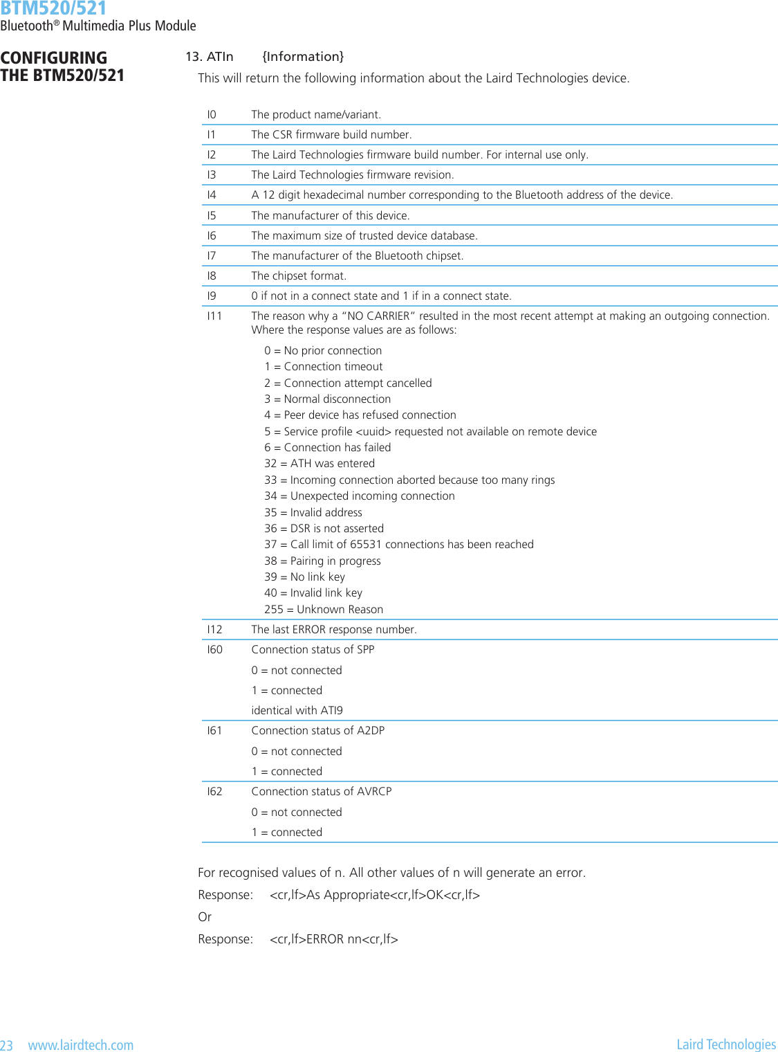
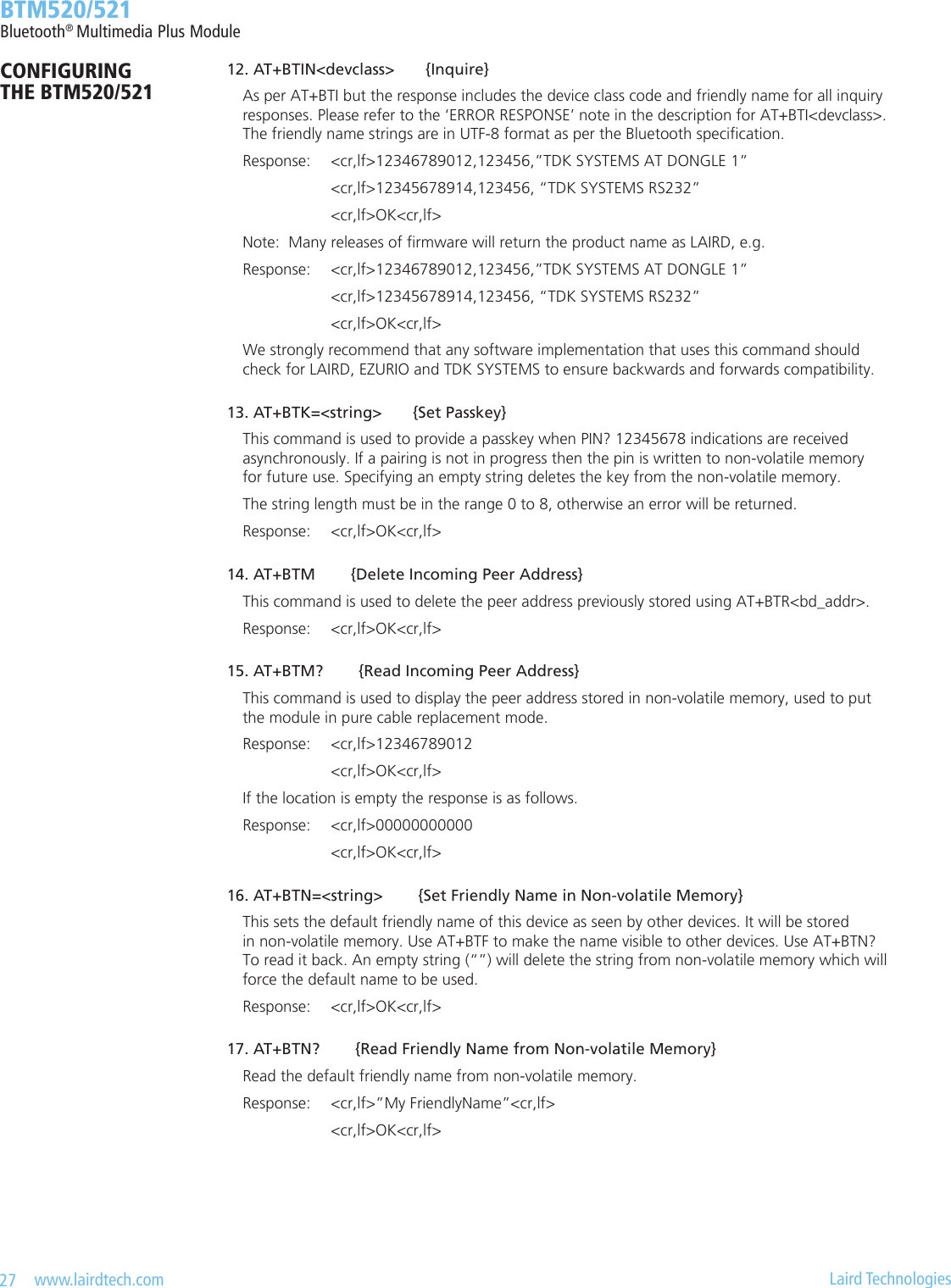
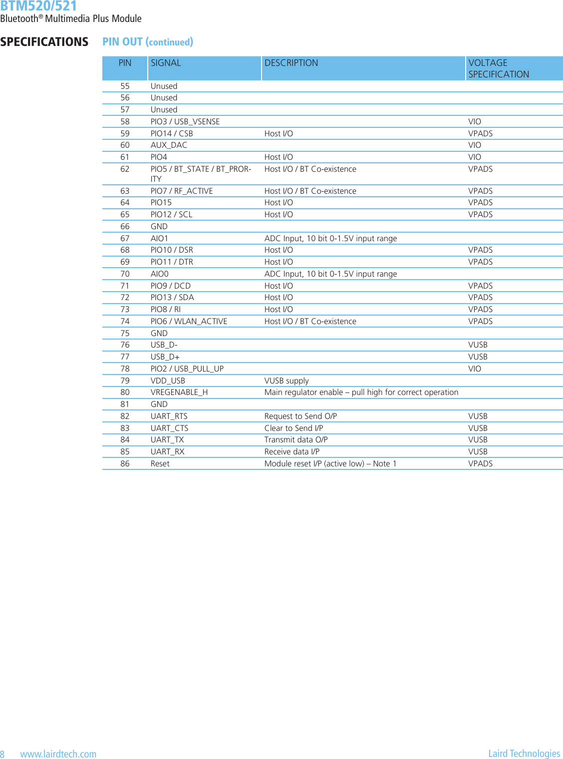
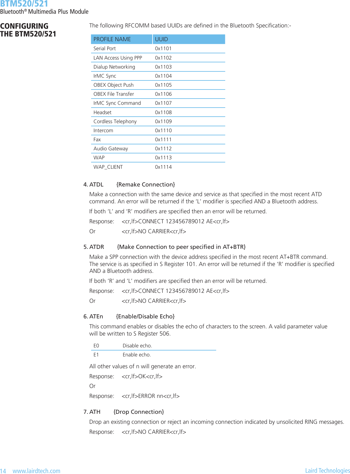
![30 www.lairdtech.com Laird Technologies BTM520/521Bluetooth® Multimedia Plus ModuleCONFIGURING THE BTM520/521Hardware Unit ControlThis section covers S-Registers and AT-Commands that are related to hardware units within the module. 1. Audio Loopback Mode For testing purposes, an audio loopback mode will be introduced. The stereo audio input signal is fed through the Kalimba DSP with running SBC codec, and is directed back to the audio stereo output. Audio Loopback Mode is controlled with the new AT Command “AT+BTL”. 2.CodecGain On BC05-MM, analogue input and output gains can be set to one of 23 steps called “Gain Level”. To each gain level, an overall gain (dBr) is assigned, according to Table 3 3: Gain Table. Gain values can be specied either as gain level or as overall gain by separate S Registers. Please note that a pair of such S-Registers always updates the other corresponding S-Register (e.g. S589 – S689 and S590 – S690). For S689 and S690 the overall gain (dBr) must be entered multiplied by 10. If the input value doesn’t match a gain table entry, the nearest possible value is set. The actually set value can be checked by reading back S689/S690. The value of S689/S690 is printed out multiplied by 10 in order to avoid non integer numbers. The new command class “AT+G…” is introduced in Bism3 which enables incremental and decremental gain settings. The increment/decrement command corresponds to one row up/down in the gain table (Table 3 3). The Gain level registers S589/S689 and S590/S690 are not affected by increment/decrement commands. Instead, the current gain level is cached and can be retrieved by “AT+G(I|O)?”. There are 2 further commands to restore the cached gain level from S589/S590 (“AT+G(I|O)R”) and to save the currently cached gain level to S589/S590 (“AT+G(I|O)S”).Table 3-2: Audio Loopback AT-Commands and S-RegistersTASK AT-COMMAND / SREGISTER COMMENTSet audio loopback mode AT+BTL<Mode> Mode: 0 = off 1 = on, via PCM 2 = on, via SBC encoder/decoderSet sampling rate for Audio Loopback ModeS419 [0..6], default=6 0 = 8 kHz 1 = 11.025 kHz 2 = 16 kHz 3 = 22.050 kHz 4 = 24 kHz 5 = 32 kHz 6 = 44.1 kHz](https://usermanual.wiki/Ezurio/520B.User-Manual/User-Guide-1170046-Page-30.png)
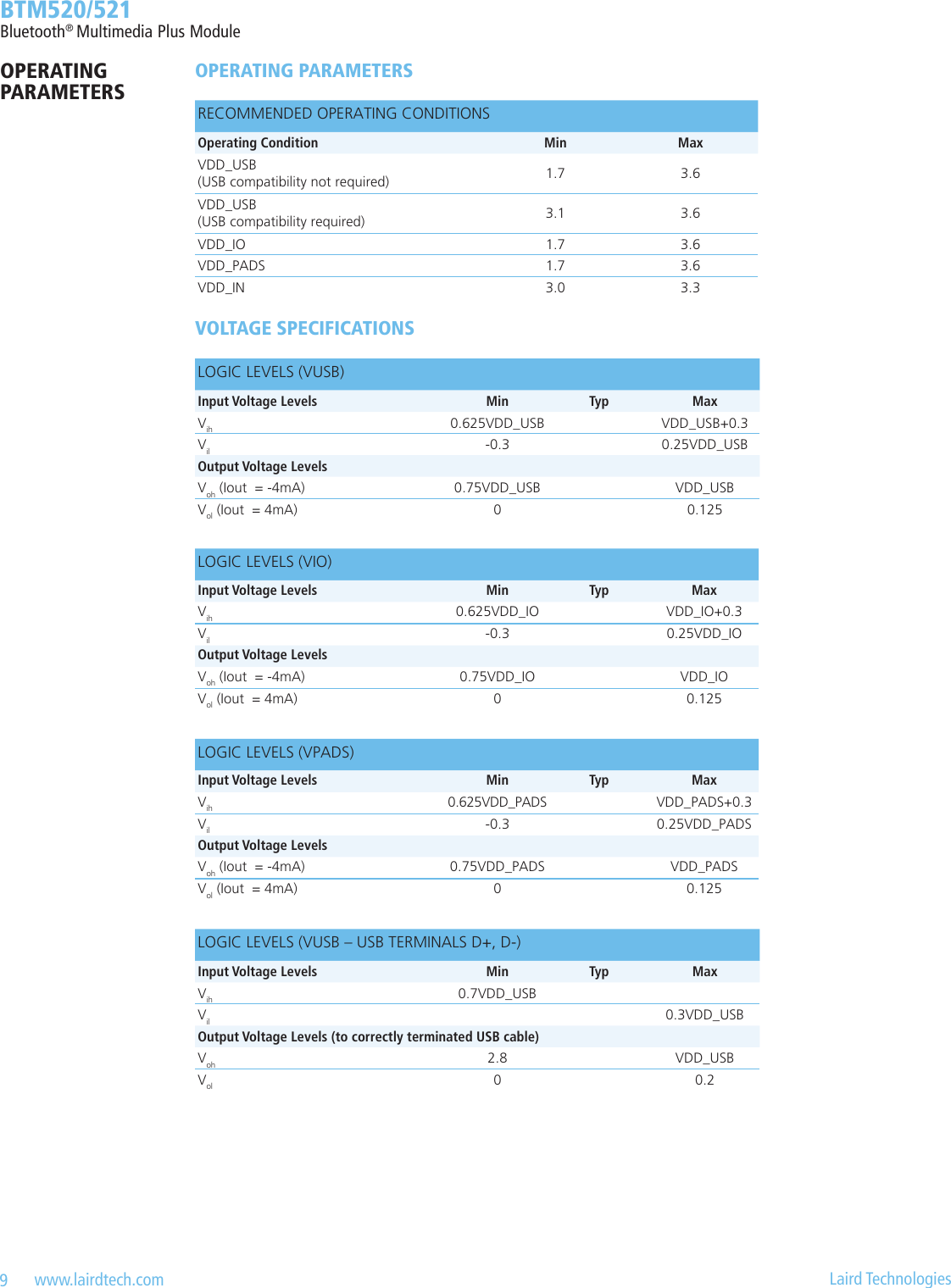
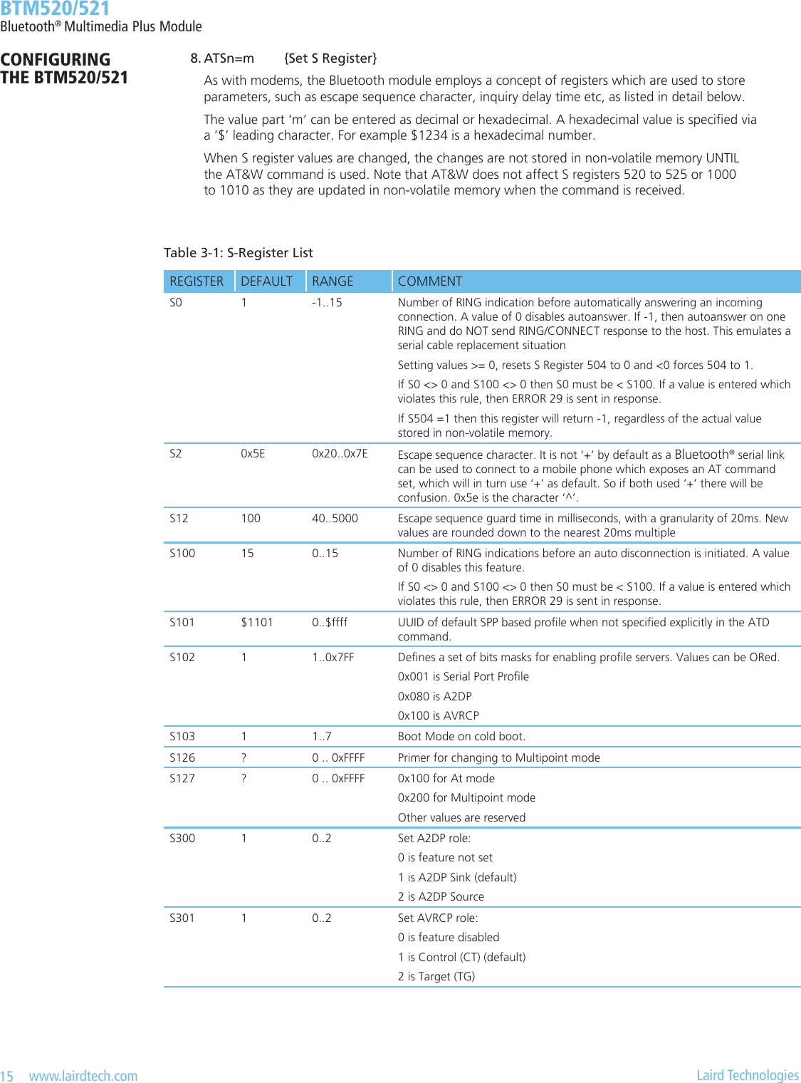
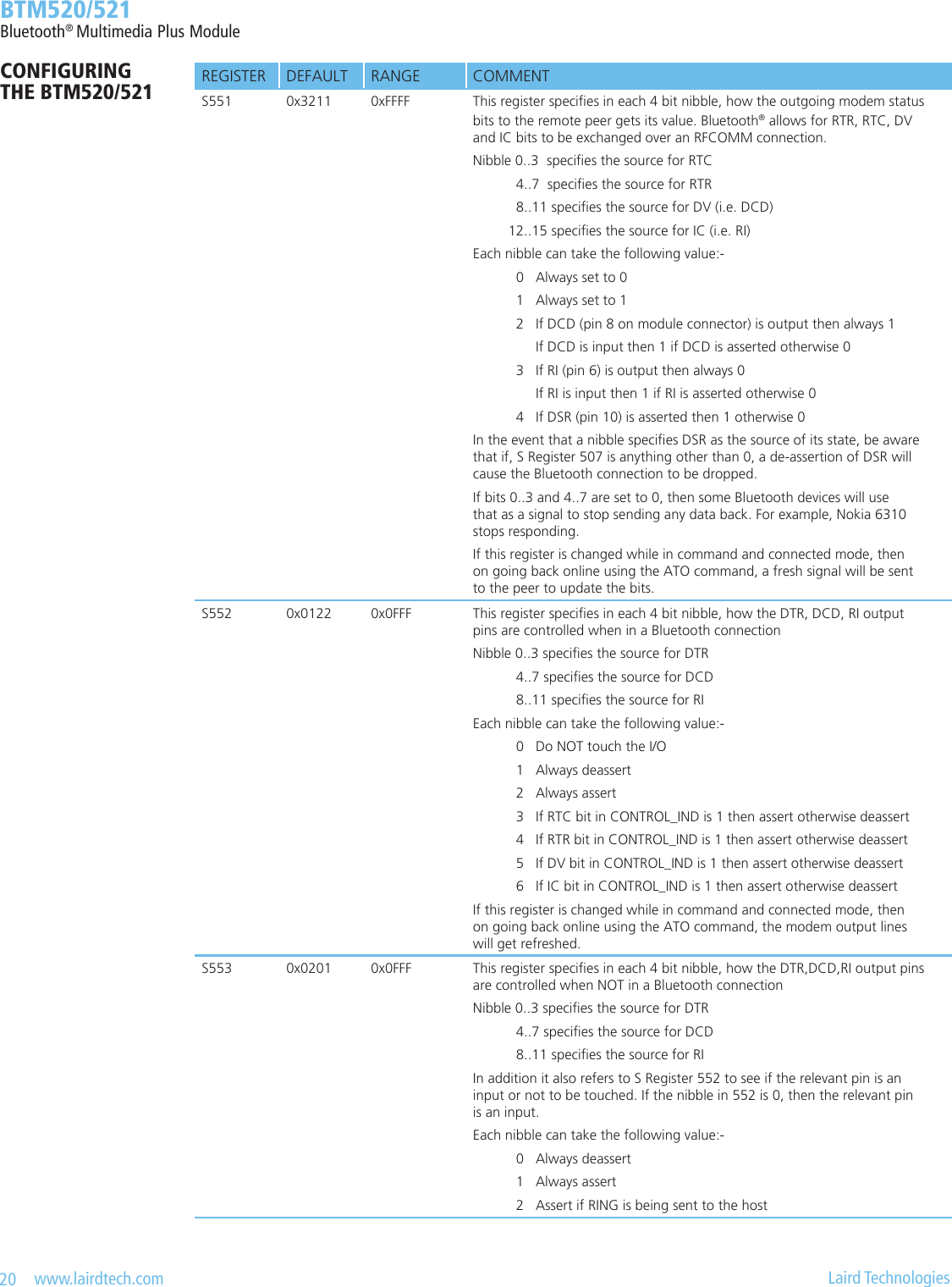
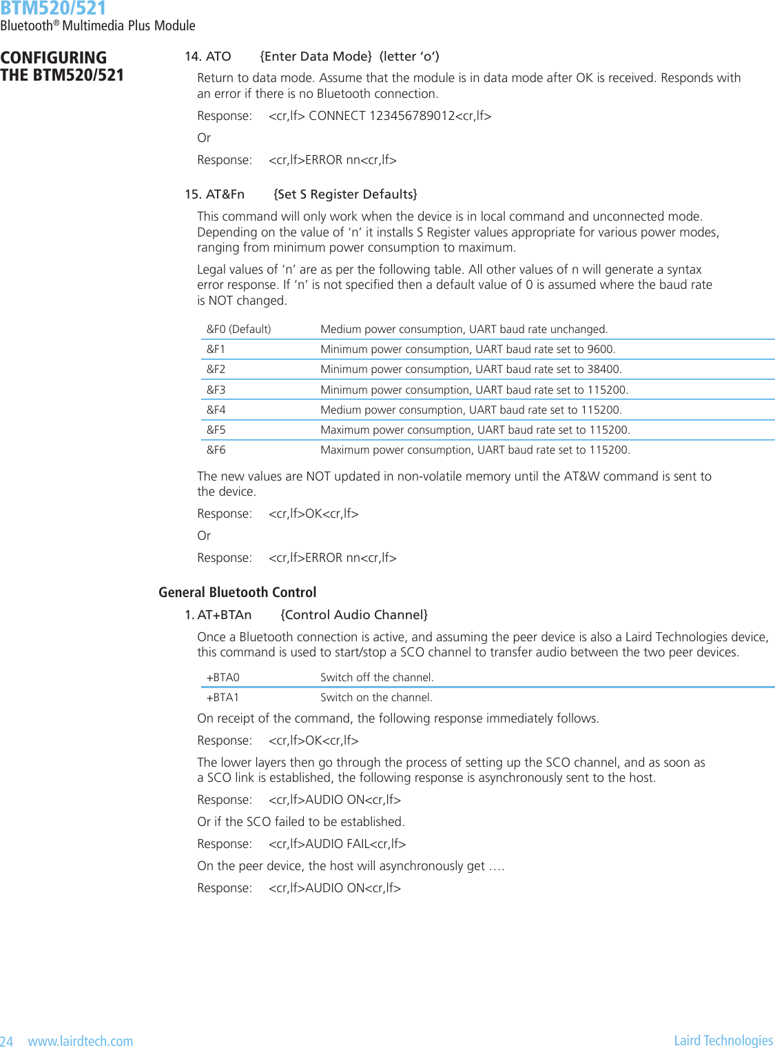
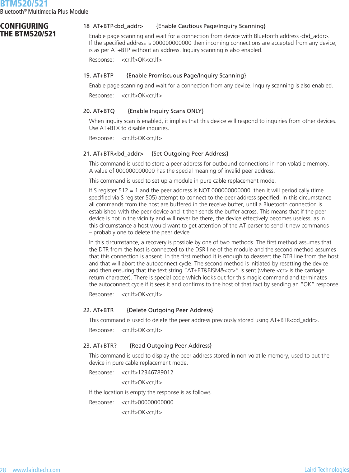
![31 www.lairdtech.com Laird Technologies BTM520/521Bluetooth® Multimedia Plus ModuleCONFIGURING THE BTM520/521Table3-3:GainTableOUTPUT GAIN LEVEL OR INPUT GAIN LEVEL S589 OR S590OVERALL GAIN (DBR) S689 OR S69022 +21.5 21 +18.0 20 +15.5 19 +12.0 18 +9.5 17 +6.0 16 +3.5 15 0 14 -3.0 13 -6.0 12 -9.0 11 -12.0 10 -15.0 9 -18.0 8 -21.0 7 -23.5 6 -27.0 5 -29.5 4 -33.0 3 -35.5 2 -39.0 1 -41.5 0 -45.0 TASK AT-COMMAND / SREGISTER COMMENTSet output gain level S589 [0..22], default=15 See Gain Table; S689 is affected, tooSet output overall gain (dBr) S689 [-450..+215], default=0 See GainTable; value must be entered (and is returned) multiplied by 10; S589 is affected, tooSet input gain level S590 [0..22], default=15 See Gain Table; S690 is affected, tooSet input overall gain (dBr) S690 [-450..+215], default=0 See GainTable; value must be entered (and is returned) multiplied by 10; S590 is affected, tooIncrement current output gain levelAT+GOU Error 57 may appear if maximum gain level reachedDecrement current output gain levelAT+GOD Error 58 may appear if minimum gain level reachedQuery current output gain level AT+GO?Restore current output gain level from S589AT+GORSave current output gain level to S589AT+GOSIncrement current input gain levelAT+GIU Error 57 may appear if maximum gain level reachedDecrement current input gain levelAT+GID Error 58 may appear if minimum gain level reachedQuery current input gain level AT+GI?Restore current input gain level from S590AT+GIRSave current input gain level to S590AT+GISTable3-4:GainSettingsATCommandsandS-Registers](https://usermanual.wiki/Ezurio/520B.User-Manual/User-Guide-1170046-Page-31.png)
![32 www.lairdtech.com Laird Technologies BTM520/521Bluetooth® Multimedia Plus ModuleCONFIGURING THE BTM520/521 3.MicInputGain A microphone preamplier which adds extra 20dB to input gain, is controlled by S-Register 415. 4.MicBias Mic Bias will be enabled with S-Register 416. Mic Bias Current is controlled by S-Register 417. Mic Bias Voltage is controlled by S-Register 418. 5. Auxiliary DAC The auxiliary DAC is enabled with S-Register 730. The DAC output level is set by S-Register 731. 6. LED The BT-MM+ module provides two dedicated output pins for LEDs (LED_EXT0, LED_EXT1). Following modes are supported: LED_OFF, LED_ON, LED_PWM and LED_PULSE. In LED_PWM mode, the parameters “Duty Cycle” an “PWM Period” can be specied via S-Registers. This enables either a to dim the brightness of an LED (PWM Period=0) or to specify blinking with dened on-time in a dened period (PWM Period > blinking visible for the eye) In LED_PULSE mode, the brightness of an LED is modulated. Modulation speed is dened by parameter “Pulse Rate” and maximum brightness is dened by parameter “Duty Cycle”.Bluetooth ProlesThis section covers S-Registers and AT-Commands that are related to the supported Bluetooth Proles on the BT-MM+ module. 1.ProleServerActivation In order to advertise available services to potential client devices, S-Register 102 is used. Supported proles can be activated by setting the appropriate Flag in S-Register 102 (see Table 3 1). After S-Register 102 has been written, all S-Registers must be saved to non-volatile memory (“AT&W”) and subsequently a reset has to be carried out (“ATZ”). 2.A2DP The “Advanced Audio Distribution Prole” is used to transmit high quality audio streams between two Bluetooth devices. An A2DP role must be assigned to a BT-MM+ module, either source or sink. After this has been done, the appropriate service can be advertised. An attempt to advertise A2DP-service without prior set up of a role will result in a (new) response error code 46. An incoming A2DP connection request is accepted automatically if a valid link key for the paging device exists. If no link key is available, Secure Simple Pairing (SSP, BT2.1) or legacy pairing (BT2.0 or earlier) is carried out, depending on the Bluetooth Version of the paging device. After an A2DP connection has been established, the module remains in AT Command mode. S Register 531 is ignored for A2DP connections.Table 3-5: LED S-RegistersTASK AT-COMMAND / SREGISTER COMMENTSet LED_EXT0 mode S335 [0..3], default=0 Mode: 0 = LED_OFF 1 = LED_ON 2 = LED_PWM 3 = LED_PULSESet LED_EXT1 mode S340 [0..3], default=0Set LED_EXT0 Duty Cycle S336 [0..4095], default = 2048 referenced if LED mode = LED_PWM or LED_PULSESet LED_EXT1 Duty Cycle S341 [0..4095], default = 2048Set LED_EXT0 PWM Period S337 [0..15], default = 0 referenced if LED mode = LED_PWMSet LED_EXT1 PWM Period S342 [0..15], default = 0Set LED_EXT0 Pulse Rate S338 [0..15], default = 0 referenced if LED mode = LED_PULSESet LED_EXT1 Pulse Rate S343 [0..15], default = 0](https://usermanual.wiki/Ezurio/520B.User-Manual/User-Guide-1170046-Page-32.png)
![33 www.lairdtech.com Laird Technologies BTM520/521Bluetooth® Multimedia Plus ModuleCONFIGURING THE BTM520/521Table3-6:A2DP-S-RegistersandAT-CommandsTASK AT-COMMAND / SREGISTER COMMENTSet A2DP role S300 [0..2] 0 = feature not set 1 = A2DP Sink (default) 2 = A2DP SourceAdvertise service S102 128 = A2DP, Error 46 if A2DP role has not been set (see S300)Initiate outgoing A2DP connectionAT+APD<bd_addr> Response if accepted: “CONNECT 0123456789012,110D” Response if rejected: “NO CARRIER 110D”close only A2DP connection “AT+APH” or “ATH110D” Response: “NO CARRIER 110D” if connection has existed and S329=0 “NO CARRIER” if connection has not existed and S329=0close all connections ATH* Response: “NO CARRIER <proleUUID>” for each prole that was previously connected (see section 3.7.2)Set gain level S589 [0..22], default = 15 Set codec output gain level (applies to sink)S590 [0..22], default = 15 Set codec input gain level (applies to source)Set overall gain (dBr * 10) S689 [-450..215] Set codec output gain in dBr * 10 (applies to sink), default = 0S690 [-450..215] Set codec input gain in dBr * 10 (applies to source), default = 0Set A2DP sink supported features bit maskS312 [0..15] Bitmask - sink supported features: Bit 0 = Headphone (default) Bit 1 = Speaker Bit 2 = Recorder Bit 3 = AmplierSet A2DP source supported features bit maskS313 [0..15] Bitmask - source supported features: Bit 0 = Player (default) Bit 1 = Microphone Bit 2 = Tuner Bit 3 = Mixer 3.AVRCP The “Audio/Video Remote Control Prole” is used to remotely control audio or video streaming devices. A device must be dened as either control or target. Furthermore, one of four categories (Player/Recorder, Monitor/Amplier, Tuner, Menu) has to be assigned to a device. The AVRCP specication [5] adopts the AV/C Digital Interface Command Set (AV/C command set, dened by the 1394 Trade Association) device model and control message format. In this device model a remote control target consists of one or more subunits. At least the subunit ”PANEL” must exist. Remote control commands are passed to a subunit with the “PASS THROUGH” command. A BT-MM+ Module, congured as target will support one PANEL subunit. 3.1 AVRCP-Control(CT) This section describes AT Commands and S registers used when BT-MM+ is congured as an AVRCP Controller (S301=1).](https://usermanual.wiki/Ezurio/520B.User-Manual/User-Guide-1170046-Page-33.png)
![34 www.lairdtech.com Laird Technologies BTM520/521Bluetooth® Multimedia Plus ModuleCONFIGURING THE BTM520/521 3.1.1 InitiateAVRCPcontrolconnection AT+AVD<bd_addrhex> Initiate AVRCP control connection to Bluetooth address <bd_addrhex>. The module must be congured as AVRCP Control by S register 301 = 1. Furthermore, a category be selected in S register 302. Response: <cr,lf>CONNECT 123456789012,110E<cr,lf> Or: <cr,lf>NO CARRIER 110E<cr,lf> Or: <cr,lf>ERROR 47<cr,lf> Or: <cr,lf>ERROR 48<cr,lf> After an AVRCP connection has been established, the module remains in AT command mode. S Register 531 is ignored for AVRCP connections. 3.1.2 ReleaseAVRCPcontrolconnection AT+AVH Release AVRCP control connection. Response: <cr,lf >NO CARRIER 110E<cr,lf> 3.1.3 SendUNITINFORequest AT+AVU Send a Unit Info request to a connected AVRCP target. Response immediately: <cr,lf>OK<cr,lf> On command completion: <cr,lf>AVUR <n> <unit_idhex> <unit_typehex> <company_idhex><cr,lf> n = statusdec : 0 – success 1 – fail 4 – timeout For unit_type see Table 3 9: AV/C Unit/Subunit Types. 3.1.4 SendSUBUNITINFORequest(incomplete) AT+AVS<pagedec> Send a Subunit Info request to a connected AVRCP target. Response: <cr,lf>OK<cr,lf> (immediately) And: <cr,lf>AVSR <pagedec> <pagedatahex> <cr,lf> (after command completion) <pagedec> : requested page [0..31] <pagedatahex> : 1st word of requested page](https://usermanual.wiki/Ezurio/520B.User-Manual/User-Guide-1170046-Page-34.png)
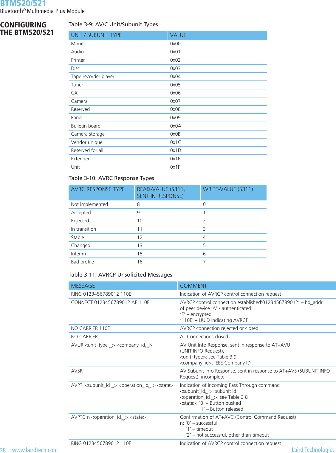
![35 www.lairdtech.com Laird Technologies BTM520/521Bluetooth® Multimedia Plus ModuleCONFIGURING THE BTM520/521 3.1.5 Send remote control command AT+AVC<operation_idhex>,<button_state> Send a remote control command to a connected AVRCP target. Internally, a PASS THROUGH command is created and sent to the PANEL subunit of the AVRCP target. <operation_idhex> is the value for the actual remote control command. Valid values are specied in Table 3 8. Some Operation IDs can be replaced by mnemonics, see Table 3 8. <button_state> represents “Button pushed” (=0) or “Button released” (=1) If <button_state> is not specied, two PASS THROUGH commands, each with button_state=0 and button_state=1 will be created and sent consecutively. The “OK” response is sent immediately on receipt of AT+AVC command. On command completion, an unsolicited message will be sent to the host in the form “AVPTC n <bd_addr> <button_state>”. AVPTC means “AVrcp Pass Through Conrmation”. Parameter n indicates the command status: ‘n’=0: successful, command conrmation received from target ‘n’=1: timeout, target has not sent conrmation within the specied maximum time ‘n’=2: all other unsuccessful outcomes Parameters: <operation_idhex> (mandatory): see Table 3 8 <button_state> (optional) : ‘0’ - Button pushed ‘1’ - Button released Response: <cr,lf>OK<cr,lf> (immediately) And: <cr,lf>AVPTC n <operation_idhex> <button_state><cr,lf> (after command completion) If status n indicates an unsuccessful outcome,<operation_idhex> and <button_state> are omitted. 3.2 AVRCP–Target(TG) This section describes AT Commands and S registers when BT-MM+ is congured as an AVRCP Target (S301=2). In this mode, BT-MM+ supports one subunit PANEL (see [5]). 3.2.1 IncomingAVRCPConnectionRequest An incoming AVRCP connection request is accepted automatically if a valid link key for the paging device exists. If no link key is available, Secure Simple Pairing (SSP, BT2.1) or legacy pairing (BT2.0 or earlier) is carried out, depending on the Bluetooth Version of the paging device. After an AVRCP connection has been established, the module remains in AT command mode. S Register 531 is ignored for AVRCP connections. 3.2.2 UNIT INFO Response It is mandatory to respond to a UNIT INFO command if congured as AVRCP target. Required response parameters are IEEE Company ID and a Unit Type. The IEEE Company ID is a 24 bit integer which can be set via new S register 303. In the current revision of BT-MM+ rmware, subunit “Panel” (=0x09) will be returned always. Values of unit/subunit types are outlined in Table 3 9. 3.2.3 SUBUNITINFOResponse It is mandatory to respond to a SUBUNIT INFO command if congured as AVRCP target. Required response parameters are Subunit type and MaxSubUnitId. Subunit type will always be returned as 0x09 (Panel). MaxSubUnitId will always be returned as 0x00 (only one subunit exists, which is panel)](https://usermanual.wiki/Ezurio/520B.User-Manual/User-Guide-1170046-Page-35.png)
![36 www.lairdtech.com Laird Technologies BTM520/521Bluetooth® Multimedia Plus ModuleCONFIGURING THE BTM520/521 3.2.4 PASSTHROUGHIndication An incoming PASS THROUGH command will be indicated by an unsolicited message AVPTI <subunit_idhex> <operation_idhex> <button_state> For subunit_idhex see Table 3 9. For operation_idhex see Table 3 8. <button_state>: ‘0’ is Button pushed ‘1’ is Button released 3.2.5 PASSTHROUGHResponse AT+AVR<avrc_response_typehex> If S register 310 = 0, a Pass Through (PT) response is required from the host. The response is sent with: AT+AVR<avrc_response_typedec> Parameter: <avrc_response_typedec>: see Table 3 10, write-value. If S register 310 == 1, a Pass Through response is sent automatically with an <avrc_response_type> congured by S register 311. In this case, the host is not required to respond.Table3-7:AVRCP-S-RegistersandAT-CommandsTASK AT-COMMAND / SREGISTER COMMENTSet AVRCP role S301 [0..2] 0 = disabled 1 = Control “CT” (default) 2 = Target “TG”Set AVRCP category S302 [0..4] 0 = Feature disabled (default) 1 = Player/Recorder 2 = Monitor/Amplier 3 = Tuner 4 = MenuSet Company Id S303 [0..0xFFFFFF] IEEE Company ID, 24bit hexadecimal,Required for UNIT INFO Response in AVRCP target mode, default value is 0.Enable Unit Info Response S305 [0..1] default = 1Enable Subunit Info Response S306 [0..1] default = 1Congure PASS THROUGH (PT) ResponseS310 [0..1] 1 = Enable automatic PT-response, response type is read from S311, (default) 0 = Host is required to respond to PT-Indication, see ‘AT+PTR’Set automatic response typeS311 [0.. 7] This value is queried for automatic PT-Response, see Table 3-10 Default value is “accepted” 1w/ 9rAdvertise service S102 256 = AVRCP, Error 47 if AVRCP role has not been set (see S301); Error 48 if S301== 2 and Category has not been set (see S302)Initiate outgoing AVRCP control connectionAT+AVD<bd_addr> Response if accepted: “CONNECT 0123456789012,110E” Response if rejected: “NO CARRIER 110E”Close only AVRCP con-nection“AT+AVH“ or “ATH110E” Response: “NO CARRIER 110E” if connection has existed and S329=0 “NO CARRIER” if connection has not existed and S329=0Close all connections ATH* Response: “NO CARRIER <proleUUID>” for each prole that was previously connected (see Miscellaneous section 2)Send a Unit Info request AT+AVUSend a Subunit Info requestAT+AVS (incomplete!)Send remote control com-mandAT+AVC<operation_idhex>,<state><operation_id>: see Table 3 8, mnemonics possible instead of hexval <state> (optional): ‘0’ Button pushed ‘1’ Button released Response on command completion: “AVPTC n <operation_idhex> <state>”Respond to incoming Pass Through commandAT+AVR<avrc_response_typehex> <avrc_response_typehex>: see Table 3 10 If S 310 == 1, response from host is not required.](https://usermanual.wiki/Ezurio/520B.User-Manual/User-Guide-1170046-Page-36.png)