Ezurio TDK-BTISM Bluetooth Intelligent Serial Module User Manual AT Command Set
Ezurio Ltd Bluetooth Intelligent Serial Module AT Command Set
UserManual.wiki
>
Ezurio
>
TDK-BTISM User Manual
>
AT Command Set
Contents
1.
Users Manual
2.
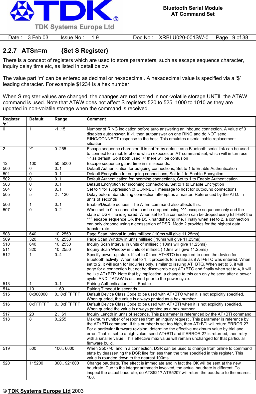
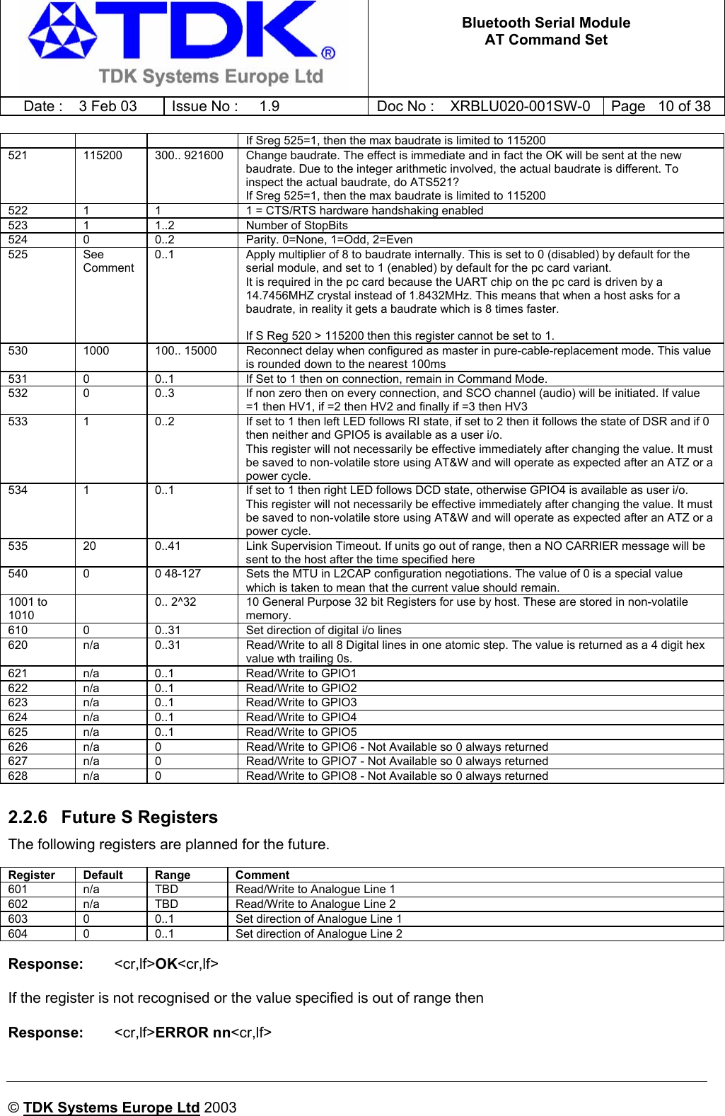
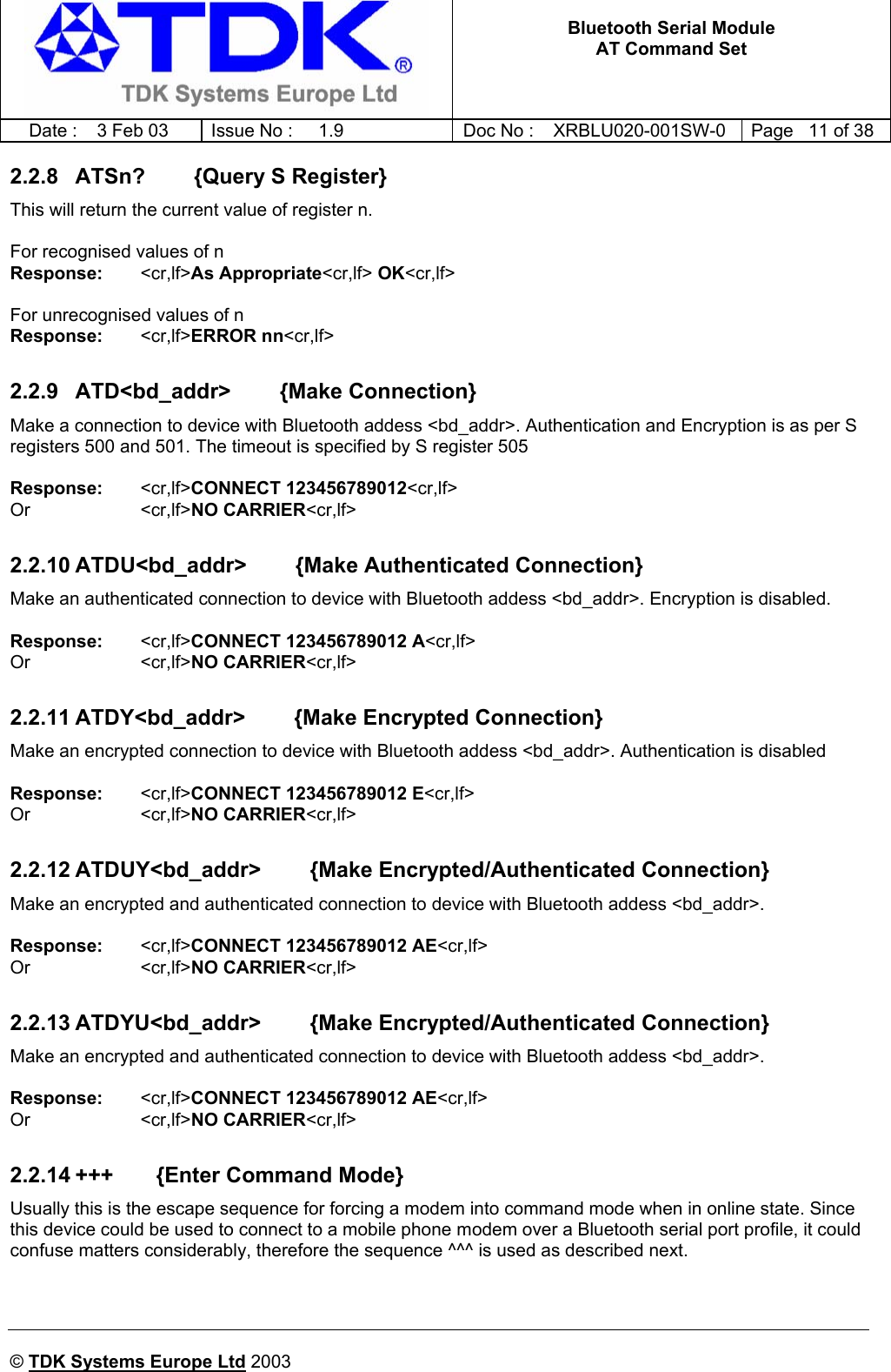
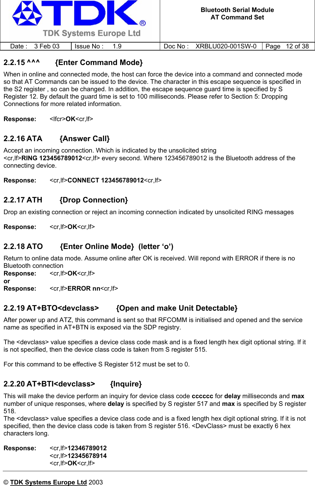
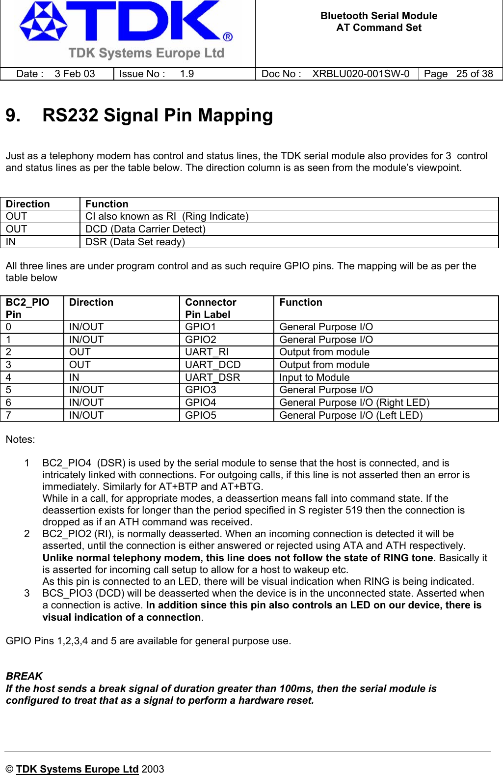
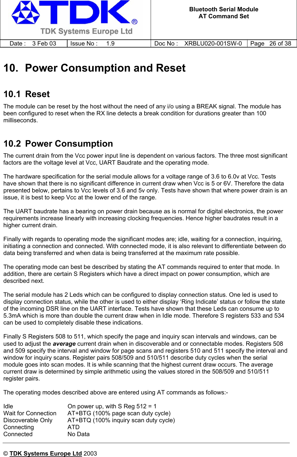
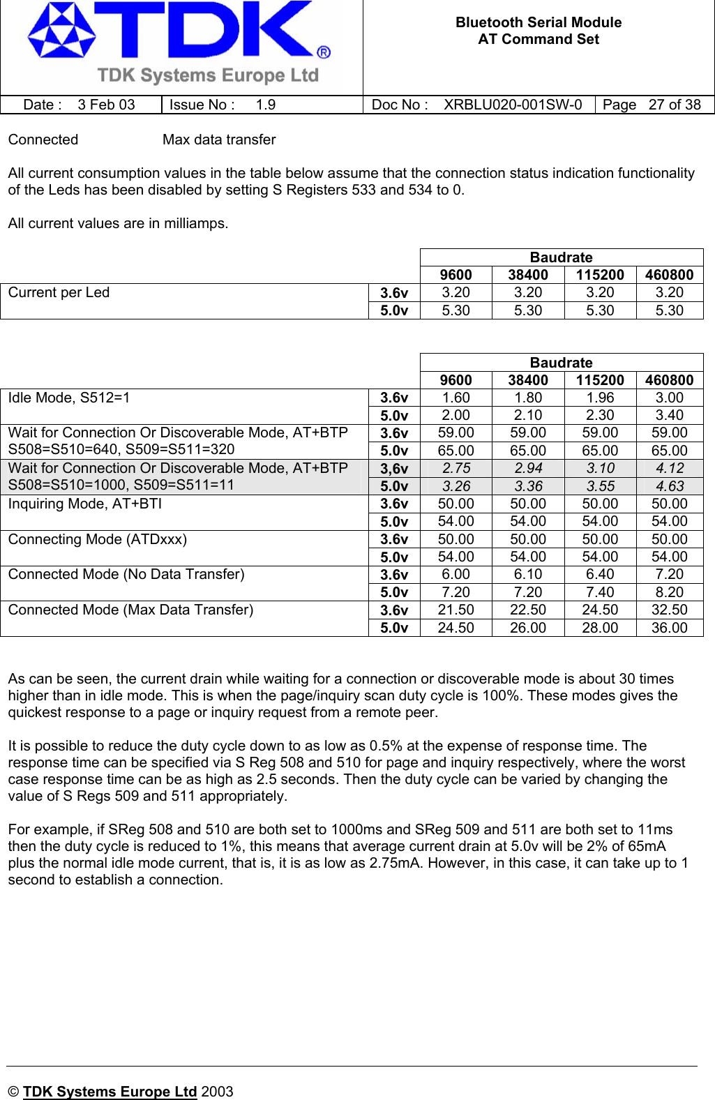
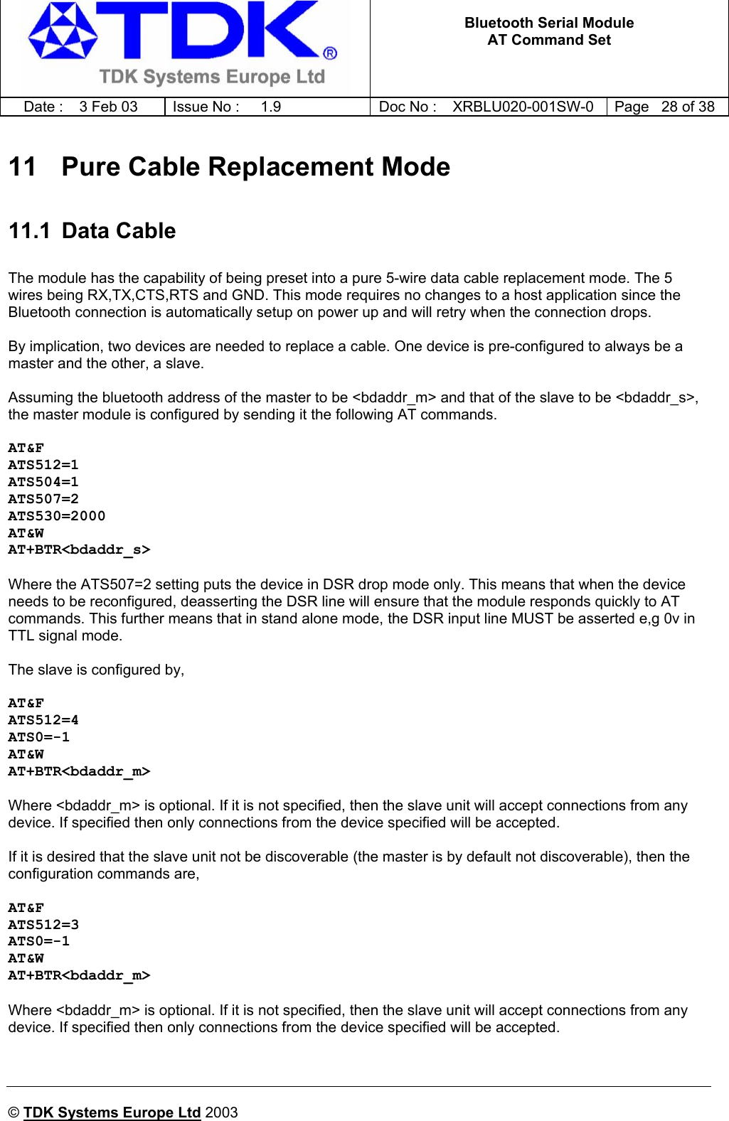
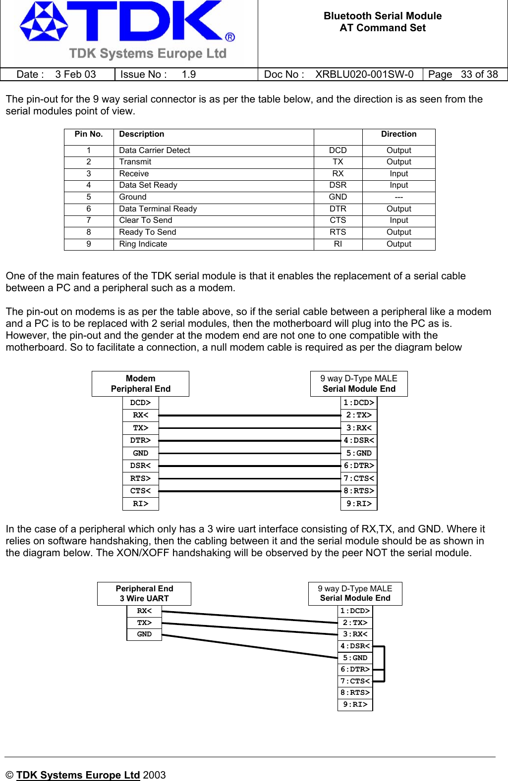
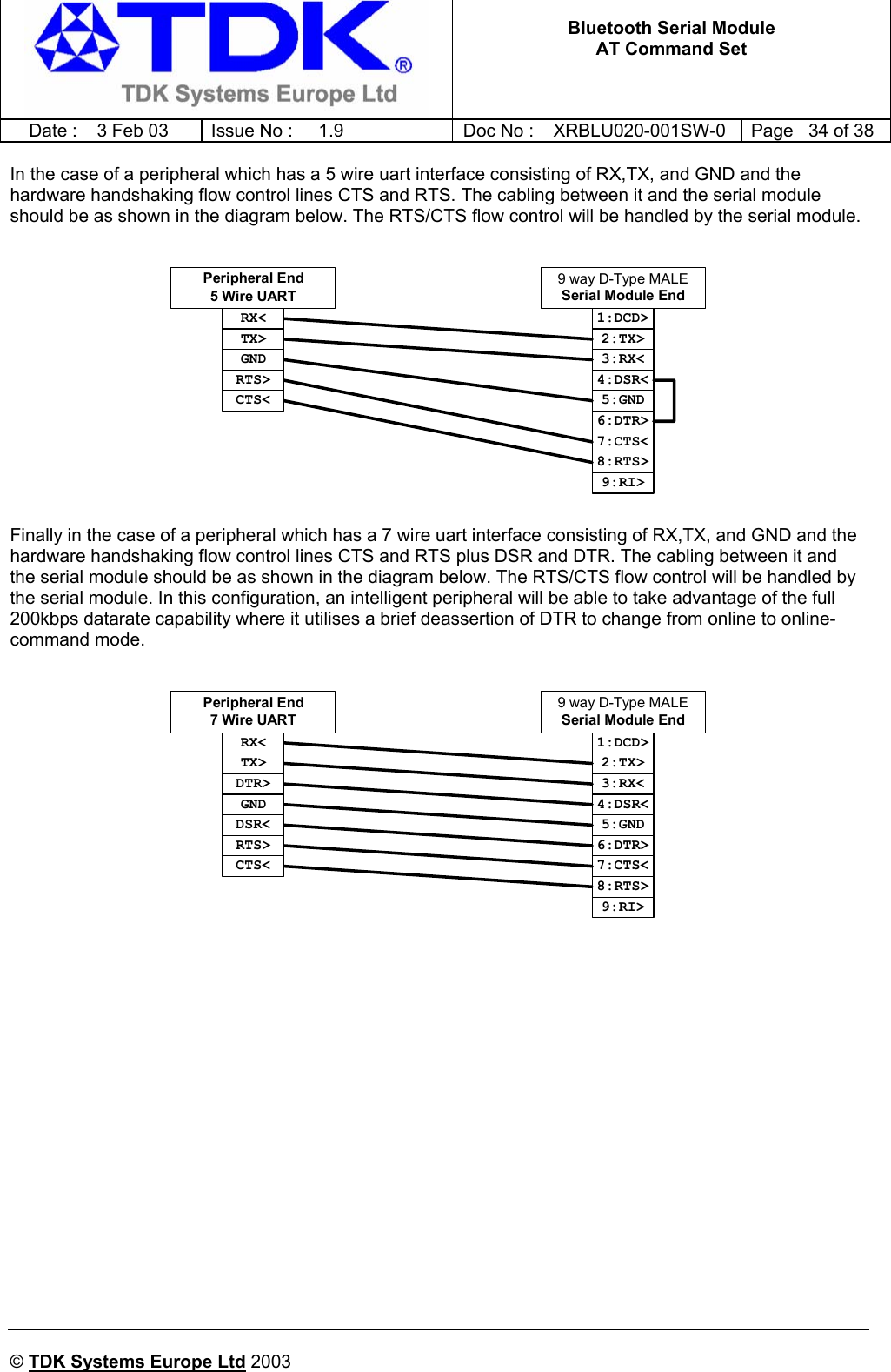
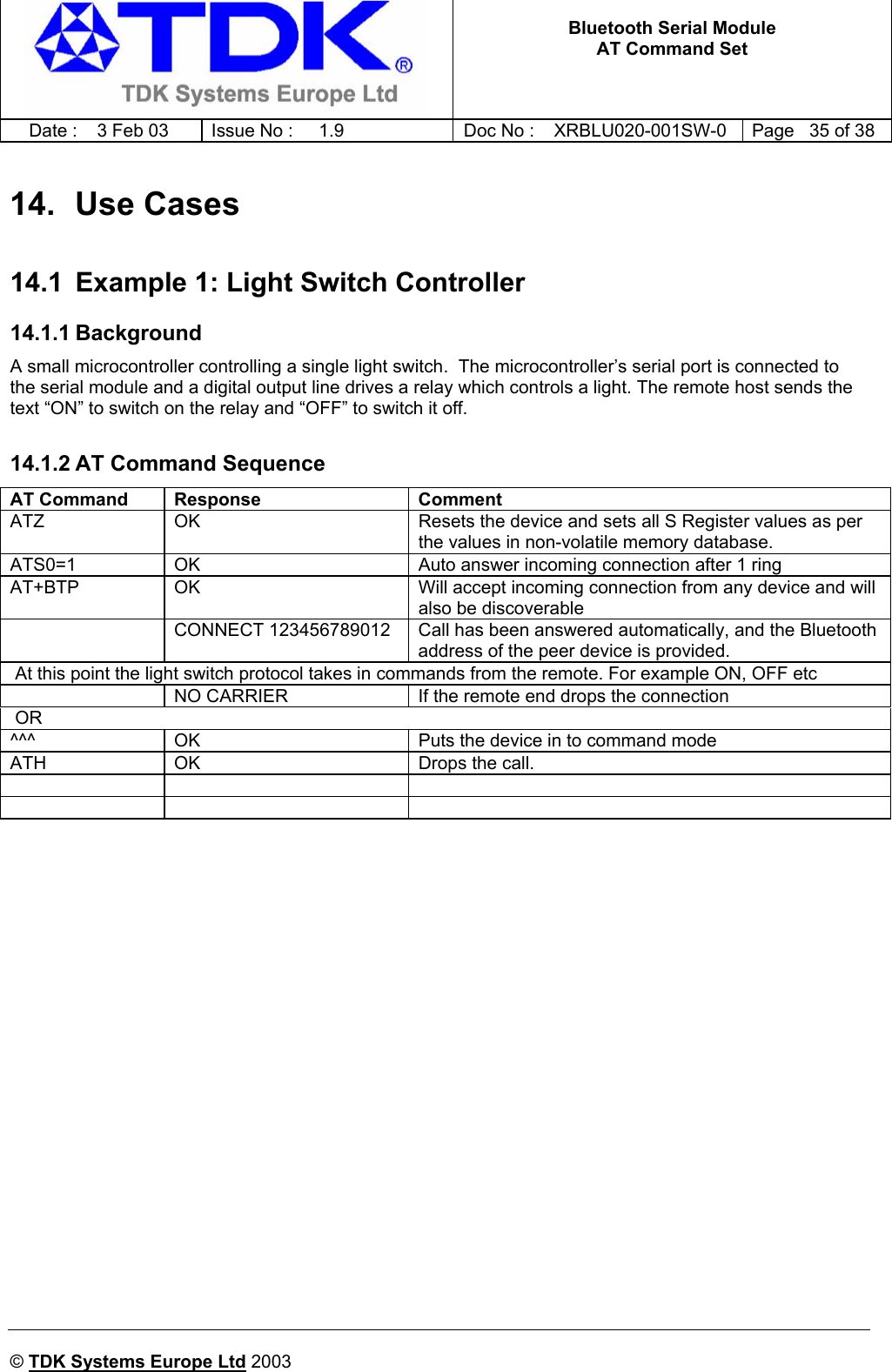
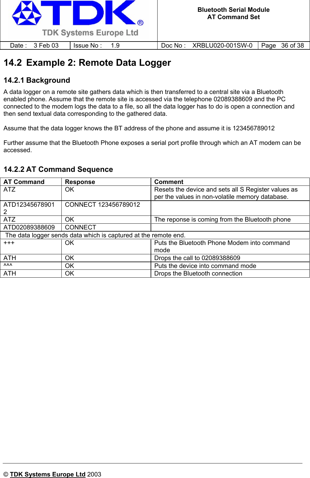
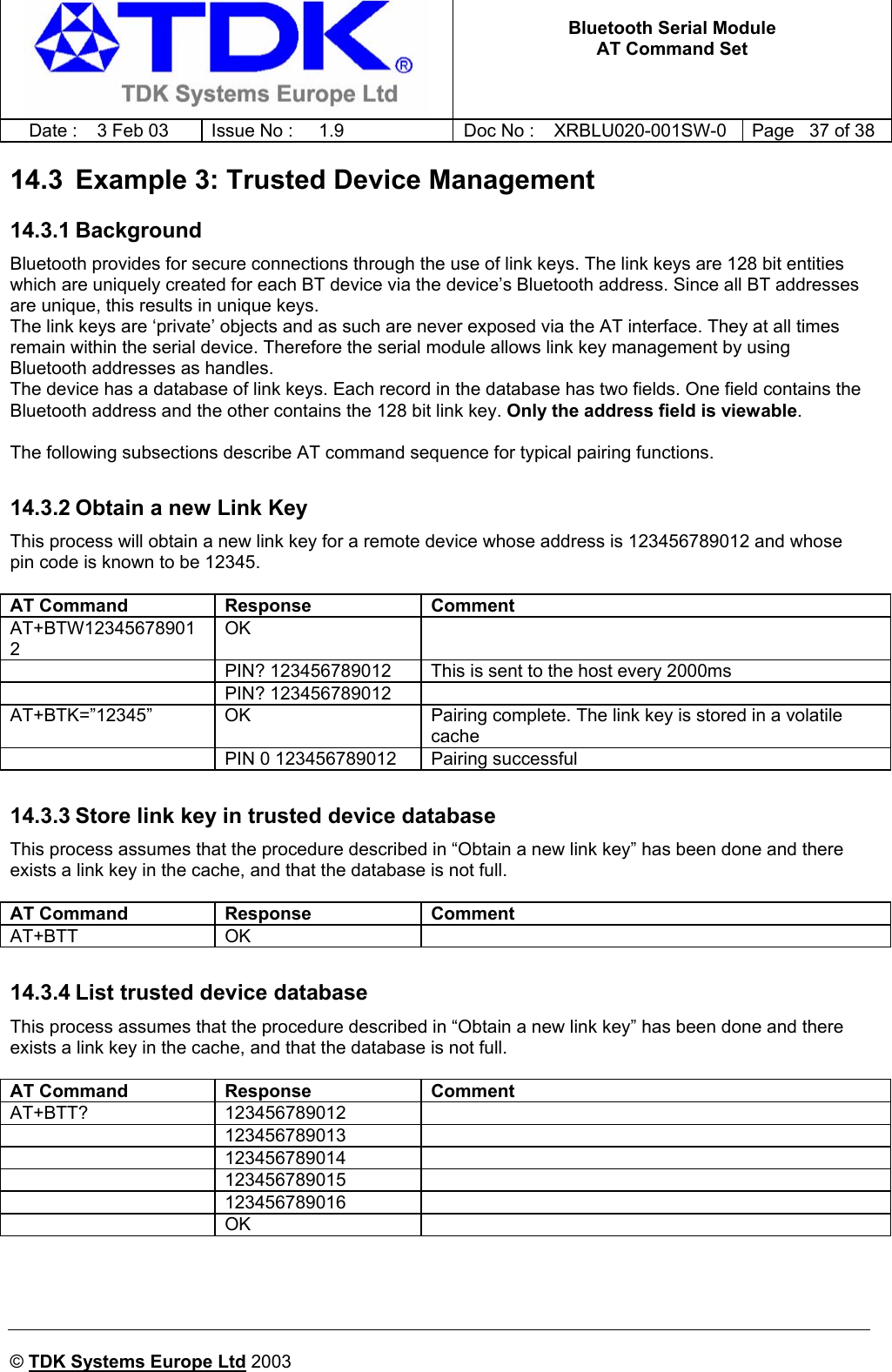
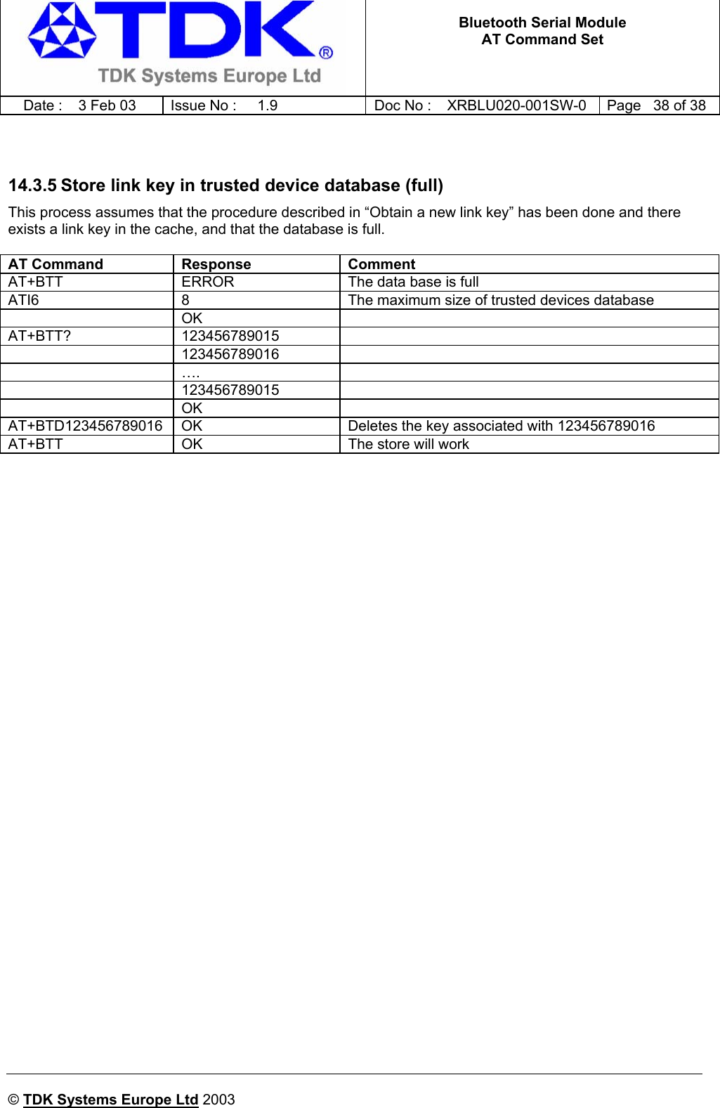
AT Command Set
AT Command Set
Navigation menu
Upload a User Manual
Namespaces
Wiki Guide
HTML
PDF
Info
Views
User Manual
Discussion / Help
Navigation