Ezurio Z100S1XFX 2.4 GHz Direct Sequence Spread Spectrum transceiver module User Manual ZB2430 User s Manual 2 0
AeroComm Corporation 2.4 GHz Direct Sequence Spread Spectrum transceiver module ZB2430 User s Manual 2 0
Ezurio >
Contents
- 1. User Manual
- 2. Product brochure
User Manual


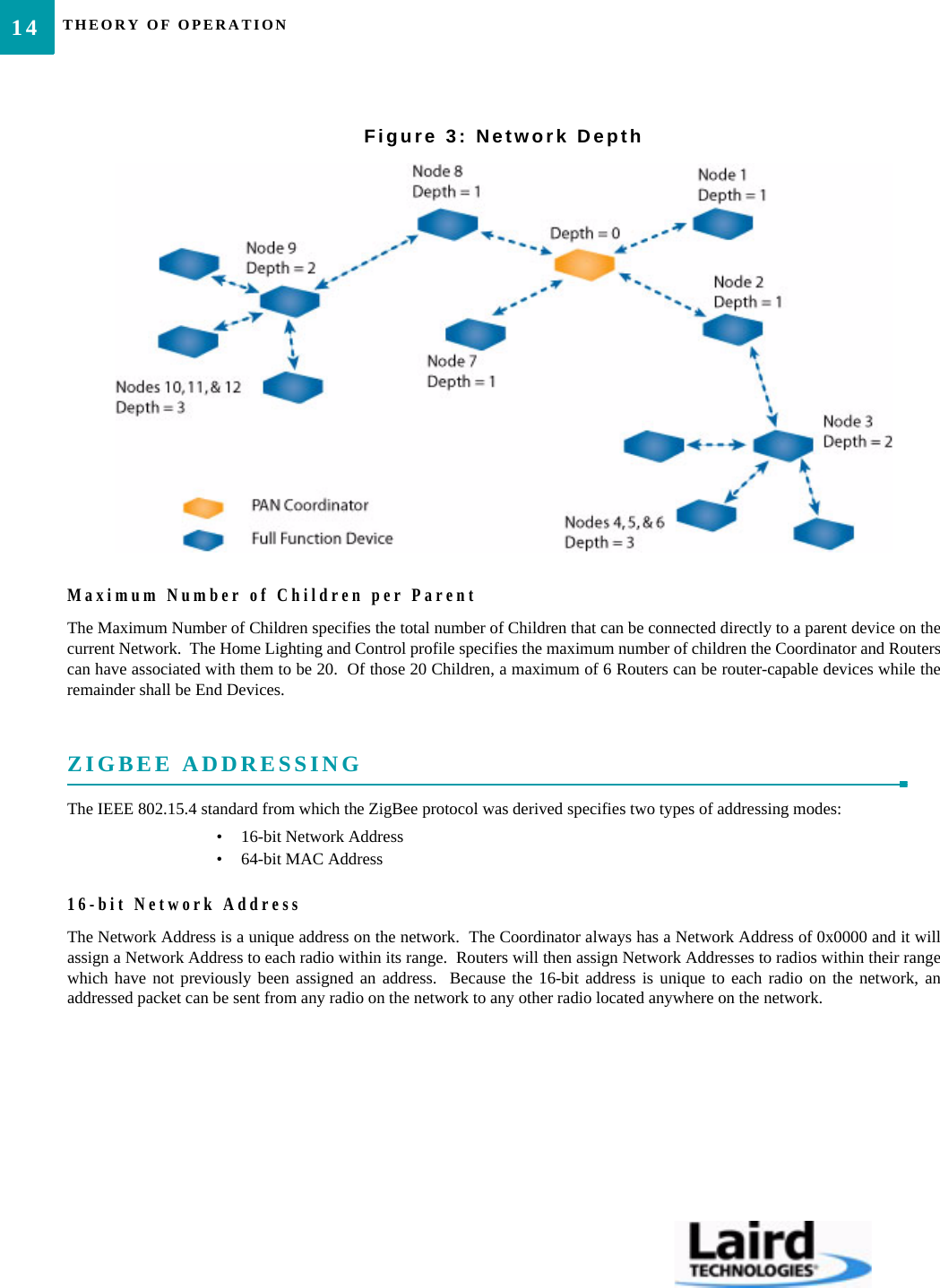
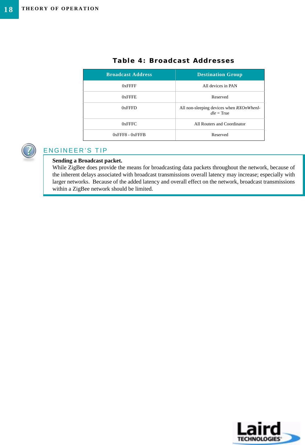
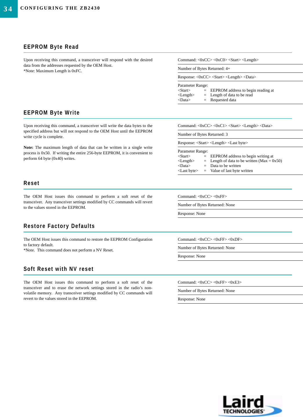
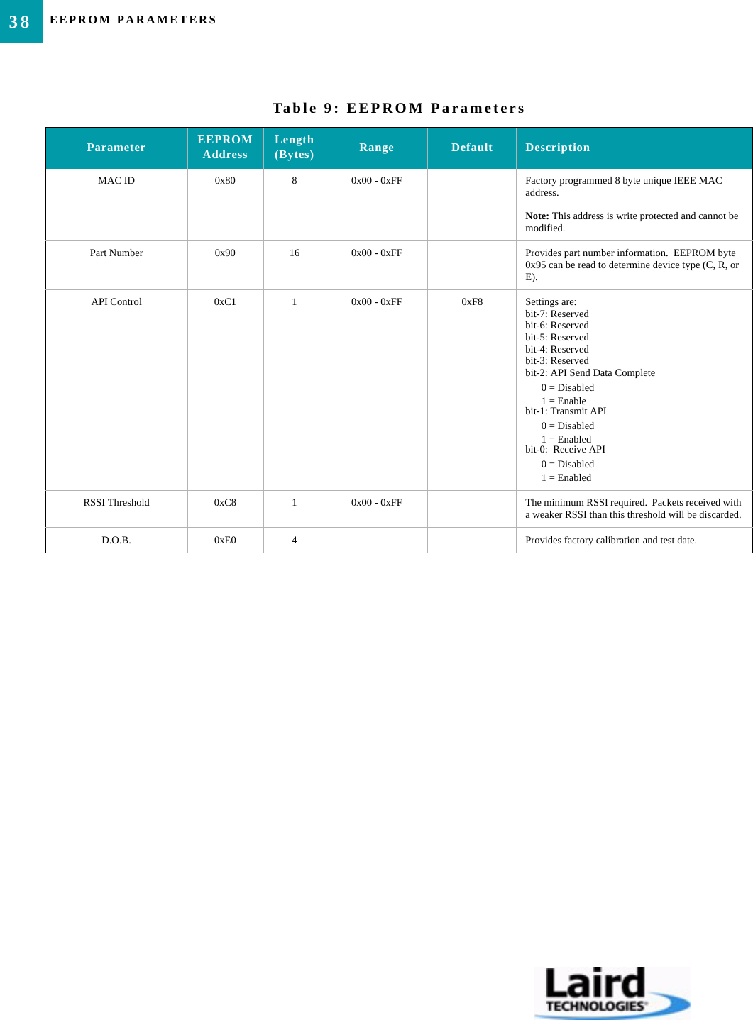
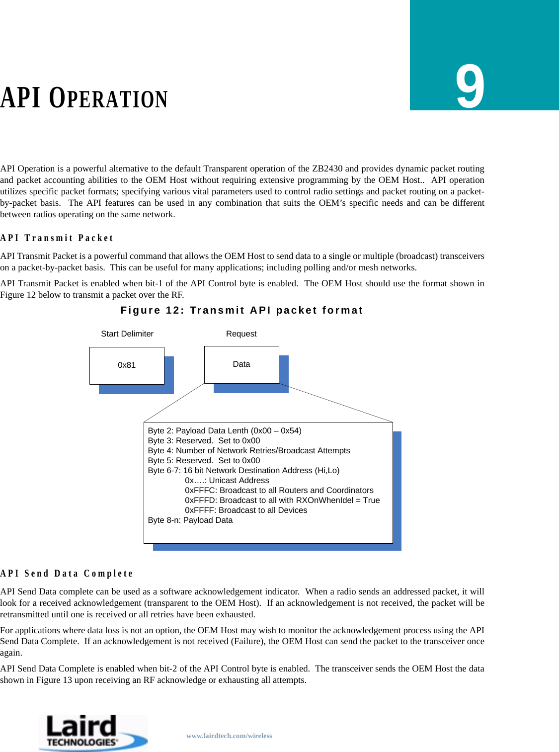
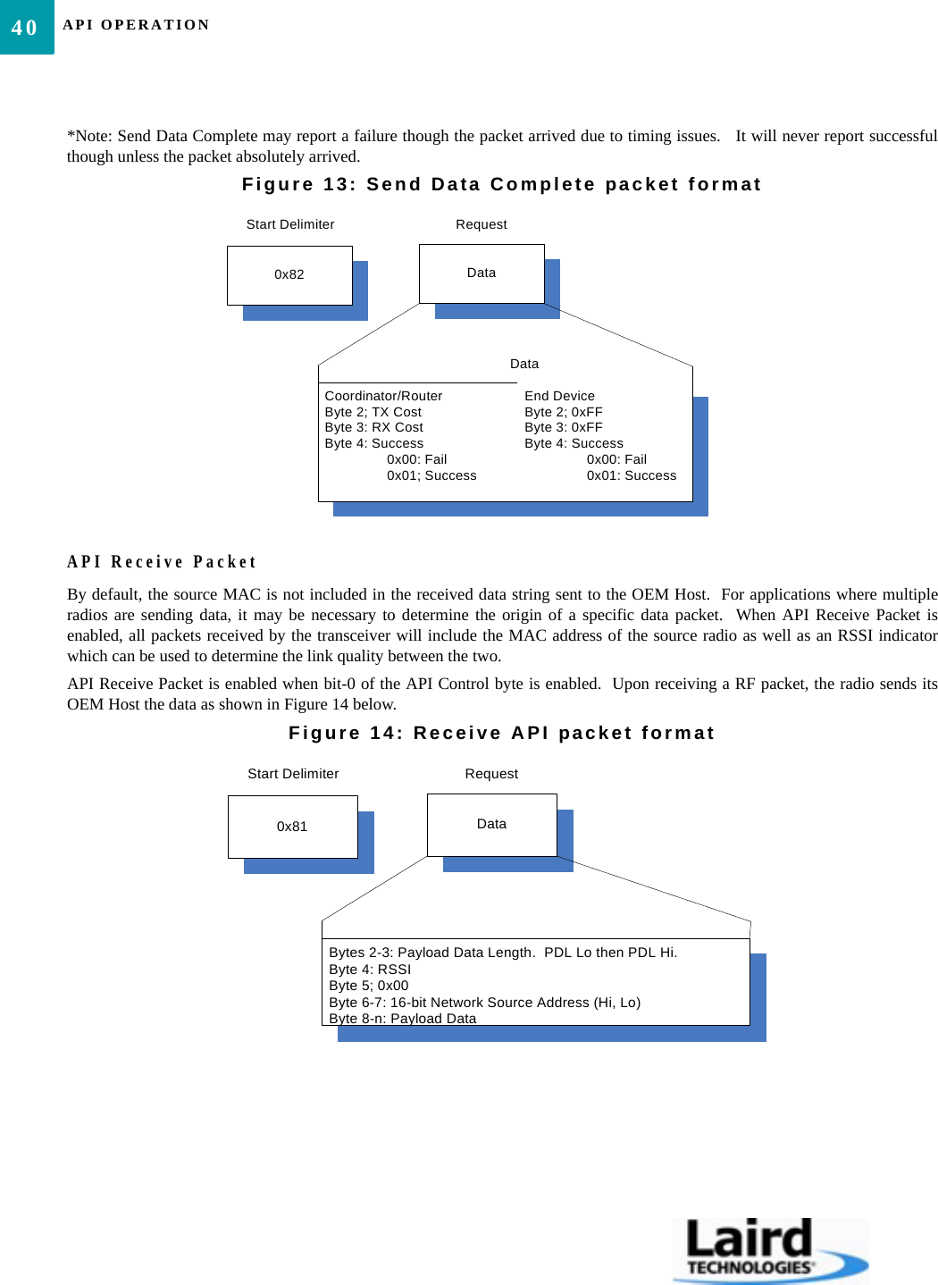
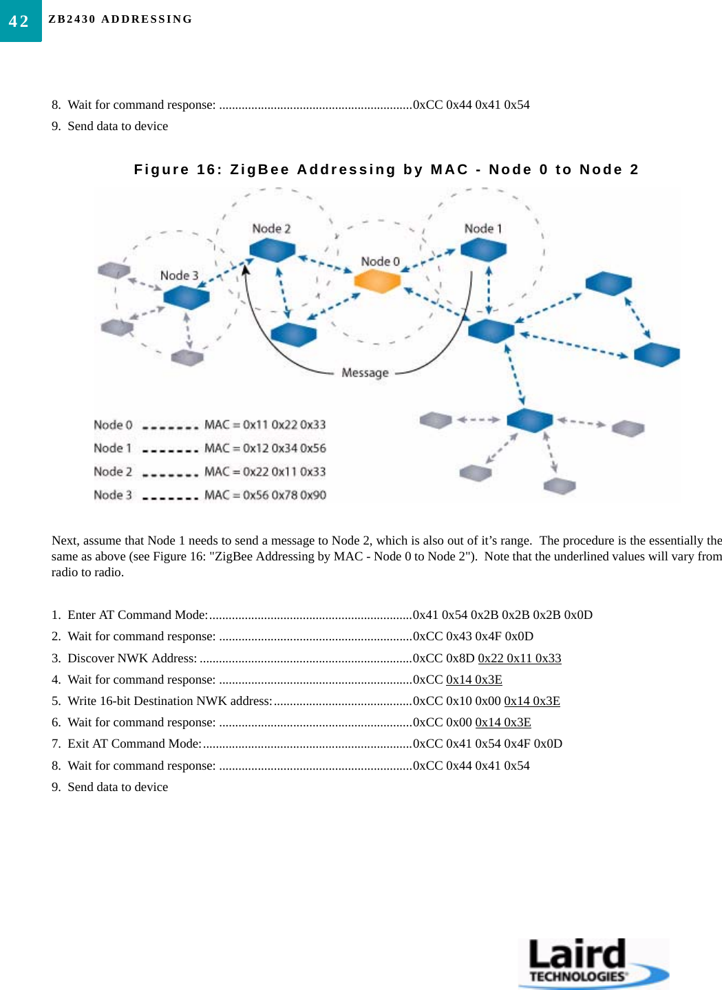
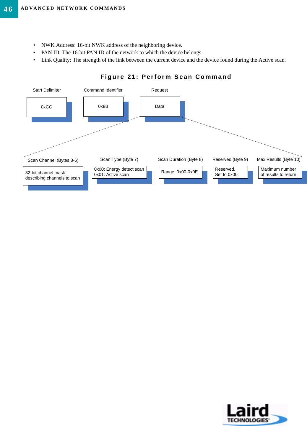
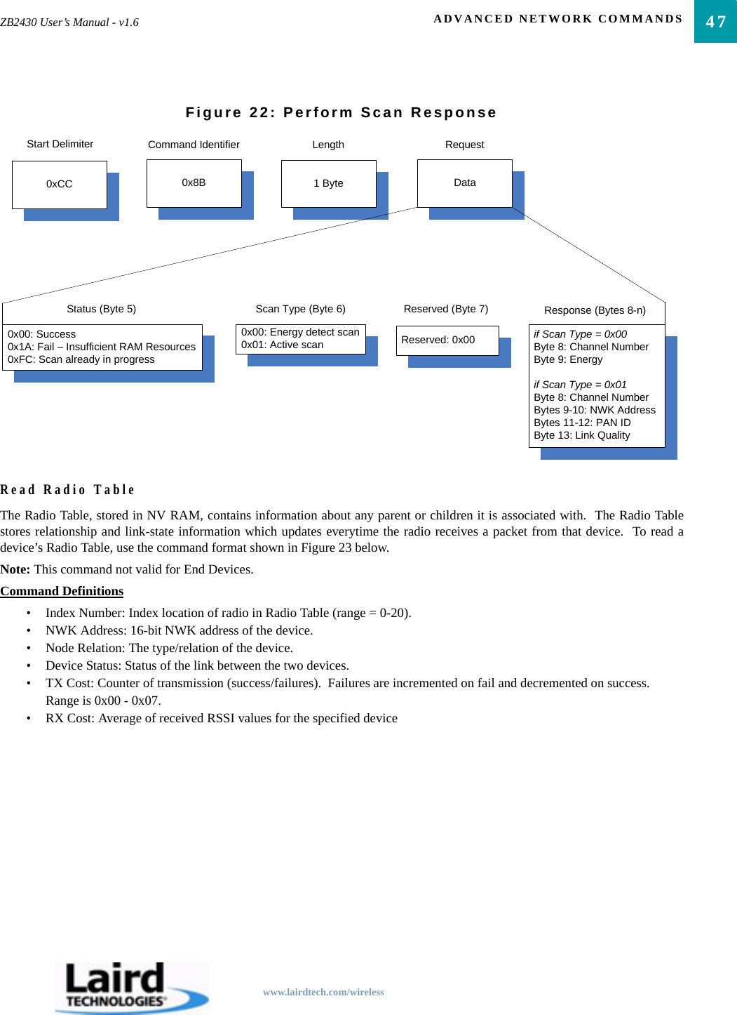
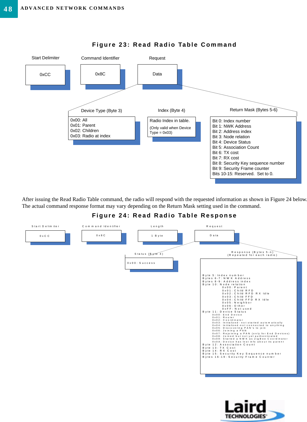
![CONFIGURING THE ZB243028AT COMMANDSThe AT Command mode implemented in the ZB2430 creates a virtual version of the Command/Data pin. The “Enter ATCommand Mode” Command asserts this virtual pin Low (to signify Command Mode) and the “Exit AT Command Mode”Command asserts this virtual pin High (to signify Data). Once this pin has been asserted Low, all On-the-Fly CC Commandsdocumented in the manual are supported.On-the-Fly Control CommandsThe ZB2430 transceiver contains static memory that holds many of the parameters that control the transceiver operation. Usingthe “CC” command set allows many of these parameters to be changed during system operation. Because the memory thesecommands affect is static, when the transceiver is reset, these parameters will revert back to the settings stored in the EEPROM. While in Command mode, the incoming RF interface of the transceiver is active and packets sent from other transceivers will stillbe received; however no outgoing RF packets will be sent. The transceiver uses Interface Timeout/RF Packet Size to determinewhen a CC Command is complete. Therefore, there should be no delay between each character as it is sent from the OEM Host tothe transceiver or the transceiver will not recognize the command.When an invalid command is sent, the radio discards the data and no response is sent to the OEM Host. Table 8 below shows aquick summary of the basic configuration & diagnostic commands available on the ZB2430. For detailed command information,please refer to the command descriptions immediatly following the Quick Reference Table.Table 8: Command Quick ReferenceCommand Name Command (All bytes in Hex) Return (All bytes in Hex)Enter AT Command Mode <0x41> <0x54> <0x2B> <0x2B> <0x2B> <0x0D> <0xCC> <0x43> <0x4F> <0x4D>Exit AT Command Mode <0xCC> <0x41> <0x54> <0x4F> <0x0D> <0xCC> <0x44> <0x41> <0x54>Status Request <0xCC> <0x00> <0x00> <0xCC> <Firmware> <Status>Read Channel <0xCC> <0x02> <0xCC> <Channel> <Channel Mask [3-0]>Write Destination NWK Address <0xCC> <0x10> <0x00> <NWK Hi> <NWK Lo> <0xCC> <0x00> <NWK Hi> <NWK Lo>Read Destination NWK Address <0xCC> <0x11> <0xCC> <0x00> <NWK Hi> <NWK Lo>Auto Destination <0xCC> <0x15> <Data> <0xCC> <Data>Read API Control <0xCC> <0x16> <0xCC> <API Control>Write API Control <0xCC> <0x17> <API Control> <0xCC> <API Control>Read Digital Input <0xCC> <0x20> <0xCC> <Data>Read ADC <0xCC> <0x21> <Data> <0xCC> <ADC Hi> <ADC Lo>Write Digital Outputs <0xCC> <0x23> <Data> <0xCC> <Data>Set Power Control <0xCC> <0x25> <Power> <0xCC> <Power>Read NWK Address <0xCC> <0x8A> <0x00> <0xCC> <0x8A> <NWK Hi> <NWK Lo>Read Parent’s NWK Address <0xCC> <0x8A> <0x01> <0xCC> <0x8A> <NWK Hi> <NWK Lo>Discover NWK Address <0xCC> <0x8D> <MAC [2-0]> <Data> <0xCC> <NWK Hi> <NWK Lo> <Data [n-0]>Discover IEEE Address <0xCC> <0x8E> <NWK Hi> <NWK Lo> <Data> <0xCC> <MAC [7-0]> <Data [n-0]>Read Temperature <0xCC> <0xA4> <0xCC> <Temperature [1-0]>](https://usermanual.wiki/Ezurio/Z100S1XFX.User-Manual/User-Guide-1045308-Page-32.png)
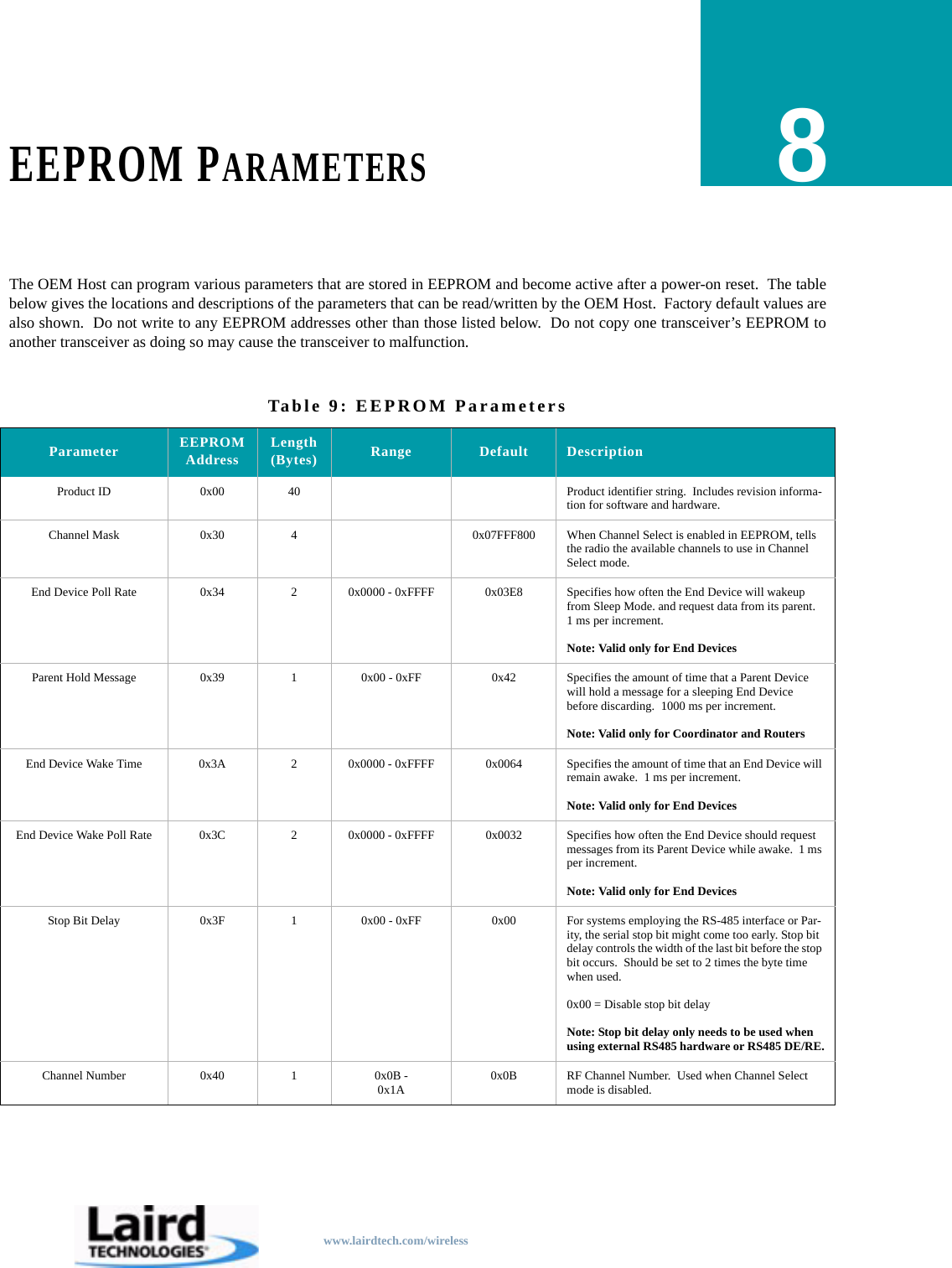
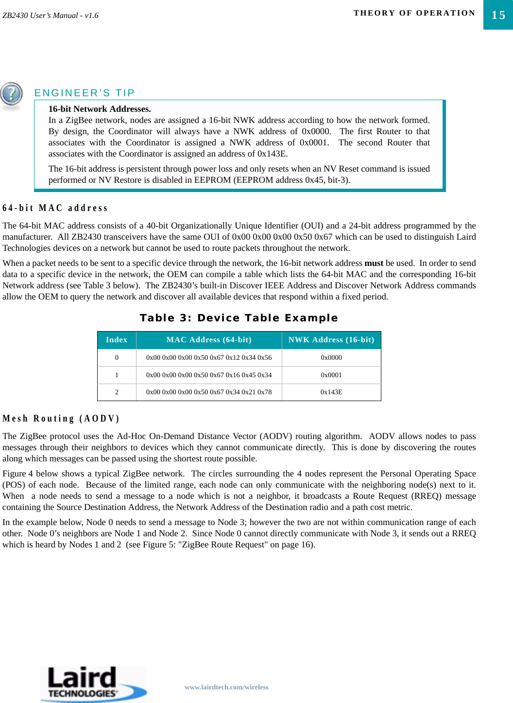
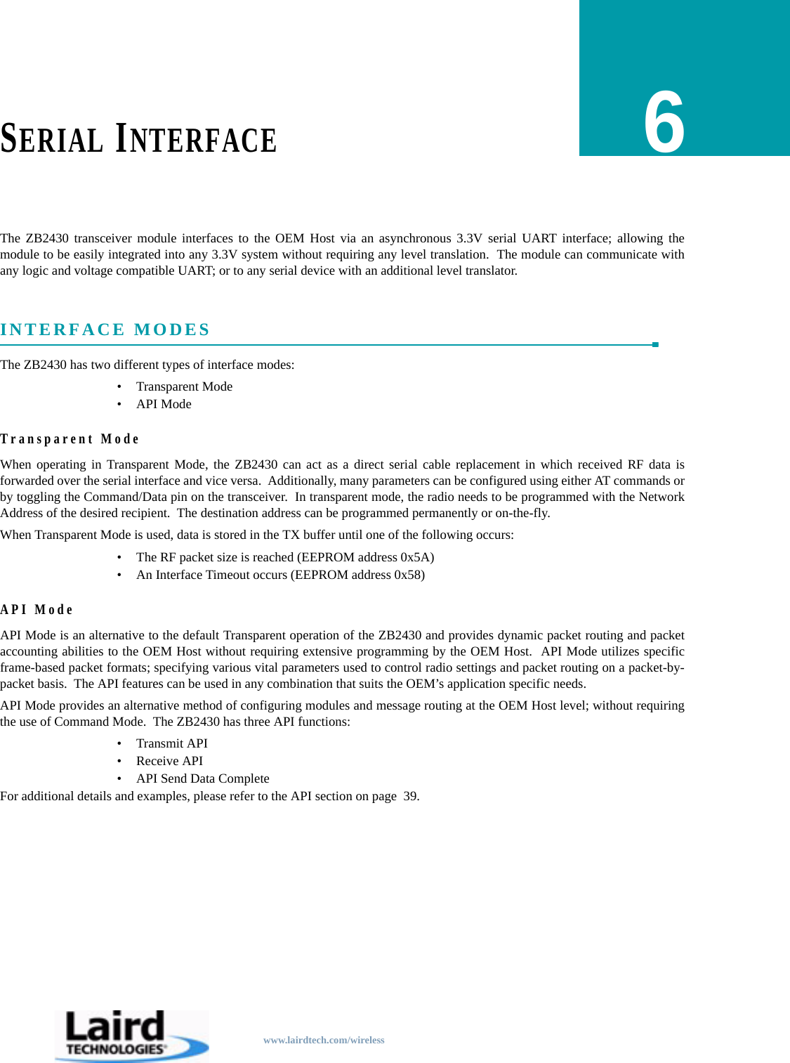
![29ZB2430 User’s Manual - v1.6 CONFIGURING THE ZB2430www.lairdtech.com/wirelessCOMMAND DESCRIPTIONSEEPROM Byte Read <0xCC> <0xC0> <Start> <Length> <0xCC> <Start> <Length> <Data [n-0]>EEPROM Byte Write <0xCC> <0xC1> <Start> <Length> <Data> <Start> <Length> <Last byte written>Soft Reset <0xCC> <0xFF> NoneSoft Reset with NV reset <0xCC> <0xFF> <0xE3> NoneRestore Factory Defaults <0xCC> <0xFF> <0xDF> NoneEnter AT Command ModePrior to sending this command, the OEM Host must ensure that thetransceiver’s RF transmit buffer is empty. This can be accomplished bywaiting up to one second between the last packet and the AT command. Ifthe buffer is not empty, the radio will interpret the command as data and itwill be sent over the RF. Command: <0x41> <0x54> <0x2B> <0x2B> <0x2B> <0x0D>Number of Bytes Returned: 4Response: <0xCC> <0x43> <0x4F> <0x4D>Exit AT Command ModeThe OEM Host should send this command to exit AT Command mode andresume normal operation.Command: <0xCC> <0x41> <0x54> <0x4F> <0x0D>Number of Bytes Returned: 4Response: <0xCC> <0x44> <0x41> <0x54>Status Version RequestThe OEM Host issues this command to request the firmware and link statusof the transceiver.Command: <0xCC> <0x00> <0x00>Number of bytes returned: 3Response: <0xCC> <Firmware> <Type>Parameter Range:<Firmware> = Radio Firmware version eg: 0x17 = v1.7<Type> = 0x00: End Device0x01: Router0x02: Coordinator0x03: Initialized - not started automatically0x04: Initialized - not connected to anything0x05: Discovering PAN’s to join0x06: Joining a PAN0x07: Rejoining a PAN (only for End Devices)0x08: Joined but not yet authenticated0x09: Started a NWK as ZigBee Coordinator0x0A: Device has lost info about its parentRead ChannelTable 8: Command Quick ReferenceCommand Name Command (All bytes in Hex) Return (All bytes in Hex)](https://usermanual.wiki/Ezurio/Z100S1XFX.User-Manual/User-Guide-1045308-Page-33.png)
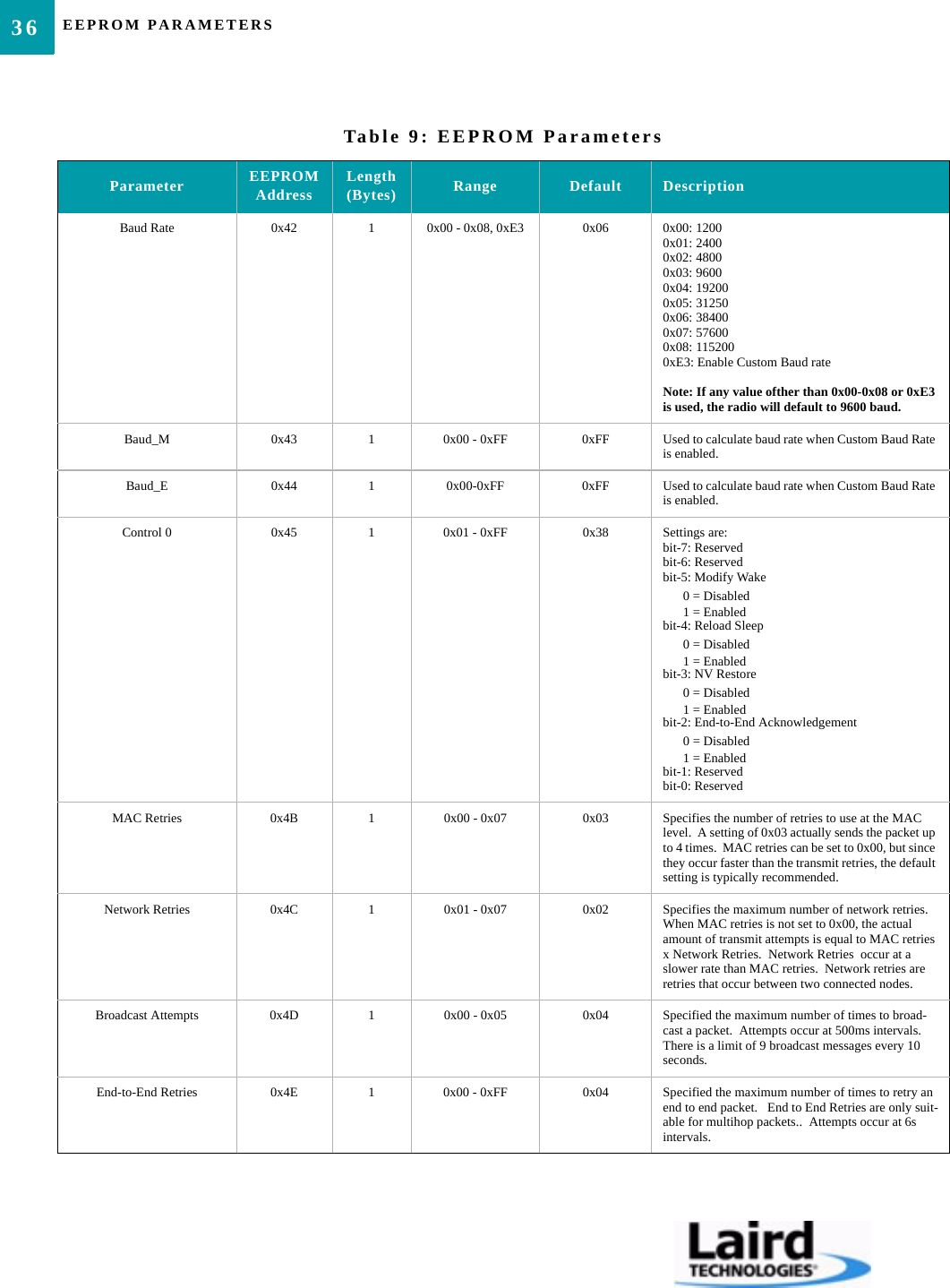
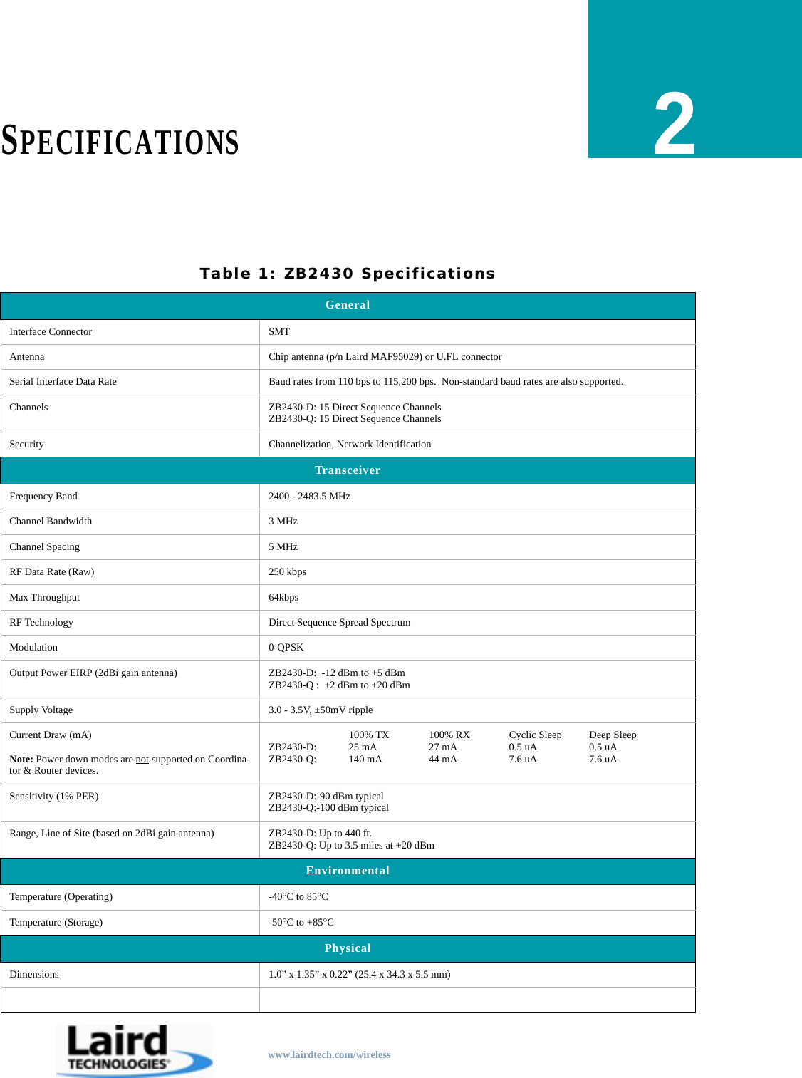
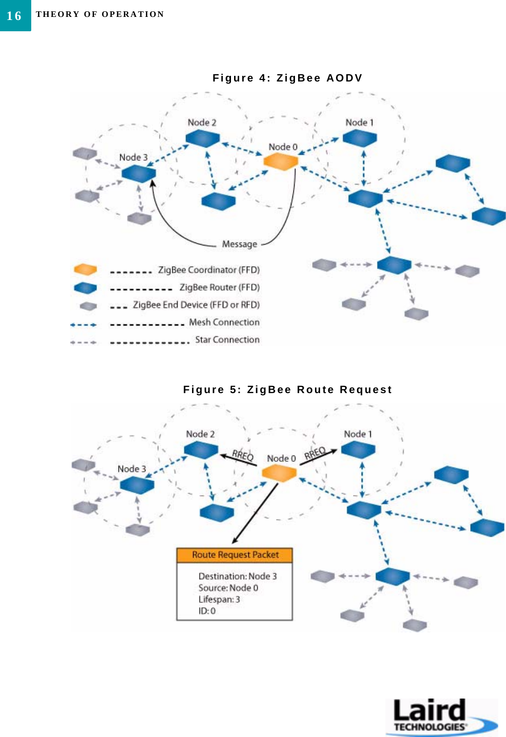
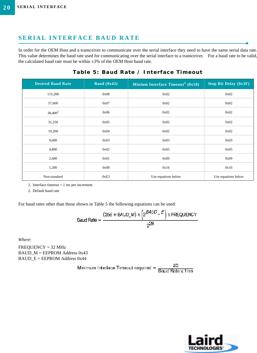
![31ZB2430 User’s Manual - v1.6 CONFIGURING THE ZB2430www.lairdtech.com/wirelessWrite API ControlThe OEM Host issues this command to write the API Control byte to enableor disable the API features.Command: <0xCC> <0x17> <API Control>Number of Bytes Returned: 2Response: <0xCC> <API Control>Parameter Range:<API Control>= bits 7-3: Ignoredbit-2: Send Data Completebit-1: Transmit APIbit-0: Receive APIRead Digital InputThe OEM Host issues this command to read the state of GI0 input pins. Pinsconfigured as outputs will report their current state.Command: <0xCC> <0x20>Number of Bytes Returned: 2Response: <0xCC> <Digital In>Parameter Range:<Digital In> = bit-0: GI0Read ADCThe OEM Host issues this command to read the onboard 12-bit A/Dconverters.This command allows a very detailed amount of customization. The OEMHost can select which pin or sensor to monitor, the resolution of themeasurement and the reference voltage to measure the input ADC against. Greater Resolution will provide a more detailed response, but will introduceadditional latency.The following equations can be used to determine the voltages associatedwith the ADC value returned:Command:<0xCC> <0x21> <Channel> <Resolution> <Ref>Number of bytes Returned: 3Response: <0xCC> <Hi ADC> <Lo ADC>Parameter Range:<Channel> = 0x00: Cmd/Data0x01: InRange 0x02: GI030x03: GI040x04: GI050x05: GI060x06: GI07 0x07: GI080x0D: Positive Voltage Reference = 1.25V0x0E: Temperature Sensor0x0F: Vdd <Resolution> = 0x00: 8 bit resolution [RES=0x00FF]0x01: 10 bit resoltution[RES=0x03FF]0x02: 12 bit resolution [RES=0x0FFF]0x03: 14 bit resolution [RES=0x3FFF]<Reference> = 0x00: Internal 1.25V [REFvoltage= 1.25V]0x01: External Reference on GI080x02: Vdd0x03: Differential between pins GI07 and Gi08<Hi ADC> = MSB of requested 12-bit ADC value<Lo ADC> = LSB of requested 12-bit ADC valueWrite Digital OutputsADIn ADC valueRES[]---------------------------⎝⎠⎛⎞= REFvoltage[]×](https://usermanual.wiki/Ezurio/Z100S1XFX.User-Manual/User-Guide-1045308-Page-35.png)
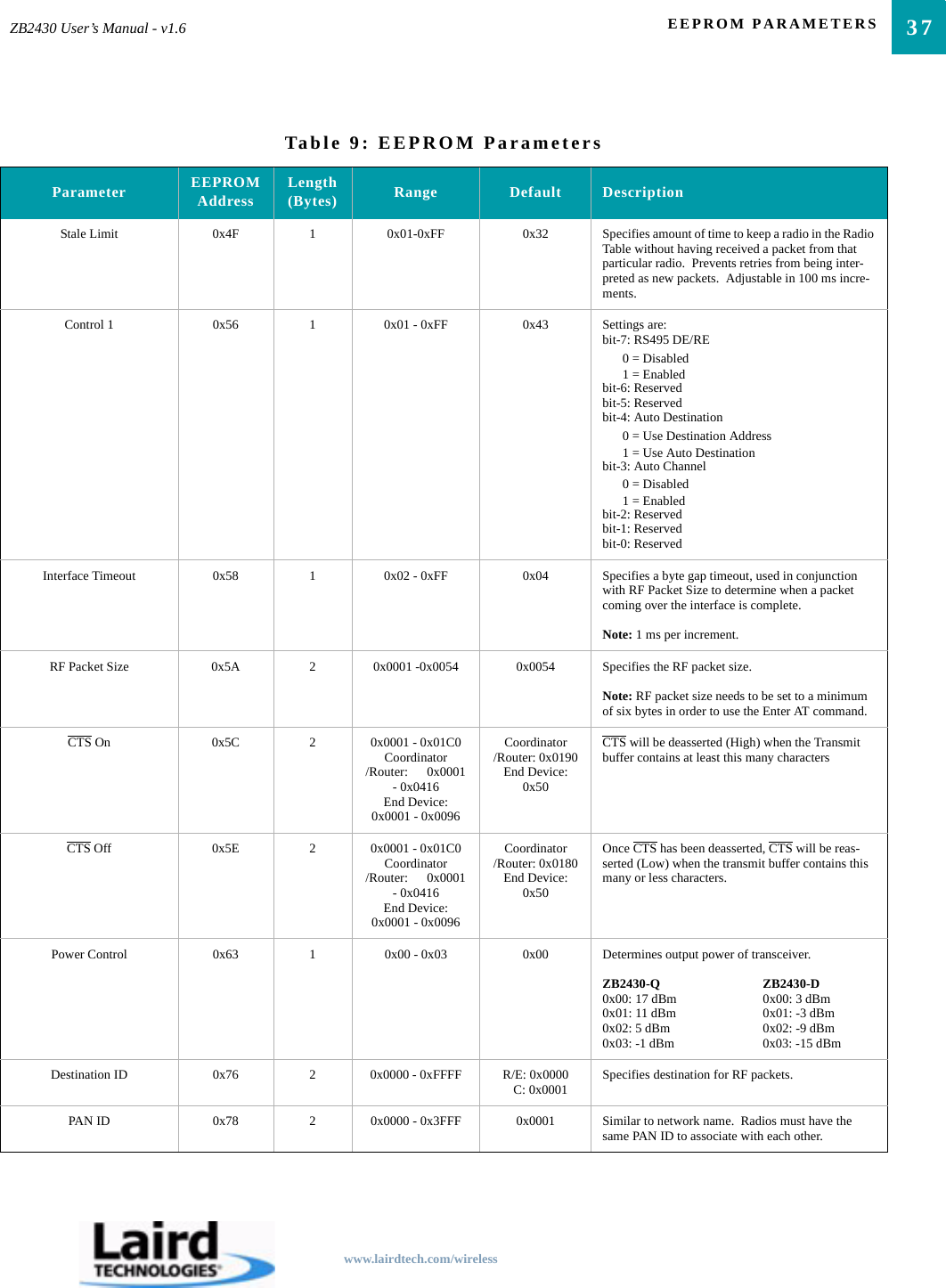
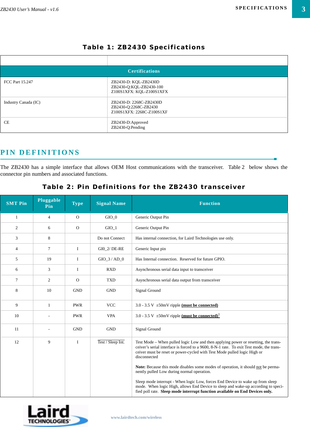
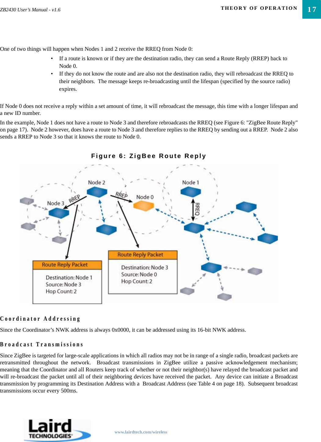
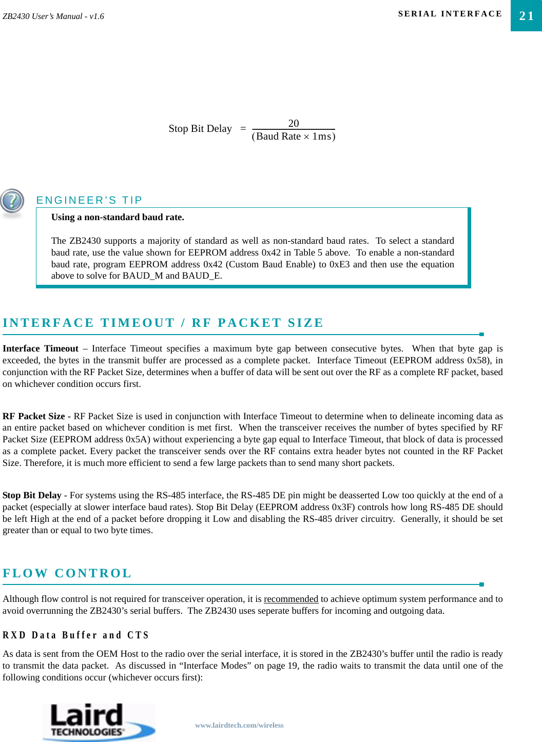
![CONFIGURING THE ZB243032The OEM Host issues this command to write both digital output lines toparticular states.The OEM Host must write the value of all digital outputs at once. Each bitrepresents a GIO. The first 8 bits are resserved and not in use.Command: <0xCC> <0x23> <Digital Out[1-0]>Number of Bytes Returned: 2Response: 0xCC <Digital Out [1-0]>Parameter Range:<Digital Out> = bit-0: GO0bit-1: GO1bit-2: GO2bit-3: GO3bit-4: GO4bit-5: GO5bit-6: GO6bit-7: GO7bit-8-15 : ReservedSet Max PowerThe OEM Host issues this command to adjust the maximum output power. Command: <0xCC> <0x25> <Max Pwr>Number of Bytes Returned: 2Response: 0xCC <Max Pwr>Parameter Range:<Max Pwr> = High Power Low Power0x00: 17 dBm 0x00: 3 dBm0x01: 11 dBm 0x01: -3 dBm0x02: 5 dBm 0x02: -9 dBm0x03: -1 dBm 0x03: -15 dBmRead 16-bit NWK AddressThe OEM Host issues this command to determine the 16-bit NWK addressof the device it is connected to.Command: <0xCC> <0x8A> <0x00>Number of Bytes Returned: 4Response: <0xCC> <0x8A> <NWK Hi> <NWK Lo>Parameter Range:<NWK Hi> = MSB of radio’s NWK address<NWK Lo> = LSB of radio’s NWK addressNote: If the device has not yet been assigned, a NWK address of 0xFFFFwill be returned.Read 16-bit NWK Address of Parent DeviceThe OEM Host issues this command to determine the 16-bit NWK addressof its’ Parent Device.Command: <0xCC> <0x8A> <0x01>Number of Bytes Returned: 4Response: <0xCC> <0x8A> <NWK Hi> <NWK Lo>Parameter Range:<NWK Hi> = MSB of Parent’s NWK address<NWK Lo> = LSB of Parent’s NWK addressNote: If the device has not yet associated, a NWK address of 0xFFFF willbe returned.Discover 16-bit NWK Address of Remote Radio](https://usermanual.wiki/Ezurio/Z100S1XFX.User-Manual/User-Guide-1045308-Page-36.png)
![33ZB2430 User’s Manual - v1.6 CONFIGURING THE ZB2430www.lairdtech.com/wirelessThe OEM Host issues this command to discover the 16-bit NWK address ofa remote radio.Note: This command is valid only for Coordinators and/or Router devices.This command will not issue a response if the requested address is unable tobe located in the network. A timeout of several seconds should be assumedwhen using this command.Command: <0xCC> <0x8D> <IEEE [7-0]>Number of Bytes Returned: 3Response: <0xCC> <NWK Hi> <NWK Lo> Parameter Range:<IEEE> = 64-bit IEEE Address of remote radio<NWK Hi> = MSB of remote radio’s NWK address<NWK Lo> = LSB of remote radio’s NWK addressDiscover IEEE Address of Remote RadioThe OEM Host issues this command to discover the 64-bit IEEE address ofa remote radio.Note: This command is valid only for Coordinators and/or Router devices.This command will not issue a response if the requested address is unable tobe located in the network. A timeout of several seconds should be assumedwhen using this command.Command: <0xCC> <0x8E> <0x00> <NWK Hi> <NWK Lo>Number of Bytes Returned: 9Response: <0xCC> <IEEE [7-0]> Parameter Range:<NWK Hi> = MSB of remote radio’s NWK address<NWK Lo> = LSB of remote radio’s NWK address<IEEE> = 64-bit IEEE Address of remote radioDiscover IEEE Address & Children of Remote RadioThe OEM Host issues this command to discover the 64-bit IEEE address ofa remote radio as well as report a list of that device’s Children.Note: This command is valid only for Coordinators and/or Router devices.This command will not issue a response if the requested address is unable tobe located in the network. A timeout of several seconds should be assumedwhen using this command.Command: <0xCC> <0x8E> <0x00> <NWK Hi> <NWK Lo> <0x01>Number of Bytes Returned: 10+Response: <0xCC> <IEEE [7-0]> <Length> <List>Parameter Range:<NWK Hi> = MSB of remote radio’s NWK address<NWK Lo> = LSB of remote radio’s NWK address<IEEE> = 64-bit IEEE Address of remote radio<Length> = Length of data to follow<List> = List of remote radio’s associated devices [<Index n> <NWK Hi n> <NWK Lo n>]Read TemperatureThe OEM Host issues this command to read the onboard temperature sensor.Note: The temperature sensor is uncalibrated and has a tolerance of +/- 3C.For calibration instructions, contact Laird Technologies’s technical support.Command: <0xCC> <0xA4>Number of bytes returned: 3Response: 0xCC <+/-> <Temp.>Parameter Range:<+/-> = 0x2B: +0x2D: -<Temp.> = Temperature (Celsius) (0x08 - 0x50)Read VoltageThe OEM Hosts issues this command to read the input voltage to the radio. Command: <0xCC> <0xA6>Number of Bytes Returned: 2Response: <0xCC> <Voltage Integer> <Voltage Decimal>Parameter Range:<Voltage Integer>=Integer portion of voltage reading<Voltage Decimal>=Decimal portion of voltage readingExample Output: 0xCC 0x03 0x37<0x03> =Integer portion is 3v<0x37> =decimal portion is .55vVoltage level is 3.55V](https://usermanual.wiki/Ezurio/Z100S1XFX.User-Manual/User-Guide-1045308-Page-37.png)