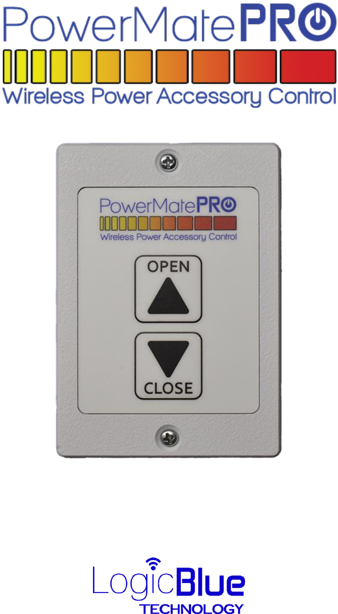
FBA Operating POWERMATEPRO Bluetooth vehicle accessory remote control User Manual
Command Electronics, LLC Bluetooth vehicle accessory remote control
User Manual
User Manual
Hickory, North Carolina USA
1
Limited Warranty
The warranty obligations of LogicBlue Technology (“LogicBlue”) for this product are limited to
the terms set forth below.
What is Covered
This limited warranty covers defects in the materials and workmanship in this product.
What is not Covered
This limited warranty does not cover any damage, deterioration or malfunction resulting from
any alteration, modification, improper or unreasonable use or maintenance, misuse, abuse,
accident, neglect, exposure to excess moisture, fire, lightning, power surges, or other acts of
nature. This limited warranty does not cover any damage, deterioration or malfunction
resulting from the installation or removal of this product from any installation, any
unauthorized tampering with this product, any repairs attempted by anyone unauthorized by
LogicBlue to make such repairs, or any other cause which does not relate directly to a defect in
materials and/or workmanship of this product. Without limiting any other exclusion herein,
LogicBlue does not warrant that the product covered hereby, including, without limitation, the
technology and/or integrated circuit(s) included in the product, will not become obsolete or
that such items are or will remain compatible with any other product or technology with which
the product may be used.
How Long this Coverage Lasts
The limited warranty for LogicBlue products is 1 year from the original date of purchase. Proof
of purchase from the customer will be required for all warranty claims.
Who is Covered
Only the original purchaser of this product is covered under this limited warranty. This limited
warranty is not transferable to subsequent purchasers or owners of this product.
What LogicBlue Will Do
LogicBlue will, at its sole discretion, will repair or replace the product determined to be
defective with regard to materials or workmanship.

2
As with all electronic devices, they are susceptible to damage by static electricity
discharge. Before handling or installing this product, be sure to discharge the static
electricity in your body by touching a piece of grounded metal.
FCC Statement
This device complies with Part 15 of the FCC Rules. Operation is subject to the following two conditions:
(1) this device may not cause harmful interference, and
(2) this device must accept any interference received, including interference that may cause
undesired operation.
Note: This equipment has been tested and found to comply with the limits for a Class B digital device,
pursuant to part 15 of the FCC Rules. These limits are designed to provide reasonable protection against
harmful interference in a residential installation. This equipment generates, uses and can radiate radio
frequency energy and, if not installed and used in accordance with the instructions, may cause harmful
interference to radio communications. However, there is no guarantee that interference will not occur in
a particular installation. If this equipment does cause harmful interference to radio or television reception,
which can be determined by turning the equipment off and on, the user is encouraged to try to correct
the interference by one or more of the following measures:
—Reorient or relocate the receiving antenna.
—Increase the separation between the equipment and receiver.
—Connect the equipment into an outlet on a circuit different from that to which the receiver is
connected.
—Consult the dealer or an experienced radio/TV technician for help.
Changes or modifications not expressly approved by Command Electronics, LLC could void the
user's authority to operate the equipment.
Industry Canada Statement
This device complies with Industry Canada licence-exempt RSS standard(s). Operation is subject to the
following two conditions:
(1) this device may not cause interference, and
(2) this device must accept any interference, including interference that may cause undesired
operation of the device.
Le présent appareil est conforme aux CNR d'Industrie Canada applicables aux appareils radio exempts de
licence. L'exploitation est autorisée aux deux conditions suivantes :
(1) l'appareil ne doit pas produire de brouillage, et
(2) l'utilisateur de l'appareil doit accepter tout brouillage radioélectrique subi, même si le
brouillage est susceptible d'en compromettre le fonctionnement.
3
IMPORTANT! READ THIS SECTION
Prior to Starting Installation of your PowerMatePro:
To allow for testing the operation of the slide or awning after installation of the
PowerMatePro, position your slide or awning midway open prior to power disconnection.
Installation of the PowerMatePro will involve electrical connections relating to your power slide
system or power awning. These electrical connections are used to control the DC motor that
operates your slide or awning. These electrical connections utilize relatively large amounts of
electrical current, typically greater than 10 amps.
It is important that prior to you installing the PowerMatePro, DISCONNECT ALL POWER
SOURCES TO YOUR RV INCLUDING EXTERNAL 120 VOLT AC POWER AND THE 12 VOLT
BATTERY.
FAILURE TO DISCONNECT ALL EXTERNAL AND INTERNAL POWER
SOURCES PRIOR TO INSTALLATION COULD RESULT IN FIRE OR OTHER
SEVERE DAMAGE TO YOUR RV DURING THE INSTALLATION PROCESS.
Read this manual completely prior to the start of your installation. The
PowerMatePro is designed to replace traditional polarity reversing rocker
switches (see next section). If your installation uses a different type of switch or
uses an electronic controller, contact our technical service department prior to
proceeding with this installation for assistance.
4
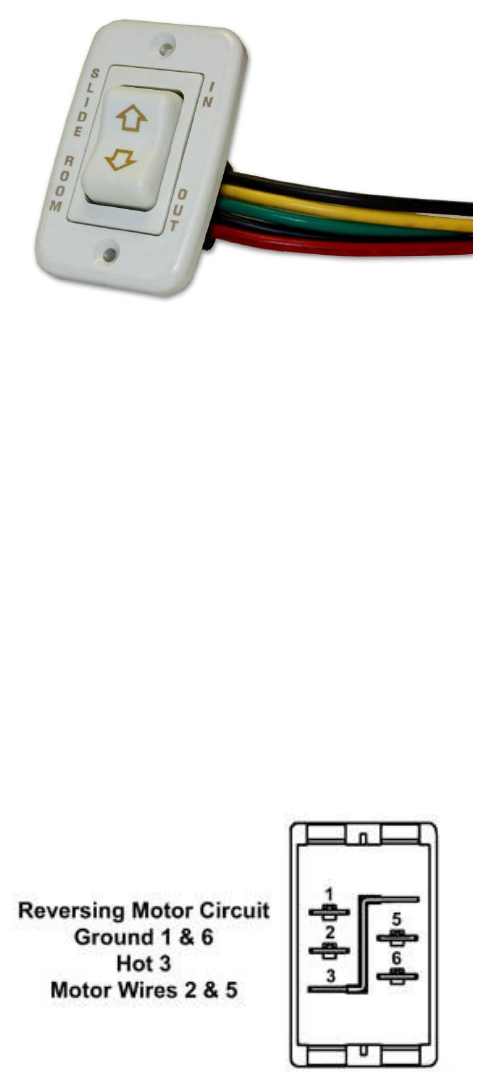
PowerMatePro to Replace an Existing Slide or Awning Switch
PowerMatePro was designed to replace an existing rocker type switch used to control a slide or
awning operation. A typical factory installed rocker switch is pictured below:
Figure 1
These types of switches are used for “polarity reversing”. By changing the polarity of the motor
wires (changing which motor wire is connected to +12 volts and Negative), the direction of
travel for the slide or awning is reversed.
Most of these types of switches are connected with a plug-in harness that typically has 5 wires
as shown. These wires are used as follows:
• Red - +12 VDC
• Black (2) – Negative or ground
• Green – Motor Wire 1
• Yellow – Motor Wire 2
The back of the switch, with the connector unplugged, looks like the image below:
Figure 2
5
PowerMatePro Mounting Hole
The PowerMatePro requires a mounting hole that may be larger than the current hole for the
existing switch. The minimum mounting hole required for the PowerMatePro is 1.75” (~45
mm) wide by 2.5” (~64 mm) high. If the existing mounting hole is smaller than that required,
complete the following:
1. Unplug the existing rocker switch from the plug-in cable harness.
2. If there is excess wire within the wall, pull the plug-in harness out of the wall so that the
harness does not fall back inside the wall cavity. If the cable falls inside the wall cavity,
it may be very difficult to retrieve.
3. A cut-out template is printed in the back of this manual. Tear or cut the template page
from the manual. Using scissors or a utility knife, cut out the rectangular opening in the
template that sizes the required hole dimensions. Tape this cutout template over the
existing hole, positioning it to minimize the amount of cutting required. Be sure that the
top of the template outline is parallel to the floor/ceiling. Outline the section to be cut
with a pen, pencil or fine point marker.
4. Using a keyhole or drywall hand saw, enlarge the existing hole in width and/or height to
match the opening in the template. Be sure not to enlarge the hole too high or the
mounting plate screws will not have wall material to be secured to. Do not enlarge
the hole too wide or the mounting plate will not cover the hole. WARNING! DO NOT
ACCIDENTLY CUT THE PLUG-IN HARNESS WIRES.
5. You may optionally drill the holes for the two mounting screws. Use a 7/64ths drill bit
and drill two pilot holes, each in the center of the template mounting hole pattern.
6. Remove the template overlay from the wall.
6
PowerMatePro Wiring
WARNING: BE SURE POWER IS REMOVED FROM THE SWITCH WIRING BEFORE CONTINUING!
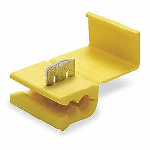
Your PowerMatePro has been furnished with four ScotchLok® tap and run crimp connectors
suitable for electrical connections of 10 to 12-gauge wiring. An example is pictured below:
Figure 3
The connector is designed to be used to tap into an existing wire without the need for cutting
or stripping the wires to be connected. The user snaps the connector with the open slot side
onto the existing wire to be tapped. The wire to be added to the circuit is inserted into one of
the adjacent holes such that the end of the new wire stops just past the metal plate. Use a pair
of pliers to drive the metal plate down into the wires until the top of the plate is flush with the
plastic. Close the plastic cover to complete the operation.
The PowerMatePro has four wires fixed to the circuit board. They are:
• Red – Positive power, +12 volts DC. Powers the PowerMatePro and the motor.
• Black – Negative (Ground).
• Blue – Motor Wires (2). Each blue wire connects to one of the motor wires.
To connect the PowerMatePro to the existing wiring harness, complete the following:
1. Slide a ScotchLok connector onto one of the motor wires, typically either green or
yellow. Position the connector a few inches away from the plug-in connector so that
there will be adequate loose wire for crimping.
2. Insert one of the blue wires from the PowerMatePro into the adjacent hole of the
connector so that the end of the wire is located past the metal plate.
3. Using a pair of pliers, compress the plate such that the top of the plate is flush with the
plastic body of the connector. Tug on the finished connection to verify a successful
crimp connection.
7
4. Repeat the above steps for the other motor wire (yellow or green) and use the second
blue wire from the PowerMatePro.
5. Repeat steps 1-3 using one of the black wires from the wire harness and the black wire
from the PowerMatePro.
6. Repeat steps 1-3 using the red wire from the wire harness and the red wire from the
PowerMatePro.
7. Using a few pieces of electrical tape, cover the open end of the plug-in wire harness
connector. This will help to prevent anything from accidently getting into the unused
harness connections.
Once all of the connections have been completed, the PowerMatePro can be installed into the
wall opening and secured into place with the two provided flat head screws.
Power can be re-connected to the RV electrical system. When power is applied, the
PowerMatePro will beep twice to indicate that the module is receiving power. The user can
press the OPEN or CLOSE button to operate the power slide or awning.
If the slide or awning operates backwards compared to the button activation (i.e. opens when
the CLOSE button is pressed), the relay operation can be configured from the smart device app
or through the keypad configuration mode (see Configuration Mode section) to change the
relay activation operation.
8
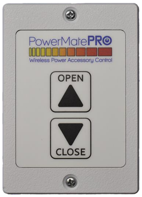
PowerMatePro Standard Operation
The PowerMatePro has two buttons for operation as shown below:
Figure 4
Open – Press the OPEN button to extend the slide or awning. The slide or awning will continue
to extend for as long as the button is held. Releasing the OPEN button will turn off the motor
and allow the slide or awning to coast to a stop.
Close – Press the CLOSE button to retract the slide or awning. The slide or awning will continue
to retract for as long as the button is held. Releasing the CLOSE button will turn off the motor
and allow the slide or awning to coast to a stop.
Note that when pressing either button, a momentary beep will occur.
WARNING – DO NOT CONTINUE TO OPERATE THE MOTOR FOR THE SLIDE OR AWNING BEYOND
THE FULLY EXTENDED OR FULLY RETRACTED POSITION. DOING SO MAY CAUSE PERMENENT
DAMAGE TO THE DRIVE MOTOR OR MECHANISM.
9
NOTE – The PowerMatePro has a built-in delay that is activated when either button is released
after depression. This delay is one (1) second in duration and applies ONLY if the opposite
button is depressed immediately. This functionality allows the motor to coast to a stop prior to
a change in direction.
Configuration Mode
The PowerMatePro can be placed into a configuration mode to complete the following:
1. Activate the “Learning” mode of the system so that the PowerMatePro can be
associated with a Smart Device.
2. To change the programmed relay direction operation. This function is used to change
the relay output operation if the button functionality is backwards.
To enter the Configuration mode, press and hold BOTH buttons at the same time for two (2)
seconds. The PowerMatePro will beep twice to indicate that the unit is in configuration mode.
NOTE: Entering Configuration mode ALSO activates “Learn” mode. The PowerMatePro can
now be associated with a Smart Device App for the next 10 minutes.
After the Configuration mode has been entered, the sounder will provide a long beep in 10
seconds of no button activity, indicating that the Configuration mode has been exited.
“Learn” mode will continue for the next 10 minutes.
Changing the Output Relay Direction Operation
If the OPEN and CLOSE buttons operate backwards after initial installation, the Output Relay
direction can be changed through the app or in the configuration mode. To change the Output
Relay direction directly from the PowerMatePro buttons, complete the following:
1. Enter the configuration mode as outlined in the section above.
2. Within 10 seconds of entering the configuration mode, press and hold the CLOSE button
for 2 seconds. After two seconds, the PowerMatePro will beep four (4) times and the
Output Relay direction will be reversed. The configuration mode will automatically exit.
NOTE: While the PowerMatePro is in configuration mode, the OPEN and CLOSE buttons will
not activate the motor functions.
10
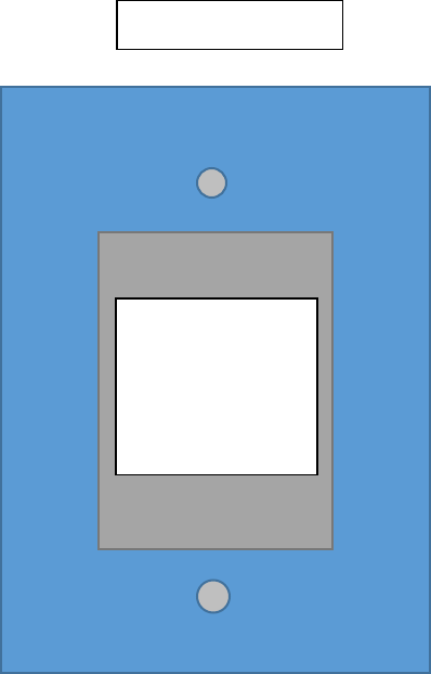
Cutout Template
Faceplate Outline
Cut the GREY
section out.
This is the
opening
required
11
Logic Blue Technology
1224 19th Street Lane NW.
Hickory, NC 28601
© 2018 Logic Blue Technology