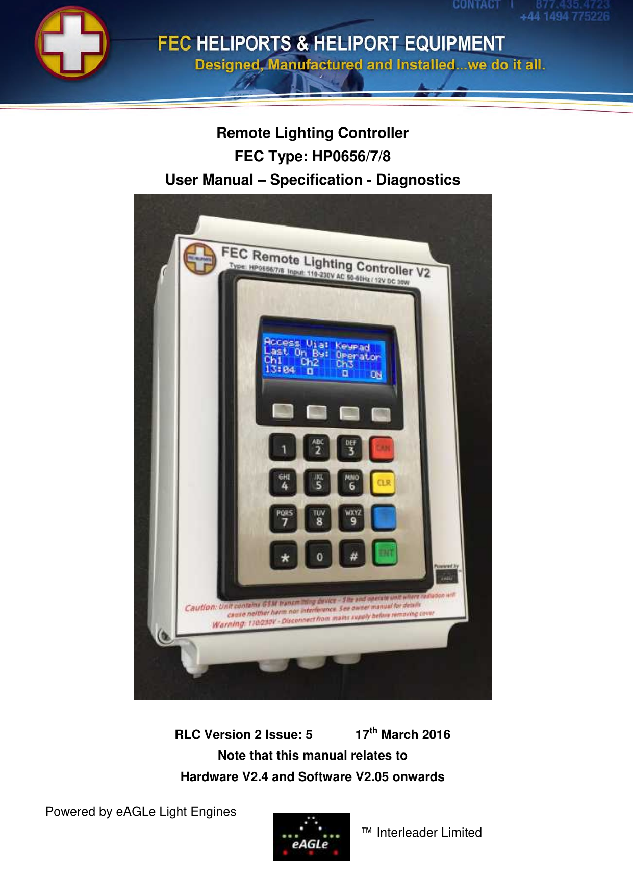
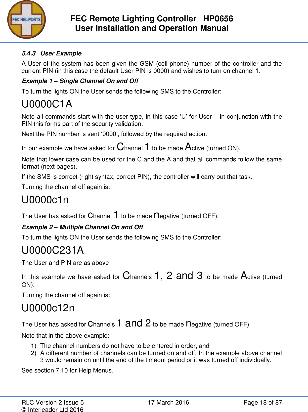
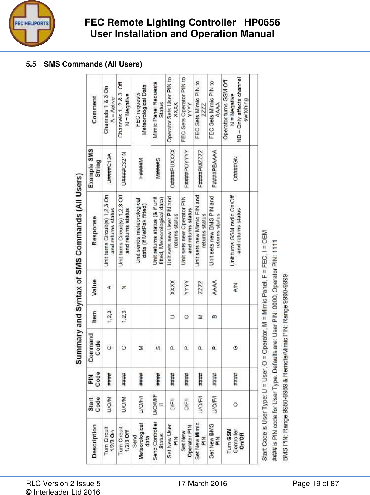
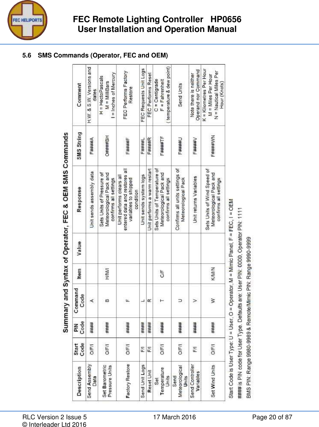
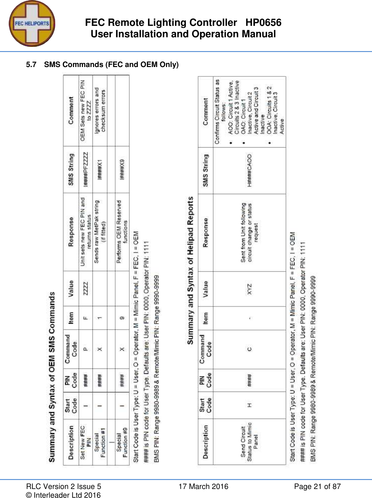
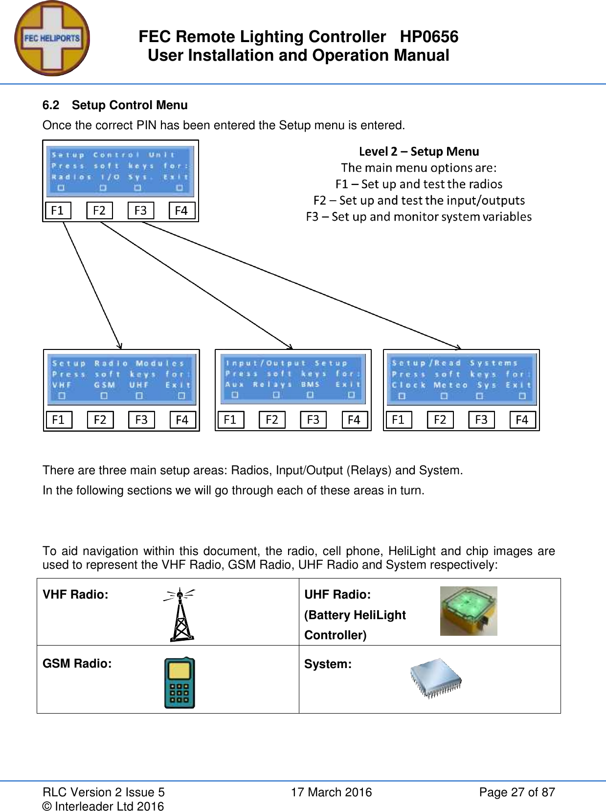
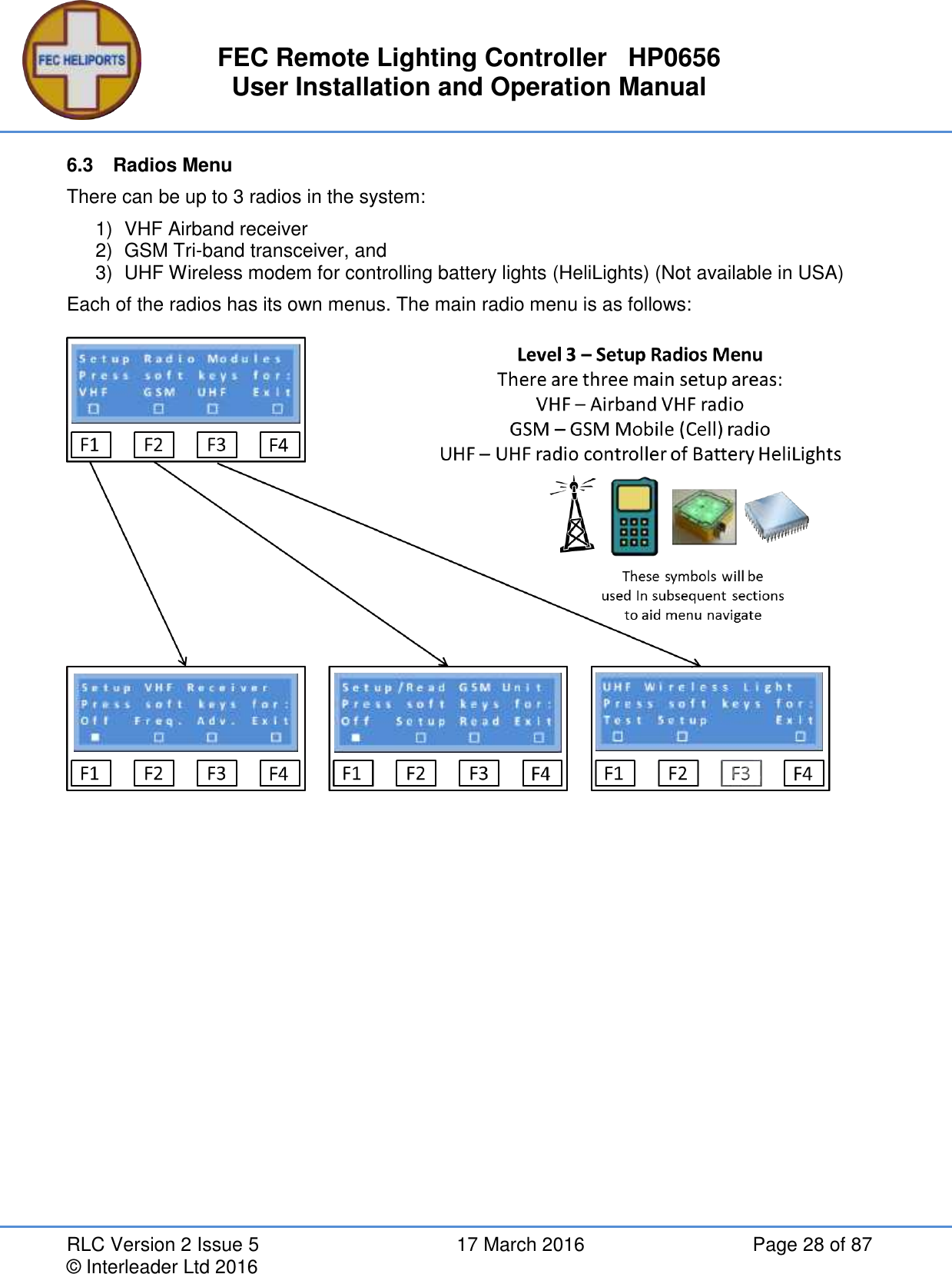
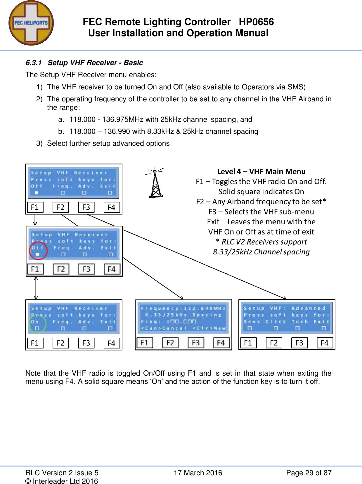
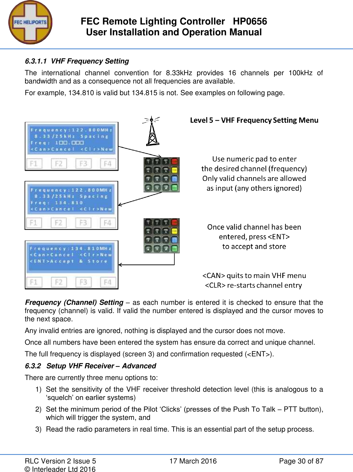
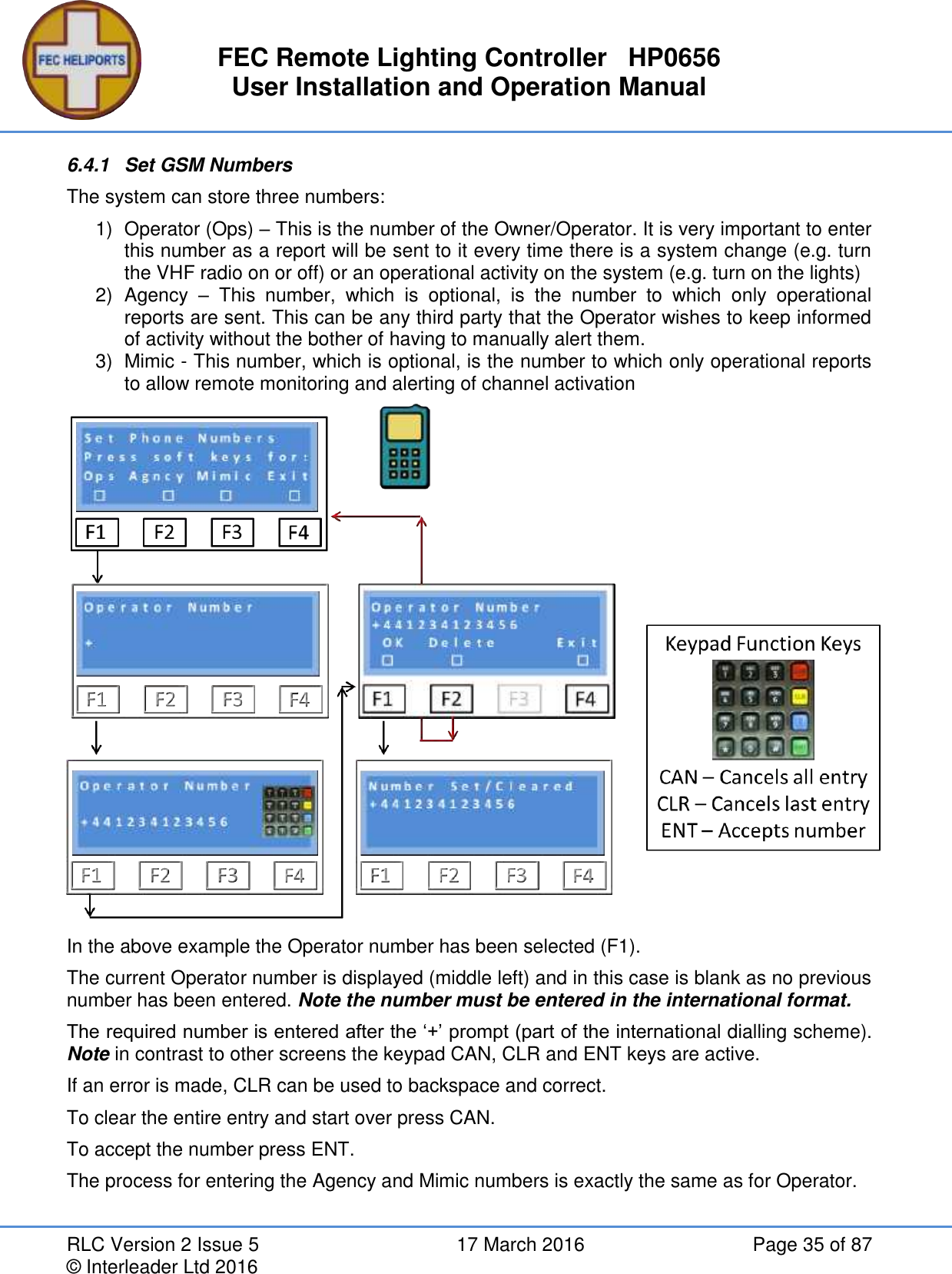
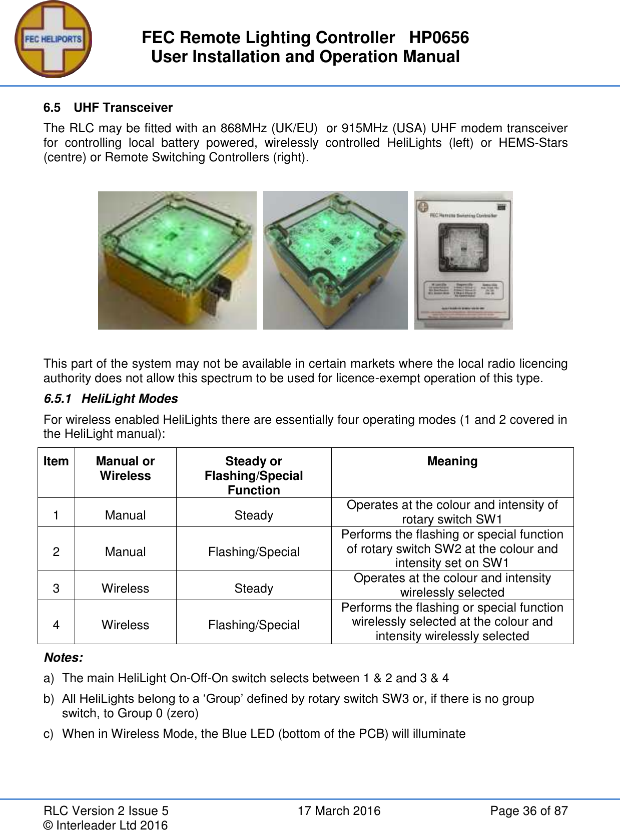
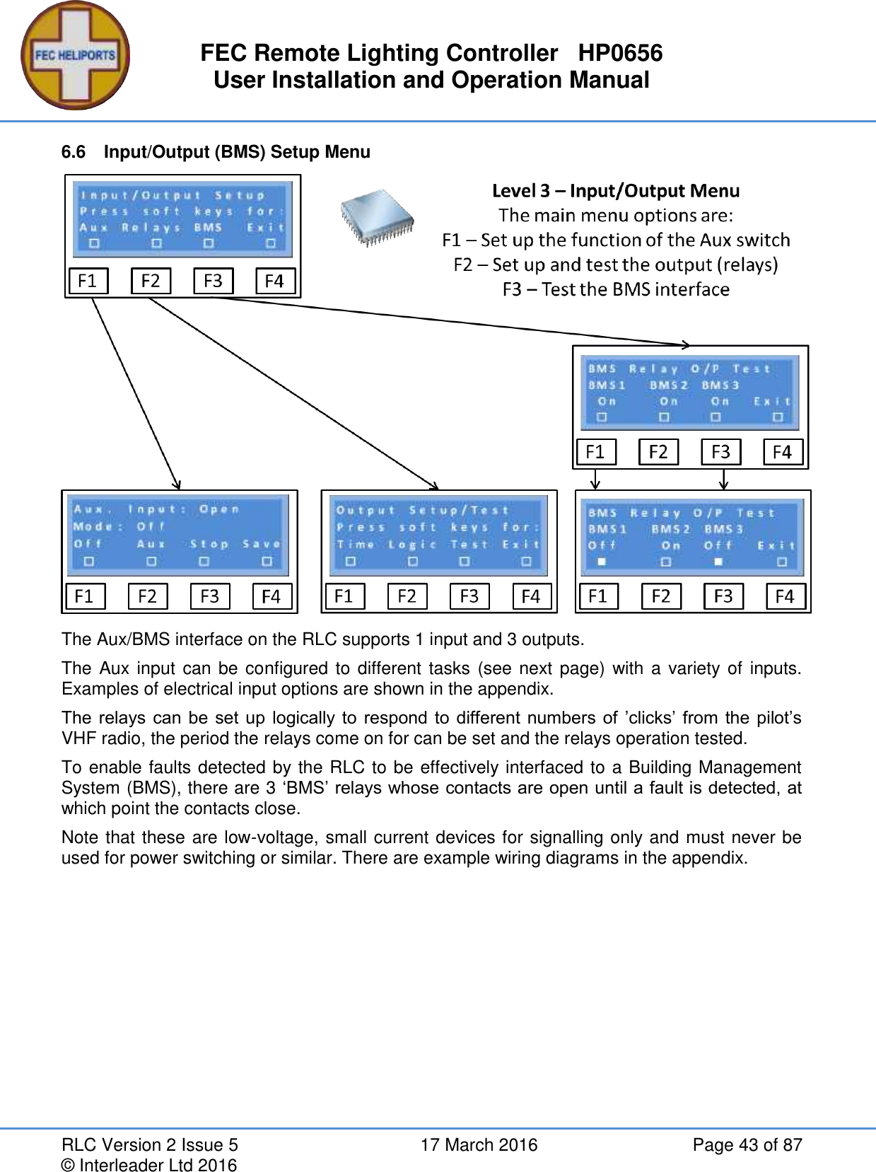
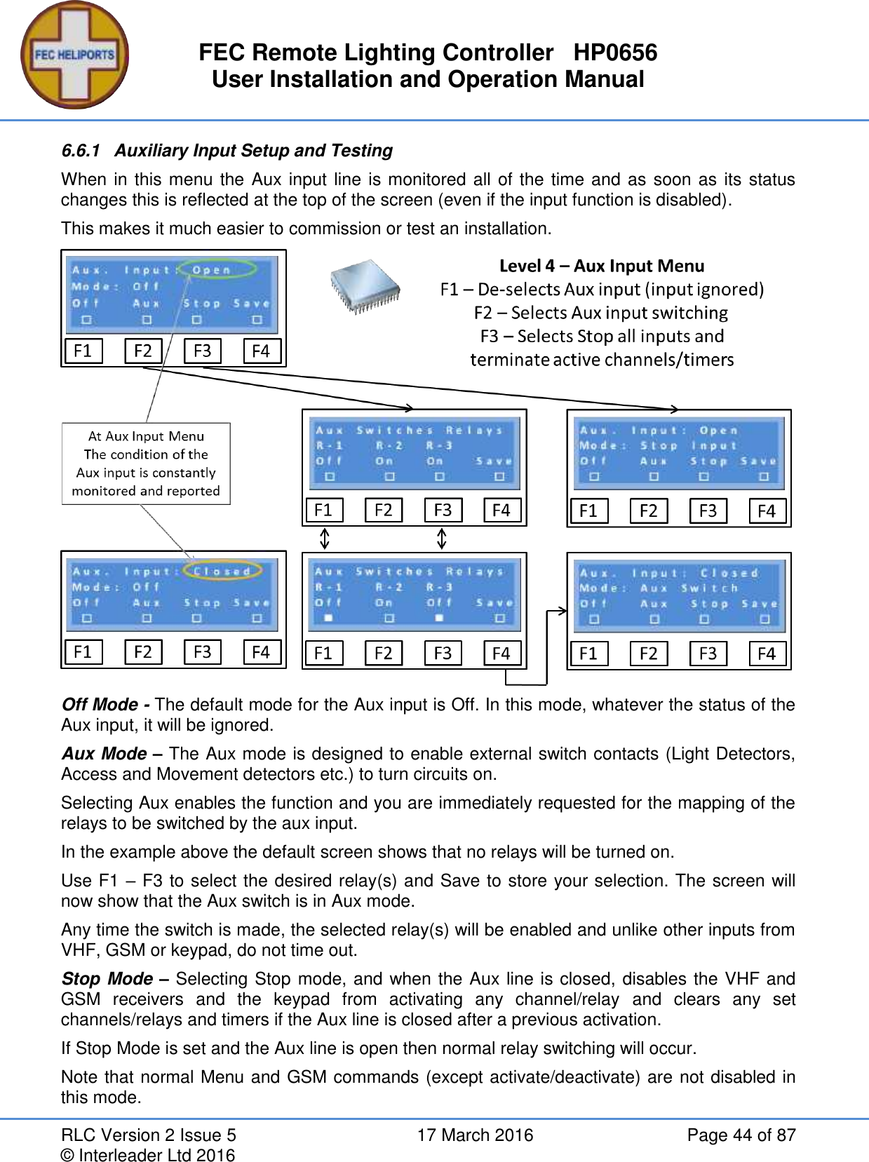
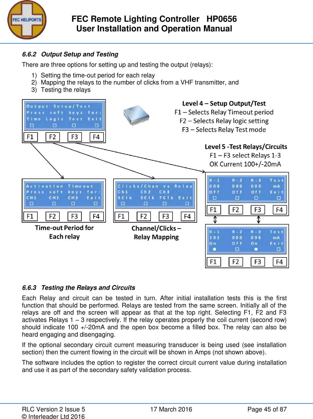
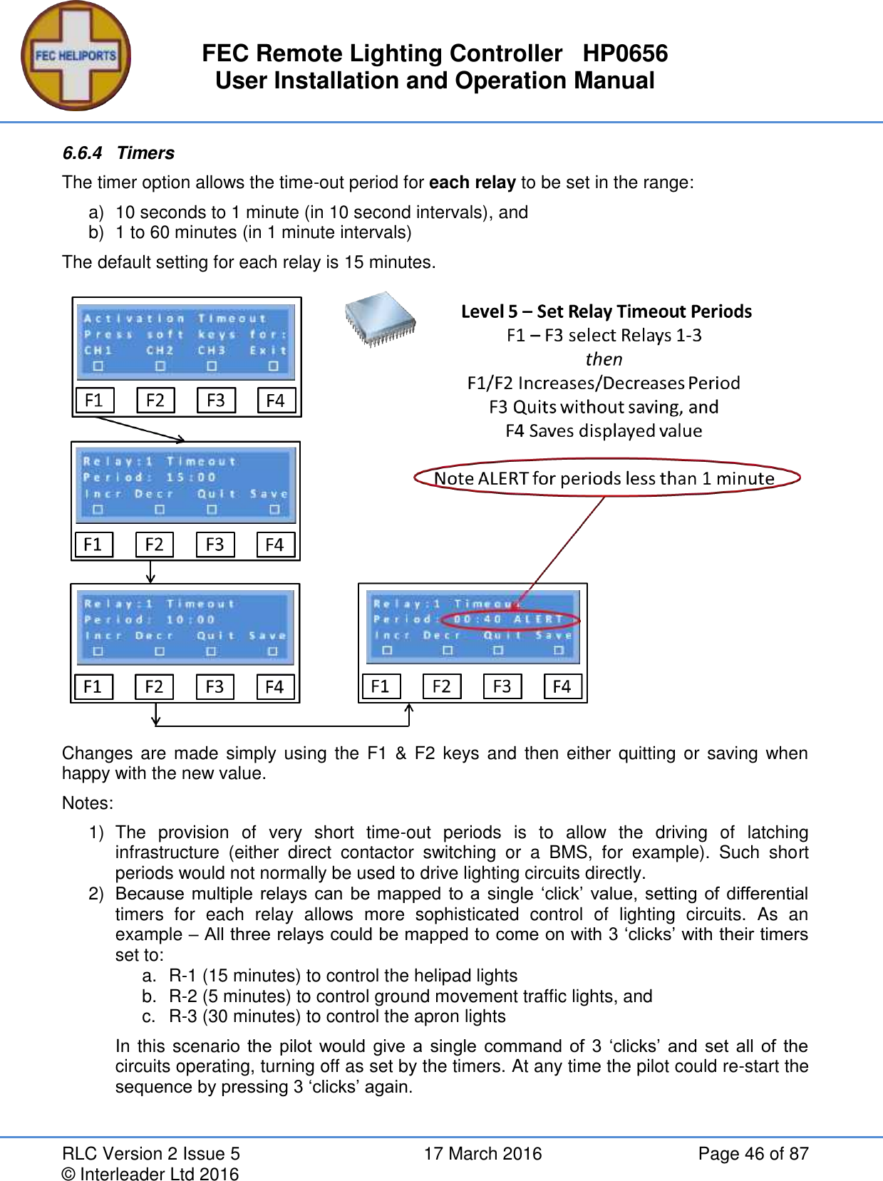
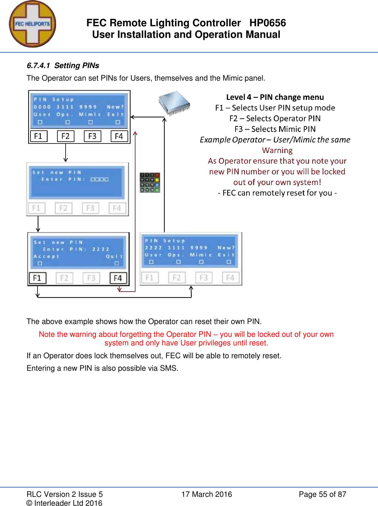
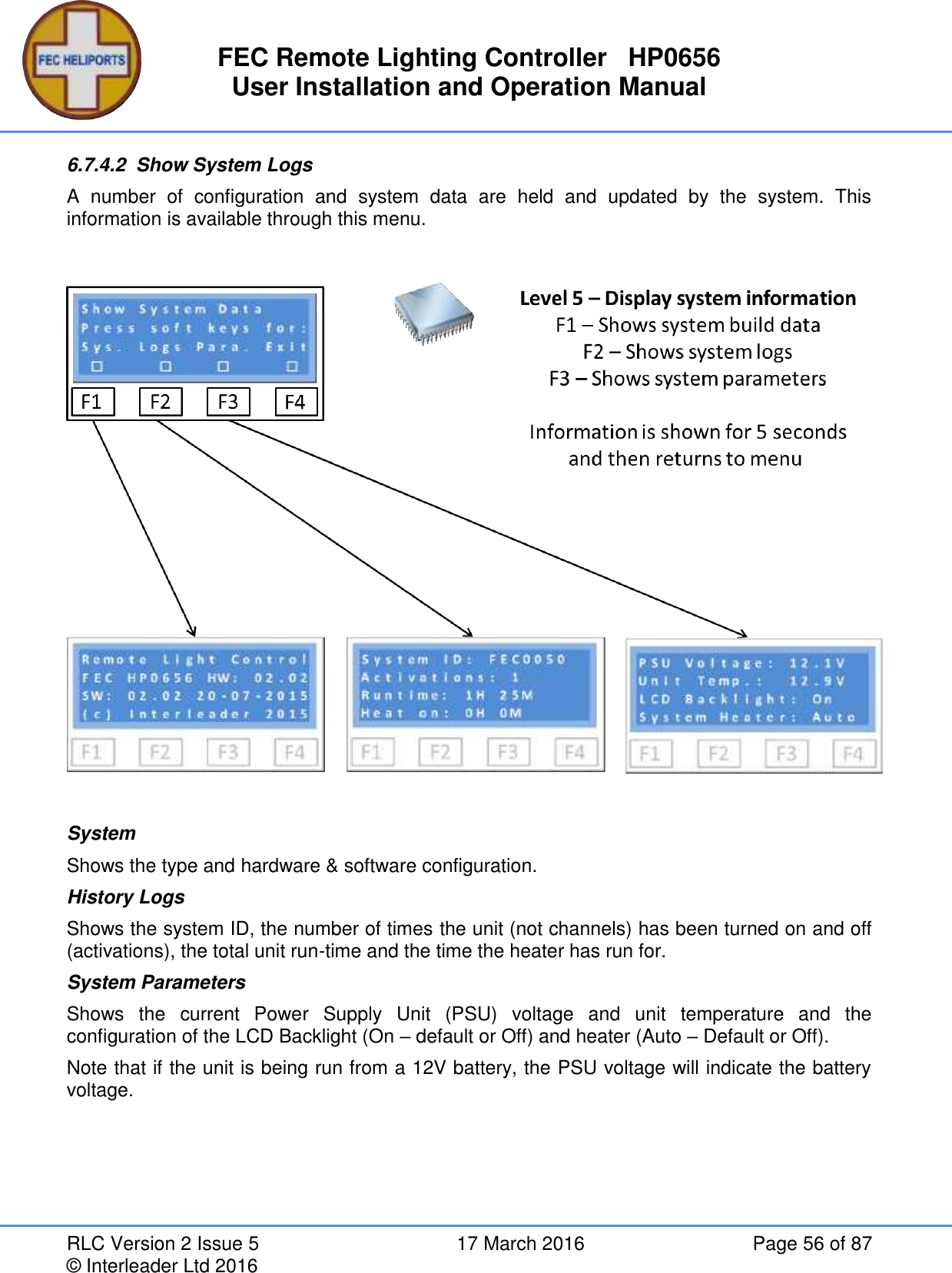
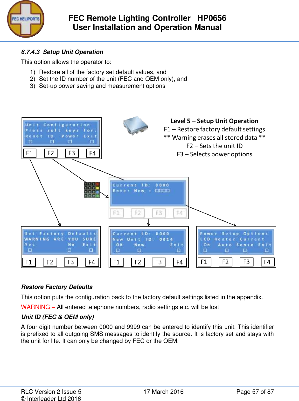
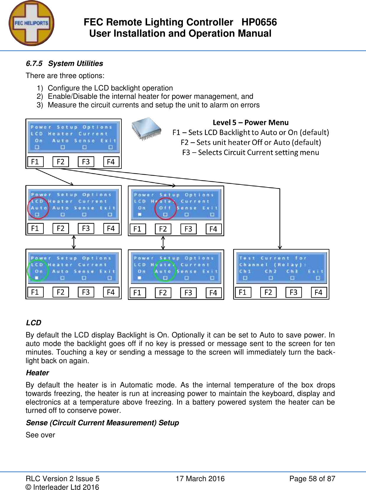
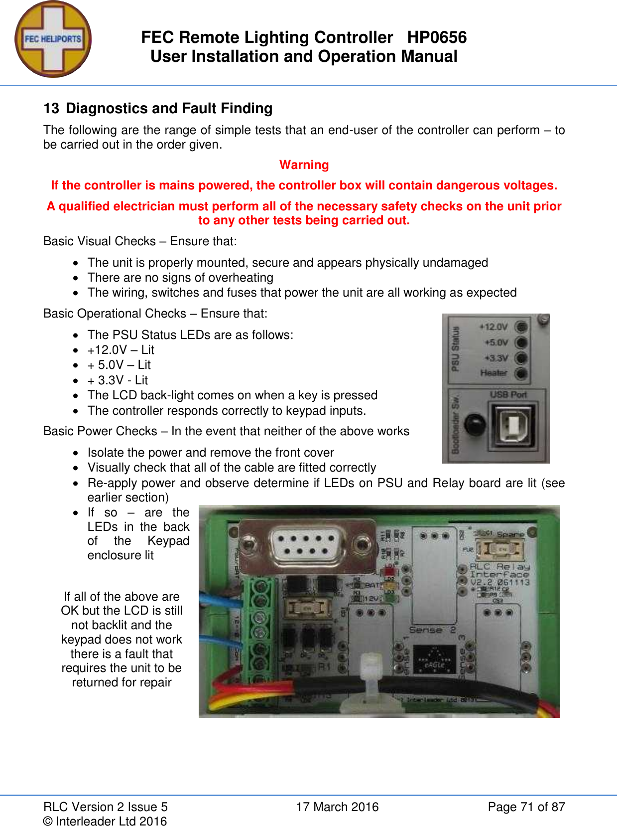
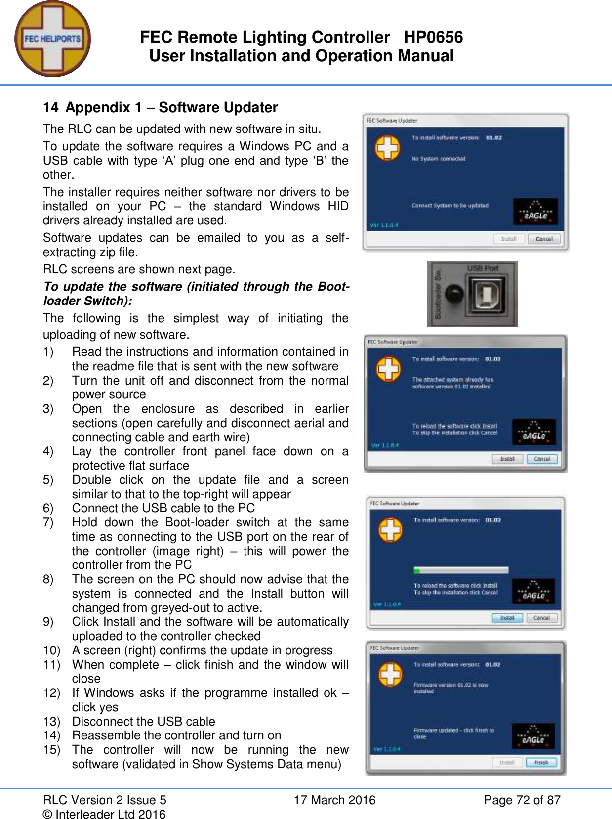
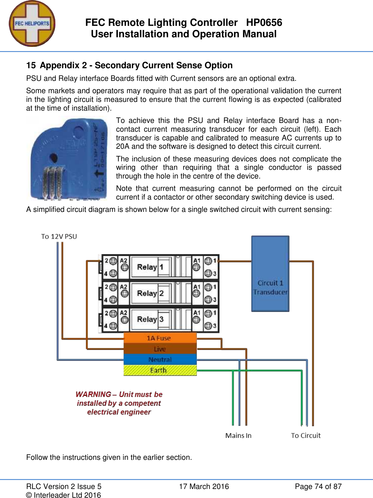
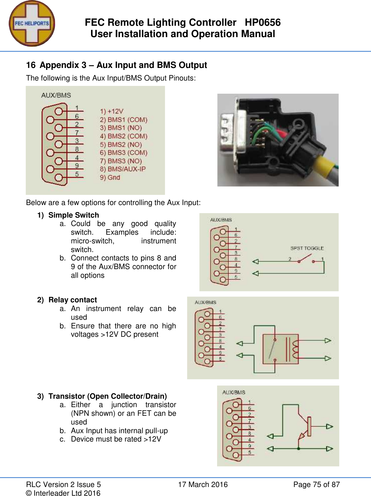
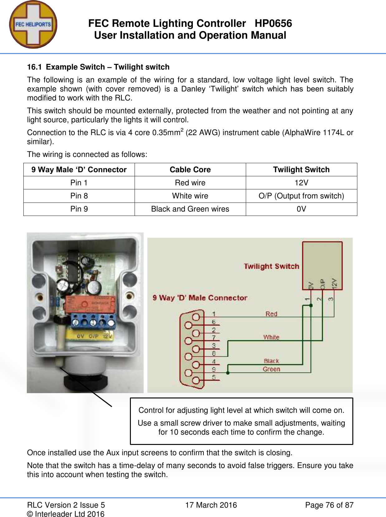
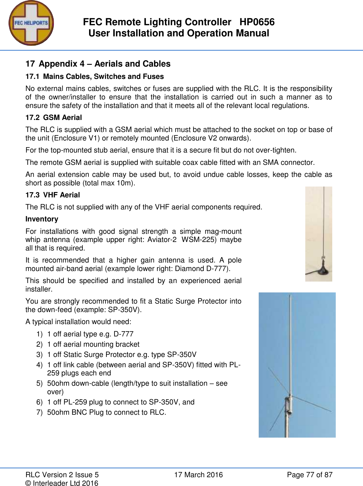
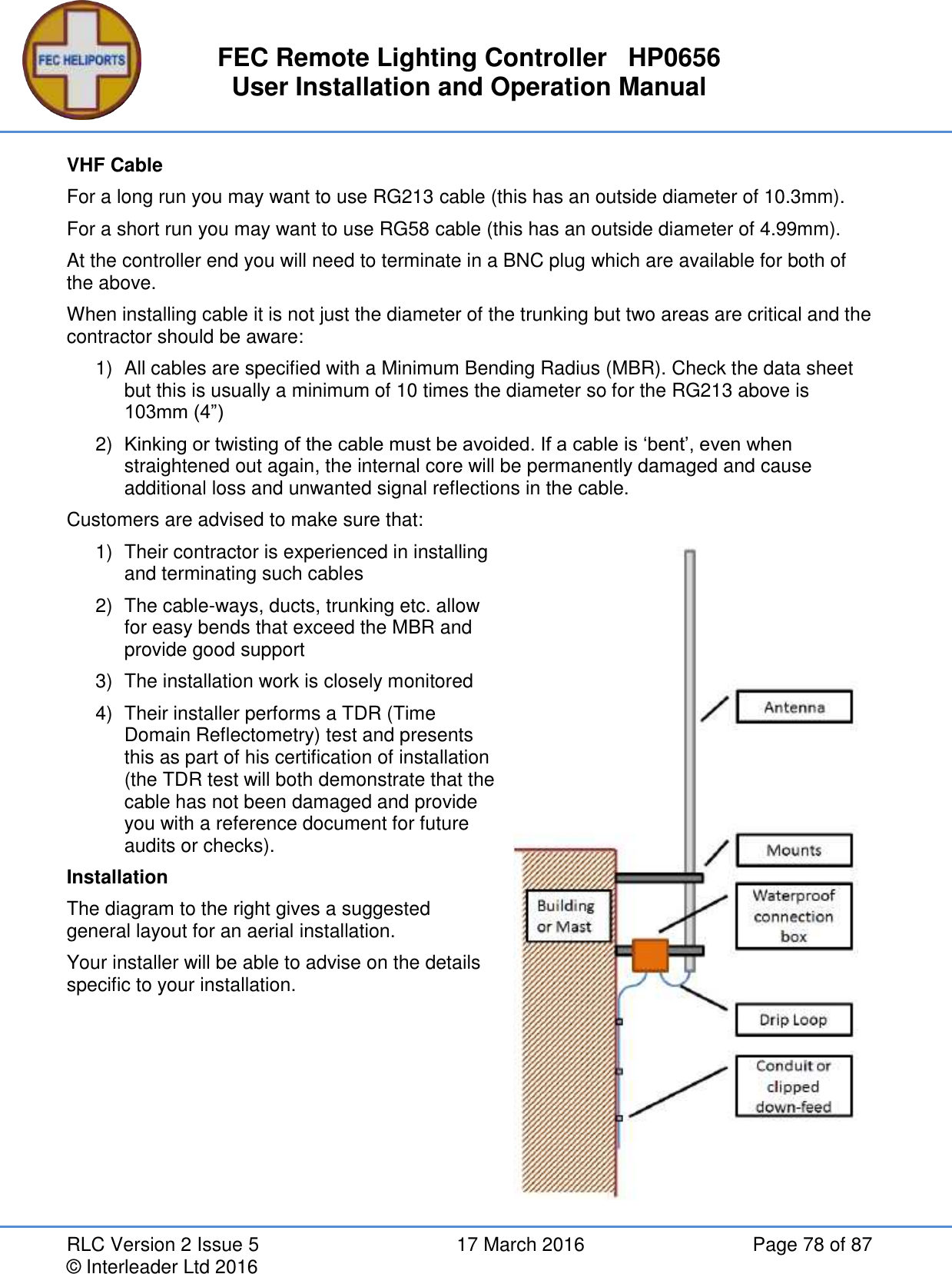
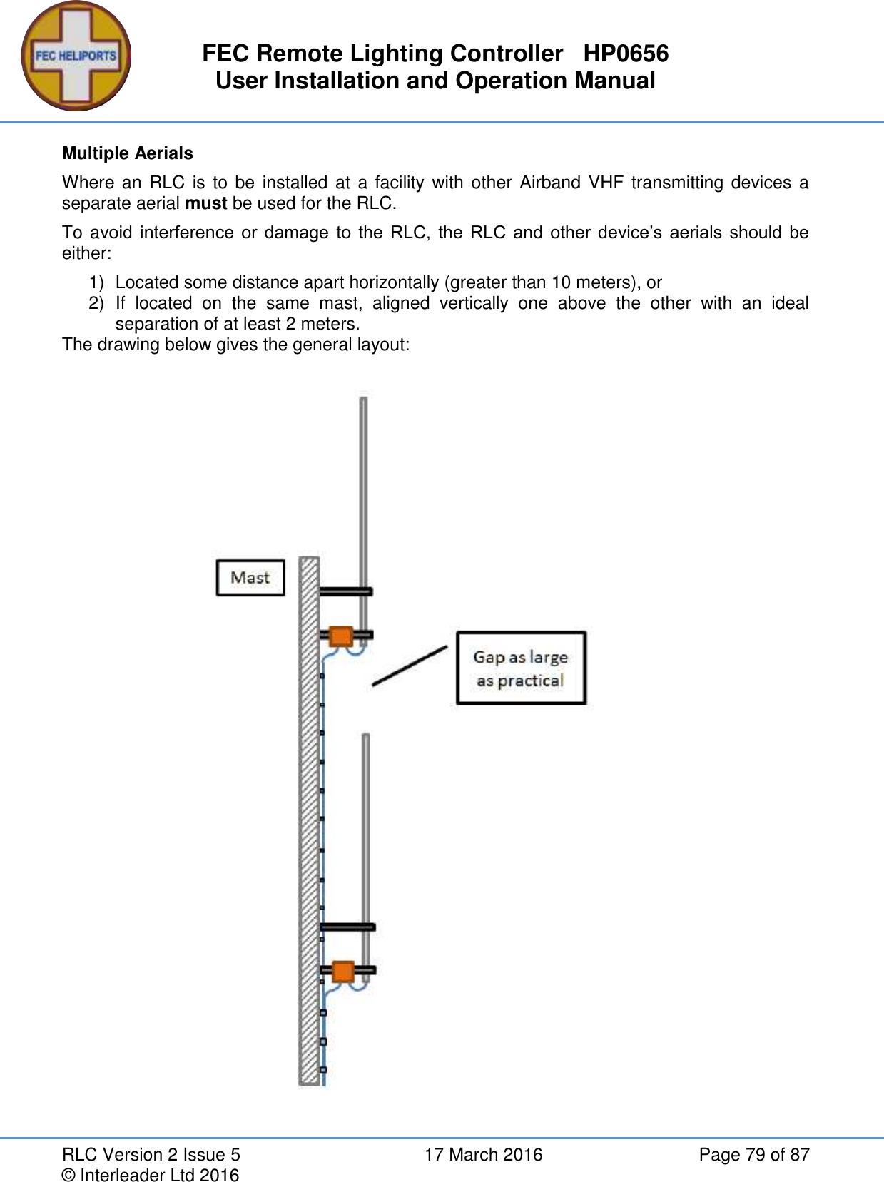
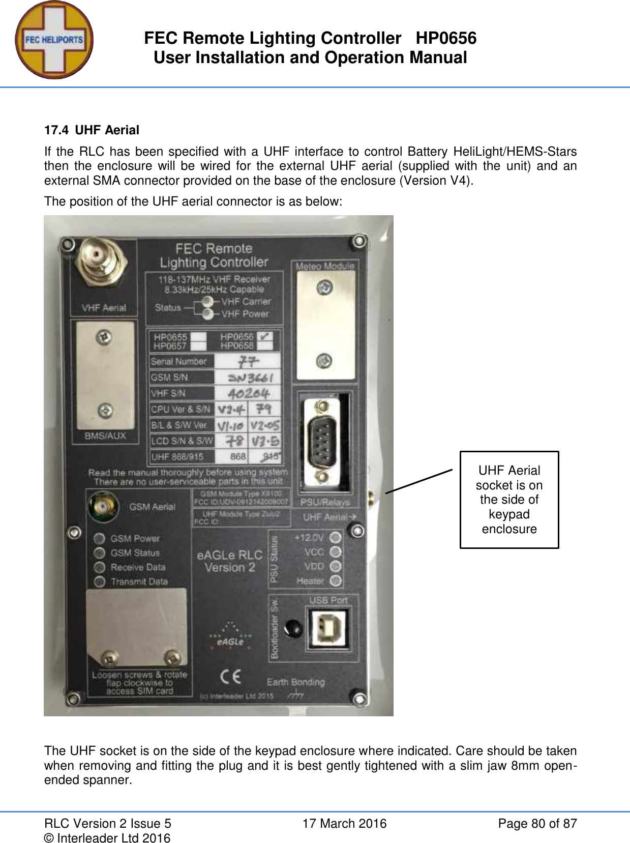
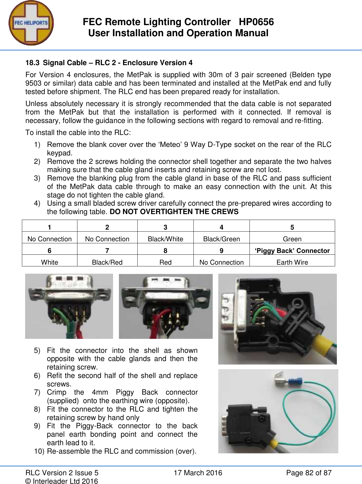
FEC Heliports Worldwide HP0656-7-8-Z9 FEC Remote Lighting Controller V2 User Manual Users manual

FEC Heliports Worldwide Limited FEC Remote Lighting Controller V2 Users manual

Users manual

 Powered by eAGLe Light Engines     ™ Interleader Limited  Remote Lighting Controller FEC Type: HP0656/7/8 User Manual – Specification - Diagnostics   RLC Version 2 Issue: 5            17th March 2016 Note that this manual relates to Hardware V2.4 and Software V2.05 onwards
FEC Remote Lighting Controller   HP0656 User Installation and Operation Manual RLC Version 2 Issue 5  17 March 2016  Page 2 of 87 © Interleader Ltd 2016 Table of Contents 1 Compliance Statements ...................................................................................................... 6 2 Overview ............................................................................................................................. 7 2.1 Key Features ................................................................................................................ 7 2.2 Part Numbers ................................................................................................................ 7 3 Architecture of Remote Lighting Controller .......................................................................... 8 4 Principles of Operation ........................................................................................................ 9 4.1 Keypad and LCD Display - Overview ............................................................................ 9 4.2 The Main Screen......................................................................................................... 10 4.2.1 Entering Menu Mode ............................................................................................ 10 4.3 General ....................................................................................................................... 11 4.4 Channels ..................................................................................................................... 11 4.5 VHF Operation ............................................................................................................ 11 4.6 Keypad Operation ....................................................................................................... 12 4.7 Keypad Cancel............................................................................................................ 12 4.8 GSM/SMS Operation .................................................................................................. 12 5 Normal Operation .............................................................................................................. 13 5.1 Activation by VHF ....................................................................................................... 13 5.2 Activation by Keypad .................................................................................................. 14 5.3 Activation by Auxiliary Input ........................................................................................ 15 5.3.1 Display of Error Conditions ................................................................................... 15 5.3.2 Keypad Cancel by Operator ................................................................................. 16 5.3.3 Keypad Cancel of Auxiliary Input by Operator ...................................................... 16 5.4 Activation by GSM/SMS .............................................................................................. 17 5.4.1 SMS Commands and Response (User) ............................................................... 17 5.4.2 SMS Commands and Response (User) ............................................................... 17 5.4.3 User Example ....................................................................................................... 18 5.5 SMS Commands (All Users) ....................................................................................... 19 5.6 SMS Commands (Operator, FEC and OEM) .............................................................. 20 5.7 SMS Commands (FEC and OEM Only) ...................................................................... 21 5.8 System Response – To User – No Meteorological Pack fitted .................................... 22 5.9 System Response – To User – Meteorological Pack fitted – No Altitude Set ............. 23 5.10 System Response – To User – Meteorological Pack fitted – Altitude Set ................ 24 5.11 Help SMS(s) ............................................................................................................ 25 5.12 System Response – To Others ................................................................................ 25 6 System Setup and Configuration ....................................................................................... 26 6.1 System Access Menu ................................................................................................. 26 6.2 Setup Control Menu .................................................................................................... 27 6.3 Radios Menu ............................................................................................................... 28 6.3.1 Setup VHF Receiver - Basic ................................................................................. 29 6.3.2 Setup VHF Receiver – Advanced ......................................................................... 30 6.3.3 Setup VHF Receiver - Advanced .......................................................................... 31
FEC Remote Lighting Controller   HP0656 User Installation and Operation Manual RLC Version 2 Issue 5  17 March 2016  Page 3 of 87 © Interleader Ltd 2016 6.3.4 VHF Technical – OEM Only ................................................................................. 33 6.4 Setup GSM/SMS Unit ................................................................................................. 34 6.4.1 Set GSM Numbers ............................................................................................... 35 6.5 UHF Transceiver ......................................................................................................... 36 6.5.1 HeliLight Modes .................................................................................................... 36 6.5.2 Default HeliLight Modes ....................................................................................... 37 6.5.3 HEMS-Star Modes ............................................................................................... 37 6.5.4 Remote Switching Controller (RSC) ..................................................................... 37 6.5.5 Commanding the HeliLights/HEMS-Stars Wirelessly ........................................... 38 6.5.6 RLC – Using Channels ......................................................................................... 39 6.5.7 SMS – Direct Control ............................................................................................ 39 6.5.8 Setting up the UHF Transceiver ........................................................................... 40 6.5.9 Testing the RLC – HeliLight/HEMS-Star Link – Test Menu 1 ............................... 41 6.5.10 Testing the RLC – HeliLight/HEMS-Star Link – Test Menu 2 ............................... 42 6.6 Input/Output (BMS) Setup Menu ................................................................................. 43 6.6.1 Auxiliary Input Setup and Testing ......................................................................... 44 6.6.2 Output Setup and Testing..................................................................................... 45 6.6.3 Testing the Relays and Circuits ............................................................................ 45 6.6.4 Timers .................................................................................................................. 46 6.6.5 Relays – Setting which relays respond to inputs .................................................. 47 6.7 Setup Unit Menu ......................................................................................................... 48 6.7.1 Set Real Time Clocks ........................................................................................... 49 6.7.2 Calibrating the System  Real Time Clock ............................................................. 50 6.7.3 Meteo Setup - Units .............................................................................................. 51 6.7.4 Setup Unit............................................................................................................. 54 6.7.5 System Utilities ..................................................................................................... 58 7 Installation ......................................................................................................................... 60 7.1 Locating the Controller ................................................................................................ 60 7.2 Things you will need ................................................................................................... 60 7.3 Preparing for Installation ............................................................................................. 60 7.4 Installing the Base Unit ............................................................................................... 61 7.5 Installing the GSM aerial ............................................................................................. 61 7.6 Electrical Installation ................................................................................................... 62 7.7 Circuit Connectors and Cable Entry (V4 enclosure).................................................... 62 7.8 Relays ......................................................................................................................... 62 7.9 Mains wiring ................................................................................................................ 63 7.10 Basic Wiring Diagram (No secondary current sense) .............................................. 64 7.11 Basic Circuit Testing ................................................................................................ 65 7.11.1 12V DC PSU ........................................................................................................ 65 7.11.2 Manually checking the mains switched circuit ...................................................... 65 7.11.3 Secondary Current Circuit Sensing ...................................................................... 65 7.12 Inserting the SIM ..................................................................................................... 66
FEC Remote Lighting Controller   HP0656 User Installation and Operation Manual RLC Version 2 Issue 5  17 March 2016  Page 4 of 87 © Interleader Ltd 2016 7.13 Final Assembly ........................................................................................................ 66 8 Summary Specification ...................................................................................................... 67 9 UHF Radio Modem Specification ...................................................................................... 68 10 Power Supply Unit Specification ........................................................................................ 69 11 Spare Parts ....................................................................................................................... 69 11.1 Relays ...................................................................................................................... 69 11.2 Other ........................................................................................................................ 69 12 Factory Default Settings .................................................................................................... 70 13 Diagnostics and Fault Finding ........................................................................................... 71 14 Appendix 1 – Software Updater ......................................................................................... 72 15 Appendix 2 - Secondary Current Sense Option ................................................................. 74 16 Appendix 3 – Aux Input and BMS Output .......................................................................... 75 16.1 Example Switch – Twilight switch ............................................................................ 76 17 Appendix 4 – Aerials and Cables ...................................................................................... 77 17.1 Mains Cables, Switches and Fuses ......................................................................... 77 17.2 GSM Aerial .............................................................................................................. 77 17.3 VHF Aerial ............................................................................................................... 77 17.4 UHF Aerial ............................................................................................................... 80 18 Appendix 5 – Mounting and Connection of MetPak ........................................................... 81 18.1 Mounting arrangements ........................................................................................... 81 18.2 Signal Cable ............................................................................................................ 81 18.3 Signal Cable – RLC 2 - Enclosure Version 4 ........................................................... 82 18.4 Commissioning the MetPak ..................................................................................... 83 18.5 MetPak Connections................................................................................................ 84 18.6 The MetPak Connector ............................................................................................ 84 18.7 Connecting the MetPak ........................................................................................... 85 19 Appendix 6 – Mounting Template ...................................................................................... 86
FEC Remote Lighting Controller   HP0656 User Installation and Operation Manual RLC Version 2 Issue 5  17 March 2016  Page 5 of 87 © Interleader Ltd 2016 Document Revision Sheet Version - Issue Date Changes 2 - 1 26th May 2015 New Document for RLC V2 Production model 2 - 2 22nd July 2015 Independent channel time-out and sub 1 minute period Real Time Clock calibration 2 - 3 24th December 2015 Corrected GSM menu options Auxilliary Stop command replaces ‘VHF Disable’ (section 5.6.1) OEM VHF and UHF test routines added  2 - 4 24th February 2016 Statement of Compliance added UHF transceiver specification added Photographs updated to show V2 2 - 5 17th March 2016 UHF Table updated                             Optional Meteorological Pack (Pole Mounted)
FEC Remote Lighting Controller   HP0656 User Installation and Operation Manual RLC Version 2 Issue 5  17 March 2016  Page 6 of 87 © Interleader Ltd 2016 1  Compliance Statements USA FCC Compliance WARNING Changes or modifications to the transmitter not expressly approved by the manufacturer could void the user's authority to operate this RF device. FCC Compliance Statement This device complies with Part 15 of the FCC Rules. Operation is subject to the following two conditions: 1. This device may not cause interference, and 2. This device must accept any interference, including interference that may cause undesired operation of the device. USA-Federal Communications Commission (FCC) This  equipment  has  been  tested  and  found  to  comply  with  the  limits  for  a  Class  B  digital device, pursuant to Part 15 of FCC Rules. These limits are designed to provide reasonable protection against harmful interference in a residential installation. This equipment generates, uses, and can radiate radio frequency energy. If not installed and used in accordance with the instructions, it may cause harmful interference to radio communications. However, there is no ensured  specification  that  interference  will  not  occur  in  a  particular  installation.  If  this equipment  does  cause  harmful  interference  to  radio  or  television  reception,  which  can  be determined by tuning the equipment off and on, the user is encouraged to try and correct the interference by one or more of the following measures: • Reorient or relocate the receiving antenna. • Increase the distance between the equipment and the receiver. •  Connect  the  equipment  to  outlet  on  a  circuit  different  from  that  to  which  the  receiver  is connected. • Consult the dealer or an experienced radio/TV technician for help. Any changes or modifications not expressly approved by the party responsible for compliance could void the user’s authority to operate the equipment.  Europe This device carries the CE marking showing it has been tested and shown to be in compliance with: R&TTE Type Testing EN 300 220-1v2.4.1 & EN 300 220-2v2.4.1 EMC Type Testing EN 301 489-1v1.9.2 & EN 301 489-3v1.6.1
FEC Remote Lighting Controller   HP0656 User Installation and Operation Manual RLC Version 2 Issue 5  17 March 2016  Page 7 of 87 © Interleader Ltd 2016 2  Overview FEC’s Remote Lighting Controller (RLC) is an all new, fully digital design that combines ease of  installation  and  use  with  sophisticated  yet  simple  and  secure  configuration  via  the  IP65 rated keypad and LCD display or via SMS. This manual relates to the RLC Version 2. 2.1  Key Features   Traditional VHF Pilot Controlled Lighting (PLC) configuration   Simple 25kHz/8.33kHz frequency setting through front panel – no fiddly switches   Defined number of presses to activate Channels 1, 2 or 3   Programmable timeout for VHF, keypad and GSM activation   Each channel has fully independent time-out (10 seconds to 60 minutes)   VHF operation can be remotely enabled/disabled for extra security   FCC/EU approved, Integrated tri-band GSM Telemetry Engine for SMS control   Secure PIN code protected SMS commands to monitor and control your installation   Secure SMS status reporting – check out your installation before taking off   Remotely activate Channels 1, 2 or 3 and have the status sent straight back to your mobile   3 Status relay contact outputs for BMS interface   Auxiliary input for switching or BMS control of VHF receiver   Three 20 Amp heavy duty relays in the box – Enables linked peripheral shutdown   Local and remote test and diagnostics integrated into the unit   Very low power consumption – Approx. 3W (idle) and less than 30W max. (including internal winter heater)   Operates from 110-240V AC 50-60Hz or 12V DC (ideal for solar and batteries)   Weather station interface for meteorological information from your helipad  Options  Wireless Battery ‘HeliLight’ control (not in USA) 2.2  Part Numbers Standard Equipment Combined VHF and SMS Unit VHF Only Unit SMS Only Unit HP0656 HP0657 HP0658 Optional Extras Remote/Mimic Panel Meteorological Station Secondary    Circuit  Current Measurement HP0655 HP0659 HPTBC FEC and Interleader Ltd have a policy of continuous product improvement and reserve the right to change specifications of products. See website for latest details.
FEC Remote Lighting Controller   HP0656 User Installation and Operation Manual RLC Version 2 Issue 5  17 March 2016  Page 8 of 87 © Interleader Ltd 2016 3  Architecture of Remote Lighting Controller Effective  operator  or  pilot  control  of  Helipad  Lighting  is  critical  to  the  safe  operation  of  an installation and traditional Radio Pilot Controlled Lighting (PCL) solutions using the VHF radio is a tried and trusted method. Now there is a new way to control your lighting and peripheral circuits using FEC’s new   RLC which  integrates  both  traditional  VHF  PCL  and  adds  SMS  control  and  monitoring  with  the option  of  automatic  weather  reporting  (wind  speed/direction,  temperature,  dew  point  and pressure) right from your helipad. FEC’s RLC sits at the heart of a monitoring and control capability bringing together for the first time remote lighting control, helipad weather and system reporting. The architecture can be used simply to control lights or, with additional meterological sensors, to provide richer monitoring and reporting both by helipad operators and other agencies. All of these features are under the full and secure control of the owner/operator and are the basic building blocks on which future FEC developments will be built. RLC Version adds direct BMS input and 3 outputs.   NB – Battery/Wireless (868MHz UHF) UK/EU/ROW   -   (915MHz UHF) USA
FEC Remote Lighting Controller   HP0656 User Installation and Operation Manual RLC Version 2 Issue 5  17 March 2016  Page 9 of 87 © Interleader Ltd 2016 4  Principles of Operation 4.1  Keypad and LCD Display - Overview The FEC RLC is fully configurable via the front panel keypad and screen. All setup, test and monitoring of the controller is carried out via the front panel keypad and LCD display (many commands also possible remotely via SMS – see later section). There are no controls inside the case.  The menus are arranged in an hierarchical structure with a consistent presentation format and key operation. Extensive use is made of the 4 ‘Function Keys’ above the main 16 key keypad and, in conjunction with changing legends on the screen, intuitively guide the user through the various steps.     The key features of the interface are shown left.            In the example to the left:  The 1st line indicates VHF Radio on 122.800MHz. The 2nd line indicates GSM Radio on. The 3rd line confirms the function of each key. The 4th line represents the Function Keys.  Note that in some menus the boxes in the 4th line also give the current status of that function. For example, in the Test Output (O/P) test mode, the relays can be set and unset individually. As they change state the squares change from open to solid to indicate the active state. Note that in some menus more information is provided and hence the exact layout above not followed. The approach is the same and where there are differences instructions provided. F4,  usually  marked  ‘Exit’,  returns  to  the  previous  level  in  the  menu  and  in  many  screens accepts the conditions set in that menu. If Marked ‘Quit’ then that screen is discarded before return. Repeatedly pressing F4 will bring you back to the main menu.   LCD Screen Common Layout Line 1 indicates the menu level Line 2 provides instruction Line 3 Indicates the ‘Function Keys’ function Line 4 identifies the keys and their status Function Keys 1-4 (left to Right) Data Entry Keypad
FEC Remote Lighting Controller   HP0656 User Installation and Operation Manual RLC Version 2 Issue 5  17 March 2016  Page 10 of 87 © Interleader Ltd 2016 4.2  The Main Screen The top menu is not really a menu at all but rather the main status display page with two main options: 1) select the menu or 2) directly activate a Channel. By default the screen remains lit all of the time. To save power (particularly useful in battery powered installations) the LCD screen back-light can be set to ‘Auto’ in which case it goes out 30  seconds  after  the  last  key  was pressed or the  screen  was refreshed. To  re-activate the backlight,  simply  momentarily  touch  any  key  and  the  screen  will  light  up  for  another  30 seconds. During an Active Period (when the controller has been commanded to turn on the lights) the screen is regularly updated with a down-count to the end of the Active Period and so the screen remains on. See section on system setup. The screen provides all of the essential information to show the status of the system.  The screen on the left is showing the following:  Line  1: The VHF  receiver is ON  – shown by both the filled box  and  the  word  ‘On’  and  the operating frequency is shown – in this example a US UNICOM frequency. Line 2: The GSM receiver is ON - shown by both the filled box and the word ‘On’. Line 3: Is the legend and functional description of the function keys Line 4: Indicates the status of the channels. In this example, none are active (open boxes) and the Menu is available via the Function Key 4 below it. In the  screen on the right a Pilot has activated the system via VHF  Channel 1 (Relay 1) is active and the system menu is unavailable until the predefined time-out period. The timeout period is shown, down counting every second. 4.2.1  Entering Menu Mode  To enter the Menu mode, simply press the function key (F4).  You will be taken immediately to the PIN challenge screen (above) to enter your security PIN. Note that the representation above is used consistently throughout the manual. The FEC RLC adopts  a  set  of  simple  but  key  principles  in  its  mode  of  operation.  These  principles,  which guide how the system works, are outlined below. V H F :nO n 1 2 2 . 8 0 0MH zG SM:nO nC H 1 C H 2 C H 3Me n u  nA c c e s s   V i a :   V H F          L a s t   o n   B y :   P i l o tC H 1 C H 2 C H 30 0 : 1 9   O N
FEC Remote Lighting Controller   HP0656 User Installation and Operation Manual RLC Version 2 Issue 5  17 March 2016  Page 11 of 87 © Interleader Ltd 2016 4.3  General The  controller  is  designed  to  ‘fail  safe’.  For  example  –  If  power  is  lost  at  any  time,  on resumption of power, the controller will re-start under the conditions it was in at the time of power failure: If the VHF receiver had previously been set to ‘inactive’ that is the state it will restart in. There are a number of ‘Types’ of users of the system: User – This is generally the pilot who has been given permission to use the system. Operator – This is the owner or operator of the facility. Agency – A third party who the operator wishes to be informed of operational activity. Mimic – A designated mimic panel used to remotely control and report RLC activity  FEC – FEC have defined access to certain options (e.g. reset the Operators PIN). OEM – The Original Equipment Manufacturer has defined access to perform diagnostic and support options. The options available to FEC and OEM are explicitly defined as part of the supply agreement. 4.4  Channels The RLC uses the concept of ‘Channels’ to control which of the control relays are activated by VHF commands. The default settings are as follows:  Keypad Action VHF Action Default Relay Activated Soft Key # 1 Pressed 3 ‘clicks’ Relay 1 activated Soft Key # 2 Pressed 5 ‘clicks’ Relay 2 activated Soft Key # 3 Pressed 7 ‘clicks’ Relay 3 activated Note that any combination of relays can be activated instead of the defaults (see later section). 4.5  VHF Operation If  VHF  is  ‘Active’  then  the  controller  will  be  activated  if  3,  5  or  7  presses  of  the  aircraft microphone switch are made in a 5 second period by an approaching pilot on frequency. This will turn on whichever relay(s) have been assigned to channels 1, 2 or 3 respectively for the periods previously set by the operator (default 15 minutes) for each relay.  There  is  no  restriction  as  to  who  can  use  the  VHF part  of  the controller.  If  it is  active  and someone is on frequency they can operate it. During this period the ‘Menu’  option is not available but additional channels can be activated by pressing the microphone switch again. Each time a channel is set the timeout period for that relay is reset.
FEC Remote Lighting Controller   HP0656 User Installation and Operation Manual RLC Version 2 Issue 5  17 March 2016  Page 12 of 87 © Interleader Ltd 2016 4.6  Keypad Operation If the controller is at the main menu level (waiting for input) or a channel(s) is already active, pressing function button 1, 2 or 3 will invoke the PIN password challenge which, if successful, will then turn on Channels 1, 2 or 3. Only a User or Operator with the correct password can activate the system in this way. During this period the ‘Menu’  option is not available but additional channels can be activated by repeating the above action. Each time a channel is set the timeout period is reset. 4.7  Keypad Cancel If any channel has been set On (via VHF, GSM or keypad) input the Operator can terminate all of the timeout periods. To do this: 1)  Press the <CAN> key 2)  Enter Operator PIN The timeout loops will be aborted and the system will return to the main menu. Any other inputs or the wrong PIN will be ignored and the timeouts continue.  4.8  GSM/SMS Operation Operational activity is limited to the User and Operator only as follows: Action User Operator Comment Obtain Status   All service requests require a correct PIN Turn Channel(s) ON    Turn Channel(s) OFF  * *Note a User can turn a channel OFF only if they previously turned it ON An Operator can always turn channels OFF irrespective of who turned it ON Turn VHF Radio On/Off    Set  User,  Operator  and Mimic PINS    Obtain Meteorological data   Only with optional Meteorological package Confirm Meteorological Units    Change Meteorological Units   e.g. wind speed from knots to mph Obtain Help Menu   User receives 1 text of help, the Operator 2 covering the extended commands available
FEC Remote Lighting Controller   HP0656 User Installation and Operation Manual RLC Version 2 Issue 5  17 March 2016  Page 13 of 87 © Interleader Ltd 2016 5  Normal Operation 5.1  Activation by VHF When operating normally the screen will typically show the following (left): The screen provides all of the essential information to show the status of the system.   In this case Indicating that both VHF and GSM are ON but that no channel is active. As soon as a VHF signal is detected on frequency the screen will immediately change to that on the right indicating 1 Carrier Detect (CD) activity.  During  a  5  second  period  (a  de-facto  standard  for  Pilot  Controlled  Lighting)  the  system  is counting ‘clicks’ from the pilot. The number of clicks (CD) received in the 5 second period is displayed as shown above and at the end of that period the following occurs: Clicks Action Comment 1, 2, 4, 6 or 8 or more clicks No action taken Return to standby One click will be detected any time a pilot or  ground  station  on  frequency  presses their push-to-talk microphone button. 3 Activate channel 1 See screen below 5 Activate channel 2  7 Activate channel 3  If no action is taken, the screen will return to that shown at the top of the page (left), or if a channel is activated, for example to one, shown below.  The above shows that Chanel 1 (Relay 1) is active (ON) and that the system is timing down. The time-out period is 0 minutes 19 seconds. At the end of this period the channel will be de-activated. At  any  time  the  pilot  can  re-activate  the  same  channel  or  activate  a  different  channel  by pressing  their  PTT  again  the  required  number  of  clicks.  The  channels  requested  will  be activated and its time-out period begin counting down again.   A c c e s s   V i a :   V H F          L a s t   o n   B y :   P i l o tC H 1 C H 2 C H 30 0 : 1 9   O NV H F :nO n 1 2 2 . 8 0 0MH zG SM:nO nC H 1 C H 2 C H 3Me n u  nV H F :nO n 1 2 2 . 8 0 0MH zG SM:nO n C D # : 1C H 1 C H 2 C H 3Me n u  n
FEC Remote Lighting Controller   HP0656 User Installation and Operation Manual RLC Version 2 Issue 5  17 March 2016  Page 14 of 87 © Interleader Ltd 2016 5.2  Activation by Keypad At any time (other than during menu operations) touching any of the three ‘channel’ keys (F1 – F3) will immediately challenge for a PIN number. The system will accept either a valid User or Operator  PIN.  If  a  correct  PIN  number  is  given,  the  system  will  then  activate  the  selected channel (relay)). This method of activation is a secure and convenient way of activating the lights if the helipad is manned.  Note that even if a channel has already been activated by a different user/route (as above), it is possible to re-activate the same channel (to extend the timeout period) or activate a different channel. In the example below, Channel 1 (Relay 1) was already active and then the Operator has activated Channel 2 (Relay 2) and started its time-out.   The screen will display the status of the relays and also confirm that the latest activation is via the keypad and by either a User or the Operator (a function of the PIN code used). The system will down-count for the time-out periods just as it would for a VHF input. Note that if the RLC is fitted with both VHF and GSM receivers and the ‘Operator’ number has been entered, the Operator will receive an SMS notification when a channel is activated via the keypad  as  well  as  VHF  and  GSM.  This  allows  the  Operator  to  maintain  awareness  of  all channel activations however triggered. With the exception of Keypad Cancel (see later section), once activated the Menu option is unavailable and any key presses on the keypad are ignored (other than F1 - F4 and <CAN>). This is a safety feature to ensure no compromise of the operation once initiated.   A c c e s s   V i a :   K e y p a d    L a s t   o n   B y :   O p e r a t o rC H 1 C H 2 C H 30 5 : 5 3 0 3 : 3 9 O N
FEC Remote Lighting Controller   HP0656 User Installation and Operation Manual RLC Version 2 Issue 5  17 March 2016  Page 15 of 87 © Interleader Ltd 2016 5.3  Activation by Auxiliary Input The BMS/Aux Input  has an  input detect capability that can be configured to turn 1 or more relays on without timeout for the period that the input is active. This feature is useful where an external switch is required to over-ride other commands and turn a circuit(s) on and leave it on. Details of how to set this feature up are included in sections 5.6 and 5.6.1. Examples of switching inputs are shown in the appendix.  Once enabled and then activated the screen will appear as follows:  In this example  Channel 2 (relay 2) had been previously activated. This  is indicated by the solid square showing below the relay designation. Since  being activated by  the  auxiliary input,  Channel 1  (relay 1)  has  been  activated  by the Operator via the keypad and the timer is counting down. All the time that the auxiliary input is active, a similar screen to that above will remain. Other channels may be activated and will operate normally.  5.3.1  Display of Error Conditions If the system determines that there is an error in activating a circuit this will be communicated three ways: a)  The LCD screen will show which channel is in error (see screen below)  b)  The relevant BMS output will be made, and c)  The  Operator  will  receive  an  SMS  confirming  this  (if  the  Operator  number  has  been entered into the system)  In the above example, Channel 3 is in error.   A c c e s s   V i a :   K e y p a d    L a s t   o n   B y :   O p e r a t o rC H 1 C H 2 C H 31 0 : 3 3nO NA c c e s s   V i a :   K e y p a d    L a s t   o n   B y :   O p e r a t o rC H 1 C H 2 C H 30 9 : 1 3nE r r o r O N
FEC Remote Lighting Controller   HP0656 User Installation and Operation Manual RLC Version 2 Issue 5  17 March 2016  Page 16 of 87 © Interleader Ltd 2016 5.3.2  Keypad Cancel by Operator At any time when the channel(s) are active the Operator can terminate the timeout periods/turn the lights Off. To do this: 1)  Press the <CAN> key 2)  Enter the valid Operator PIN  The  timeout  loops  will  be  aborted  and  the  system  will  return  to  the  main  menu.  Any  other inputs or the wrong PIN will be ignored and the timeout continue. Note that if the RLC is fitted with both VHF and GSM receivers and the ‘Operator’ number has been entered,  the Operator will receive an SMS notification when a channel is de-activated via the keypad as well as GSM. Note that if a User has activated a channel(s) (either by keypad or SMS) they will not receive confirmation that the channel(s) have been de-activated. If used with a Mimic system, the Mimic will always receive notification of de-activation. If  an  Agency  number  has  been  entered, The  Agency  will  always  receive  notification  of  de-activation. 5.3.3  Keypad Cancel of Auxiliary Input by Operator If the Auxiliary input is being used to control channel (relays), as in the example above, then after the Operator PIN challenge above the system will ask if the Auxiliary switching is to be turned off. If this is the case, the following screen will appear:  If the Operator selects Yes then the following occurs: 1)  The Auxiliary Input is turned off 2)  The Auxiliary Relay mapping is cleared, and 3)  All channels (relays) are cleared If the Operator selects No then the following occurs: 1)  Any  channels  (relays)  not  controlled  by  the  Auxiliary  Input  (Channel  1  in  the  above example) are turned off. 2)  The channels (relays) controlled by the Auxiliary Input are left unchanged (on).    P I N S e c u r i t y C h e c kE n t e r P I N :C H 1 C H 2 C H 31 0 : 3 3nO N#   O p e r a t o r   C a n c e l     #T u r n   A u x .   I n p u t   O f f ?Y e s N o 
FEC Remote Lighting Controller   HP0656 User Installation and Operation Manual RLC Version 2 Issue 5  17 March 2016  Page 17 of 87 © Interleader Ltd 2016 5.4  Activation by GSM/SMS If a channel is activated by an SMS (see later section for format) then the following screen will appear.   Note that additional SMS may be sent to the unit so that, for example, if channel 3  (relay 3) has already been turned on (as above), channels 1 and/or 2 can then be also turned on. Note that each SMS can turn 1, 2 or 3 channels on or off at one time. If a User has activated the channel (with the correct User PIN) then the User can turn it off again.  To  avoid  a  situation  where  a  User  has  finished  with  the  lights  but  not  turned  them  off,  the Operator can also turn the lights off even though it was a User who turned them on. The Owner must be absolutely sure that the situation is safe for the lights to be turned off. 5.4.1  SMS Commands and Response (User) As a User with the correct PIN you can: 1)  Check the status of the system 2)  Check meteorological units set 3)  Obtain meteorological data (if optional meteorological package is fitted) 4)  Turn channels On 5)  Turn channels Off 6)  Obtain a User help menu 5.4.2  SMS Commands and Response (User) As an Operator with the correct PIN you can: 1)  Perform the User functions above 2)  Turn the VHF Radio On/Off 3)  Set new User, Operator and Mimic PINs 4)  Change the reporting units of the Meteorological unit 5)  Obtain both the User and Operator help menus   A c c e s s   V i a :   G SM         L a s t   o n   B y :   U s e r        C H 1 C H 2 C H 3  0 5 : 5 3 O N
FEC Remote Lighting Controller   HP0656 User Installation and Operation Manual RLC Version 2 Issue 5  17 March 2016  Page 18 of 87 © Interleader Ltd 2016 5.4.3  User Example A User of the system has been given the GSM (cell phone) number of the controller and the current PIN (in this case the default User PIN is 0000) and wishes to turn on channel 1. Example 1 – Single Channel On and Off To turn the lights ON the User sends the following SMS to the Controller: U0000C1A Note all commands start with the user type, in this case ‘U’ for User – in conjunction with the PIN this forms part of the security validation. Next the PIN number is sent ‘0000’, followed by the required action. In our example we have asked for Channel 1 to be made Active (turned ON). Note that lower case can be used for the C and the A and that all commands follow the same format (next pages). If the SMS is correct (right syntax, correct PIN), the controller will carry out that task. Turning the channel off again is: U0000c1n The User has asked for channel 1 to be made negative (turned OFF). Example 2 – Multiple Channel On and Off To turn the lights ON the User sends the following SMS to the Controller: U0000C231A The User and PIN are as above In this example we have asked for Channels 1, 2 and 3 to be made Active (turned ON). Turning the channel off again is: U0000c12n The User has asked for channels 1 and 2 to be made negative (turned OFF). Note that in the above example: 1)  The channel numbers do not have to be entered in order, and 2)  A different number of channels can be turned on and off. In the example above channel 3 would remain on until the end of the timeout period or it was turned off individually. See section 7.10 for Help Menus.
FEC Remote Lighting Controller   HP0656 User Installation and Operation Manual RLC Version 2 Issue 5  17 March 2016  Page 19 of 87 © Interleader Ltd 2016 5.5  SMS Commands (All Users)
FEC Remote Lighting Controller   HP0656 User Installation and Operation Manual RLC Version 2 Issue 5  17 March 2016  Page 20 of 87 © Interleader Ltd 2016 5.6  SMS Commands (Operator, FEC and OEM)
FEC Remote Lighting Controller   HP0656 User Installation and Operation Manual RLC Version 2 Issue 5  17 March 2016  Page 21 of 87 © Interleader Ltd 2016 5.7  SMS Commands (FEC and OEM Only)
FEC Remote Lighting Controller   HP0656 User Installation and Operation Manual RLC Version 2 Issue 5  17 March 2016  Page 22 of 87 © Interleader Ltd 2016 5.8  System Response – To User – No Meteorological Pack fitted The  controller  will  respond  to  the  caller  (either  User  or  Operator)  with  confirmation  of  the system status. The standard response is shown in the screen shot of an iPhone below:      Command sent by User Controller ID VHF Radio Active 122.8MHz Confirmation: Channel 1 Timeout: 15 Minutes Confirmation: Channel 2 Off No Meteorological Pack fitted Time/Date stamp of transmission in international format Confirmation: Channel 3 Off Event Number
FEC Remote Lighting Controller   HP0656 User Installation and Operation Manual RLC Version 2 Issue 5  17 March 2016  Page 23 of 87 © Interleader Ltd 2016 5.9  System Response – To User – Meteorological Pack fitted – No Altitude Set  The standard response is shown in the screen shot of an iPhone below if a MetPak is fitted but altitude NOT set. If  the meteorological station altitude is  not  set, no  pressure  information is sent.       Controller ID VHF Radio Active 122.8MHz Confirmation: Channel 1 On Timeout: 14 Mins. 59 Secs. Confirmation: Channel 2 Off Meteorological reporting option fitted – information to follow Time/Date stamp of transmission in international format Confirmation: Channel 3 Off Controller/Meteo ID Caution Wind Direction and Speed Barometric Pressure not sent as Meteo Altitude not set Temperature Dewpoint Relative Humidity Time/Date Stamp Event Number Caution: Meteo altitude not set
FEC Remote Lighting Controller   HP0656 User Installation and Operation Manual RLC Version 2 Issue 5  17 March 2016  Page 24 of 87 © Interleader Ltd 2016 5.10  System Response – To User – Meteorological Pack fitted – Altitude Set  The standard response is shown in the screen shot of an iPhone below if a MetPak is fitted and altitude is set. Pressure information is sent if the meteorological station altitude is set. Note that in this example Channel 2 (relay 2) has been set permanently On via the Auxiliary Input. This is indicated by displaying On and no timeout period.      Controller ID VHF Radio Active 122.8MHz Confirmation: Channel 1 On Timeout: 15 Minutes Confirmation: Channel 2 On Timeout: None – set by Aux. In Meteorological reporting option fitted – information to follow Time/Date stamp of transmission in international format Confirmation: Channel 3 Off Controller/Meteo ID Caution Wind Direction and Speed Barometric Pressure sent as Meteo Altitude set Temperature Dewpoint Relative Humidity Time/Date Stamp Event Number Meteo altitude set
FEC Remote Lighting Controller   HP0656 User Installation and Operation Manual RLC Version 2 Issue 5  17 March 2016  Page 25 of 87 © Interleader Ltd 2016 The  SMS  is  just as readable on older handsets  but  may require scrolling  to  read all of the message. If the controller had failed to make the channel active then in this example it would read: C1 Inactive. If  the controller  has  been  configured  to measure  the  channel  current  and  validate that it  is within limits then a message to this effect will be appended to the Ch(n) status line. 5.11  Help SMS(s) Users, the Operator, FEC and the OEM can all request help screen(s) which give a summary of the commands available via SMS. The request is User-Type PIN ? e.g. U0000? Users – Receive Help Menu 1 with the commands available to them.  Operators – Receive Help Menus 1 and 2 - the extended commands available to Operators. FEC & OEM – Receive Help Menus 1, 2 and 3 - with the reserved commands available to FEC and OEM. The screen shots below are of the three Help Menus.           RLC Help Menu 1  RLC Help Menu 2  RLC Help Menu 3   5.12  System Response – To Others Every  time  that  the  controller  changes  state  or  makes  a  channel  active  or  inactive,  at  the Operators option the above message will also be sent to any or all of the following: 1)  Operator – Receives all state changes to the controller 2)  Agency – An Operator agreed number that will receive operational changes only 3)  Mimic – The designated Mimic panel Examples: 1)  If  the  Operator  turns  the  VHF  radio  receiver  off,  only  the  Operator  will  receive confirmation of that. If a User Turns the lights on via SMS, the User, Operator, Agency and Mimic numbers will all be sent the appropriate system response.
FEC Remote Lighting Controller   HP0656 User Installation and Operation Manual RLC Version 2 Issue 5  17 March 2016  Page 26 of 87 © Interleader Ltd 2016 6  System Setup and Configuration 6.1  System Access Menu Pressing ‘Menu’ on the main menu first brings up a PIN challenge menu to determine which ‘type’ of user is accessing the system since each can perform different functions: There are five types of ‘User’ defined in the system: 1)  User – A person granted permission to perform certain commands. 2)  Ops. – The Owner/Operator of the facility. 3)  Mimic – The remote control/monitoring panel (not entered via keypad) 4)  FEC – Technical staff from FEC. 5)  OEM – The Original Equipment Manufacturer. Each type of user has a PIN access code and can perform a variety of configuration and other tasks on the system. Using the  numeric PIN  code,  enter  the  4  number  PIN  code.  As each  number  is pressed  it replaces the relevant box until four numbers are entered. NB – As an additional security measure, if numbers are not entered within 5 seconds of each other, the screen times out and returns to the main menu. Also if the wrong code is given this is advised and a return made to the main programme.  Warning Once the Menu Mode is selected, the system no longer monitors the VHF or GSM receivers and will not respond to remote commands. All setups should be performed when it is known that no movements requiring the lighting controller are required
FEC Remote Lighting Controller   HP0656 User Installation and Operation Manual RLC Version 2 Issue 5  17 March 2016  Page 27 of 87 © Interleader Ltd 2016 6.2  Setup Control Menu Once the correct PIN has been entered the Setup menu is entered.   There are three main setup areas: Radios, Input/Output (Relays) and System. In the following sections we will go through each of these areas in turn.   To aid navigation within this document, the radio, cell phone, HeliLight and chip images are used to represent the VHF Radio, GSM Radio, UHF Radio and System respectively: VHF Radio:                 UHF Radio: (Battery HeliLight Controller)  GSM Radio:                System:
FEC Remote Lighting Controller   HP0656 User Installation and Operation Manual RLC Version 2 Issue 5  17 March 2016  Page 28 of 87 © Interleader Ltd 2016 6.3  Radios Menu There can be up to 3 radios in the system: 1)  VHF Airband receiver 2)  GSM Tri-band transceiver, and 3)  UHF Wireless modem for controlling battery lights (HeliLights) (Not available in USA) Each of the radios has its own menus. The main radio menu is as follows:
FEC Remote Lighting Controller   HP0656 User Installation and Operation Manual RLC Version 2 Issue 5  17 March 2016  Page 29 of 87 © Interleader Ltd 2016 6.3.1  Setup VHF Receiver - Basic The Setup VHF Receiver menu enables: 1)  The VHF receiver to be turned On and Off (also available to Operators via SMS) 2)  The operating frequency of the controller to be set to any channel in the VHF Airband in the range: a. 118.000 - 136.975MHz with 25kHz channel spacing, and b.  118.000 – 136.990 with 8.33kHz & 25kHz channel spacing 3)  Select further setup advanced options    Note that the VHF radio is toggled On/Off using F1 and is set in that state when exiting the menu using F4. A solid square means ‘On’ and the action of the function key is to turn it off.
FEC Remote Lighting Controller   HP0656 User Installation and Operation Manual RLC Version 2 Issue 5  17 March 2016  Page 30 of 87 © Interleader Ltd 2016 6.3.1.1  VHF Frequency Setting The  international  channel  convention  for  8.33kHz  provides  16  channels  per  100kHz  of bandwidth and as a consequence not all frequencies are available. For example, 134.810 is valid but 134.815 is not. See examples on following page.   Frequency (Channel) Setting – as each number is entered it is checked to ensure that the frequency (channel) is valid. If valid the number entered is displayed and the cursor moves to the next space. Any invalid entries are ignored, nothing is displayed and the cursor does not move. Once all numbers have been entered the system has ensure da correct and unique channel. The full frequency is displayed (screen 3) and confirmation requested (<ENT>). 6.3.2  Setup VHF Receiver – Advanced There are currently three menu options to: 1)  Set the sensitivity of the VHF receiver threshold detection level (this is analogous to a ‘squelch’ on earlier systems) 2) Set the minimum period of the Pilot ‘Clicks’ (presses of the Push To Talk – PTT button), which will trigger the system, and 3)  Read the radio parameters in real time. This is an essential part of the setup process.
FEC Remote Lighting Controller   HP0656 User Installation and Operation Manual RLC Version 2 Issue 5  17 March 2016  Page 31 of 87 © Interleader Ltd 2016 6.3.3  Setup VHF Receiver - Advanced   VHF Status – Frequency reading Note that in the screen (extreme right) the frequency is displayed as 134.808MHz even though the channel selected is 134.810. This is because the channels are a simplified and rounded (down  or  up)  representation  of  the  frequency  used.  A  table  showing  the  first  16  channels versus their frequency is shown below. The user does not need to know any of this detail. Channel Frequency Channel Frequency Channel Frequency Channel Frequency 118.000 118.0000 118.025 118.0250 118.050 118.0500 118.075 118.0750 118.005 118.0000 118.030 118.0250 118.055 118.0500 118.080 118.0750 118.010 118.0083 118.035 118.0333 118.060 118.0583 118.085 118.0833 118.015 118.0166 118.040 118.0416 118.065 118.0666 118.090 118.0916 Note that  the 25kHz spacing  channels (italics) are an exact frequency but that the 8.33kHz channels are not. This pattern is repeated every 100kHz for all 3,040 channels.
FEC Remote Lighting Controller   HP0656 User Installation and Operation Manual RLC Version 2 Issue 5  17 March 2016  Page 32 of 87 © Interleader Ltd 2016 6.3.3.1  Sensitivity – Setting the threshold The Threshold is the level of Received Signal Strength at which the receiver is set to detect the carrier signal (so called Carrier Detect) and is expressed as the power at the aerial socket. By default it is set to -75dBm and can be varied between 0dBm and -125dBm (where 0dBm is the highest level and -125dBm the lowest). Great care should be exercised in setting the threshold too low (less than -80dBm) as noise may cause false triggers. Equally if very high signal levels are experienced, an attenuator may need to be introduced to the aerial feed. Before changing the threshold level, read the section about the display of Rssi (accessed via the  Tech  option  and  described  over)  as  this  will  give  good  information  about  the  local conditions. 6.3.3.2  Click – Setting the minimum PTT press period As well as setting the signal level at which the system will trigger, the minimum length of time that the Push To Talk (PTT) switch is activated can also be set. This  ‘Click’  period  helps  mitigate  against  the  effects of  ‘noisy’  switches  which  can  otherwise cause problems of false activations. The system employs digital filtering of the received signal and waits for the signal to be stable above the threshold level for the ‘Click’ time before it counts as a genuine PTT press. Each  click  is  counted  in  a  5  second  period  and  if  3,  5  or  7  clicks  successfully  received, channels 1, 2 or 3 are set (see later section on mapping of channels to relays). The  default  setting  for  Click  is  100ms  (100  milliseconds)  and  can  be  set  between  1  and 250mS. Some experimentation may be necessary to ensure correct operation in any particular installation. 6.3.3.3  Tech – Reading the receiver status Selecting  ‘Tech’ from the Advanced VHF menu  reads and  displays  all of  the relevant  status registers from the VHF receiver. Of importance to the operator are: 1)  That the status is OK 2)  The Rssi level of the received signal 3)  That the Frequency is as set and expected 4)  That the Threshold level is as set and expected   Once this command is invoked, the receiver will be continuously re-read every 1 second and the Rssi figure will be updated. This is extremely useful in checking the installation (aerials, down-feed etc.) and setting up the receiver.
FEC Remote Lighting Controller   HP0656 User Installation and Operation Manual RLC Version 2 Issue 5  17 March 2016  Page 33 of 87 © Interleader Ltd 2016 6.3.4  VHF Technical – OEM Only If an OEM User selects Tech from the ‘Setup VHF Receiver – Advanced’ menu two options are presented: 1)  Read the status of the VHF receiver (as described in previous section), and 2)  Test the receiver Selecting  Test  enables  the  receiver  to  be  temporarily  setup  to  facilitate  sensitivity  testing without changing any of the normal operational parameters. The test routine first loads the User Threshold level and then allows this to be changed in 1dB steps between 0dBm and -120dBm. Care should be taken using values below -100dBm as the receiver will likely be susceptible to noise. Once the threshold is selected the length of test pulse of carrier to be used is set. The default is 100mS and in steps of 10mS can be set anywhere between 50mS and 500mS. Test values are displayed and if happy to proceed select Start. Using the values given the system will now count (at 1mS granularity) the number of times the carrier is detected during the Pulse Period selected. If the number of times is greater than the Pulse Period in mS (-20) then the Pulse Count is incremented by one and a Flash Light sent to Group 0 HEMS-Star and the cycle begins again. At any time The Thld and Reset keys can be pressed to change the test parameters or reset the counter respectively. Quitting at the end of the test restores the user threshold value and puts the HEMS-Star back into Manual mode..
FEC Remote Lighting Controller   HP0656 User Installation and Operation Manual RLC Version 2 Issue 5  17 March 2016  Page 34 of 87 © Interleader Ltd 2016 6.4  Setup GSM/SMS Unit If the GSM receiver was on when Setup was selected, then the screen will appear as follows.   Note that the 1st soft key is solid indicating that the GSM receiver is ON and that the soft key option is to turn it Off. Pressing F1 will toggle the GSM receiver on and off and it will be left in that state on Exit. The other menu options are: No.s accesses the GSM number directory to enable Operator, Agency and Mimic numbers to be stored. Selecting the ‘Read’ option initiates a read of the GSM module. NB – It may take up to 30 seconds for the module to be read and the data displayed. The data are displayed in three groups: 1)  Time and Date  -  T:HH:MM D:YYYY-MM-DD Example shown is 14:07 on the 14th November 2014 2)  The GSM module type and software version and build date, and 3)  The GSM signal strength on a scale of 0 (no signal) to 100 (Max signal strength) Typical operating range is 60-80 Once the data have all been displayed there is a pause of a few seconds and then the system returns to the Setup/Read GSM Unit menu.
FEC Remote Lighting Controller   HP0656 User Installation and Operation Manual RLC Version 2 Issue 5  17 March 2016  Page 35 of 87 © Interleader Ltd 2016 6.4.1  Set GSM Numbers The system can store three numbers: 1)  Operator (Ops) – This is the number of the Owner/Operator. It is very important to enter this number as a report will be sent to it every time there is a system change (e.g. turn the VHF radio on or off) or an operational activity on the system (e.g. turn on the lights) 2)  Agency  –  This  number,  which  is  optional,  is  the  number  to  which  only  operational reports are sent. This can be any third party that the Operator wishes to keep informed of activity without the bother of having to manually alert them. 3)  Mimic - This number, which is optional, is the number to which only operational reports to allow remote monitoring and alerting of channel activation  In the above example the Operator number has been selected (F1). The current Operator number is displayed (middle left) and in this case is blank as no previous number has been entered. Note the number must be entered in the international format. The required number is entered after the ‘+’ prompt (part of the international dialling scheme). Note in contrast to other screens the keypad CAN, CLR and ENT keys are active. If an error is made, CLR can be used to backspace and correct. To clear the entire entry and start over press CAN. To accept the number press ENT. The process for entering the Agency and Mimic numbers is exactly the same as for Operator.
FEC Remote Lighting Controller   HP0656 User Installation and Operation Manual RLC Version 2 Issue 5  17 March 2016  Page 36 of 87 © Interleader Ltd 2016 6.5  UHF Transceiver The RLC may be fitted with an 868MHz (UK/EU)  or 915MHz (USA) UHF modem transceiver for  controlling  local  battery  powered,  wirelessly  controlled  HeliLights  (left)  or  HEMS-Stars (centre) or Remote Switching Controllers (right).          This part of the system may not be available in certain markets where the local radio licencing authority does not allow this spectrum to be used for licence-exempt operation of this type. 6.5.1  HeliLight Modes For wireless enabled HeliLights there are essentially four operating modes (1 and 2 covered in the HeliLight manual): Item Manual or Wireless Steady or Flashing/Special Function Meaning 1 Manual Steady Operates at the colour and intensity of rotary switch SW1 2 Manual Flashing/Special Performs the flashing or special function of rotary switch SW2 at the colour and intensity set on SW1 3 Wireless Steady Operates at the colour and intensity wirelessly selected 4 Wireless Flashing/Special Performs the flashing or special function wirelessly selected at the colour and intensity wirelessly selected Notes: a)  The main HeliLight On-Off-On switch selects between 1 & 2 and 3 & 4 b) All HeliLights belong to a ‘Group’ defined by rotary switch SW3 or, if there is no group switch, to Group 0 (zero) c)  When in Wireless Mode, the Blue LED (bottom of the PCB) will illuminate
FEC Remote Lighting Controller   HP0656 User Installation and Operation Manual RLC Version 2 Issue 5  17 March 2016  Page 37 of 87 © Interleader Ltd 2016 6.5.2  Default HeliLight Modes The following are the default settings: Item Manual or Wireless Steady or Flashing/Special Function Setting 1 Manual Steady Medium Green 2 Manual Flashing/Special Sunset Switching 3 Wireless Steady Medium Green 4 Wireless Flashing/Special Sunset Switching Notes: a)  The unit is delivered in Manual Mode b)  Issuing the wireless restore command will restore the wireless defaults in 3 & 4 above  6.5.3  HEMS-Star Modes For HEMS-Stars there are two modes and five programs. Item Manual or Wireless Program Meaning 1 Manual 1 to 5 pre-set programs covering all combinations of colour, intensity, dual colour/IR, night time switching, flashing and stealth modes  HEMS-Stars are delivered with the 5 programs pre-configured to the most popular settings according to the local market. Via a PC and wireless interface these can be changed by the user. 2 Wireless As above As above plus an additional flash function: lead-in lights Note: a)  This version of RLC software always activates Program 1 b)  Future versions will support setting Programs 1 – 5  6.5.4  Remote Switching Controller (RSC) The current version of RSC software activates its 3 channels by activating Groups 1, 2 and 3 corresponding to relays 1, 2 and 3. Note: a)  Future  versions  will  support  both  RSC  Group  numbers  and  setting  Programs  1  –  3 corresponding to relays 1, 2 and 3.
FEC Remote Lighting Controller   HP0656 User Installation and Operation Manual RLC Version 2 Issue 5  17 March 2016  Page 38 of 87 © Interleader Ltd 2016 6.5.5  Commanding the HeliLights/HEMS-Stars Wirelessly For Users/Operators there are three ways of wirelessly operating the lights: 1)  RLC - By associating a wireless Group of lights with channels of the RLC and then activating RLC channels as normal (keypad, VHF or SMS) 2)  SMS - By sending specific text commands to the RLC which translates and transmits commands to the Group lights (see attachment for details) 3)  Key Fob – Using the three buttons – Covered in HeliLight/HEMS-Star Manual Notes: a)  There is no need to switch to Wireless Mode explicitly as this mode is automatically selected when a Wireless On command is issued b)  When a Wireless Off command is issued the LEDs will go off but the unit will remain in Wireless Mode c)  An explicit command to return to Manual Mode must be made d)  HeliLights/HEMS-Stars will only respond to commands that are specifically addressed to their set Group, or e)  For HeliLights only - all commands that are addressed to Group 0 (zero). Examples: a.  If there are two sets of lights set to Groups 0 and 5 and a command is sent to turn on Group 5 lights, only Group 5 lights will respond b.  If there are two sets of lights set to Groups 0 and 5 and a command is sent to turn on Group 0 lights, Group 0 AND Group 5 lights will respond f)  HEMS-Stars may be individually addressed using their unique Serial Number.
FEC Remote Lighting Controller   HP0656 User Installation and Operation Manual RLC Version 2 Issue 5  17 March 2016  Page 39 of 87 © Interleader Ltd 2016 6.5.6  RLC – Using Channels In  the  same  way  that  different  relays  can  be  associated  with  different  channels,  different Groups of s/HEMS-Stars can be associated in exactly the same way. To  associate  a  Group  of  lights  with  a  channel,  select  Menu>Radios>UHF  and  then  Setup (over). Follow the instructions to map a Group number to a channel. Notes: a)  By default all channels are set to activate Group 0 (i.e. any channel will control any active wireless HeliLights/HEMS-Stars) b)  This is how you have been using the RLC & Wireless HeliLight to date.  6.5.7  SMS – Direct Control In  the  same  way  that  you  can  activate  a  channel  by  SMS  you  can  activate  a  Group  of HeliLights/HEMS-Stars.  Example:             User turns on Group 2 HeliLights/HEMS-Stars               -              U0000H2A Notes: a)  This method does not require any mapping of Groups to Channels as it directly addresses the wireless lights b)  Both Group/Channel mapping and direct addressing can be used simultaneously c)  Additional commands will be added to the SMS structure to allow more sophisticated programming of the lights
FEC Remote Lighting Controller   HP0656 User Installation and Operation Manual RLC Version 2 Issue 5  17 March 2016  Page 40 of 87 © Interleader Ltd 2016 6.5.8  Setting up the UHF Transceiver Before using the RLC to operate Battery HeliLights/HEMS-Stars it is necessary to both define the channel to HeliLight/HEMS-Star ‘Group’ mapping and to test that the lights are operating correctly and that they are in range of the RLC. Setting the Channel to Group Mapping This operation can be performed without any HeliLights/HEMS-Stars. To  configure  the  mapping  select  F2  ‘Setup’  and  the  screen  (centre)  will  appear  confirming which Groups are mapped to the 3 channels (default is Group 0). Press F1 – F3 to select which channel is to be configured and the screen (middle/right) will prompt for the Group number. Enter 0 – 9. The system will accept the value entered and display the new mapping (bottom right). Change the channels as required and then press F4 to Exit (and save mapping values).
FEC Remote Lighting Controller   HP0656 User Installation and Operation Manual RLC Version 2 Issue 5  17 March 2016  Page 41 of 87 © Interleader Ltd 2016 6.5.9  Testing the RLC – HeliLight/HEMS-Star Link – Test Menu 1 From  the  UHF Wireless Light Menu  (previous  page),  select  Test and then when prompted, enter the Group number of the HeliLight/HEMS-Star the RLC is to be tested with. Note for this test only one HeliLight/HEMS-Star of the group should be on at any one time. Confirmation of the Group number selected (5 in the above example) Press F1 to begin the test. Note  that  for  testing  the  Channel/Group  mapping  (previous  section)  is  not  relevant  as  the Group number is set just for the testing period. At this point ensure that a HeliLight/HEMS-Star in Group selected is switched to On – Steady (HeliLight/HEMS-Star Manual refers). Assuming that the HeliLight/HEMS-Star powered up in ‘Manual Mode’, pressing F1 (ON) and F2 (OFF) will turn the HeliLight/HEMS-Star on and off. Note  that  starting  in  Manual  Mode,  when  the  first  wireless  On  command  is  received  the HeliLight/HEMS-Star will both enter Wireless Mode and turn the LEDs on. When the wireless Off  command  is  received  the  HeliLight/HEMS-Star  LEDs  will  go  off  but  the  unit  remain  in Wireless Mode. To revert to Manual Mode and perform other tests, press F3 (Next) for test menu 2 (over).
FEC Remote Lighting Controller   HP0656 User Installation and Operation Manual RLC Version 2 Issue 5  17 March 2016  Page 42 of 87 © Interleader Ltd 2016 6.5.10 Testing the RLC – HeliLight/HEMS-Star Link – Test Menu 2 Walk Test This menu enables a walk test to be performed to determine that the HeliLights/HEMS-Stars are in range and both set the HeliLights/HEMS-Stars to Manual Mode and restore the default wireless settings (HeliLights only).  To perform a Walk Test, press F1 and the RLC will send alternating On and Off commands every second (1 second On, 1 second Off) and will continue to do for either: 1)  Until the <CAN> key is pressed to cancel, or 2)  10 minutes have elapsed since entering menu mode. Once the walk test is activated, simply go to the desired location of the lights and place on the ground to confirm that they continue to flash On/Off indicating they are receiving the signal. To ensure  that  the  range  is  adequate  it  is  advisable  to  go  some  distance  beyond  the  chosen location to ensure the signal is still being received. Manual Pressing  F2  sends  the  command  to  the  HeliLight/HEMS-Star  to  re-enter  Manual  Mode (Wireless Mode blue LED on the HeliLight/HEMS-Star goes off). Wireless Mode Pressing F3 sends the command to the HeliLight/HEMS-Star to enter Wireless Mode (Wireless Mode blue LED on the HeliLight/HEMS-Star goes on) but does not turn any LEDs on.
FEC Remote Lighting Controller   HP0656 User Installation and Operation Manual RLC Version 2 Issue 5  17 March 2016  Page 43 of 87 © Interleader Ltd 2016 6.6  Input/Output (BMS) Setup Menu  The Aux/BMS interface on the RLC supports 1 input and 3 outputs. The Aux input can be configured to different tasks (see next page) with a variety of  inputs. Examples of electrical input options are shown in the appendix. The  relays can be  set up logically  to  respond to different numbers of  ’clicks’ from the pilot’s VHF radio, the period the relays come on for can be set and the relays operation tested. To enable faults detected by the RLC to be effectively interfaced to a Building Management System (BMS), there are 3 ‘BMS’ relays whose contacts are open until a fault is detected, at which point the contacts close. Note that these are low-voltage, small current devices for signalling only and must never be used for power switching or similar. There are example wiring diagrams in the appendix.
FEC Remote Lighting Controller   HP0656 User Installation and Operation Manual RLC Version 2 Issue 5  17 March 2016  Page 44 of 87 © Interleader Ltd 2016 6.6.1  Auxiliary Input Setup and Testing When in this menu the Aux input line is monitored all of the time and as soon as its status changes this is reflected at the top of the screen (even if the input function is disabled). This makes it much easier to commission or test an installation.  Off Mode - The default mode for the Aux input is Off. In this mode, whatever the status of the Aux input, it will be ignored. Aux Mode – The Aux mode is designed to enable external switch contacts (Light Detectors, Access and Movement detectors etc.) to turn circuits on. Selecting Aux enables the function and you are immediately requested for the mapping of the relays to be switched by the aux input. In the example above the default screen shows that no relays will be turned on. Use F1 – F3 to select the desired relay(s) and Save to store your selection. The screen will now show that the Aux switch is in Aux mode. Any time the switch is made, the selected relay(s) will be enabled and unlike other inputs from VHF, GSM or keypad, do not time out. Stop Mode – Selecting Stop mode, and when the Aux line is closed, disables the VHF and GSM  receivers  and  the  keypad  from  activating  any  channel/relay  and  clears  any  set channels/relays and timers if the Aux line is closed after a previous activation. If Stop Mode is set and the Aux line is open then normal relay switching will occur.  Note that normal Menu and GSM commands (except activate/deactivate) are not disabled in this mode.
FEC Remote Lighting Controller   HP0656 User Installation and Operation Manual RLC Version 2 Issue 5  17 March 2016  Page 45 of 87 © Interleader Ltd 2016 6.6.2  Output Setup and Testing There are three options for setting up and testing the output (relays): 1)  Setting the time-out period for each relay 2)  Mapping the relays to the number of clicks from a VHF transmitter, and 3)  Testing the relays   6.6.3  Testing the Relays and Circuits Each  Relay  and  circuit  can  be  tested  in  turn.  After  initial  installation  tests  this  is  the  first function that should be performed. Relays are tested from the same screen. Initially all of the relays  are  off  and  the  screen  will appear  as  that  at  the  top  right.  Selecting  F1,  F2  and F3 activates Relays 1 – 3 respectively. If the relay operates properly the coil current (second row) should indicate 100 +/-20mA and the open box become a filled box. The relay can also be heard engaging and disengaging.  If the optional secondary circuit current measuring transducer is being used (see installation section) then the current flowing in the circuit will be shown in Amps (not shown above). The software includes the option to register the correct circuit current value during installation and use it as part of the secondary safety validation process.
FEC Remote Lighting Controller   HP0656 User Installation and Operation Manual RLC Version 2 Issue 5  17 March 2016  Page 46 of 87 © Interleader Ltd 2016 6.6.4  Timers The timer option allows the time-out period for each relay to be set in the range: a)  10 seconds to 1 minute (in 10 second intervals), and  b)  1 to 60 minutes (in 1 minute intervals) The default setting for each relay is 15 minutes.  Changes are  made  simply using the  F1  & F2  keys  and  then either quitting or saving when happy with the new value. Notes: 1)  The  provision  of  very  short  time-out  periods  is  to  allow  the  driving  of  latching infrastructure  (either  direct  contactor  switching  or  a  BMS,  for  example).  Such  short periods would not normally be used to drive lighting circuits directly. 2) Because multiple  relays can  be mapped to a  single ‘click’ value,  setting of  differential timers  for  each  relay  allows  more  sophisticated  control  of  lighting  circuits.  As  an example – All three relays could be mapped to come on with 3 ‘clicks’ with their timers set to: a.  R-1 (15 minutes) to control the helipad lights b.  R-2 (5 minutes) to control ground movement traffic lights, and c.  R-3 (30 minutes) to control the apron lights In this scenario  the  pilot  would  give  a  single  command  of  3  ‘clicks’  and  set  all  of  the circuits operating, turning off as set by the timers. At any time the pilot could re-start the sequence by pressing 3 ‘clicks’ again.
FEC Remote Lighting Controller   HP0656 User Installation and Operation Manual RLC Version 2 Issue 5  17 March 2016  Page 47 of 87 © Interleader Ltd 2016 6.6.5  Relays – Setting which relays respond to inputs By default the following mapping exists between inputs and relays set: VHF:    3 Clicks – Relay 1, 5 clicks – Relay 2 and 7 Clicks – Relay 3 Keypad:   Ch1 (channel 1) – Relay 1, Ch2 – Relay 2 and Ch3 – Relay 3 GSM:    Ch1 (channel 1) – Relay 1, Ch2 – Relay 2 and Ch3 – Relay 3 Using this option allows any combination of relays to be mapped to these inputs. Note: If no relays are selected the unit will not enter the timeout period.   In the above example, Ch1 or 3 Clicks will activate Relay 1 (by default). This has then been changed instead to activate Relays 2 and 3. This is a powerful facility for performing  a variety of switching tasks.
FEC Remote Lighting Controller   HP0656 User Installation and Operation Manual RLC Version 2 Issue 5  17 March 2016  Page 48 of 87 © Interleader Ltd 2016 6.7  Setup Unit Menu There are three options available to the Operator: 1)  Set and calibrate the clock 2)  Setup the Meteo Unit,  3)  Setup further system/unit variables   Clocks - The FEC RLC V2 has two, battery backed up, Real Time Clock/Calendars (RTC). The  main  system  hosts  the  primary  RLC  which  supports  system  related  clock  and  timing functions. The secondary RLC is on the GSM sub-system and provides all incoming and outgoing SMSs with time/date information. Both clocks are set simultaneously so there is only one clock setting routine (over). The  system  RTC  has  been  calibrated  during  manufacture  but  maybe  calibrated  by  the Operator to adjust for fast or slow running. Meteo – Essential setup and testing options are available from this menu option. Unit – Includes infrastructure and power management.
FEC Remote Lighting Controller   HP0656 User Installation and Operation Manual RLC Version 2 Issue 5  17 March 2016  Page 49 of 87 © Interleader Ltd 2016 6.7.1  Set Real Time Clocks Selecting Clock then New from the previous menus starts the clock setting process:  The first screen requests the hour. This must be entered in 24 hour format and as a two digit number.  For  example  9  o’clock  in  the  morning  would  be  entered  ‘09’  and  5  o’clock  in  the afternoon ‘17’. Immediately that the two numbers for the hours have been entered you are prompted to enter minutes. Again this is as a two digit number. Immediately the minutes have been entered the time is shown (bottom left screen) which you can accept (F1 -OK) or reject and start over (F2-New). Once the time has been correctly entered, the day of the month is prompted for. Again this is in a  two digit format. The number is  checked  to  be  in  the  range  01-31  but  does  not  check against the month  which  is entered in  the  same  way, again  being checked to  be  in  a  valid range of 01-12. Once the month has been correctly entered you are prompted for the year. The system pre-fills the Century (20) and accepts all years from 15 - 99. On completion of the above there is a screen to confirm the date with the same options as before. Pressing F1 accepts the date/time and sets the clocks. Confirmation that the clocks have been set is displayed for a short period before returning to the main menu.
FEC Remote Lighting Controller   HP0656 User Installation and Operation Manual RLC Version 2 Issue 5  17 March 2016  Page 50 of 87 © Interleader Ltd 2016 6.7.2  Calibrating the System  Real Time Clock Selecting Clock then Cal from the previous menus enters the clock calibration process:  The current trim value is shown in the top right hand corner of the screen. If calibration is required, select F1 – Yes, otherwise press F4 to quit without change. If calibration is selected the lower screen is displayed. Use the F1 and F2 buttons to increase the value of the trimmer and then either quit or save. Note that the mid-point of the trimmer is +000. Values above this make the clock run faster and below this, slower. To calibrate the clock, first determine by how much the clock is drifting to give a start point for the calibration. To increase the speed of the clock by approximately 1 second per day, increase the trimmer value by 10. In the example above this would mean taking the trimmer value from -012 to -002. It maybe that a couple of iterations over a number of days are required to achieve the required accuracy.
FEC Remote Lighting Controller   HP0656 User Installation and Operation Manual RLC Version 2 Issue 5  17 March 2016  Page 51 of 87 © Interleader Ltd 2016 6.7.3  Meteo Setup - Units The Meteo option allows the height of the meteorological station to be defined and, to cater for the  wide  variety  of  parameters  used  worldwide,  the  units  the  meteorological  data  will  be presented in to be set. The  Meteorological  instrument  pack  (MetPak)  includes  sensors  to  measure:  Wind  direction and speed, Temperature, Dew Point, Relative Humidity and Pressure. The pressure reading assumes that the sensor is at 0 feet AMSL. Before the unit is used and will report pressure information the height of the sensor above or below mean sea level must be entered into the unit. It is also necessary to confirm what units the system will report in.  Meteo Altitude setting – next page. To change the Meteo Units, select Units from the menu and press F1, F2 or F3 repeatedly to cycle through the available units for Wind Speed, Temperature (and Dewpoint) and Pressure respectively:
FEC Remote Lighting Controller   HP0656 User Installation and Operation Manual RLC Version 2 Issue 5  17 March 2016  Page 52 of 87 © Interleader Ltd 2016 6.7.3.1  Meteo Setup - Altitude The pressure reading assumes that the sensor is at 0 feet AMSL. Before the unit is used and will provide pressure information the height of the sensor above or below mean sea level must be entered into the unit. Until this is done, the unit will not report pressure, instead it will report ‘Pressure Uncalibrated’ in meteorological reports. The conversion factor is: Pressure Correction = Altitude * 0.036438 (hPa). Note that this is simple correction sufficient for most situations but Operators must satisfy themselves that the reported figure is accurate for their implementation.   The  current  stored  altitude  (0 feet  default  as  shipped)  is  displayed  and  the  new  (absolute) altitude prompted for. A maximum of 5 digits are allowed. In  the  example  above  234  feet  has  been  entered.  Press  <ENT>  and  the  system  prompts whether this figure is Above or Below Mean Sea Level. Press F1 or F2 as appropriate. In the example above AMSL is chosen and the system immediately confirms that the new value has been set. The altitude cannot be changed by SMS command.
FEC Remote Lighting Controller   HP0656 User Installation and Operation Manual RLC Version 2 Issue 5  17 March 2016  Page 53 of 87 © Interleader Ltd 2016 6.7.3.2  Meteo Setup - Test Selecting  Test  from  the  Meteo  Menu  will  enter  a  test  loop  where  the  RLC  will  continually search for the MetPak and read the MetPak if found.  If no MetPak is detected, the screen will show: No MetPak Found If a MetPak is found but there is a data error then the screen will show: MetPak Data Error If the MetPak is found and the data is good, the screen will show: Wind 0XX/0YY Knots Temp ZZ Press ABCDhP Note that these are a sub-set of the full report and in the default units of the MetPak. Press Exit to return to the main Meteo Menu. Using other sources of data (local meteorological reports, hand held instruments etc.) confirm that the readings are as expected. NB – The pressure reading is the raw pressure reading from the MetPak uncorrected for the station altitude. Refer to previous sections of the manual to ensure that the units and altitude are set correctly. Using a  GSM  phone and  with  the  RLC  at  the main menu,  text  the  RLC  for  its  status.  The Meteorological data will be appended to the text in the chosen units and corrected for station altitude if entered.
FEC Remote Lighting Controller   HP0656 User Installation and Operation Manual RLC Version 2 Issue 5  17 March 2016  Page 54 of 87 © Interleader Ltd 2016 6.7.4  Setup Unit
FEC Remote Lighting Controller   HP0656 User Installation and Operation Manual RLC Version 2 Issue 5  17 March 2016  Page 55 of 87 © Interleader Ltd 2016 6.7.4.1  Setting PINs The Operator can set PINs for Users, themselves and the Mimic panel.   The above example shows how the Operator can reset their own PIN. Note the warning about forgetting the Operator PIN – you will be locked out of your own system and only have User privileges until reset. If an Operator does lock themselves out, FEC will be able to remotely reset. Entering a new PIN is also possible via SMS.
FEC Remote Lighting Controller   HP0656 User Installation and Operation Manual RLC Version 2 Issue 5  17 March 2016  Page 56 of 87 © Interleader Ltd 2016 6.7.4.2  Show System Logs A  number  of  configuration  and  system  data  are  held  and  updated  by  the  system.  This information is available through this menu.    System Shows the type and hardware & software configuration. History Logs Shows the system ID, the number of times the unit (not channels) has been turned on and off (activations), the total unit run-time and the time the heater has run for. System Parameters Shows  the  current  Power  Supply  Unit  (PSU)  voltage  and  unit  temperature  and  the configuration of the LCD Backlight (On – default or Off) and heater (Auto – Default or Off).  Note that if the unit is being run from a 12V battery, the PSU voltage will indicate the battery voltage.
FEC Remote Lighting Controller   HP0656 User Installation and Operation Manual RLC Version 2 Issue 5  17 March 2016  Page 57 of 87 © Interleader Ltd 2016 6.7.4.3  Setup Unit Operation This option allows the operator to: 1)  Restore all of the factory set default values, and 2)  Set the ID number of the unit (FEC and OEM only), and 3)  Set-up power saving and measurement options     Restore Factory Defaults This option puts the configuration back to the factory default settings listed in the appendix. WARNING – All entered telephone numbers, radio settings etc. will be lost  Unit ID (FEC & OEM only) A four digit number between 0000 and 9999 can be entered to identify this unit. This identifier is prefixed to all outgoing SMS messages to identify the source. It is factory set and stays with the unit for life. It can only be changed by FEC or the OEM.
FEC Remote Lighting Controller   HP0656 User Installation and Operation Manual RLC Version 2 Issue 5  17 March 2016  Page 58 of 87 © Interleader Ltd 2016 6.7.5  System Utilities There are three options: 1)  Configure the LCD backlight operation 2)  Enable/Disable the internal heater for power management, and 3)  Measure the circuit currents and setup the unit to alarm on errors    LCD By default the LCD display Backlight is On. Optionally it can be set to Auto to save power. In auto mode the backlight goes off if no key is pressed or message sent to the screen for ten minutes. Touching a key or sending a message to the screen will immediately turn the back-light back on again. Heater By  default  the  heater  is  in  Automatic  mode.  As  the  internal  temperature  of  the  box  drops towards freezing, the heater is run at increasing power to maintain the keyboard, display and electronics at a temperature above freezing. In a battery powered system the heater can be turned off to conserve power. Sense (Circuit Current Measurement) Setup See over
FEC Remote Lighting Controller   HP0656 User Installation and Operation Manual RLC Version 2 Issue 5  17 March 2016  Page 59 of 87 © Interleader Ltd 2016 6.7.5.1  Setup Circuit Current Measurement Units which are fitted with the optional secondary circuit measuring capability are capable of measuring AC currents up to 20A. Wiring details are shown in the appendix. Care must be taken when performing these tests. The unit switches the output relays at full circuit voltage in order to read the ‘normal’ current.  The process is: 1)  Ensure  that  the  circuit(s) to  be  are  fully installed  and  operating  with  all  loads (lights) working 2)  Via the menu, select the channel/relay to be tested (circuit/relay 3) shown in the above example 3)  The system will ask if you are sure if it is safe to proceed, if so 4)  The unit switches on the desired relay and then waits a few seconds to allow the circuit to settle before measuring the circuit current which is then displayed 5)  If  you  are  happy  with  this  reading  (e.g.  is  consistent  with  other  readings  you  have made), then accept 6)  Because there will be changes in the circuit performance over time it is necessary to define a tolerance for the future readings 7)  Chose an acceptable tolerance (avoid too tight a tolerance) 8)  The acceptable range will be displayed and again accept and store or start over NB – If the limits are defined as Min 0.00A, Max 0.00A (the delivered default state) the RLC assumes that no secondary current is being measured and will not report alarms.
FEC Remote Lighting Controller   HP0656 User Installation and Operation Manual RLC Version 2 Issue 5  17 March 2016  Page 60 of 87 © Interleader Ltd 2016 7  Installation Installation of the FEC Remote Lighting Controller must be carried out by a suitably qualified electrician with full authority to undertake work in the safety critical environment of a helipad. It is recommended that a formal Statement of Works, Standard Operating Procedure or similar is  created  and  used  for  the  initial  installation  and  testing  and  all  subsequent  test  and maintenance activities to ensure the safety of the installation and personnel. 7.1  Locating the Controller The controller should be located in a secure location that is easy for operational staff to access the keypad and screen and appropriate for the aerials, mains and circuit wiring. The enclosure is intended for wall mounting and, with suitable rails or adaptors, can be frame or pole mounted. Appendix 6 has a full size template for the mounting holes.  Although the enclosure is IP65 rated, a sheltered location is recommended. Keep in mind that the controller will need: 1)  Mains electricity supply and connection to the circuits to be controlled  2)  An external VHF aerial connected, and 3)  An external GSM aerial (supplied). It is recommended that a mobile (cell) phone, on the same network as that intended for the controller, is used to check the signal strength/quality in the intended location. 7.2  Things you will need Before starting the installation ensure that you have at least the following items in addition to those required for the rest of the installation: 1)  A No.2 Philips (PH2) or No. 2 Pozidrive (PZ2) screwdriver to open the main enclosure. 2)  A No. 0 or 1 Philips (PH1/2) or No. 1 Pozidrive (PZ1) screwdriver to access SIM cover. 3)  The SIM (standard size not mini or micro) that you will be using. You will need to know the number to call it, but the controller does not need to know. 4)  Fixing screws and wall plugs as required. 7.3  Preparing for Installation Lay the controller on its back on a clean soft surface at least twice the width of the unit and undo the four corner retaining screws (note these screws are ‘captive’ and do not need to be fully removed). Gently lift the front of the enclosure away from the base and lay face down to the left of the base unit. Be careful not to strain the cables as this could cause permanent damage. Disconnect the following cables from the keypad enclosure: 1)  Main power and relay controller ribbon cable 2)  VHF BNC Aerial cable, and 3)  Meteorological pack connection cable (if fitted) Note: 1) and 3) may have retaining screws. Use a PH1/2 or PZ2 screwdriver to remove and use a small amount of Loctite 248 Medium Strength thread locking compound on re-assembly. The unit is fitted with a wrap-tie transit strap around the PSU. This may be cut off at this stage.
FEC Remote Lighting Controller   HP0656 User Installation and Operation Manual RLC Version 2 Issue 5  17 March 2016  Page 61 of 87 © Interleader Ltd 2016 7.4  Installing the Base Unit Either by measurement or using the template in Appendix 1, mark out and drill (and plug) the surface to which the controller is to be fixed.              If the fixing screws are not in a convenient position for the surface on which the controller is to be fixed then the use of rails, frames or battens is recommended. DO NOT DRILL HOLES THROUGH THE ENCLOSURE BASE The fixing screws are in the same position as the top cover retaining screws. The maximum screw  diameter  is  4.5mm  (0.178”)  and  a  maximum  head  diameter  of  8.5mm  (0.33”). Recommended screw sizes are Metric M4 or USA No. 8 of a suitable length and type for the surface. Mount the base of the enclosure and ensure that the fixing screws are secure but do not over-tighten as this could damage the enclosure and compromise the IP65 rating. Once the base has been fitted, the unit can be wired up (next section). Take particular care not to damage the Power Supply Unit, Relay Driver board and Relays during the installation of cables. In anticipation that many installations will only require two cables to be fitted, one of the cable glands is fitted  with a nylon  plug  to  ensure integrity of  the  enclosure if  only two cables  are required. To use this gland, simply remove the plug. If replacing, do not over-tighten as this may permanently damage the gasket. 7.5  Installing the GSM aerial The GSM aerial is shipped attached to/in  the outer packaging. Carefully remove it from the plastic  bag  and  screw  onto  the  external  aerial  connector.  Do  not  over-tighten  as  this  may permanently damage the aerial or socket but ensure it is fully home. Be careful when handling the front panel to ensure that the aerial is not damaged.   4 off fixing holes in each corner
FEC Remote Lighting Controller   HP0656 User Installation and Operation Manual RLC Version 2 Issue 5  17 March 2016  Page 62 of 87 © Interleader Ltd 2016 7.6  Electrical Installation It is recommended that mains cables are fixed first to avoid damage to aerial or signal cables. If  the  FEC  RLC  is  to be  operated  from  a mains  power supply it  must be  connected  to  the supply using a fused double pole isolator. The controller has a maximum power consumption of 30watts so if the supply is only powering the controller (the switched circuits being separate) then a 5 Amp fuse should be used. If the same supply is to be used both to power the controller and the switched circuits then the cable, switch and fuse rating need to be sized accordingly. WARNING – If the circuits to be switched are fed from a separate isolator it is imperative that this is also isolated before work is commenced. 7.7  Circuit Connectors and Cable Entry (V4 enclosure) The Picture below shows the connectors and cable entry arrangements on the bottom of the base for RLC V2 units            7.8  Relays Three 20 Amp Finder type 22.23 relays are fitted to the controller. Each has 1 Normally Open (NO) and 1 Normally Closed (NC) contact set as shown in the schematic (box right).   Optionally Finder type 22.22 with 2 NO contact sets each can be fitted.   Relay 1 A2 A1 4 2 1 3 Relay 2 A2 A1 4 2 1 3 Relay 3 A2 A1 4 2 1 3 VHF aerial connector UHF connector Position (if fitted)  Meteorological Cable Gland (without blank plug) 3 Mains in/out cable glands (1 with blanking plug) GSM connector  Aux/BMS Cable Gland (without blank plug)
FEC Remote Lighting Controller   HP0656 User Installation and Operation Manual RLC Version 2 Issue 5  17 March 2016  Page 63 of 87 © Interleader Ltd 2016 7.9  Mains wiring The arrangement of the base units is shown below (V4 Enclosure).                 Notes: 1)  Live  (Brown),  Neutral  (Blue)  and  Earth  (Green/Yellow)  4mm  IMO  DIN  rail  mounted connector strips are provided for customer wiring. 2)  Additional connectors can be added by the customer but pay particular attention to: a.  Such connectors are often open on one side. Care must be taken to ensure that the open side is always covered by its neighbour or end plate. b.  The earth connector is fixed and grounded to the DIN rail by a central screw. To move this connector, slacken the central screw, move as required and re-tighten. c.  The Earth connector provides the earth bonding connection to the controller. d.  The connectors must be gently pushed tight against the PSU and Relay Interface Board to ensure that these items are prevented from sliding on the rail. 3)  The  controller  is  fitted  with  a  mains  powered  12V  Power  Supply  Unit  (PSU).  The installer must connect this to the incoming mains supply via the fuse (provided) using suitable 2 core cable (2x1mm 240V). The PSU is double insulated and is not earthed. 4)  The relays are rated at 20A AC for a resistive load. 5)  If higher currents or highly inductive loads are to be switched by the controller the use of an external ‘Contactor’ of the correct rating must be used.    DIN Rail mounted connector strips. Customers may add additional items 12V DC 30W Mains PSU 100-240VAC PSU and Relay Interface Board meteorological and Aux  connectors  Position of optional UHF connector  VHF BNC connector 3 Mains In/Out cable glands 3 off 20A Relays: 1NO, 1NC GSM connector  3 Circuit Current Sensors
FEC Remote Lighting Controller   HP0656 User Installation and Operation Manual RLC Version 2 Issue 5  17 March 2016  Page 64 of 87 © Interleader Ltd 2016 7.10  Basic Wiring Diagram (No secondary current sense) A simplified circuit diagram is shown below for a single switched circuit. NB – To allow the lights to be operated in the event of a unit failure it is strongly recommended that a mains by-pass switch is incorporated into the circuit by a qualified electrician.                Notes 1)  The 5A fuse in the DIN rail holder is for fusing the feed to the 12V PSU only. 2)  Installers can add additional DIN rail mounting Live, Neutral and Earth terminals. 3)  DIN Rail mounting fuse holders may also be added. 4)  If additional items are added to the rail, follow the instructions below. 5)  Secondary circuit load characteristics may require an external contactor. DIN Rail Mounted Items DIN rail mounting terminals etc. generally ‘snap’ onto the rail with plastic clips either side. The Earth terminal has grips onto the rail which are metal, connected to the terminal block (to earth the rail) and actuated by the middle screw (of three). To add terminal blocks: a)  Slacken the middle screw of the earth block and slide it down the rail (there is no need to remove it) b)  Snap in the required additional terminals (sliding others as required) c)  Push the earth terminal back up to ensure no gaps between terminal and re-tighten the middle screw NB – Ensure that no live connections are exposed by the insertion of additional connectors. WARNING – Unit must be installed by a competent electrical engineer Relay 1 A2 A1 4 2 1 3 Relay 2 A2 A1 4 2 1 3 Relay 3 A2 A1 4 2 1 3     To 12V PSU Mains In To Circuit 5A Fuse Live Neutral Earth
FEC Remote Lighting Controller   HP0656 User Installation and Operation Manual RLC Version 2 Issue 5  17 March 2016  Page 65 of 87 © Interleader Ltd 2016 7.11  Basic Circuit Testing Even  before  connecting  the  keypad,  the  circuits  can  be  tested  as  the  relays  incorporate manual testing buttons. Once the mains wiring has been completed and it is safe to energise the controlled circuit, turn on the mains supply. 7.11.1 12V DC PSU Check that the following LEDs are lit: 1) The green LED on the PSU marked ‘DC OK 2) The  red  ‘PSU’  LED  on  the  PSU  and  Relay Interface Board, and 3) The green ‘12V’ LEDs on the PSU and Relay Interface Board If  the  LED  on the  PSU  does  not  light,  then  check the mains supply, cable and fuse. If the LED on the PSU lights but the LEDS on the PSU and Relay Interface Board do not light suspect a continuity problem with the DC feed cable to the board. If this cannot be resolved there is a fault with the unit which must be returned.  7.11.2 Manually checking the mains switched circuit To test the mains switched circuit, press the button on the top of the relay(s).      This will make the contact for the normally open contact and break the contact for the normally closed contact. Once the PSU and circuit have been checked as above the controller can be re-assembled in the reverse order that it was taken apart and the front cover attached. 7.11.3 Secondary Current Circuit Sensing A simplified circuit diagram for optional secondary current sensing is shown in the appendix 2. Note that this option requires a revised version of the relay and PSU interface board which must be specified at the time of ordering.    Manual Push Button
FEC Remote Lighting Controller   HP0656 User Installation and Operation Manual RLC Version 2 Issue 5  17 March 2016  Page 66 of 87 © Interleader Ltd 2016 7.12  Inserting the SIM While the front panel including the keypad and LCD are disconnected and before re-assembly the SIM should be fitted. The SIM is located behind a rotating flap on the back of the keypad unit (below left).             To fit SIM: 1)  Slacken the two screws (using a Philips PH1/2 or Pozidrive PZ2 screwdriver). There is no need to remove the screws or plate 2)  Rotate the flap clock-wise as shown 3)  Slide the plastic SIM carrier gently to the right and then pull forward 4)  Insert the SIM into the plastic SIM carrier (metal contacts to the left/inside and the ident corner downward 5)  Close the flap making sure that the SIM is in, correctly aligned and properly seated 6) Slide the plastic SIM carrier to the left until a ‘click’ is heard or felt 7)  Rotate the flap back into place and gently re-tighten the screws. 7.13  Final Assembly Re-attach the ribbon cable(s) between the front panel unit and the base unit. Re-attach the VHF aerial cable to the BNC socket. Re-assemble the front cover to the base unit and tighten the retaining screws firmly but not too tight. Take care that: 1)  All connectors and cables are secure and that they are not caught in anything. 2)  The enclosure retaining screws are screwed in evenly and firmly but not too tight You are now ready to configure the unit (section 6).
FEC Remote Lighting Controller   HP0656 User Installation and Operation Manual RLC Version 2 Issue 5  17 March 2016  Page 67 of 87 © Interleader Ltd 2016 8  Summary Specification   Controller modes:  4 - VHF PCL, GSM/SMS, Keypad or Aux   VHF Frequency Range:  118 to 137 MHz   Channel spacing (V2 Receiver):  8.33kHz   VHF Sensitivity:  > -90dBm   Frequency selection:  Any channel within the Air Band   VHF aerial:  BNC - External remote mounted (Not supplied)   GSM Bands:  Tri-Band   Network:  Operators choice subject to coverage   Tariff:    Account (recommended) or pre-pay     GSM aerial:  SMA Connector for remote mounted aerial (supplied)  UHF aerial (If UHF option selected):  SMA Connector for remote mounted aerial (supplied)   BMS Output  3 relay (normally open – Max 5W/24V DC/0.25A peak)   BMS/Aux input  1 (high impedance 12V output – ground to operate)    Degree of protection:  IP65 (general)   LCD and Keypad protection:  IP65 and ‘vandal resistant’   Unit operating temperature:  -25oC to +50oC   System Storage temperature:   -25oC to +80oC   Compliance:  ROHC Compliant except exempt items (radios)   Operating voltage (AC):  100-240V AC 50-60Hz   Electrical Protection (RLC not circuits)  5A 20mm Fuse   Operating voltage (DC):  12V DC   Max voltage range (DC):  10V – 15V DC   Power (standby – LCD Backlight On):  12V DC: 3 watts (approx.)  240V AC: 9.10W   Power (standby – LCD Backlight Off):  12V DC: 2.25 watts (approx.)  240V AC: 8.33W   Power (all relays active):  12V DC: 6.25 watts (approx.)  240V AC: 11.55W   Power (GSM transmitting):   12V DC: 10 watts (maximum)   Max power consumption:  DC/AC: 30 watts (including optional winter heater)   Relay capacity:  3 off 20A Relays (1 NO, 1NC)     DIN rail mounting   Cable Entry (Mains):  3 off M16 Cable glands – 10mm max cable diameter   Cable entry (MetPak) V4 Enclosure:  M12 Cable gland   Cable entry (Aux/BMS) V4 Enclosure:  M12 Cable gland   Monitoring (Option)  Measurement of Secondary Circuit Current   Size:  Height - 11” (280mm)     Depth - 6.5” (165mm)     Width - 7” (180mm)   Enclosure material:  ABS   Weight (with shipping packaging):  2.5kg 5.5lbs (3.9kg 8.6lbs)   Warranty:  2 years return to FEC (excluding relays)
FEC Remote Lighting Controller   HP0656 User Installation and Operation Manual RLC Version 2 Issue 5  17 March 2016  Page 68 of 87 © Interleader Ltd 2016 9  UHF Radio Modem Specification The Modem has the following specification. Parameter Value UK/EU/ROW 868 MHz USA 915MHz Manufacturer: RF Solutions Ltd. UK RF Solutions Ltd. UK Modem Type: ZULU-2-M868-SO  ZULU-2-M915-SO  Nominal Frequency Band: 868MHz 915MHz Frequency Options: 868.400, 868.900, 869.450, 869.600 and 869.800 MHz 915.00, 915.09, 915.18 & 915.27MHz Frequency Set to: 869.450MHz 915.00 – 915.27MHz Bandwidth per Channel: 100kHz 90kHz Deviation: 45kHz 45kHz Power Output Set 100mW (20dBm) 0.74mW (-1.3dBm) Receiver sensitivity: Max  –121dBm  (-102dBm  (Max)  to  -109dBM (Min) at 56kbps) Max  –121dBm  (-102dBm  (Max)  to  -109dBM (Min) at 56kbps) RLC  &  PC  Controller Range: Up  to  2km  depending  on  RLC  aerial positioning and terrain  TBC Addressing: 24bit secure data protocol 24bit secure data protocol Addressing Schema: One to Many One to Many RF Baud Rate:  56kbps 56kbps Modem Data Rate: 19.2kbps 19.2kbps Modulation: Frequency Shift Keying (FSK) Frequency Shift Keying (FSK) Operating Temperature: -40C to +85C -40C to +85C Compliance: CE (see table below) Compliance for FCC is to 47 CFR part 15.249 RF Channel Selection The EU standard sets maximum power transmission limits dependent on frequency, bandwidth and application. A rough guidance applicable to the ZULU channel numbers is given below  Channel Number Frequency Centre (MHz) EU Power Allowance mW/dBm Notes 0 868.400 25/14 Applicable standard - EN300-220 1 868.900 25/14 2 869.450 100/20 3 869.600 100/20 4 869.800 25/14 All specifications are manufacturer’s data
FEC Remote Lighting Controller   HP0656 User Installation and Operation Manual RLC Version 2 Issue 5  17 March 2016  Page 69 of 87 © Interleader Ltd 2016 10 Power Supply Unit Specification All specifications are manufacturer’s data:   Manufacturer: Meanwell   Manufacturers Model No.: DR-30-12   Universal AC input/Full range 100-240V AC 50-60 Hz   Input current: 1.1A   Protections: Short circuit/Over load/Over voltage   Cooling by free air convection   Can be installed on DIN rail TS-35/7.5 or 15   Isolation class   LED indicator for power on   100% full load burn-in test   Approvals:   11 Spare Parts The following spare parts are available and can be fitted by users: 11.1  Relays Spare relays are available that can be easily fitted by the user/operator. The tools required to access the controller are:   Medium flat tipped or PZ No 2 or PH No 2 cross-head screw driver to remove cover and detach relays from rail and disconnect/reconnect wiring. 11.2  Other There are no other user serviceable parts. Items requiring repair need to be returned to FEC.
FEC Remote Lighting Controller   HP0656 User Installation and Operation Manual RLC Version 2 Issue 5  17 March 2016  Page 70 of 87 © Interleader Ltd 2016 12 Factory Default Settings The following are the Factory default settings:  Item Default Setting Comment LCD Backlight On Option = Auto Backlight timeout period 1 minute Cannot be changed In-Menu timeout period 10 minutes Cannot be changed Heater Enable Auto Option = Off VHF Frequency 122.800MHz Any valid 8.33kHz channel Relay Timers 3 1 per relay Relay Timeout Period (all) 15 minutes Range: 10 seconds  – 60 minutes VHF Threshold -75dBm Range 0dBm -110dBm ‘Click’ period 100mS Range 1 – 250mS VHF Active On Option = Off GSM Active On Option = Off User PIN 0000  Operator PIN 1111  Mimic PIN 9990  Unit ID Set to Unit Serial Number  Cannot be set by Operator Wind Units Knots Options: mph, kph Temperature Units Dewpoint Units Celsius Fahrenheit Note: Temperature and Dewpoint change together Barometric Pressure Units HectoPascals Options: mbar, inHg  Meteo  Unit  (Site)  Altitude (Above Mean Sea Level) 0 feet Used to adjust pressure reading Channel 1 Relay(s) 1 Options: any combination Channel 2 Relay(s) 2 Options: any combination Channel 3 Relay(s) 3 Options: any combination Aux Input Off Off/Aux/VHF Circuit Current Max & Min 0.00A 20A Max
FEC Remote Lighting Controller   HP0656 User Installation and Operation Manual RLC Version 2 Issue 5  17 March 2016  Page 71 of 87 © Interleader Ltd 2016 13 Diagnostics and Fault Finding The following are the range of simple tests that an end-user of the controller can perform – to be carried out in the order given. Warning If the controller is mains powered, the controller box will contain dangerous voltages. A qualified electrician must perform all of the necessary safety checks on the unit prior to any other tests being carried out. Basic Visual Checks – Ensure that:   The unit is properly mounted, secure and appears physically undamaged  There are no signs of overheating   The wiring, switches and fuses that power the unit are all working as expected Basic Operational Checks – Ensure that:   The PSU Status LEDs are as follows:   +12.0V – Lit   + 5.0V – Lit   + 3.3V - Lit   The LCD back-light comes on when a key is pressed   The controller responds correctly to keypad inputs. Basic Power Checks – In the event that neither of the above works   Isolate the power and remove the front cover   Visually check that all of the cable are fitted correctly  Re-apply power and observe determine if LEDs on PSU and Relay board are lit (see earlier section)   If  so  –  are  the LEDs  in  the  back of  the  Keypad enclosure lit  If all of the above are OK but the LCD is still not backlit and the keypad does not work there is a fault that requires the unit to be returned for repair
FEC Remote Lighting Controller   HP0656 User Installation and Operation Manual RLC Version 2 Issue 5  17 March 2016  Page 72 of 87 © Interleader Ltd 2016 14 Appendix 1 – Software Updater The RLC can be updated with new software in situ. To update the software requires a Windows PC and a USB cable with type  ‘A’ plug  one end  and type ‘B’  the other. The installer requires neither software nor drivers to be installed  on  your  PC  –  the  standard  Windows  HID drivers already installed are used. Software  updates  can  be  emailed  to  you  as  a  self-extracting zip file. RLC screens are shown next page.  To update the software (initiated through the Boot-loader Switch): The  following  is  the  simplest  way  of  initiating  the uploading of new software.  1)  Read the instructions and information contained in the readme file that is sent with the new software 2)  Turn the unit off and disconnect from the normal power source 3)  Open  the  enclosure  as  described  in  earlier sections (open carefully and disconnect aerial and connecting cable and earth wire) 4)  Lay  the  controller  front  panel  face  down  on  a protective flat surface 5)  Double  click  on  the  update  file  and  a  screen similar to that to the top-right will appear 6)  Connect the USB cable to the PC 7)  Hold  down  the  Boot-loader  switch  at  the  same time as connecting to the USB port on the rear of the  controller  (image  right)  –  this  will  power  the controller from the PC 8)  The screen on the PC should now advise that the system  is  connected  and  the  Install  button  will changed from greyed-out to active. 9)  Click Install and the software will be automatically uploaded to the controller checked 10)  A screen (right) confirms the update in progress 11)  When complete – click finish and the window will close 12)  If  Windows  asks  if  the  programme installed ok  – click yes  13)  Disconnect the USB cable 14)  Reassemble the controller and turn on 15)  The  controller  will  now  be  running  the  new software (validated in Show Systems Data menu)
FEC Remote Lighting Controller   HP0656 User Installation and Operation Manual RLC Version 2 Issue 5  17 March 2016  Page 73 of 87 © Interleader Ltd 2016 RLC Software Update Screens Below  is  the  sequence  of  screens  that the RLC  will  display  as  the  new  software  is  loaded indicating progress. DO NOT interrupt the process once started. If the process needs to be repeated, start from beginning of the process.   The first that the RLC is started after a software update pay attention to the initialisation screen and confirm version of software is as expected. Repeat with the correct version if not.
FEC Remote Lighting Controller   HP0656 User Installation and Operation Manual RLC Version 2 Issue 5  17 March 2016  Page 74 of 87 © Interleader Ltd 2016 15 Appendix 2 - Secondary Current Sense Option PSU and Relay interface Boards fitted with Current sensors are an optional extra. Some markets and operators may require that as part of the operational validation the current in the lighting circuit is measured to ensure that the current flowing is as expected (calibrated at the time of installation). To  achieve  this  the  PSU  and  Relay  interface  Board  has  a  non-contact  current  measuring  transducer  for  each  circuit  (left).  Each transducer is capable and calibrated to measure AC currents up to 20A and the software is designed to detect this circuit current. The inclusion of these measuring devices does not complicate the wiring  other  than  requiring  that  a  single  conductor  is  passed through the hole in the centre of the device. Note  that  current  measuring  cannot  be  performed  on  the  circuit current if a contactor or other secondary switching device is used.  A simplified circuit diagram is shown below for a single switched circuit with current sensing:                    Follow the instructions given in the earlier section.
FEC Remote Lighting Controller   HP0656 User Installation and Operation Manual RLC Version 2 Issue 5  17 March 2016  Page 75 of 87 © Interleader Ltd 2016 16 Appendix 3 – Aux Input and BMS Output The following is the Aux Input/BMS Output Pinouts:  Below are a few options for controlling the Aux Input: 1)  Simple Switch a.  Could  be  any  good  quality switch.  Examples  include: micro-switch,  instrument switch. b.  Connect contacts to pins 8 and 9 of the Aux/BMS connector for all options  2)  Relay contact a.  An  instrument  relay  can  be used b.  Ensure  that  there  are  no  high voltages >12V DC present     3)  Transistor (Open Collector/Drain) a.  Either  a  junction  transistor (NPN shown) or an FET can be used b.  Aux Input has internal pull-up c.  Device must be rated >12V
FEC Remote Lighting Controller   HP0656 User Installation and Operation Manual RLC Version 2 Issue 5  17 March 2016  Page 76 of 87 © Interleader Ltd 2016 16.1  Example Switch – Twilight switch The following is an example of the wiring for a standard, low voltage light level switch. The example  shown  (with  cover  removed)  is  a Danley  ‘Twilight’  switch  which  has  been  suitably modified to work with the RLC. This switch should be mounted externally, protected from the weather and not pointing at any light source, particularly the lights it will control. Connection to the RLC is via 4 core 0.35mm2 (22 AWG) instrument cable (AlphaWire 1174L or similar). The wiring is connected as follows: 9 Way Male ‘D’ Connector Cable Core Twilight Switch Pin 1 Red wire 12V Pin 8 White wire O/P (Output from switch) Pin 9 Black and Green wires 0V          Once installed use the Aux input screens to confirm that the switch is closing. Note that the switch has a time-delay of many seconds to avoid false triggers. Ensure you take this into account when testing the switch.   Control for adjusting light level at which switch will come on. Use a small screw driver to make small adjustments, waiting for 10 seconds each time to confirm the change.
FEC Remote Lighting Controller   HP0656 User Installation and Operation Manual RLC Version 2 Issue 5  17 March 2016  Page 77 of 87 © Interleader Ltd 2016 17 Appendix 4 – Aerials and Cables 17.1  Mains Cables, Switches and Fuses No external mains cables, switches or fuses are supplied with the RLC. It is the responsibility of  the  owner/installer  to  ensure  that  the  installation  is  carried  out  in  such  a  manner  as  to ensure the safety of the installation and that it meets all of the relevant local regulations. 17.2  GSM Aerial   The RLC is supplied with a GSM aerial which must be attached to the socket on top or base of the unit (Enclosure V1) or remotely mounted (Enclosure V2 onwards). For the top-mounted stub aerial, ensure that it is a secure fit but do not over-tighten. The remote GSM aerial is supplied with suitable coax cable fitted with an SMA connector. An aerial extension cable may be used but, to avoid undue cable losses, keep the cable as short as possible (total max 10m). 17.3  VHF Aerial The RLC is not supplied with any of the VHF aerial components required. Inventory For  installations  with  good  signal  strength  a  simple  mag-mount whip antenna (example upper  right:  Aviator-2  WSM-225) maybe all that is required.  It  is  recommended  that  a  higher  gain  antenna  is  used.  A  pole mounted air-band aerial (example lower right: Diamond D-777). This  should  be  specified  and  installed  by  an  experienced  aerial installer. You are strongly recommended to fit a Static Surge Protector into the down-feed (example: SP-350V). A typical installation would need: 1)  1 off aerial type e.g. D-777 2)  1 off aerial mounting bracket 3)  1 off Static Surge Protector e.g. type SP-350V 4)  1 off link cable (between aerial and SP-350V) fitted with PL-259 plugs each end  5)  50ohm down-cable (length/type to suit installation – see over) 6)  1 off PL-259 plug to connect to SP-350V, and 7)  50ohm BNC Plug to connect to RLC.
FEC Remote Lighting Controller   HP0656 User Installation and Operation Manual RLC Version 2 Issue 5  17 March 2016  Page 78 of 87 © Interleader Ltd 2016 VHF Cable For a long run you may want to use RG213 cable (this has an outside diameter of 10.3mm). For a short run you may want to use RG58 cable (this has an outside diameter of 4.99mm). At the controller end you will need to terminate in a BNC plug which are available for both of the above. When installing cable it is not just the diameter of the trunking but two areas are critical and the contractor should be aware: 1)  All cables are specified with a Minimum Bending Radius (MBR). Check the data sheet but this is usually a minimum of 10 times the diameter so for the RG213 above is 103mm (4”) 2) Kinking or twisting of the cable must be avoided. If a cable is ‘bent’, even when straightened out again, the internal core will be permanently damaged and cause additional loss and unwanted signal reflections in the cable. Customers are advised to make sure that: 1)  Their contractor is experienced in installing and terminating such cables 2)  The cable-ways, ducts, trunking etc. allow for easy bends that exceed the MBR and provide good support 3)  The installation work is closely monitored 4)  Their installer performs a TDR (Time Domain Reflectometry) test and presents this as part of his certification of installation (the TDR test will both demonstrate that the cable has not been damaged and provide you with a reference document for future audits or checks). Installation The diagram to the right gives a suggested general layout for an aerial installation. Your installer will be able to advise on the details specific to your installation.
FEC Remote Lighting Controller   HP0656 User Installation and Operation Manual RLC Version 2 Issue 5  17 March 2016  Page 79 of 87 © Interleader Ltd 2016 Multiple Aerials Where an RLC is  to be  installed at a facility with other Airband VHF  transmitting devices a separate aerial must be used for the RLC. To avoid  interference  or  damage  to  the  RLC,  the  RLC  and  other device’s aerials should  be either: 1)  Located some distance apart horizontally (greater than 10 meters), or 2)  If  located  on  the  same  mast,  aligned  vertically  one  above  the  other  with  an  ideal separation of at least 2 meters. The drawing below gives the general layout:
FEC Remote Lighting Controller   HP0656 User Installation and Operation Manual RLC Version 2 Issue 5  17 March 2016  Page 80 of 87 © Interleader Ltd 2016  17.4  UHF Aerial If the RLC has been specified with a UHF interface to control Battery HeliLight/HEMS-Stars then the enclosure  will  be wired for  the external UHF aerial  (supplied  with the  unit) and  an external SMA connector provided on the base of the enclosure (Version V4). The position of the UHF aerial connector is as below:   The UHF socket is on the side of the keypad enclosure where indicated. Care should be taken when removing and fitting the plug and it is best gently tightened with a slim jaw 8mm open-ended spanner.   UHF Aerial socket is on the side of keypad enclosure
FEC Remote Lighting Controller   HP0656 User Installation and Operation Manual RLC Version 2 Issue 5  17 March 2016  Page 81 of 87 © Interleader Ltd 2016 18 Appendix 5 – Mounting and Connection of MetPak 18.1  Mounting arrangements The  MetPak  unit  is  supplied  with  all  the  necessary  fixings  to  attach  to  a  mounting  pole. Instructions and tips about mounting are all contained in the manuals supplied on the enclosed Gill Instruments CD.  Pay particular attention to the following: Positioning 1.  Mount at the top of and away from the mounting pole (i.e. ensure the head is clear of and not beside the pole) 2.  Clear of close obstructions likely to influence the readings (e.g. trees, buildings (wind) and air-conditioning fans (wind and temperature & RH) 3.  So as not to cause an obstruction to aircraft movements 4.  Ensure that the head is correctly aligned to North (there are diagrams in the Gill Instruments manual which identify this)  Electrical 1.  Ensure that the mast and MetPak are earthed with suitably sized grounding cable (the MetPak has an earth bonding point on the mounting arm) 2.  The signal cable is properly and securely connected 3.  The shield wire of the signal cable is connected to the Grounding point in the connector box (see photo later) 4.  The signal cable is securely supported in conduit, trunking and fixed with tape, clips or wrap-ties at short centres 18.2  Signal Cable  The MetPak is supplied with 30m of 3 pair screened (Belden type 9503 or similar) data cable and has been terminated both ends and fully tested before shipment.  Note that the cable is made up of 3 twisted pairs and a screen: 1)  Red and Black 2)  White and Black 3)  Green and Black 4)  Outer screen The Red, White and Green sleeving round the pairs in the photograph have been added as the cable  is  made  up  to aid  identification  and  ease of  installation.  The  outer screen  has  a  thin green sleeve. If the cable is extended or shortened, the pairing must be maintained or the unit may not operate or even be damaged. Lengths up to 150m can be supplied at additional cost.
FEC Remote Lighting Controller   HP0656 User Installation and Operation Manual RLC Version 2 Issue 5  17 March 2016  Page 82 of 87 © Interleader Ltd 2016 18.3  Signal Cable – RLC 2 - Enclosure Version 4 For Version 4 enclosures, the MetPak is supplied with 30m of 3 pair screened (Belden type 9503 or similar) data cable and has been terminated and installed at the MetPak end and fully tested before shipment. The RLC end has been prepared ready for installation. Unless absolutely necessary it is strongly recommended that the data cable is not separated from  the  MetPak  but  that  the  installation  is  performed  with  it  connected.  If  removal  is necessary, follow the guidance in the following sections with regard to removal and re-fitting. To install the cable into the RLC: 1) Remove the blank cover over the ‘Meteo’ 9 Way D-Type socket on the rear of the RLC keypad. 2)  Remove the 2 screws holding the connector shell together and separate the two halves making sure that the cable gland inserts and retaining screw are not lost. 3)  Remove the blanking plug from the cable gland in base of the RLC and pass sufficient of  the  MetPak  data  cable  through  to  make  an  easy  connection  with  the  unit.  At  this stage do not tighten the cable gland. 4)  Using a small bladed screw driver carefully connect the pre-prepared wires according to the following table. DO NOT OVERTIGHTEN THE CREWS  1 2 3 4 5 No Connection No Connection Black/White Black/Green Green 6 7 8 9 ‘Piggy Back’ Connector White Black/Red Red No Connection Earth Wire       5)  Fit  the  connector  into  the  shell  as  shown opposite  with  the  cable  glands  and  then  the retaining screw. 6)  Refit the second half of the shell and replace screws. 7)  Crimp  the  4mm  Piggy  Back  connector (supplied)  onto the earthing wire (opposite). 8)  Fit  the  connector  to  the  RLC and  tighten  the retaining screw by hand only 9)  Fit  the  Piggy-Back  connector  to  the  back panel  earth  bonding  point  and  connect  the earth lead to it. 10) Re-assemble the RLC and commission (over).
FEC Remote Lighting Controller   HP0656 User Installation and Operation Manual RLC Version 2 Issue 5  17 March 2016  Page 83 of 87 © Interleader Ltd 2016 18.4  Commissioning the MetPak Via the RLC menu Screen enter the Meteo Setup Menu: Meteo>PIN>Sys> Meteo>Test  The RLC will continually search for the MetPak and data. If no MetPak is detected, the screen will show: No MetPak Found If a MetPak is found but there is a data error then the screen will show: MetPak Data Error If the MetPak is found and the data is good, the screen will show: Wind 0XX/0YY Knots Temp ZZ Press ABCDhP Note that these are a sub-set of the full report and in the default units of the MetPak.  Using  other  sources  of  data  (local  meteorological  reports,  hand  held  instruments  etc.)  to confirm that the readings are as expected. NB – The pressure reading is the raw pressure reading from the MetPak uncorrected for the station altitude. Refer to earlier sections of the manual to ensure that the units and altitude are set correctly. Using a  GSM  phone and  with  the  RLC  at  the main menu,  text  the  RLC  for  its  status.  The Meteorological data will be appended to the text in the chosen units and corrected for station altitude if entered.
FEC Remote Lighting Controller   HP0656 User Installation and Operation Manual RLC Version 2 Issue 5  17 March 2016  Page 84 of 87 © Interleader Ltd 2016 18.5  MetPak Connections The  following  is  provided  to  enable  the  connector  to  be  safely  removed  and  re-fitted.  This should not normally be necessary.  Connection Number Colour Comment 1 None  2 None  3 Black with White Sleeve  4 Black with Green Sleeve  5 Green  6 White  7 Black  8 Red  Ground Screw Green shield wire A crimp  eye can be attached after the cable is inserted  18.6  The MetPak Connector The  first  operation  is  to  release  the connector from the cable. To do this, hold the connector face down and  apply  pressure  to  each  release ‘switch’  in  turn  with  a  small  screwdriver while at the same time gently easing the cable out (Photo right). Once  the  ‘switches’  are  fully  depressed the wire can be easily released. DO NOT FORCE  or  the  connector  will  be damaged. Insertion  of  the  wires  is  the  reverse operation  –  hold  down  the  switch,  fully insert  the  wire  and  release  the  switch. Gently  pull  on  the  wire  to  ensure  it  is secure.
FEC Remote Lighting Controller   HP0656 User Installation and Operation Manual RLC Version 2 Issue 5  17 March 2016  Page 85 of 87 © Interleader Ltd 2016 18.7  Connecting the MetPak The following is only applicable if the cable has had to be removed from the MetPak connector box, e.g. to fit a longer cable. The entry cable gland of the connection box is fitted with both an IP rated sealing ring and also a spring steel cable grip (internal to the connector). This allows a cable to be easily pushed into the box but stops it being withdrawn. Take care to insert only sufficient cable to make the connection (see photo below for guidance). If the cable does have to be withdrawn, release the lock nut fully and withdraw all of the cable gland/clamp components. The order of activity is: 1)  Open the box lid 2)  Slacken the cable gland (note leave the blanked one) 3)  Pass sufficient cable through the gland to allow easy connection 4)  Fit each of the wires in the correct position in the connector   Note it is much easier to push the connector fully home and then fit the wires as described on the previous page 5)  Either fit a crimp eye to the screen wire or make a loop (as shown in photo) and attach to the Grounding screw and re-tighten 6)  Double check that all wires are secure by gently pulling each in turn 7) Re-tighten the cable gland sufficiently to make a seal 8)  Refit the box lid and re-tighten screws 9)  Securely mount the MetPak and ensure it is level and facing north
    19 Appendix 6 – Mounting Template The template below is at a scale of 1:1 if this document is printed on A4 paper or US Letter and no scaling options are used e.g. do NOT use the printing option ‘scale to fit’.
     End of Document

Navigation menu