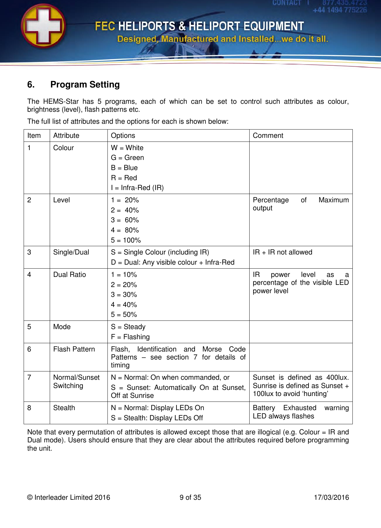
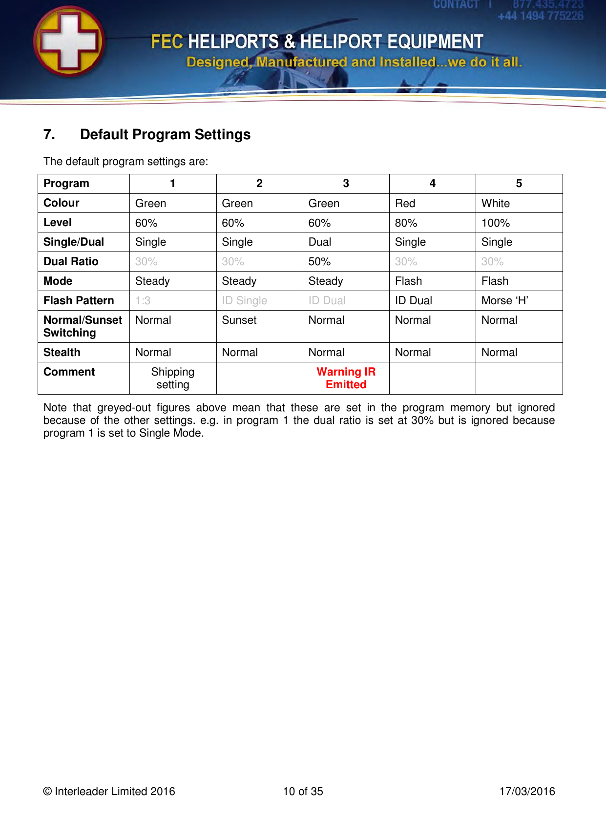
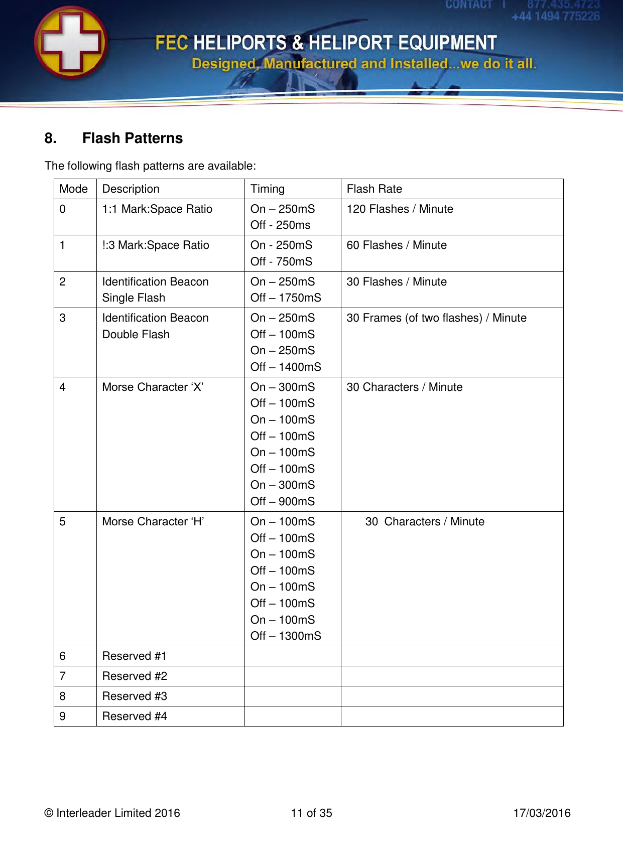
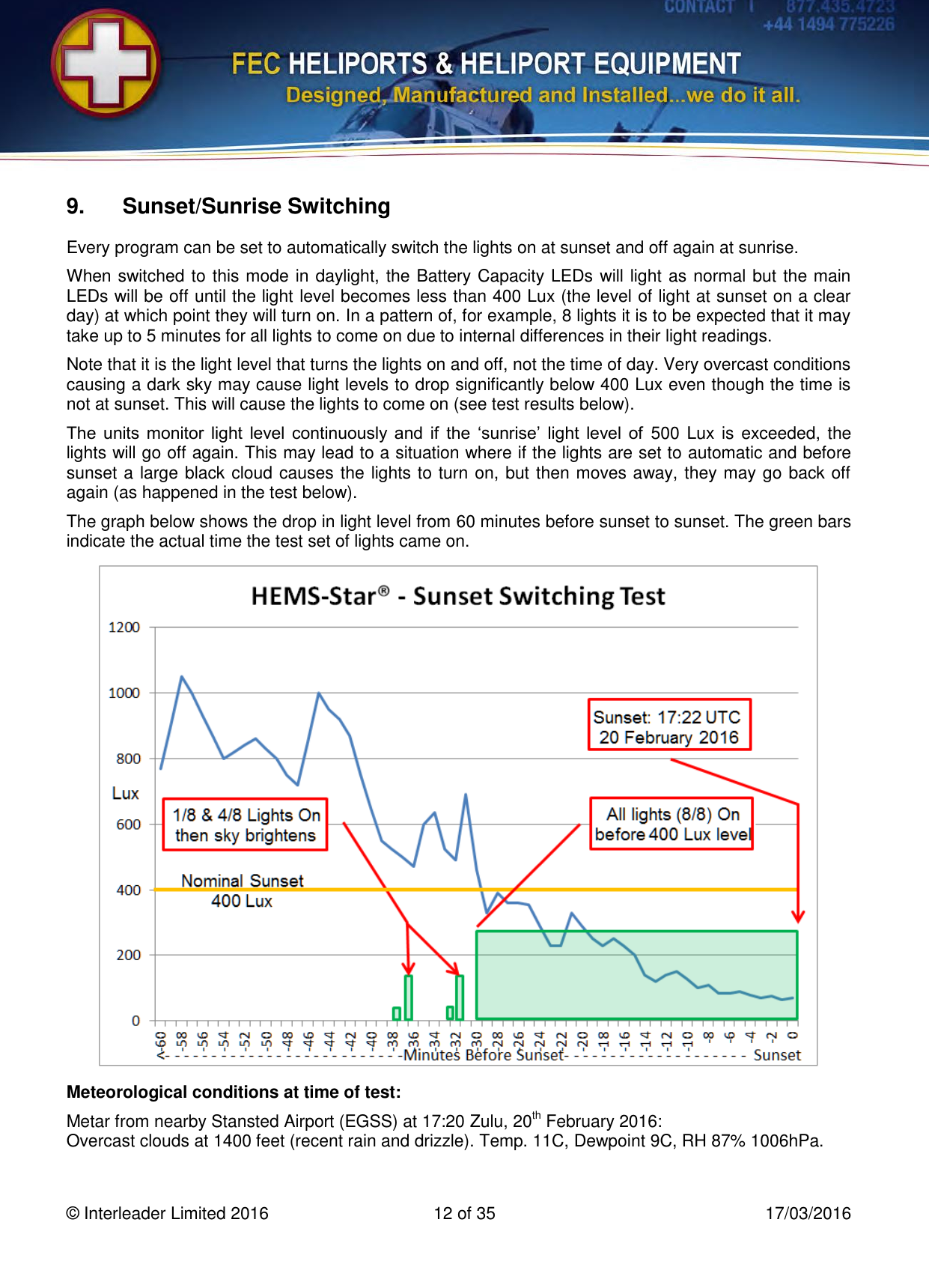
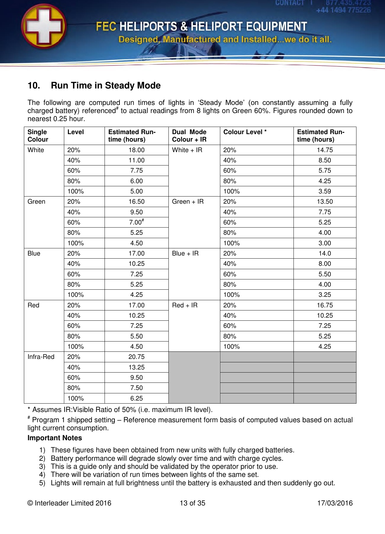
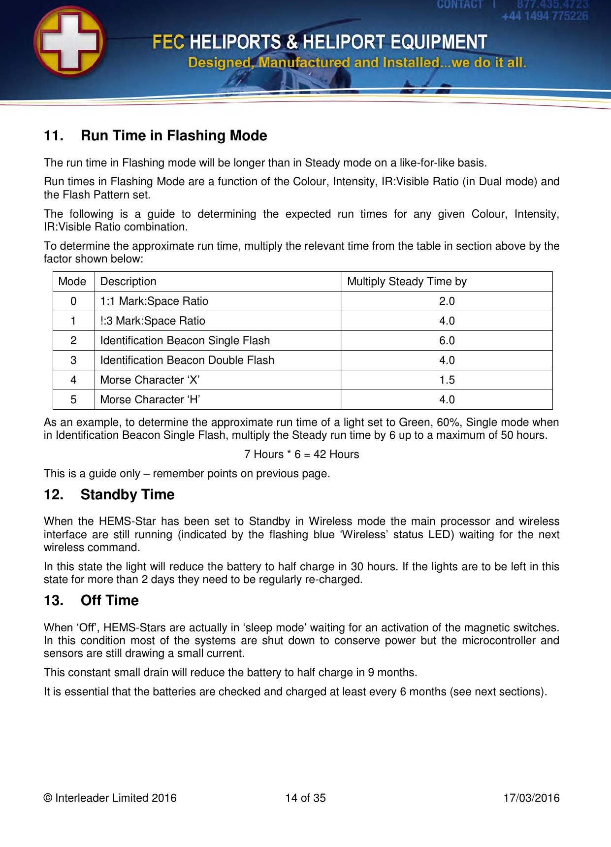
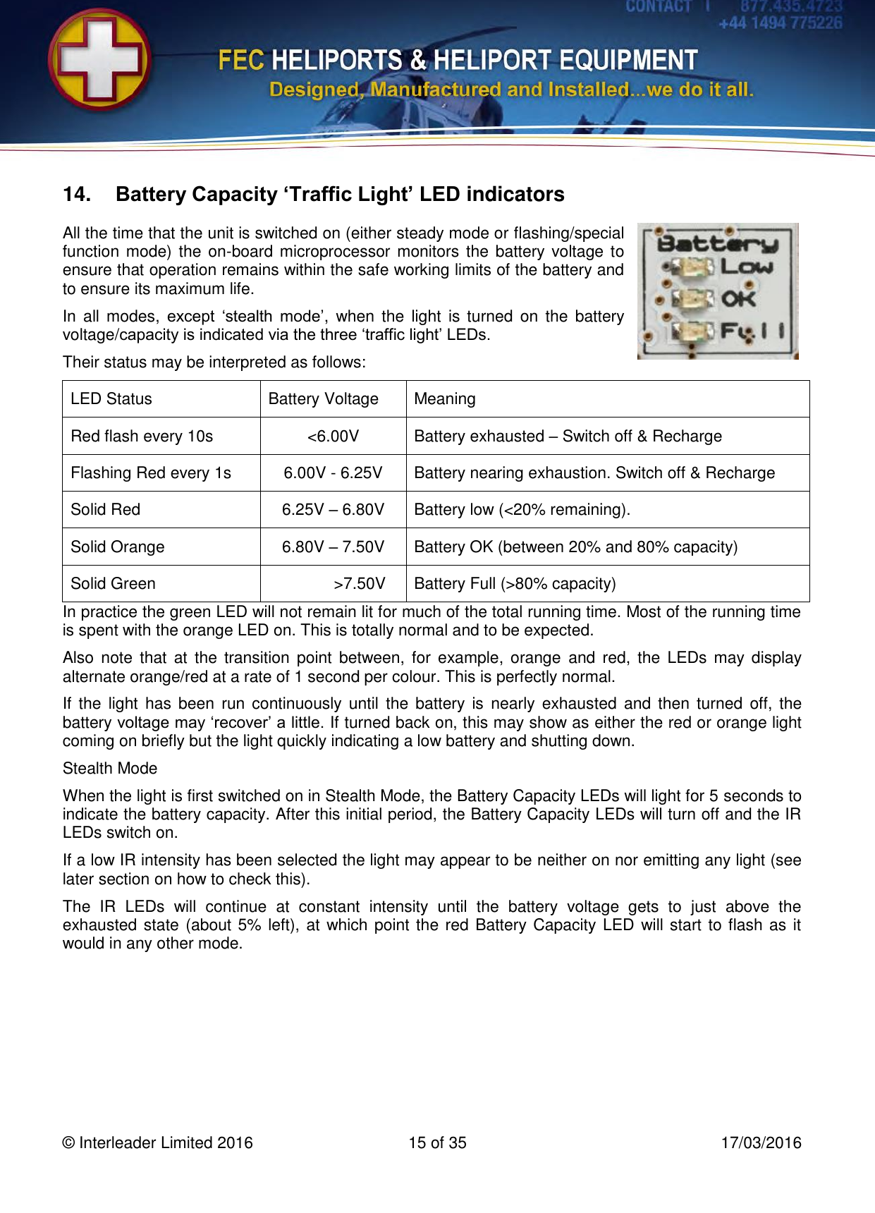
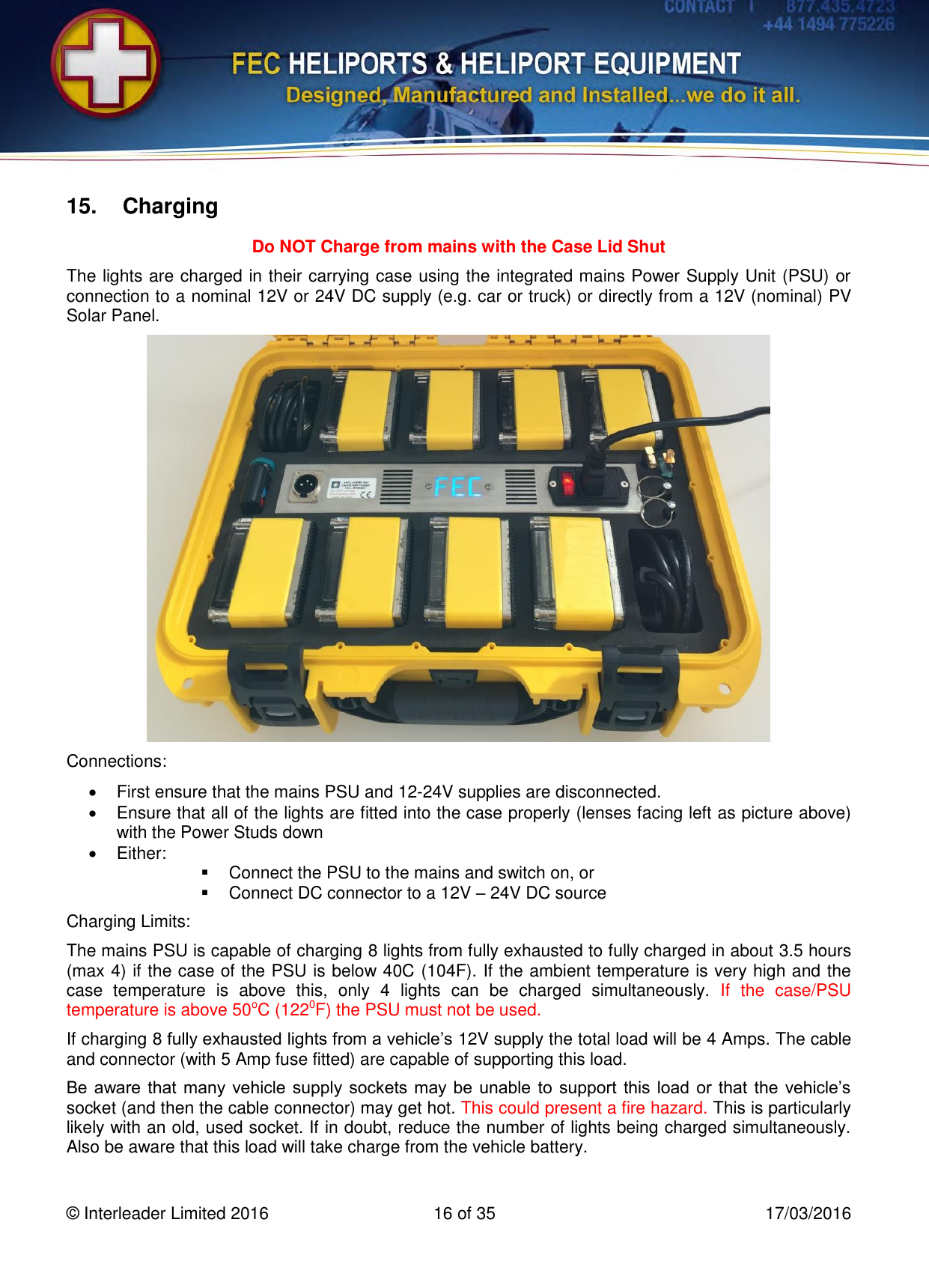
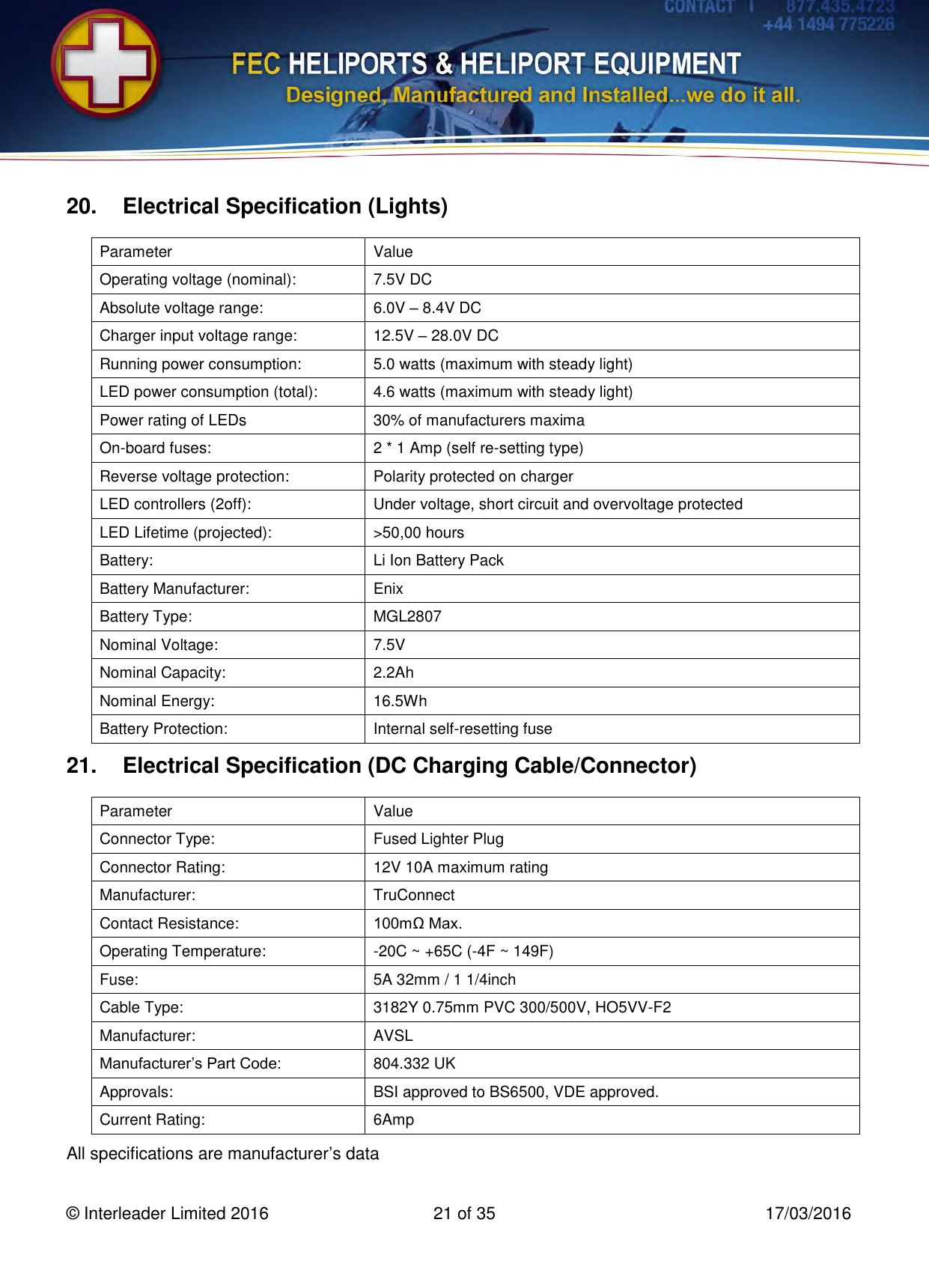
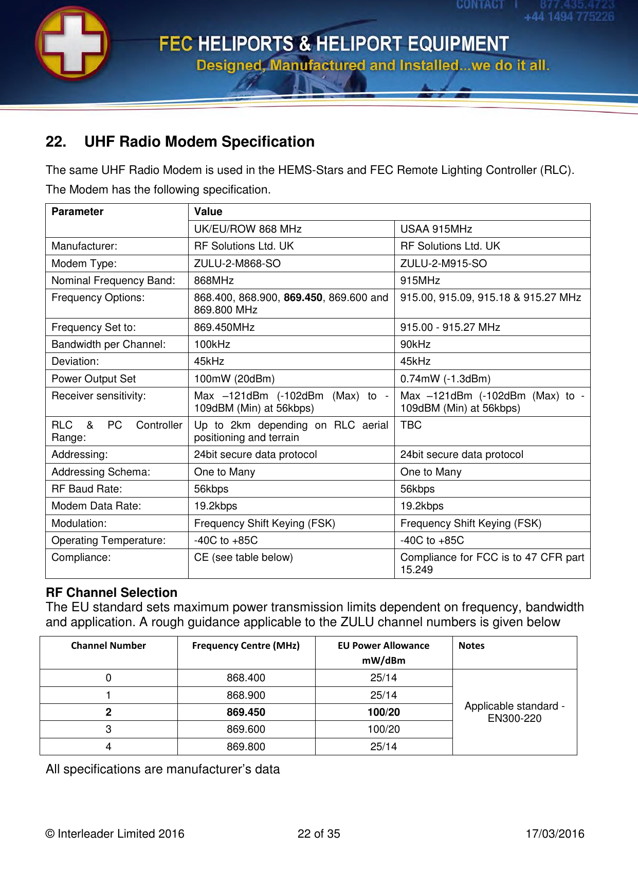
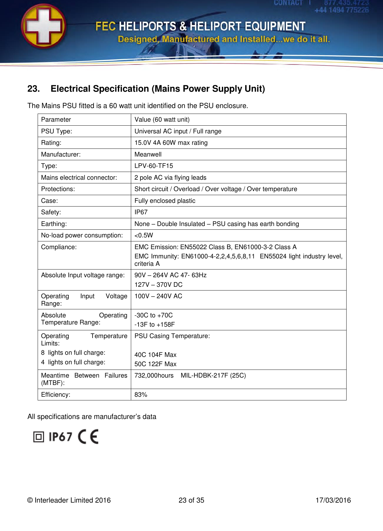
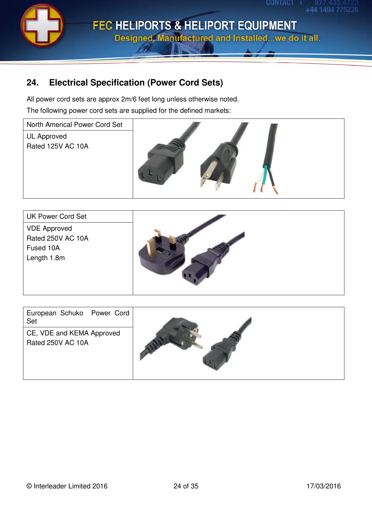
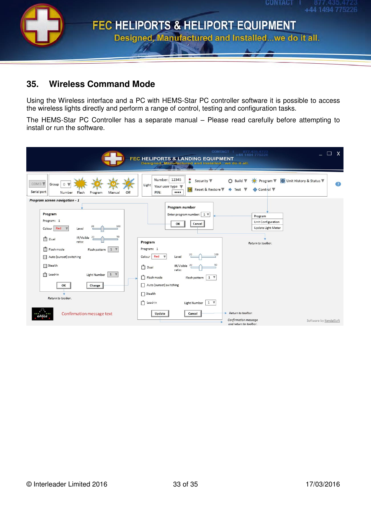
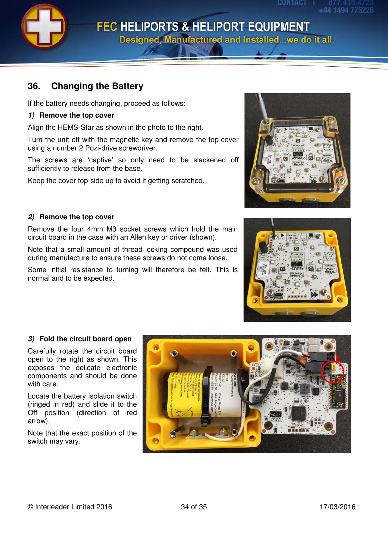
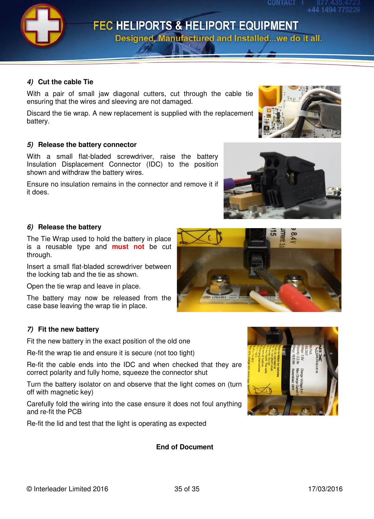
FEC Heliports Worldwide HP0678-6-Z9 HEMS - Star User Manual

FEC Heliports Worldwide Limited HEMS - Star

User manual

      HEMS-Star® FEC Battery LED Helipad Lights Type: FEC - HP0678/6 User Manual – Specification – Diagnostics   HEMS-Star® Battery LED Helipad Light displaying Green  This device emits Infra-Red radiation Never stare at the IR emitters as this may cause eye damage Read this manual before operating the unit  Issue: 1.1         17th March 2016  Powered by eAGLe Light Engines      ® Interleader Limited
  © Interleader Limited 2016  2 of 35  17/03/2016 Document Revision Sheet Issue Date Changes 1.0 21/02/2016 New Document 1.1 17/03/2016 Corrected UHF figures                      HEMS-Star® in alternative case colours             The eAGLe logo and HEMS-Star name are copyright of Interleader Limited 2016
  © Interleader Limited 2016  3 of 35  17/03/2016 Contents 1. Compliance Statements ..............................................................................4 2. Overview .....................................................................................................5 3. The HEMS-Star ...........................................................................................6 4. HEMS-Star Capabilities ...............................................................................7 5. Basic Operation ...........................................................................................8 6. Program Setting ..........................................................................................9 7. Default Program Settings .......................................................................... 10 8. Flash Patterns ........................................................................................... 11 9. Sunset/Sunrise Switching .......................................................................... 12 10. Run Time in Steady Mode ......................................................................... 13 11. Run Time in Flashing Mode ....................................................................... 14 12. Standby Time ............................................................................................ 14 13. Off Time .................................................................................................... 14 14. Battery Capacity ‘Traffic Light’ LED indicators ........................................... 15 15. Charging ................................................................................................... 16 16. Wireless Controller .................................................................................... 18 17. Dimensions ............................................................................................... 19 18. Weight ....................................................................................................... 20 19. Environmental (Lights) .............................................................................. 20 20. Electrical Specification (Lights) .................................................................. 21 21. Electrical Specification (DC Charging Cable/Connector) ........................... 21 22. UHF Radio Modem Specification ............................................................... 22 23. Electrical Specification (Mains Power Supply Unit) .................................... 23 24. Electrical Specification (Power Cord Sets) ................................................ 24 25. LED Colour Characteristics ....................................................................... 26 26. LED Light Intensity – Approximate ............................................................ 26 27. Special Orders .......................................................................................... 27 28. Spare Parts ............................................................................................... 27 29. Support Documentation ............................................................................. 27 30. The Carrying and Charging Case .............................................................. 28 31. Diagnostics and Fault Finding ................................................................... 29 32. Transportation ........................................................................................... 30 33. Packaging and Labelling ........................................................................... 31 34. Software Updater - HEMS-Stars................................................................ 32 35. Wireless Command Mode ......................................................................... 33 36. Changing the Battery ................................................................................. 34
  © Interleader Limited 2016  4 of 35  17/03/2016 1.  Compliance Statements USA FCC Compliance WARNING Changes or modifications to the transmitter not expressly approved by the manufacturer could void the user's authority to operate this RF device. FCC Compliance Statement This  device  complies  with  Part  15  of  the  FCC  Rules.  Operation  is  subject  to  the  following  two conditions: 1. This device may not cause interference, and 2. This device must accept any interference, including interference that may cause undesired operation of the device. USA-Federal Communications Commission (FCC) This  equipment  has  been  tested  and  found  to  comply  with  the  limits  for  a  Class  B  digital  device, pursuant to Part 15 of FCC Rules. These limits are designed to provide reasonable protection against harmful interference in a residential installation. This equipment generates, uses, and can radiate radio frequency energy. If not installed and used in accordance with the instructions, it may cause harmful interference to radio communications. However, there is no ensured specification that interference will not  occur  in  a  particular  installation.  If  this  equipment  does  cause  harmful  interference  to  radio  or television  reception,  which  can  be  determined  by  tuning  the  equipment  off  and  on,  the  user  is encouraged to try and correct the interference by one or more of the following measures: • Reorient or relocate the receiving antenna. • Increase the distance between the equipment and the receiver. • Connect the equipment to outlet on a circuit different from that to which the receiver is connected. • Consult the dealer or an experienced radio/TV technician for help. Any changes or modifications not expressly approved by the party responsible for compliance could void the user’s authority to operate the equipment.  Europe This device carries the CE marking showing it has been tested and shown to be in compliance with: R&TTE Type Testing EN 300 220-1v2.4.1 & EN 300 220-2v2.4.1 EMC Type Testing EN 301 489-1v1.9.2 & EN 301 489-3v1.6.1
  © Interleader Limited 2016  5 of 35  17/03/2016 2.  Overview The  HEMS-Star®  Battery  LED  Helipad  Lights  (In  this manual referred to as the light or lights) are an advanced battery powered, microprocessor controlled helipad light designed  for  rapid  deployment  in  temporary  and emergency  situations  to  provide  safe  and  effective marking.  In  steady  light  mode,  constant  light  level  is achieved  for  up  to  15  hours  before  recharging.  In flashing mode running time is significantly extended. Part Number FEC - HP0678/6  4  colours  +  IR  –  White,  Green,  Blue,  Red  and Infra-Red Model Characteristics The  lights  use  advanced  LED  and  microelectronics  to provide  a  safe  and  effective  lighting  solution  for temporary and emergency situations. The  lights  are  manufactured  in  robust  ABS  and  acrylic  enclosures  with  stainless  steel  fittings  for durability and long life. The lights use magnetic switches, cord-less charging and are sealed to IP65 rating.  The lights have a number of operating modes: steady visible or infra-red, steady visible and infra-red and a number of flash patterns in the above combinations. Configurations of colours, flash patterns and operating modes are stored as 5 selectable programs and groups of lights can be wirelessly controlled.  In steady mode the LEDs provide continuous and constant light output for between 3.75 and 15 hours depending on the colour and intensity level selected. In flashing modes there are 5 selectable flash patterns to choose from. Once selected, the pattern will output each time flash mode is selected. The lights are supplied as a set of up to 8 in a robust Nanuk case which incorporates a mains power supply to simultaneously charge all fitted lights. The  power  source  may  be  110/230V  AC  or  12-24VDC  or  a  12V  nominal  solar  panel  with  cables supplied and connected for both and stored in the case. The lights have 6mm stainless steel bases with rubber anti-skid bottoms.
  © Interleader Limited 2016  6 of 35  17/03/2016 3.  The HEMS-Star A HEMS-Star is shown in the picture below. The  units  are  completely  self-contained  and  incorporate;  microprocessor  main  controller,  magnetic control  switches,  advanced  LED  driver  units,  visible  and  infra-red  LEDs,  Li-Ion  battery,  advanced battery  charging  control  and  monitoring  system,  charging  studs,  USB  port  for  field  upgrade  of  the software  and  a  UHF  wireless  interface  for  programming,  monitoring  and  controlling  the  light  from  either: a Remote Lighting Controller, a PC with the provided wireless ‘dongle’ or an optional Key Fob Controller (KFC).                     Battery Status Indicator LEDs ‘Program’ Sensor ‘On’ Sensor Program Indicator Ring of Visible LEDs Triangle of Infra-Red LEDs Charging Status LEDs Charging Power Studs (on case front) ‘Off’ Sensor USB Port Wireless Status LEDs
  © Interleader Limited 2016  7 of 35  17/03/2016 4.  HEMS-Star Capabilities The  HEMS-Star  lights  incorporate  an  advanced  microcontroller  to  provide  very  flexible  and programmable operation. The HEMS-Star has 5 pre-set Programs which can have any of the following attributes set: Colours (Single Mode) HEMS-Stars are fitted with White, Green, Red and Blue visible and Infra-Red (IR) LEDs. Colours + IR (Dual Mode) There may be instances where pilots require both visible light and infra-red lights in the pattern of light so that they can either use  normal  vision or  augmentation through the use of  Night  Vision Goggles (NVG). Any colour + IR can be selected for Dual Mode Levels (Brightness) The LED output Level is set to 20%, 40%, 60%, 80% or 100% of maximum output level. In Dual mode the ratio of the IR level to the visible LED level can be set at 10%, 20%, 30%, 40% and 50% of the output level of the visible LEDs. Note that as this is a ratio, as the level of the visible LEDs is changed, the IR level tracks it at the desired ratio. Steady/Flashing Modes HEMS-Stars  can  be  set  to  operate  in  Steady  mode  (where  the  LEDs  are  maintained  at  constant brightness) or  Flashing  mode  (where  the  LEDs  are  flashed  at  the  desired  flash  pattern  –  see  later section). Automatic Switching HEMS-Stars incorporate a light detector and can be set to switch in Normal mode (On/Off action solely controlled by the magnetic or wireless switches) or in Sunset mode where they will automatically come on at Sunset and off at Sunrise. Stealth Where it is undesirable to have any status lights showing, Stealth mode provides the facility to turn off the status LEDs after an initial confirmation period (5 seconds). Lead-In Lights A group of HEMS-Stars can operate as a string of sequenced flashing lead-in lights. In this mode each HEMS-Star is programmed with a ‘Light Number’ and, on the receipt of a Flash command, will flash at the right point in the lead-in sequence Basic Switching HEMS-Stars are turned On, Off and have the required Program selected by using a magnet to activate magnetic switches inside the case (Basic Operation – next section) Wireless Switching Once turned on, HEMS-Stars can be controlled by a wireless Remote Lighting Controller or wireless Key Fob Controller (optional extra). See later sections for details.
  © Interleader Limited 2016  8 of 35  17/03/2016 5.  Basic Operation Basic  On/Off/Program  selection  of  the  HEMS-Star is achieved by activating magnetic sensors inside the unit using a small magnet (supplied). Turn HEMS-Star On To turn a  HEMS-Star on, momentarily bring the Magnetic  Key  Controller  (MKC)  in  line  with  the ‘On’  sensor  on  the  unit’s  top  panel  (picture  top right).    Turn HEMS-Star Off To turn a  HEMS-Star off, momentarily  bring  the Magnetic  Key  Controller  (MKC)  in  line  with  the ‘Off’  sensor  on  the  unit’s  top  panel  (picture middle right).  If the unit is off, bringing the MKC in line with the ‘Off’  sensor,  displays  the  current  Program  and battery  status  (useful  for  a  quick  check  without having to turn the unit on)    Advance HEMS-Star Program To advance the HEMS-Star to the next Program, momentarily  bring  the  Magnetic  Key  Controller (MKC)  in  line  with  the  ‘Program’  sensor  on  the unit’s  top  panel  (picture  lower  right).  Program advance is:    The Program can also be advanced with the unit off  in  which  case  the  current  Program  is  briefly shown and then the Program advances by one.
  © Interleader Limited 2016  9 of 35  17/03/2016 6.  Program Setting The  HEMS-Star  has  5  programs,  each  of  which  can  be  set  to  control  such  attributes  as  colour, brightness (level), flash patterns etc. The full list of attributes and the options for each is shown below: Item Attribute Options Comment 1 Colour W = White G = Green B = Blue R = Red I = Infra-Red (IR)  2 Level 1 =  20% 2 =  40% 3 =  60% 4 =  80% 5 = 100% Percentage  of  Maximum output 3 Single/Dual S = Single Colour (including IR) D = Dual: Any visible colour + Infra-Red IR + IR not allowed 4 Dual Ratio 1 = 10% 2 = 20% 3 = 30% 4 = 40% 5 = 50% IR  power  level  as  a percentage of  the visible  LED power level 5 Mode S = Steady F = Flashing  6 Flash Pattern Flash,  Identification  and  Morse  Code Patterns  –  see  section  7  for  details  of timing   7 Normal/Sunset Switching N = Normal: On when commanded, or S  =  Sunset:  Automatically  On  at  Sunset, Off at Sunrise Sunset  is  defined  as  400lux. Sunrise is defined as Sunset + 100lux to avoid ‘hunting’ 8 Stealth N = Normal: Display LEDs On S = Stealth: Display LEDs Off Battery  Exhausted  warning LED always flashes  Note that every permutation of attributes is allowed except those that are illogical (e.g. Colour = IR and Dual mode). Users should ensure that they are clear about the attributes required before programming the unit.
  © Interleader Limited 2016  10 of 35  17/03/2016 7.  Default Program Settings The default program settings are: Program 1 2 3 4 5 Colour Green Green Green Red White Level 60% 60% 60% 80% 100% Single/Dual Single Single Dual Single Single Dual Ratio 30% 30% 50% 30% 30% Mode Steady Steady Steady Flash Flash Flash Pattern 1:3 ID Single ID Dual ID Dual Morse ‘H’ Normal/Sunset Switching Normal Sunset Normal Normal Normal Stealth Normal Normal Normal Normal Normal Comment Shipping setting  Warning IR Emitted   Note  that  greyed-out  figures  above  mean  that  these  are  set  in  the  program  memory  but  ignored because of the other settings. e.g. in program 1 the dual ratio is set at 30% but is ignored because program 1 is set to Single Mode.
  © Interleader Limited 2016  11 of 35  17/03/2016 8.  Flash Patterns The following flash patterns are available: Mode Description Timing Flash Rate 0 1:1 Mark:Space Ratio  On – 250mS Off - 250ms 120 Flashes / Minute 1 !:3 Mark:Space Ratio On - 250mS Off - 750mS 60 Flashes / Minute 2 Identification Beacon Single Flash On – 250mS Off – 1750mS 30 Flashes / Minute  3 Identification Beacon Double Flash On – 250mS Off – 100mS On – 250mS Off – 1400mS 30 Frames (of two flashes) / Minute 4 Morse Character ‘X’ On – 300mS Off – 100mS On – 100mS Off – 100mS On – 100mS Off – 100mS On – 300mS Off – 900mS 30 Characters / Minute 5 Morse Character ‘H’ On – 100mS Off – 100mS On – 100mS Off – 100mS On – 100mS Off – 100mS On – 100mS Off – 1300mS 30  Characters / Minute 6 Reserved #1   7 Reserved #2   8 Reserved #3   9 Reserved #4
  © Interleader Limited 2016  12 of 35  17/03/2016 9.  Sunset/Sunrise Switching Every program can be set to automatically switch the lights on at sunset and off again at sunrise. When switched to this mode in daylight, the Battery Capacity LEDs will light as normal but the main LEDs will be off until the light level becomes less than 400 Lux (the level of light at sunset on a clear day) at which point they will turn on. In a pattern of, for example, 8 lights it is to be expected that it may take up to 5 minutes for all lights to come on due to internal differences in their light readings.  Note that it is the light level that turns the lights on and off, not the time of day. Very overcast conditions causing a dark sky may cause light levels to drop significantly below 400 Lux even though the time is not at sunset. This will cause the lights to come on (see test results below). The  units  monitor  light  level  continuously  and  if  the  ‘sunrise’  light  level  of  500 Lux is  exceeded, the lights will go off again. This may lead to a situation where if the lights are set to automatic and before sunset a large black cloud causes the lights to turn on, but then moves away, they may go back off again (as happened in the test below). The graph below shows the drop in light level from 60 minutes before sunset to sunset. The green bars indicate the actual time the test set of lights came on.  Meteorological conditions at time of test: Metar from nearby Stansted Airport (EGSS) at 17:20 Zulu, 20th February 2016: Overcast clouds at 1400 feet (recent rain and drizzle). Temp. 11C, Dewpoint 9C, RH 87% 1006hPa.
  © Interleader Limited 2016  13 of 35  17/03/2016 10.  Run Time in Steady Mode The  following  are  computed  run  times  of  lights  in  ‘Steady  Mode’  (on  constantly  assuming  a  fully charged battery) referenced# to actual readings from 8 lights on Green 60%. Figures rounded down to nearest 0.25 hour. Single Colour Level Estimated Run-time (hours) Dual  Mode Colour + IR Colour Level * Estimated Run-time (hours) White 20% 18.00 White + IR 20% 14.75 40% 11.00 40% 8.50 60% 7.75 60% 5.75 80% 6.00 80% 4.25 100% 5.00 100% 3.59 Green 20% 16.50 Green + IR 20% 13.50 40% 9.50 40% 7.75 60% 7.00# 60% 5.25 80% 5.25 80% 4.00 100% 4.50 100% 3.00 Blue 20% 17.00 Blue + IR 20% 14.0 40% 10.25 40% 8.00 60% 7.25 60% 5.50 80% 5.25 80% 4.00 100% 4.25 100% 3.25 Red 20% 17.00 Red + IR 20% 16.75 40% 10.25 40% 10.25 60% 7.25 60% 7.25 80% 5.50 80% 5.25 100% 4.50 100% 4.25 Infra-Red 20% 20.75    40% 13.25   60% 9.50   80% 7.50   100% 6.25   * Assumes IR:Visible Ratio of 50% (i.e. maximum IR level). # Program 1 shipped setting – Reference measurement form basis of computed values based on actual light current consumption. Important Notes 1)  These figures have been obtained from new units with fully charged batteries. 2)  Battery performance will degrade slowly over time and with charge cycles.  3)  This is a guide only and should be validated by the operator prior to use. 4)  There will be variation of run times between lights of the same set. 5)  Lights will remain at full brightness until the battery is exhausted and then suddenly go out.
  © Interleader Limited 2016  14 of 35  17/03/2016 11.  Run Time in Flashing Mode The run time in Flashing mode will be longer than in Steady mode on a like-for-like basis. Run times in Flashing Mode are a function of the Colour, Intensity, IR:Visible Ratio (in Dual mode) and the Flash Pattern set. The  following  is  a  guide  to  determining  the  expected  run  times  for  any  given  Colour,  Intensity, IR:Visible Ratio combination. To determine the approximate run time, multiply the relevant time from the table in section above by the factor shown below: Mode Description Multiply Steady Time by 0 1:1 Mark:Space Ratio  2.0 1 !:3 Mark:Space Ratio 4.0 2 Identification Beacon Single Flash 6.0 3 Identification Beacon Double Flash 4.0 4 Morse Character ‘X’ 1.5 5 Morse Character ‘H’ 4.0 As an example, to determine the approximate run time of a light set to Green, 60%, Single mode when in Identification Beacon Single Flash, multiply the Steady run time by 6 up to a maximum of 50 hours. 7 Hours * 6 = 42 Hours This is a guide only – remember points on previous page. 12.  Standby Time When  the  HEMS-Star  has  been  set  to  Standby in Wireless  mode the main  processor  and  wireless interface  are  still  running  (indicated by the  flashing  blue  ‘Wireless’  status  LED)  waiting  for  the  next wireless command. In this state the light will reduce the battery to half charge in 30 hours. If the lights are to be left in this state for more than 2 days they need to be regularly re-charged. 13. Off Time When ‘Off’, HEMS-Stars are actually in ‘sleep mode’ waiting for an activation of the magnetic switches. In  this  condition most of the  systems are shut  down to conserve power but  the microcontroller  and sensors are still drawing a small current. This constant small drain will reduce the battery to half charge in 9 months. It is essential that the batteries are checked and charged at least every 6 months (see next sections).
  © Interleader Limited 2016  15 of 35  17/03/2016 14. Battery Capacity ‘Traffic Light’ LED indicators All the time that the unit is switched on (either steady mode or flashing/special function mode) the  on-board microprocessor  monitors the battery voltage to ensure that operation remains within the safe working limits of the battery and to ensure its maximum life.  In  all  modes,  except  ‘stealth  mode’,  when the  light  is turned  on  the  battery voltage/capacity is indicated via the three ‘traffic light’ LEDs. Their status may be interpreted as follows: LED Status Battery Voltage Meaning Red flash every 10s <6.00V Battery exhausted – Switch off & Recharge Flashing Red every 1s 6.00V - 6.25V Battery nearing exhaustion. Switch off & Recharge Solid Red 6.25V – 6.80V Battery low (<20% remaining). Solid Orange 6.80V – 7.50V Battery OK (between 20% and 80% capacity) Solid Green >7.50V Battery Full (>80% capacity) In practice the green LED will not remain lit for much of the total running time. Most of the running time is spent with the orange LED on. This is totally normal and to be expected. Also  note  that  at  the  transition  point  between,  for  example,  orange  and  red,  the  LEDs  may  display alternate orange/red at a rate of 1 second per colour. This is perfectly normal. If  the  light has  been  run  continuously  until  the  battery  is  nearly  exhausted  and then turned  off,  the battery voltage may ‘recover’ a little. If turned back on, this may show as either the red or orange light coming on briefly but the light quickly indicating a low battery and shutting down. Stealth Mode When the light is first switched on in Stealth Mode, the Battery Capacity LEDs will light for 5 seconds to indicate the battery capacity. After this initial period, the Battery Capacity LEDs will turn off and the IR LEDs switch on. If a low IR intensity has been selected the light may appear to be neither on nor emitting any light (see later section on how to check this). The  IR  LEDs  will  continue  at  constant  intensity  until  the  battery  voltage  gets  to  just  above  the exhausted state (about 5% left), at which point the red Battery Capacity LED will start to flash as it would in any other mode.
  © Interleader Limited 2016  16 of 35  17/03/2016 15.  Charging Do NOT Charge from mains with the Case Lid Shut The lights are charged in their carrying case using the integrated mains Power Supply Unit (PSU) or connection to a nominal 12V or 24V DC supply (e.g. car or truck) or directly from a 12V (nominal) PV Solar Panel.  Connections:   First ensure that the mains PSU and 12-24V supplies are disconnected.   Ensure that all of the lights are fitted into the case properly (lenses facing left as picture above) with the Power Studs down   Either:   Connect the PSU to the mains and switch on, or   Connect DC connector to a 12V – 24V DC source Charging Limits: The mains PSU is capable of charging 8 lights from fully exhausted to fully charged in about 3.5 hours (max 4) if the case of the PSU is below 40C (104F). If the ambient temperature is very high and the case  temperature  is  above  this,  only  4  lights  can  be  charged  simultaneously.  If  the  case/PSU temperature is above 50oC (1220F) the PSU must not be used. If charging 8 fully exhausted lights from a vehicle’s 12V supply the total load will be 4 Amps. The cable and connector (with 5 Amp fuse fitted) are capable of supporting this load. Be aware that  many vehicle  supply sockets may  be  unable to  support  this load  or  that  the  vehicle’s socket (and then the cable connector) may get hot. This could present a fire hazard. This is particularly likely with an old, used socket. If in doubt, reduce the number of lights being charged simultaneously. Also be aware that this load will take charge from the vehicle battery.
  © Interleader Limited 2016  17 of 35  17/03/2016 Battery Status LEDs:   When power is first  applied to the  lights,  the  internal charging circuit first determines the state of the battery, only going to full charge if the battery passes the initial test. If there is a problem with the battery the red Fault LED will be lit. See later section on action to take.   The  charger  is  an  intelligent  dual-rate  charger  and, after  the  initial  battery  check,  will  determine  exactly how  long  to  charge  the  battery  and  at  what  rate, switching off automatically at the end of the main charge. During the initial high charge rate the Charging LED will be lit. This will extinguish once the battery is fully charged.  After Charging:   Once fully charged (and with the charger still connected and switched on) all LEDs will be off.  At this point turn off the charger.  Li-Ion batteries have a very low self-discharge current and neither need nor benefit from trickle charging.   A refresh cycle should be performed once every 6 month (more frequently in very hot conditions – see table below) to maintain full charge and best battery condition and life. Temperature Remaining Capacity After 23oC / 73oF  95% 6 months 45oC / 113oF  80% 3 months 60oC / 140oF  80% 1 month Dis-Connection:    To disconnect the charger, switch off the mains supply and remove the power cord or disconnect the DC power cable  Re-store the cable Good Practice:   Never charge batteries from the mains power supply with the case lid shut  DO NOT leave charger connected and ‘trickle charging’   Always isolate from the mains before connecting/disconnecting   Only charge batteries indoors in dry conditions   Keep batteries away from sources of heat and direct sunlight    Routinely recycle as outlined above   Never charge a battery that appears damaged   Never use a power cord that is damaged in any way If in doubt – have it checked out
  © Interleader Limited 2016  18 of 35  17/03/2016 16.  Wireless Controller All lights are shipped in manual mode and will operate at the colour and intensity selected by default Program 1 (Green, 60% of max) when first turned on. Manual and Wireless Modes All lights will come on in manual mode and the blue Wireless LED will be off.        The wireless (blue LED) will light when the unit is in ‘Standby’ wireless mode.  Wireless Groups To enable control of a specific group of lights in a situation where multiple groups are deployed (for example, multiple adjacent pads), all lights belong to a ‘Group’. Groups of lights will then respond to Wireless PC Controller or Remote Lighting Controllers (RLC) set to that group number. Lights are shipped set at Group 0 (as is the RLC default settings). If multiple groups of lights are to be controlled then each set needs to have their Group set using the wireless PC Controller software.    Wireless LED (Blue)
  © Interleader Limited 2016  19 of 35  17/03/2016 17.  Dimensions Lights (each) Dimension Value (mm/inches) Comment Width 84mm  / 3.31 inches  Length 83mm  / 3.26 inches Including Power Studs Height 65mm  / 2.56 inches Including 6mm base – Standard product   Case (without packaging)   Case (with shipping packaging) Dimension Value (mm/inches) Width 430mm  / 16.9 inches Length 360mm  / 14.2 inches Height 185mm  / 7.3 inches    Dimension Value (mm/inches) Width 424mm  / 16.7 inches Length 340mm  / 13.4 inches Height 173mm  / 6.8 inches
  © Interleader Limited 2016  20 of 35  17/03/2016 18.  Weight The weight of the individual lights and complete sets (8 lights, case, charger and mains and DC cables) are as follows: Item Weight (kilograms) Weight (US pounds) Comment Single  Battery  LED  Helipad  Light (6mm Stainless Steel base) 0.73kg 1.61lb 6mm Standard base Case  –  Empty  (including  power supply and mains and DC cables) 4.76kg 10.49lb  System:  8  Helipad  Lights  in  Case (including  power  supply  and  mains and DC cables) 10.60kg 23.37lb Operational  system weight System packed for Shipping TBC TBC As  above  but  with  outer foam and shipping box  19.  Environmental (Lights)   Degree of protection IP65   HEMS-Star Operating temperature: -25oC to +40oC   Charging temperature: -25oC to +40oC   System Storage temperature: -25oC to +50oC   Shock – TBC   Fully ROHC Compliant
  © Interleader Limited 2016  21 of 35  17/03/2016 20.  Electrical Specification (Lights) Parameter Value Operating voltage (nominal):   7.5V DC Absolute voltage range: 6.0V – 8.4V DC Charger input voltage range: 12.5V – 28.0V DC Running power consumption: 5.0 watts (maximum with steady light) LED power consumption (total): 4.6 watts (maximum with steady light) Power rating of LEDs 30% of manufacturers maxima On-board fuses: 2 * 1 Amp (self re-setting type) Reverse voltage protection: Polarity protected on charger LED controllers (2off):   Under voltage, short circuit and overvoltage protected LED Lifetime (projected): >50,00 hours Battery: Li Ion Battery Pack Battery Manufacturer: Enix Battery Type: MGL2807 Nominal Voltage: 7.5V Nominal Capacity: 2.2Ah Nominal Energy: 16.5Wh Battery Protection: Internal self-resetting fuse 21.  Electrical Specification (DC Charging Cable/Connector) Parameter Value Connector Type: Fused Lighter Plug Connector Rating: 12V 10A maximum rating Manufacturer: TruConnect Contact Resistance: 100mΩ Max. Operating Temperature: -20C ~ +65C (-4F ~ 149F) Fuse: 5A 32mm / 1 1/4inch Cable Type: 3182Y 0.75mm PVC 300/500V, HO5VV-F2  Manufacturer: AVSL Manufacturer’s Part Code: 804.332 UK Approvals: BSI approved to BS6500, VDE approved. Current Rating: 6Amp All specifications are manufacturer’s data
  © Interleader Limited 2016  22 of 35  17/03/2016 22. UHF Radio Modem Specification The same UHF Radio Modem is used in the HEMS-Stars and FEC Remote Lighting Controller (RLC). The Modem has the following specification. Parameter Value UK/EU/ROW 868 MHz USAA 915MHz Manufacturer: RF Solutions Ltd. UK RF Solutions Ltd. UK Modem Type: ZULU-2-M868-SO  ZULU-2-M915-SO  Nominal Frequency Band: 868MHz 915MHz Frequency Options: 868.400, 868.900, 869.450, 869.600 and 869.800 MHz 915.00, 915.09, 915.18 & 915.27 MHz Frequency Set to: 869.450MHz 915.00 - 915.27 MHz Bandwidth per Channel: 100kHz 90kHz Deviation: 45kHz 45kHz Power Output Set 100mW (20dBm) 0.74mW (-1.3dBm) Receiver sensitivity: Max  –121dBm  (-102dBm  (Max)  to  -109dBM (Min) at 56kbps) Max  –121dBm  (-102dBm  (Max)  to  -109dBM (Min) at 56kbps) RLC  &  PC  Controller Range: Up  to  2km  depending  on  RLC  aerial positioning and terrain  TBC Addressing: 24bit secure data protocol 24bit secure data protocol Addressing Schema: One to Many One to Many RF Baud Rate:  56kbps 56kbps Modem Data Rate: 19.2kbps 19.2kbps Modulation: Frequency Shift Keying (FSK) Frequency Shift Keying (FSK) Operating Temperature: -40C to +85C -40C to +85C Compliance: CE (see table below) Compliance for FCC is to 47 CFR part 15.249 RF Channel Selection The EU standard sets maximum power transmission limits dependent on frequency, bandwidth and application. A rough guidance applicable to the ZULU channel numbers is given below  Channel Number Frequency Centre (MHz) EU Power Allowance mW/dBm Notes 0 868.400 25/14 Applicable standard - EN300-220 1 868.900 25/14 2 869.450 100/20 3 869.600 100/20 4 869.800 25/14 All specifications are manufacturer’s data
  © Interleader Limited 2016  23 of 35  17/03/2016 23.  Electrical Specification (Mains Power Supply Unit) The Mains PSU fitted is a 60 watt unit identified on the PSU enclosure. Parameter Value (60 watt unit) PSU Type: Universal AC input / Full range Rating: 15.0V 4A 60W max rating Manufacturer: Meanwell Type:   LPV-60-TF15 Mains electrical connector: 2 pole AC via flying leads Protections: Short circuit / Overload / Over voltage / Over temperature Case: Fully enclosed plastic Safety: IP67 Earthing: None – Double Insulated – PSU casing has earth bonding No-load power consumption: <0.5W Compliance: EMC Emission: EN55022 Class B, EN61000-3-2 Class A EMC Immunity: EN61000-4-2,2,4,5,6,8,11  EN55024 light industry level, criteria A Absolute Input voltage range: 90V – 264V AC 47- 63Hz 127V – 370V DC Operating  Input  Voltage Range: 100V – 240V AC Absolute  Operating Temperature Range: -30C to +70C -13F to +158F Operating  Temperature Limits: 8  lights on full charge: 4  lights on full charge: PSU Casing Temperature:  40C 104F Max 50C 122F Max Meantime  Between  Failures (MTBF): 732,000hours  MIL-HDBK-217F (25C) Efficiency: 83%    All specifications are manufacturer’s data
  © Interleader Limited 2016  24 of 35  17/03/2016 24.  Electrical Specification (Power Cord Sets) All power cord sets are approx 2m/6 feet long unless otherwise noted. The following power cord sets are supplied for the defined markets:  North Americal Power Cord Set  UL Approved Rated 125V AC 10A   UK Power Cord Set  VDE Approved Rated 250V AC 10A Fused 10A Length 1.8m   European  Schuko    Power  Cord Set  CE, VDE and KEMA Approved Rated 250V AC 10A
  © Interleader Limited 2016  25 of 35  17/03/2016 Electrical Specification (Power Cord Sets) Continued The following power cord sets are available as additional cost options: Australia & New Zealand  Power Cord Set  SAA(13389),  IMQ,  SEV,  VDE, KEMA,  SEMKO,  DEMKO, NEMKO, FIMKO Approved Rated 250V AC 10A   Danish  Power Cord Set  DEMKO,  SEV,  SAA(13389), VDE,  KEMA,  SEMKO,  NEMKO, FIMKO Approved Rated 250V AC 10A   Italian  Power Cord Set  IMQ,  SEV,  SAA(13389),  VDE, KEMA,  SEMKO,  DEMKO, NEMKO,  FIMKO  and  other approvals Rated 250V AC 10A   Contact your FEC representative for details of other options.
  © Interleader Limited 2016  26 of 35  17/03/2016 25.  LED Colour Characteristics   White            6000oK/6500oK ‘Cool White’   Green            528nm   Blue            470nm   Red            625nm   Infra-Red          940nm  Options At additional cost and subject to a Minimum Order Quantity (MOQ), units can be supplied with a range of colour LEDs including:   Deep Blue          455nm   Yellow           590nm   Red-Orange          617nm   Hyper Red          656nm  26.  LED Light Intensity – Approximate The following gives an indication of the measured light level obtained from the units at different vertical angles and with different colour LEDs.  Colour White Green Blue Red Angle of Elevation 20% 60% 100% 20% 60% 100% 20% 60% 100% 20% 60% 100% -5             0             5             10             15             20             25             30             45             90              As standard, lights are delivered set to Program 1: Green, 60% max output
  © Interleader Limited 2016  27 of 35  17/03/2016 27.  Special Orders Software Features At additional cost, units can be programmed to perform non-standard functions including:   Different string lengths of Morse Code   Alternative flash patterns   Customer specified timing or operation Please contact your FEC sales representative to discuss your particular requirements. 28.  Spare Parts The Li-Ion battery is a user changeable item. There are no other user serviceable parts. Items requiring repair need to be returned to FEC 29.  Support Documentation Documentation,  including  this  manual,  is  contained  on  the USB memory stick in the case (colour of USB stick will vary). Also  on  the  USB  memory  stick  are  short  video  clips  that demonstrate  various  aspects  of  setting  up  and  using  the lights and charger. Updates may also be posted on the FEC website.  Material on the USB Stick: There  are  a  number  of  folders  on  the  USB  Memory  Stick containing: Application Files PC Controller Software Battery Data Manufacturers declaration about the battery HEMS-Star Software Software running the lights KFC Software   Software for the optional Key Fob Controller Labels   Battery shipping labels Manuals HEMS-Star summary (flier in case) HEMS-Star manual (this document) HEMS-Star PC Controller manual Key Fob Controller manual Videos Short videos showing basic operations HEMS-Star  PC Controller V1.0 HEMS-Star PC Controller software Setup Setup file for PC Controller Software
  © Interleader Limited 2016  28 of 35  17/03/2016 30.  The Carrying and Charging Case The carrying case can accommodate up to 8 lights, has an integrated 100-240V AC Power Supply Unit (PSU) and leads for connection to either the mains supply (for the PSU) or a vehicle nominal 12-24V DC supply. Note – Non-standard light cases shown.                         Always charge lights from the mains with the case lid fully open Lights and PSU may overheat causing fire risk and permanent damage if lid is closed during charging Documentation on USB Memory Stick 8 Light Positions Magnetic Key Controllers (2) 12V – 24V DC Charging Cable 100 – 240V AC Charging Cable Optional Wireless Key Fob 12V – 24V DC or PV Solar Connector 100 – 240V AC Connector Wireless Zulu Dongle and antenna
  © Interleader Limited 2016  29 of 35  17/03/2016 31.  Diagnostics and Fault Finding The following are the range of simple tests that an end-user of the light can perform – to be carried out in the order given. Warning   The lights emit high brightness light pulses and/or Infra-Red. Do not look directly at the LED arrays or near reflections of the light. Basic Visual Checks – Ensure that:   The unit is properly mounted, secure and appears physically undamaged  There are no signs of overheating or leakage (could indicate a split battery)  Basic Operational Checks – Ensure that:   The magnetic switches operates correctly   If the unit comes on but: 1.  In steady mode – the light flashes briefly and then goes out (indicates an exhausted battery), or 2.  In flash mode the correct sequence is not followed, Check the charge state of the battery   If the unit does not come on at all, go to next step   If  unsure  of  the  charge  state  of  the  battery,  connect  to  the  charger  and  ensure  that  the charge cycle is as follows: 1.  There  may  be a  brief  period  before  the  Green  ‘Charging’  LED  comes  on  (charger controller is checking the state of the battery) 2. The Green ‘Charging’  LED comes  on an  stays on for  up  to  4 hours (indicates bulk charge cycle) 3. The Green ‘Charging’ LED then goes off (indicates that the charger has entered the trickle charge phase).   If at any  time  during  charging  the  Red  ‘Fault’ LED  comes  on  it  indicates  a  fault  has  been detected by the charger circuit – most likely with the battery. 1.  The first time this happens, disconnect the power and wait 5 minutes before trying again as the fault may clear 2. Repeated display of the Red ‘Fault’ LED indicates a serious fault and the light should be returned to FEC for rectification Returning the Light: Defective Li-Ion batteries are not permitted to be air transported.   Turn off the light   Securely wrap the light in protective foam or similar   Send the light to FEC for repair – by a permitted carrier (see next section)
  © Interleader Limited 2016  30 of 35  17/03/2016 32.  Transportation Defective Li-Ion batteries are not permitted to be air transported. Batteries  are  subject  to  special  conditions  when  transported,  particularly  by  air.  The  relevant ICAO/IATA documents make the following Provision (A67): IATA-ICAO Provision A67 for the carriage of Batteries A67  Non-spillable batteries meeting the requirements of Packing Instruction 872 are not subject to these Regulations if, at a temperature of 55ºC (131ºF), the electrolyte will not flow from a ruptured or cracked case. The  battery must  not contain any  free or  unabsorbed liquid. Any  electrical battery or battery powered device, equipment or vehicle having the potential of dangerous evolution of heat must be prepared for transport so as to prevent: (a)  a short circuit (e.g. in the case of batteries, by the effective insulation of exposed terminals; or in the case of equipment, by disconnection of the battery and protection of exposed terminals); and (b)  unintentional activation  The  words  “Not  Restricted”  and  the  Special  Provision  number  must  be  included  in  the description of the substance on the Air Waybill as required by 8.2.6, when an Air Waybill is issued. The batteries used in the FEC HEMS-Star have been qualified by the manufacturer to be compliant with this provision.
  © Interleader Limited 2016  31 of 35  17/03/2016 33.  Packaging and Labelling Repack the lights in the case and fit the case into its original cardboard box. Attach a warning label to the inner box. Fit the inner box into the outer protective cardboard box with foam liner. Attach another warning label to the outer box. A sample label is included on the memory stick for you to enter your contact details onto.
  © Interleader Limited 2016  32 of 35  17/03/2016 34.  Software Updater - HEMS-Stars The  HEMS-Star  can  be  updated  with  new  software  by  users. Software  updates  are  available  as  downloads  from  the  FEC website.  Two formats  are supported;  executable (.exe)  and  self-extracting zip files. If your PC firewall prevents downloading of the .exe file, download and extract the zip file version. To update the software requires a Windows PC and a USB cable with  type  ‘A’  plug  one  end  and  Micro  type  ‘B’  the  other.  The installer  requires  neither  software  nor  drivers  to  be  installed  on your PC – the standard Windows HID drivers already installed are used. To update the software: 1)  Turn the HEMS-Star unit off 2)  Open the enclosure as described in earlier section 3)  Connect the USB cable to the PC (not yet to HEMS-Star) 4)  Double click on the update file and a screen similar to that to the top-right will appear 5)  Hold  the  Magnetic  Key  to  the  ‘Off’  position  –  all  of  the program LEDs will flash – keep holding until they all come on solid. Take away the magnetic key. 6)  Insert  the  micro  USB  plug  into the  socket  on  the  HEMS-Star 7)  The screen on the PC should now advise that the system is connected  and  the  Install  button  will  have  changed  from greyed-out to active.   If  screen  does  not  confirm  it  is  ready  to  install, remove the cable from  the  HEMS-Star  and  repeat from instruction 6 8)  Click Install and the software will be automatically uploaded to the HEMS-Star 9)  A screen (right) confirms the update in progress 10) When complete:   All of the HEMS-Star Program LEDs will extinguish   The PC Window will advise  it  is finished  – click finish and the window will close 11) If Windows asks if the programme installed ok – click yes  12) Disconnect the USB cable 13) Reassemble  the  controller  and  turn  on  in  the  usual  way with the magnetic key. 14) The HEMS-Star will now be running the new software Note that the serial number and wireless type are retained during an upgrade but all other settings revert to factory defaults.
  © Interleader Limited 2016  33 of 35  17/03/2016 35.  Wireless Command Mode Using the Wireless interface and a PC with HEMS-Star PC controller software it is possible to access the wireless lights directly and perform a range of control, testing and configuration tasks. The  HEMS-Star  PC  Controller  has  a  separate  manual  –  Please  read carefully  before  attempting to install or run the software.
  © Interleader Limited 2016  34 of 35  17/03/2016 36.  Changing the Battery If the battery needs changing, proceed as follows: 1) Remove the top cover Align the HEMS-Star as shown in the photo to the right. Turn the unit off with the magnetic key and remove the top cover using a number 2 Pozi-drive screwdriver. The  screws  are  ‘captive’  so  only  need  to  be  slackened  off sufficiently to release from the base. Keep the cover top-side up to avoid it getting scratched.   2) Remove the top cover Remove  the  four  4mm  M3  socket  screws  which  hold  the  main circuit board in the case with an Allen key or driver (shown). Note that a small amount of thread locking compound was used during manufacture to ensure these screws do not come loose. Some  initial  resistance  to  turning  will  therefore  be  felt.  This  is normal and to be expected.     3) Fold the circuit board open Carefully  rotate  the  circuit  board open  to the  right  as  shown.  This exposes  the  delicate  electronic components  and  should  be  done with care. Locate the battery isolation switch (ringed  in  red) and  slide  it to  the Off  position  (direction  of  red arrow). Note that the exact position of the switch may vary.
  © Interleader Limited 2016  35 of 35  17/03/2016 4) Cut the cable Tie With  a  pair  of  small  jaw  diagonal  cutters,  cut  through  the  cable  tie ensuring that the wires and sleeving are not damaged. Discard the tie wrap. A new replacement is supplied with the replacement battery.  5) Release the battery connector  With  a  small  flat-bladed  screwdriver,  raise  the  battery Insulation  Displacement  Connector  (IDC)  to  the  position shown and withdraw the battery wires. Ensure no insulation remains in the connector and remove it if it does.   6) Release the battery The Tie Wrap used to hold the battery in place is  a  reusable  type  and  must  not be  cut through. Insert a small flat-bladed screwdriver between the locking tab and the tie as shown. Open the tie wrap and leave in place. The  battery  may  now  be  released  from  the case base leaving the wrap tie in place.   7) Fit the new battery Fit the new battery in the exact position of the old one Re-fit the wrap tie and ensure it is secure (not too tight) Re-fit  the cable  ends  into  the  IDC and  when checked  that  they  are correct polarity and fully home, squeeze the connector shut Turn the battery isolator on and observe that the light comes on (turn off with magnetic key) Carefully fold the wiring into the case ensure it does not foul anything and re-fit the PCB Re-fit the lid and test that the light is operating as expected  End of Document

Navigation menu