FEDDERS Air Conditioner Room (42) Manual L0811032
User Manual: FEDDERS FEDDERS Air Conditioner Room (42) Manual FEDDERS Air Conditioner Room (42) Owner's Manual, FEDDERS Air Conditioner Room (42) installation guides
Open the PDF directly: View PDF ![]() .
.
Page Count: 8
Installation & Operations Manual
Room air conditioners for
double hung windows
ENGLISH
Important Safety Instructions .................................. 2
Installation
Window installation .............................................. 3
Operation
Electronic controls ...................... 5
Cleaning the air filter ..............................................
Service/Troubleshootin 8 .......................................... 7
Warranty .................................................................. 8
Write down the model and serial numbers
The model and serial numbers can be found on the side of the
cabinet near the control panel. Use these numbers in any cor-
respondence or service calls concerning your air conditioner. Model No.
Serial No.
Date of Purchase
23-23-0363N-002
i INSTALLATION "_
ELECTRICAL REQUIREMENTS& SAFETY PREGAUTIDNS J
Electrical Shock Hazard _Zk
•Plug unit only into a grounded _[_
electrical outlet.
• Do not use an extension cord or plug
adapter with this unit.
• Do not operate unit with decorative front
or filter removed.
Failure to follow these precautions could
result in electrical shock, fire or personal
injury.
If the air conditioner has a serial plate
rating of 115 volts and greater than 7.5
amps, it must have its own fuse or circuit
breaker, and no other device or unit
should be operated on that fuse or circuit
breaker.
If the air conditioner has a serial plate
rating of 230 volts, it must have its own
fuse or circuit breaker, and no other
device or unit should be operated on that
fuse or circuit breaker.
We recommend that a qualified electrician
install unit in accordance with the
National Electrical Code and local codes
and ordinances.
• Use copper conductors of correct wire
gauge and protector size only.
• Do not alter cord or plug end. Do not
remove warning label on cord.
Important Grounding Requirements
• Air conditioner has a three-prong
grounding plug on the power supply cord,
which must be plugged into a properly
grounded three-prong wall receptacle for
your protection against possible shock
hazard. For models up to and including
7.5 amperes, use a grounding type wall
receptacle to match the cord plug.
• For models above 7.5 amperes use a single
outlet grounding type wall receptacle to
match the cord plug.
Do not operate this air conditioner without
proper time delay circuit protection (circuit
breaker or fuse). Refer to serial plate for
proper power supply requirements.
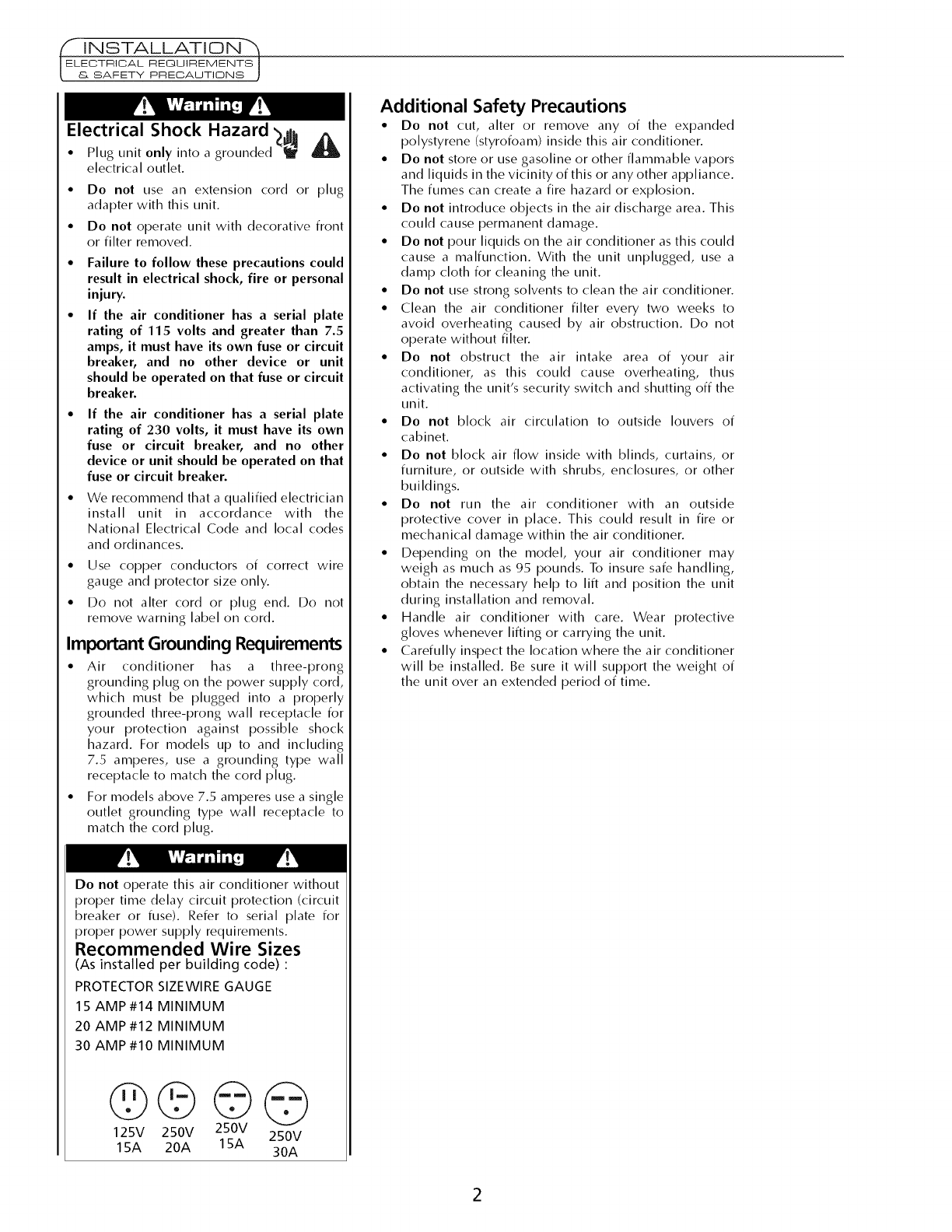
Recommended Wire Sizes
(As installed per building code) :
PROTECTOR SIZEWIRE GAUGE
15 AMP #14 MINIMUM
20 AMP#12 MINIMUM
30 AMP#10 MINIMUM
©©©©
125V 250V 250V 250V
15A 20A 15A 30A
Additional Safety Precautions
• Do not cut, alter or remove any of the expanded
polystyrene (styrofoam) inside this air conditioner.
• Do not store or use gasoline or other flammable vapors
and liquids in the vicinity of this or any other appliance.
The fumes can create a fire hazard or explosion.
• Do not introduce objects in the air discharge area. This
could cause permanent damage.
• Do not pour liquids on the air conditioner as this could
cause a malfunction. With the unit unplugged, use a
damp cloth for cleaning the unit.
• Do not use strong solvents to clean the air conditioner.
• Clean the air conditioner filter every two weeks to
avoid overheating caused by air obstruction. Do not
operate without filter.
• Do not obstruct the air intake area of your air
conditioner, as this could cause overheating, thus
activating the unit's security switch and shutting off the
unit.
• Do not block air circulation to outside louvers of
cabinet.
• Do not block air flow inside with blinds, curtains, or
furniture, or outside with shrubs, enclosures, or other
buildings.
• Do not run the air conditioner with an outside
protective cover in place. This could result in fire or
mechanical damage within the air conditioner.
• Depending on the model, your air conditioner may
weigh as much as 95 pounds. To insure safe handling,
obtain the necessary help to lift and position the unit
during installation and removal.
• Handle air conditioner with care. Wear protective
gloves whenever lifting or carrying the unit.
• Carefully inspect the location where the air conditioner
will be installed. Be sure it will support the weight of
the unit over an extended period of time.
(I iN STALLATIO N"_
WINDOW IN STALLATDNJ
Tools Needed
•Screwdrivers _•Ruler
//
/._ tape measure
•Level _ • Pencil_
or
Window Requirements
1, Air conditioner is factory prepared for installation in standard double hung
window (air conditioner cannot be installed in other types of windows with-
out modification, consult with a qualified installation serviceman).
2, Install the air conditioner in a window where there will be enough clearance
around the cabinet to allow ample circulation of air through the unit.
3, All supporting parts should be secured to firm wood, masonry or metal.
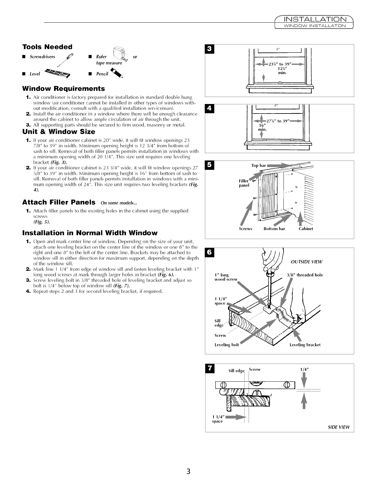
Unit & Window Size
1. If your air conditioner cabinet is 20" wide, it will fit window openings 23
7/8" to 39" in width. Minimum opening height is ]2 3/4" from bottom of
sash to sill. Removal of both filler panels permits installation in windows with
a minimum opening width of 20 ]/4". This size unit requires one leveling
bracket (Fig. 3).
2, If your air conditioner cabinet is 23 3/4" wide, it will fit window openings 27
5/8" to 39" in width. Minimum opening height is ]6" from bottom of sash to
sill Removal of both filler panels permits installation in windows with a mini-
mum opening width of 24". This size unit requires two leveling brackets (Fig.
4).
Attach Filler Panels o,, somemodels...
1. Attach filler panels to the existing holes in the cabinet using the supplied
screws
(Fig. 5).
Installation in Normal Width Window
1. ()pen and mark center line of window. Depending on the size of your unit,
attach one leveling bracket on the center line of the window or one 8" to the
right and one 8" to the left of the center line. Brackets may be attached to
window sill in either direction for maximum support, depending on the depth
of the window sill.
2. Mark line I 1/4" from edge of window sill and fasten leveling bracket with 1"
long wood screws at mark through larger holes in bracket (Fig,.6).
3. Screw leveling bolt in 3/8" threaded hole of leveling bracket and adjust so
bolt is 1/4" below top of window sill (Fig. 7).
4. Repeat steps 2 and 3 for second leveling bracket, if required.
I;I
r,I
kii
i/23 1 9, i
L4/ z--ILk
I I
I.... ]
_27A to 39'_H
Screws Bottom bar Cabinet
1" long
wood screw
OUTSIDE VIEW
3/8" threaded hole
Screw
Leveling bolt Leveling bracket
U Sill edg_ Screw
1 1/4"_
space
1/4"
®
SIDE VIEW
INSTALLATION
WINDOW INSTALLATON "_
El
Lower
Top bar
i
d
(
p
"3
0
.)
o
_Bottom bar _
1 1/4"space Leveling bracket
Window sill
Sill edge Screw SIDE VIEW
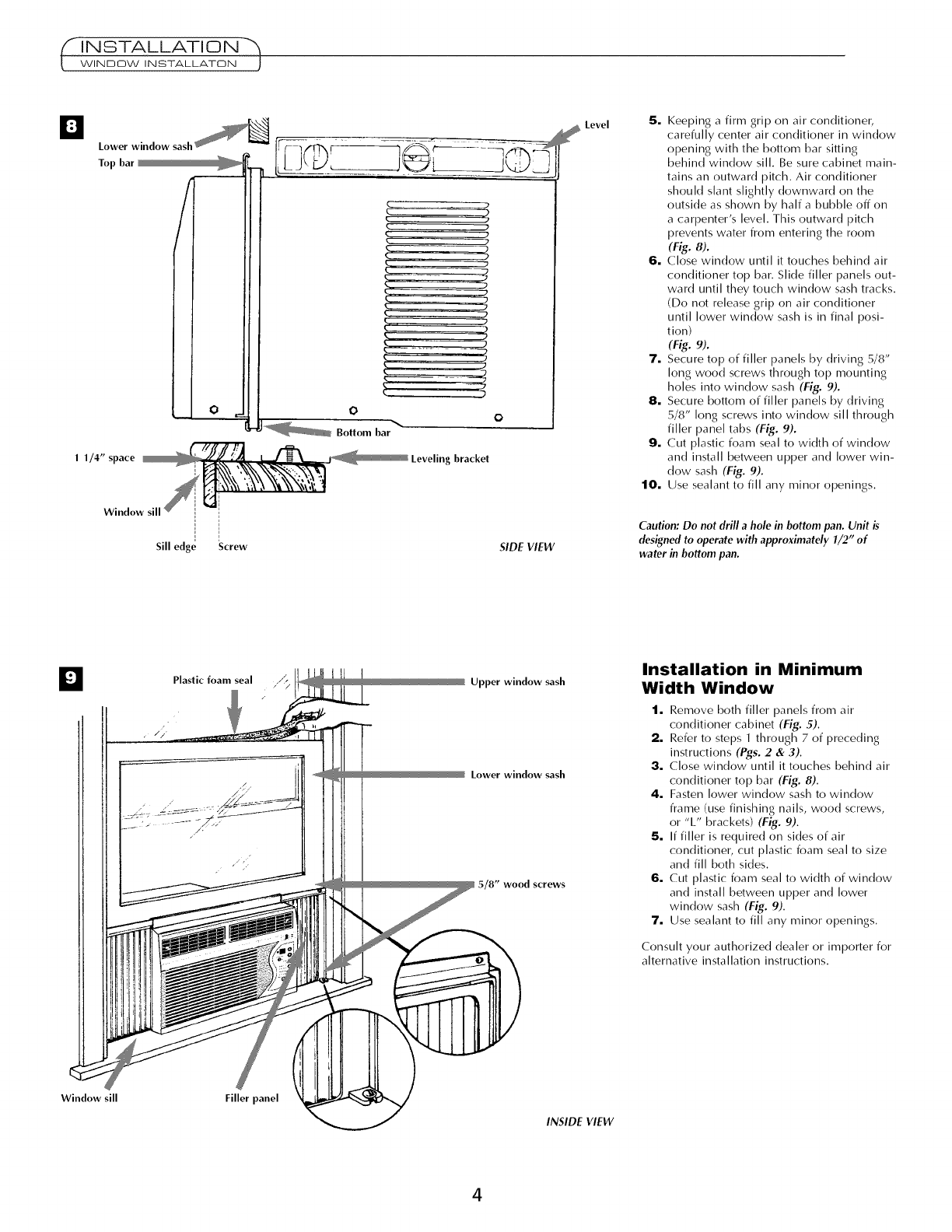
5. Keeping a firm grip on air conditioner,
carefully center air conditioner in window
opening with the bottom bar sitting
behind window sill. Be sure cabinet main-
tains an outward pitch. Air conditioner
shoukt slant slightly downward on the
outside as shown by half a bubble off on
a carpenter's level. This outward pitch
prevents water from entering the room
(Fig._).
6. Close window until it touches behind air
conditioner top bar. Slide filler panels out-
ward until they touch window sash tracks.
(Do not release grip on air conditioner
until lower window sash is in final posi-
tion)
(Fig.9).
7. Secure top of filler panels by driving 5/8"
long wood screws through top mounting
holes into window sash (Fig. 9).
8. Secure bottom of filler panels by driving
5/8" long screws into window sill through
filler panel tabs (Fig. 9).
9. Cut plastic foam seal to width of window
and install between upper and lower win-
dow sash (Fig. 9).
10. Use sealant to fill any minor openings.
Caution: Do not drill a hole in bottom pan. Unit is
designed to operate with approximately 1/2" of
water in bottom pan.
Plastic foam seal ,/'_ Upper window sash
Lower window sash
5/8" wood screws
Installation in Minimum
Width Window
1. Remove both filler panels from air
conditioner cabinet (Fig. 5).
2. Refer to steps 1through 7 of preceding
instructions (Pgs. 2& 3).
3. Close window until it touches behind air
conditioner top bar (Fig. 8).
4. Fasten lower window sash to window
frame (use finishing nails, wood screws,
or "L" brackets) (Fig. 9).
5. If filler is required on sides of air
conditioner, cut plastic foam seal to size
and fill both sides.
6. Cut plastic foam seal to width of window
and install between upper and lower
window sash (Fig. 9).
7. Use sealant to fill any minor openings.
Consult your authorized dealer or importer for
alternative installation instructions,
Window sill Filler panel
INSIDE VIEW
4
•TIMER
.... S
• MED
•COOL•FAN D
ON/OF_ ........................A
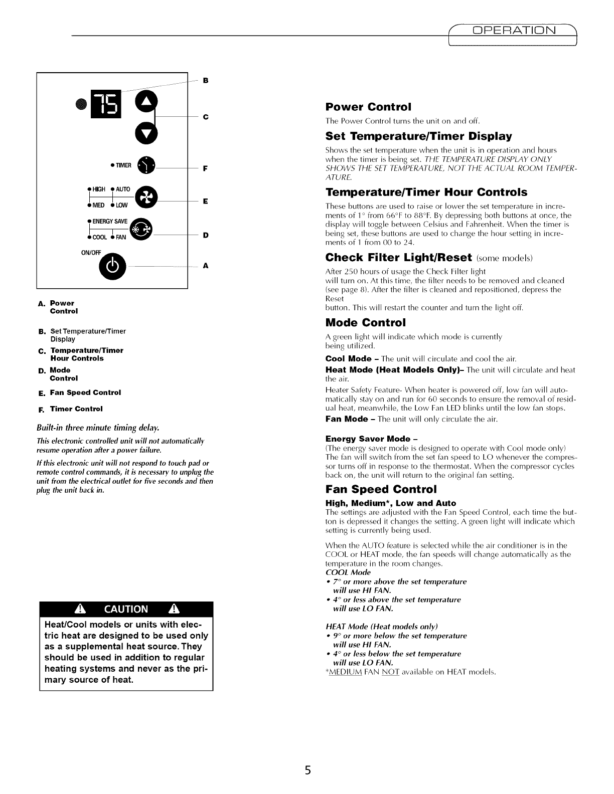
A. Power
Control
B. Set Temperature/Timer
Display
C. Temperature/Timer
Hour Control•
D. Mode
Control
E. Fan Speed Control
F. Timer Control
Built-in three minute timing delay.
This electronic controlled unit will not automatically
resume operation after a power failure.
If this electronic unit will not respond to touch pad or
remote control commands, it is necessary to unplug the
unit from the electrical outlet for five seconds and then
plug the unit back in.
pv_ Ea_:,lujn/[o_ _
Heat/Cool models or units with elec-
tric heat are designed to be used only
as a supplemental heat source. They
should be used in addition to regular
heating systems and never as the pri-
mary source of heat.
OPERATION ")
Power Control
The Power Control turns the unit on and off.
Set Temperature/Timer Display
Shows the set temperature when the unit is in operation and hours
when the timer is being set. THE TEMPERATURE DISPLAY ONLY
SHOWS THE SET TEMPERATURE, NOT THE ACTUAL ROOM TEMPER-
ATURE.
Temperature/Timer Hour Controls
These buttons are used to raise or lower the set temperature in incre-
ments of 1o from 66°F to 88°F. By depressing both buttons at once, the
display will toggle between Celsius and Fahrenheit. When the timer is
being set, these buttons are used to change the hour setting in incre-
ments of I from 00 to 24.
Check Filter Light/Reset (somemodels)
After 250 hours of usage the Check Filter light
will turn on. At this time, the filter needs to be removed and cleaned
(see page 8). After the filter is cleaned and repositioned, depress the
Reset
button. This will restart the counter and turn the light off.
Mode Control
A green light will indicate which mode is currently
being utilized.
Cool Mode - The unit will circulate and cool the air.
Heat Mode (Heat Models Only)- The unit will circulate and heat
the air.
Heater Safety Feature- When heater is powered off, low fan will auto-
matically stay on and run for 60 seconds to ensure the removal of resid-
ual heat, meanwhile, the Low Fan LED blinks until the low fan stops.
Fan Mode - The unit will only circulate the air.
Energy Saver Mode -
(The energy saver mode is designed to operate with Cool mode only)
The fan will switch from the set fan speed to LO whenever the compres-
sor turns off in response to the thermostat. When the compressor cycles
back on, the unit will return to the original fan setting.
Fan Speed Control
High, Medium*, Low and Auto
The settings are adjusted with the Fan Speed Control, each time the [)Lit-
ton is depressed it changes the setting. A green light will indicate which
setting is currently being used.
When the AUTO feature is selected while the air conditioner is in the
COOL or HEAT mode, the fan speeds will change automatically as the
temperature in the room changes.
COOL Mode
•7°or more above the set temperature
will use HI FAN.
•4°or less above the set temperature
will use LO FAN.
HEAT Mode (Heat models only)
•9°or more below the set temperature
will use HI FAN.
•4°or less below the set temperature
will use LO FAN.
*MEDIUM FAN NOT available on HEAT models.
E ©PER#!I©N
t E-ECTRON,CCON -RO'S J
Timer Control
The timer can he set to either turn the unit
On or Off,
To turn the unit on using the Timer:
Depress the timer key when the power is off, the display will read 00. Adjust to
the desired number of hours before TURN ON using the up/down arrows.
•The display will show the time by hours left until
TURN ON.
•To Turn the timer off, depress the timer key.
•A green light next to the Timer Control indicates
that the timer is set.
To turn the unit OFF using the Timer:
Depress the timer key when the power is on, the display will read 00. Adjust to
the desired number of hours before TURN OFF using the up/down arrows. The
display will automatically go back to the set temperature after 10 seconds.
*To display the amount of time left until TURN
OFF, depress the timer button once.
• To turn the TIMER OFF, depress the timer button
twice.
• A green light next to the Timer Control indicates
that the timer is set.
.... S
c
e'iIMER _ i
•MED • LOW
eCOOL eFAN D
ONIOFF0 .............. A
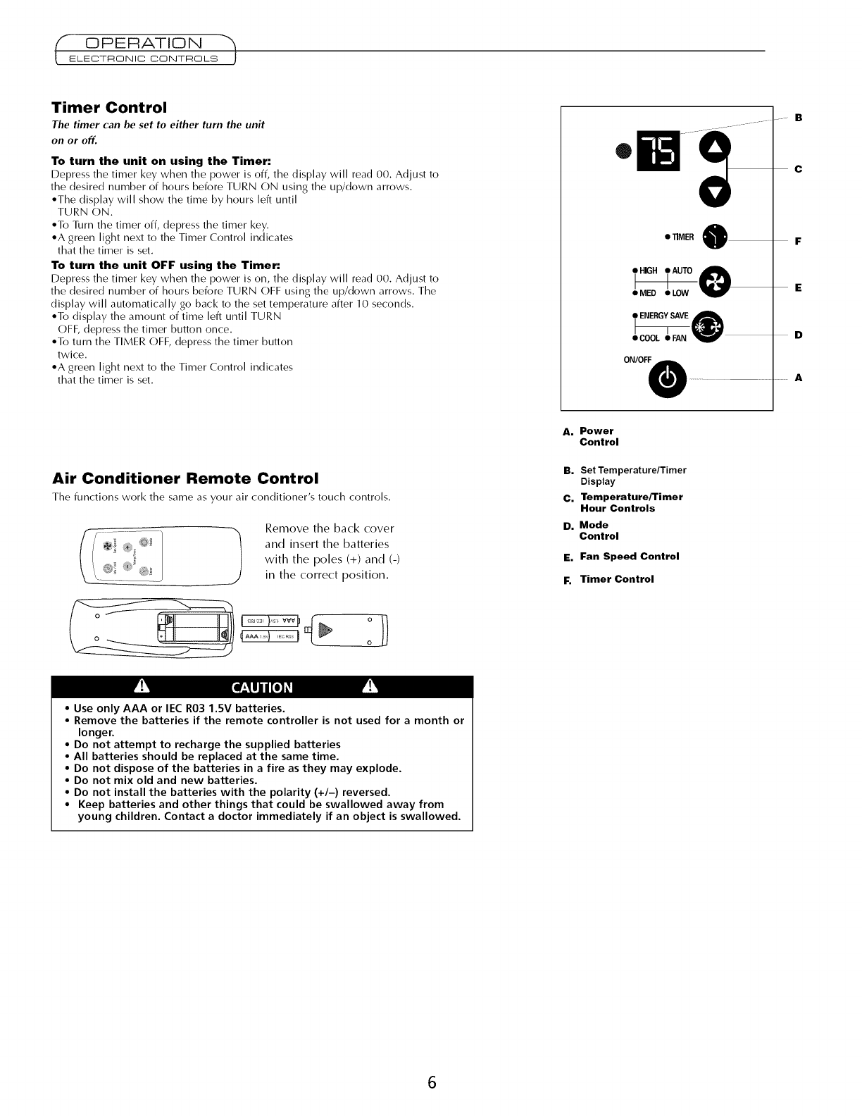
Air Conditioner Remote Control
The functions work the same as your air conditioner's touch controls,
@! k Remove the back cover
and insert the batteries
with the poles (+) and (-)
in the correct position.
A. Power
Control
B. Set Temperature/Timer
Display
C. Temperature/Timer
Hour Controls
D. Mode
Control
E. Fan Speed Control
F. Timer Control
• Use only AAA or lEG R03 1.5V batteries.
• Remove the batteries if the remote controller is not used for a month or
longer.
• Do not attempt to recharge the supplied batteries
• All batteries should be replaced at the same time.
• Do not dispose of the batteries in a fire as they may explode.
• Do not mix old and new batteries.
• Do not install the batteries with the polarity (+/-) reversed.
• Keep batteries and other things that could be swallowed away from
young children. Contact a doctor immediately if an object is swallowed.
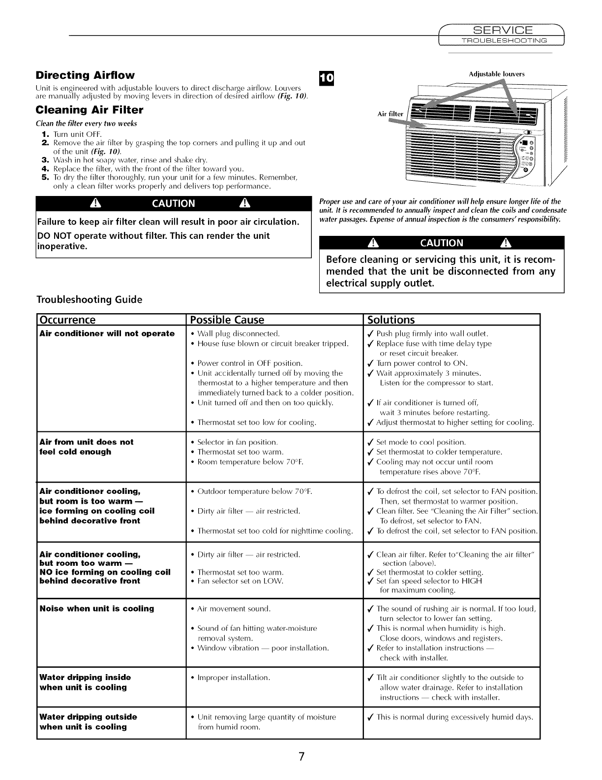
Directing Airflow
Unit is engineered with adustablej Iouvers_ to direct discharge airflow. Louvers
are manually adjusted by moving levers in direction of desired airflow (Fig. 10).
Cleaning Air Filter
Clean the filter every two weeks
1. Turn unit OFF.
2. Remove the air filter by grasping the top corners and pulling it up and out
of the unit (Fig. fO).
3, Wash in hot soapy water, rinse and shake dry.
4. Replace the filter, with the front of the filter toward you.
5. To dry the filter thoroughly, run your unit for a few minutes. Remember,
only a clean filter works properly and delivers top performance.
Adjustable louvers
Air filter
Proper use and care of your air conditioner will help ensure longer life of the
unit. It is recommended to annually inspect and clean the coils and condensate
water passages. Expense of annual inspection is the consumers' responsibility.
Troubleshooting Guide
Occurrence
Air conditioner will not operate
Air from unit does not
feel cold enough
Air conditioner cooling,
but room is too warm --
ice forming on cooling coil
behind decorative front
Air conditioner cooling,
but room too warm --
NO ice forming on cooling coil
behind decorative front
Noise when unit is cooling
Water dripping inside
when unit is cooling
Before cleaning or servicing this unit, it is recom-
mended that the unit be disconnected from any
electrical supply outlet.
Possible Cause
•Wall plug disconnected. _/
• House fuse blown or circuit breaker tripped.
• Power control in (:)FF position. €"
• Unit accidentally turned off by moving the _/
thermostat to a higher temperature and then
immediately turned back to a colder position.
• Unit turned off and then on too quickly. _/
• Thermostat set too low for cooling.
• Selector in fan position.
• Thermostat set too warm.
• Room temperature below 70°F.
• (:)utdoor temperature below 70°F.
• Dirty air filter air restricted,
• Thermostat set too cold for nighttime cooling.
• Dirty air filter air restricted.
• Thermostat set too warm.
• Fan selector set on LOW,
• Air movement sound,
• Sound of fan hitting water-moisture
removal system.
• Window vibration poor installation.
• Improper installation.
Solutions
Push plug firmly into wall outlet.
Replace fuse with time delay type
or reset circuit breaker.
Turn power control to (:)N.
Wait approximately 3 minutes.
Listen for the compressor to start.
/
If air conditioner is turned off,
wait 3 minutes before restarting.
Adjust thermostat to higher setting for cooling.
_/ Set mode to cool position.
_/Set thermostat to colder temperature.
Cooling may not occur until room
temperature rises above 70°F.
/
/
/
/
/
/
To defrost the coil, set selector to FAN position.
Then, set thermostat to warmer position.
(:lean filter. See "(::leaning the Air Filter" section.
To defrost, set selector to FAN.
To defrost the coil, set selector to FAN position.
Clean air filter. Refer to"Cleaning the air filter"
section (above).
Set thermostat to colder setting.
Set fan speed selector to HIGH
for maximum cooling.
V" The sound of rushing air is normal. If too loud,
turn selector to lower fan setting.
V" This is normal when humidity is high.
Close doors, windows and registers.
Refer to installation instructions
check with installer.
/Tilt air conditioner slightly to the outside to
allow water drainage. Refer to installation
instructions check with installer.
Water dripping outside • Unit removing large quantity of moisture _/This is normal during excessively humid clays.
when unit is cooling from humid room.
7
'- WARRANTY ")
How to Obtain Warranty Service or
Parts
Note: Before calling for service, carefully read this
Installation and Operations manual.
For Models Installed in North America :
First make the recommended checks in the
Troubleshooting guide on page 7. Then, if you
still need assistance:
1. Call a CareCo authorized servicer and advise
them of model number, serial number, date of
purchase and nature of complaint. Service will
be provided during normal working hours.
Contact your dealer for the name of an
authorized servicer, if unknown to you.
2. If your dealer is unable to give you the name of
a servicer or if you need other assistance,
contact CareCo for the name of an authorized
servicer.
You may contact CareCo by email:
customerservice@fedders.com
by calling the following toll-free number:
1-800-332-6658
or you may write:
CareCo, Service Department
415 W. Wabash Ave., RO. Box 200
Effingham, IL 62401
For Models Installed Outside North America :
For room air conditioners purchased for use
outside North America, the manufacturer does
not extend any warranty either expressed or
implied. Consult your local dealer for any
warranty terms extended by the importer in your
country.
Proof of Purchase Date
It is the responsibility of the consumer to establish
the original purchase date for warranty purposes.
We recommend that a bill of sale, cancelled check,
or some other appropriate payment record be kept
for that purpose.
Visit www.fedders.com for obtaining service parts
beyond your warranty period.
Room Air Conditioner Warranty
(Within the 48 contiguous United States, state of Hawaii, the District of
Columbia, Puerto Rico and Canada)
Full 90 Day Parts and Labor Warranty
During the first 90 days after the date of original purchase, Fedders
Appliances will, through its authorized servicers and free of charge to the
owner or any subsequent user, repair or replace any parts which are defec-
tive in material or workmanship due to normal use. Ready access to the air
conditioner for service is the responsibility of the owner.
Note: In the event of any required parts replacement within the period of this war-
ranty, Fedders Appliances replacement parts shall be used and will be warranted only
for the period remaining on the original warranty.
Exceptions
The above warranty does not cover failure to function caused by damage to
the unit while in your possession (other than damage caused by defect or
malfunction), or by its improper installation, or by unreasonable use of the
unit, including without limitation, failure to provide reasonable and neces-
sary maintenance or to follow the written Installation and Operating
Instructions. If the unit is put to commercial, business, rental, or other use or
application other than for consumer use, we make no warranties, express or
implied, including but not limited to, any implied warranty of merchantabil-
ity or fitness for particular use or purpose.
THE REMEDIES PROVIDED FOR IN THE ABOVE EXPRESS WARRANTY ARE
THE SOLE AND EXCLUSIVE REMEDIES THEREFOR, NO OTHER EXPRESS
WARRANTIES ARE MADE. ALL IMPLIED WARRANTIES, INCLUDING BUT
NOT LIMITED TO ANY IMPLIED WARRANTY OF MERCHANTABILITY OR
FITNESS FOR A PARTICULAR USE OR PURPOSE, ARE LIMITED IN DURA-
TION TO 90 DAYS FROM THE DATE OF ORIGINAL PURCHASE. IN NO
EVENT SHALL FEDDERS APPLIANCES BE LIABLE FOR INDIRECT, INCI-
DENTAL, OR CONSEQUENTIAL DAMAGES, EVEN IF ADVISED IN
ADVANCE OF THE POSSIBILITY OF SUCH DAMAGES. NO WARRANTIES,
EXPRESS OR IMPLIED, ARE MADE TO ANY BUYER UPON RESALE.
Some states do not allow limitations on how long an implied warranty lasts
or do not allow the exclusion or limitation of incidental or consequential
damages, so the above limitations or exclusions may not apply to you. This
warranty gives you specific legal rights, and you may also have other rights
which may vary from state to state.
No warranties are made for units sold outside of the above stated areas. Your
distributor or final seller may provide a warranty on units sold outside of
these areas.
8
