FLIR Systems CM83 600A Power Clamp Meter User Manual L155 009696 G01 PG1 out
FLIR Systems AB 600A Power Clamp Meter L155 009696 G01 PG1 out
Contents
- 1. Manual
- 2. Addendum
Manual
User’s manual
Flir CM83
600 A power clamp

User’s manual
Flir CM83
#T559825; r.8008/8011; en-US

Table of contents
1 Disclaimers. . . . . . . . . . . . . . .. . . . . . . . . . . . . . . . . .. . . . . . . . . . . . . . . . . .. . . . . . . . . . . 1
1.1 Copyright. . . . . . . . . . . . . . . . . . . . . .. . . . . . . . . . . . . . . . . .. . . . . . . . . . . . . . . 1
1.2 Quality assurance . . . . . . . . . . . . . . . .. . . . . . . . . . . . . . . . . .. . . . . . . . . . . 1
1.3 Documentation updates . . . . . . . . . . . . . . . . .. . . . . . . . . . . . . . . . . .. . . . 1
1.4 Disposal of electronic waste. . . . . . . . . . . . . . . . . . . . . . . . . . .. . . . . . . . 1
2 Safety information . . . . . . . . . . . . . .. . . . . . . . . . . . . . . . . .. . . . . . . . . . . . . . . . . .. . . . 2
3 Introduction . . . . . . . . . . . . . . . . . . . . .. . . . . . . . . . . . . . . . . .. . . . . . . . . . . . . . . . . . . . .. 6
3.1 Key features. . . . . . . . . . . . . . . . . . .. . . . . . . . . . . . . . . . . .. . . . . . . . . . . . . . . 6
4 Description . . . . . . . . . . . . . . . . . . . . . . . . . . . . .. . . . . . . . . . . . . . . . . .. . . . . . . . . . . . . . . 7
4.1 Meter parts. . . . . .. . . . . . . . . . . . . . . . . .. . . . . . . . . . . . . . . . . . . . .. . . . . . . . 7
4.2 Function switch . . . . . . . . . . . . . . . . . . . . . . . . . . . . .. . . . . . . . . . . . . . . . . .. 8
4.3 Function buttons . . . . . . . . . . . . . . . . . . . . .. . . . . . . . . . . . . . . . . .. . . . . . . . 9
4.4 Display icons and indicators . . . . . . . . . . . . . . . . . . . . . . .. . . . . . . . . .10
5 Operation . . . . . . . . . . . . . . . . .. . . . . . . . . . . . . . . . . .. . . . . . . . . . . . . . . . . .. . . . . . . . . .12
5.1 Powering the meter . . . . . . . . . . . . . . . . . . . . . . . . . . . . . . . . .. . . . . . . . . .12
5.2 Auto/Manual select mode . . . . . . . . . . . . . . . . . . . . . . . . . .. . . . . . . . . .12
5.3 Auto/Manual range mode . . . . . . . . . . . . . . .. . . . . . . . . . . . . . . . . .. . .13
5.4 Silent mode . . . . . . . . . . . . . . . .. . . . . . . . . . . . . . . . .. . . . . . . . . . . . . . . . . .13
5.5 Voltage and current measurements . . . . . . . .. . . . . . . . . . . . . . . . . .13
5.6 Power measurements . . . . . . . .. . . . . . . . . . . . . . . . . .. . . . . . . . . . . . . .17
5.7 Resistance measurements . . . . . . . . . . . . . . . . .. . . . . . . . . . . . . . . . . .22
5.8 Capacitance measurements . . . . . . . . . . . . . . .. . . . . . . . . . . . . . . . . .22
5.9 Continuity test. . . . . . . . . . . . . . . . . . . . .. . . . . . . . . . . . . . . . . . . . .. . . . . . .23
5.10 Diode test . . . . . . . . . . . . . . . . . .. . . . . . . . . . . . . . . . .. . . . . . . . . . . . . . . . . .23
5.11 Streaming measurement data using Bluetooth . . . . . . . . . . . . . .24
6 Maintenance. . . . . . . . . . . . . . . . . . . . .. . . . . . . . . . . . . . . . . .. . . . . . . . . . . . . . . . . .. . .25
6.1 Cleaning and storage. . . . . . . . . . . . . . . . . . . . . . .. . . . . . . . . . . . . . . . . .25
6.2 Battery replacement . . . . . . . . . . . . . . . . . . . . . . . . . . . . . . . .. . . . . . . . . .25
7 Technical specifications . . . . . . . . . . . . . . . . . . . . . . . . .. . . . . . . . . . . . . . . . . .. . .26
7.1 Model specifications . . . . . . . . . .. . . . . . . . . . . . . . . . . .. . . . . . . . . . . . . .26
7.2 System specifications . . . . . . . . . . . .. . . . . . . . . . . . . . . . . .. . . . . . . . . .29
7.3 Environmental specifications . . . . . . . . . . . . . . .. . . . . . . . . . . . . . . . . .29
8 Flir Global Limited Lifetime Warranty . . . . . .. . . . . . . . . . . . . . . . . .. . . . . . .30
#T559825; r.8008/8011; en-US v
1 Disclaimers
1.1 Copyright
© 2013, Flir Systems, Inc. All rights reserved worldwide.
No parts of the software including source code may be re-
produced, transmitted, transcribed or translated into any
language or computer language in any form or by any
means, electronic, magnetic, optical, manual or otherwise,
without the prior written permission of Flir Systems.
The documentation must not, in whole or part, be copied,
photocopied, reproduced, translated or transmitted to any
electronic medium or machine readable form without prior
consent, in writing, from Flir Systems.
Names and marks appearing on the products herein are
either registered trademarks or trademarks of Flir Sys-
tems and/or its subsidiaries. All other trademarks, trade
names or company names referenced herein are used for
identification only and are the property of their respective
owners.
1.2 Quality assurance
The Quality Management System under which these
products are developed and manufactured has been certi-
fied in accordance with the ISO 9001 standard.
Flir Systems is committed to a policy of continuous devel-
opment; therefore we reserve the right to make changes
and improvements on any of the products without prior
notice.
1.3 Documentation updates
Our manuals are updated several times per year, and we
also issue product-critical notifications of changes on a
regular basis.
To access the latest manuals and notifications, go to the
Download tab at:
http://support.flir.com
It only takes a few minutes to register online. In the down-
load area you will also find the latest releases of manuals
for our other products, as well as manuals for our historical
and obsolete products.
1.4 Disposal of electronic waste
As with most electronic products, this equipment must be
disposed of in an environmentally friendly way, and in ac-
cordance with existing regulations for electronic waste.
Please contact your Flir Systems representative for more
details.
#T559825; r.8008/8011; en-US 1
2 Safety information
Note
Before operating the device, you must read, understand, and follow all in-
structions, dangers, warnings, cautions, and notes.
Note
Flir Systems reserves the right to discontinue models, parts or accessories,
and other items, or to change specifications at any time without prior notice.
Note
Remove the batteries if the device is not used for an extended period of time.
WARNING
Do not operate the device if you do not have the correct knowledge. Formal
qualifications and/or national legislation for the electrical inspections can ap-
ply. Incorrect operation of the device can cause damage, shock, injury or
death to persons.
WARNING
Do not start the measuring procedure before you have set the function switch
to the correct position. This can cause damage to the instrument and can
cause injury to persons.
WARNING
Do not change to current or resistance when you measure the voltage. This
can cause damage to the instrument and can cause injury to persons.
#T559825; r.8008/8011; en-US 2
2 Safety information
WARNING
Do not measure the current on a circuit when the voltage increases to more
than 600 V. This can cause damage to the instrument and can cause injury to
persons.
WARNING
You must disconnect the test leads from the circuit that you did a test on be-
fore you change the range. If you do not do this, damage to the instrument
and injury to persons can occur.
WARNING
Do not look directly into the laser beam. The laser beam can cause eye
irritation.
WARNING
Do not use the laser pointer near explosive gases or in other possible explo-
sive areas. Injury to persons can occur.
WARNING
Do not replace the batteries or the fuses before you remove the test leads.
This can cause damage to the instrument and can cause injury to persons.
WARNING
Do not use the device if the test leads and/or the device show signs of dam-
age. Injury to persons can occur.
#T559825; r.8008/8011; en-US 3

2 Safety information
WARNING
Be careful when you do the measurements if the voltages are more than 25
VAC rms or 35 VDC. There is a risk of shock from these voltages. Injury to per-
sons can occur.
WARNING
Do not do diode, resistance or continuity tests before you have removed the
power from the capacitors and from a device during a test. Injury to persons
can occur.
WARNING
Do not use the device as a tool to identify live terminals. You must use the cor-
rect tools. Injury to persons can occur if you do not use the correct tools.
WARNING
Make sure that children cannot touch the device. The device contains danger-
ous objects and small parts that children can swallow. If a child swallows an
object or a part, speak with a physician immediately. Injury to persons can
occur.
WARNING
Do not let children play with the batteries and/or the packing material. These
can be dangerous for children if they use them as toys.
WARNING
Do not touch expired or damaged batteries without gloves. Injury to persons
can occur.
#T559825; r.8008/8011; en-US 4
2 Safety information
WARNING
Do not cause a short-circuit of the batteries. This can cause damage to the in-
strument and can cause injury to persons.
WARNING
Do not put the batteries into a fire. Injury to persons can occur.
CAUTION
Do not use the device for a procedure that it is not made for. This can cause
damage to the protection.
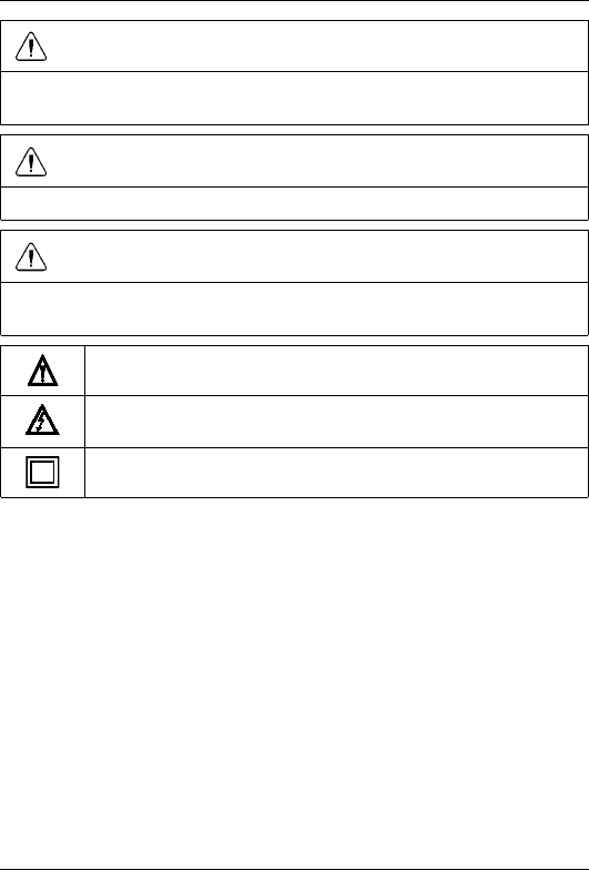
This symbol, adjacent to another symbol or terminal, indicates that
the user must refer to the manual for further information.
This symbol, adjacent to a terminal, indicates that, under normal
use, hazardous voltages may be present.
Double insulation.
#T559825; r.8008/8011; en-US 5

3 Introduction
Thank you for choosing a Flir CM83 clamp meter.
This device is shipped fully tested and calibrated and, with proper use, will pro-
vide years of reliable service.
3.1 Key features
• 10 000-count digital display.
• Active backlit, large-scale display.
• Analog bar graph.
• True RMS reading in AC and AC+DC mode.
• Torch lightening when clamping.
• Auto AC/DC 1000 A capability and selection.
• Auto AC/DC 1000 V capability and selection.
• Auto resistance/continuity/diode selection.
• Power and power factor measurement.
• Total harmonic distortion and 1 to 25 harmonics.
• Phase rotation Indication.
• 100 kΩ resistance capability.
• VoltSense (none-contact voltage).
• Frequency counter.
• Capacitance capability.
• Temperature function.
• Smart data hold.
• Peak hold.
• In-rush current.
• DCA auto-zeroing key.
• Minimum/maximum hold.
• Low-pass filter.
• Auto power off.
• Up to 42 mm diameter (1000 MCM) conductor.
• Bus bar size 62 mm × 12 mm (2.4″ × 0.5″).
• 1.2 m (4′) drop-proof.
• Convenient battery cover.
• CAT. IV 600 V /CAT. III 1000 V standard.
#T559825; r.8008/8011; en-US 6
4 Description
4.1 Meter parts
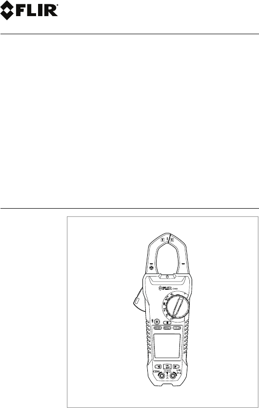
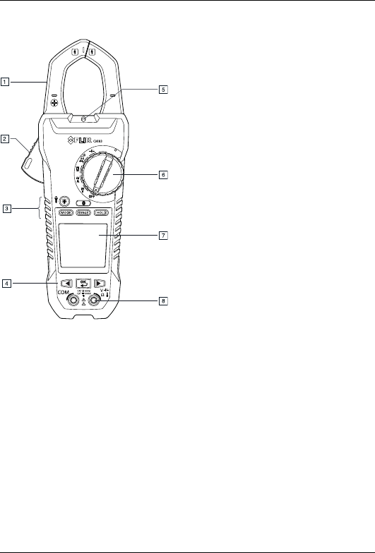
Figure 4.1 Front view
1. Clamp jaw.
2. Jaw opening trigger.
3. Function buttons, see section 4.3 Function buttons, page 9.
4. Navigation buttons.
5. Work light.
6. Function switch, see section 4.2 Function switch, page 8.
7. LCD display.
8. Probe/thermocouple terminals.
#T559825; r.8008/8011; en-US 7
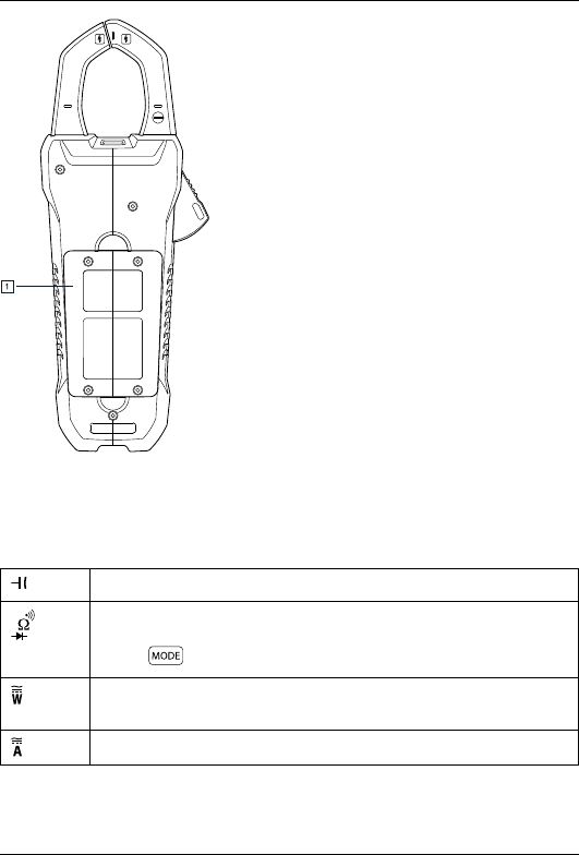
4 Description
Figure 4.2 Rear view
1. Battery compartment.
4.2 Function switch
The meter can measure capacitance through the probe inputs.
The meter can measure resistance, continuity, or diode polarity
through the probe inputs. The type of measurement is selected
by the button.
The meter can measure power through the probe inputs and the
clamp jaws.
The meter can measure current through the clamp jaws.
#T559825; r.8008/8011; en-US 8
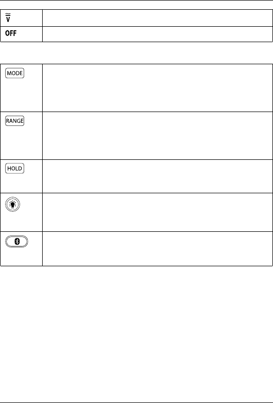
4 Description
The meter can measure voltage through the probe inputs.
The meter is in full power-saving mode.
4.3 Function buttons
• Use the button to select Auto select or Manual select mode,
see section 5.2 Auto/Manual select mode, page 12.
• In Manual select mode, press the button to select the operat-
ing mode.
• Use the button to select Auto range or Manual range mode,
see section 5.3 Auto/Manual range mode, page 13.
• In Manual range mode, press the button to change the range
(scale).
Press the button to toggle between Normal and Hold mode. In
Hold mode, the display freezes the last reading and continues to
display this value.
• Press the button to enable/disable the display backlight.
• Press and hold the button for 2 seconds to enable/disable the
work light.
Press the button to enable/disable MeterLink (Bluetooth) commu-
nication, see section 5.11 Streaming measurement data using
Bluetooth, page 24.
#T559825; r.8008/8011; en-US 9
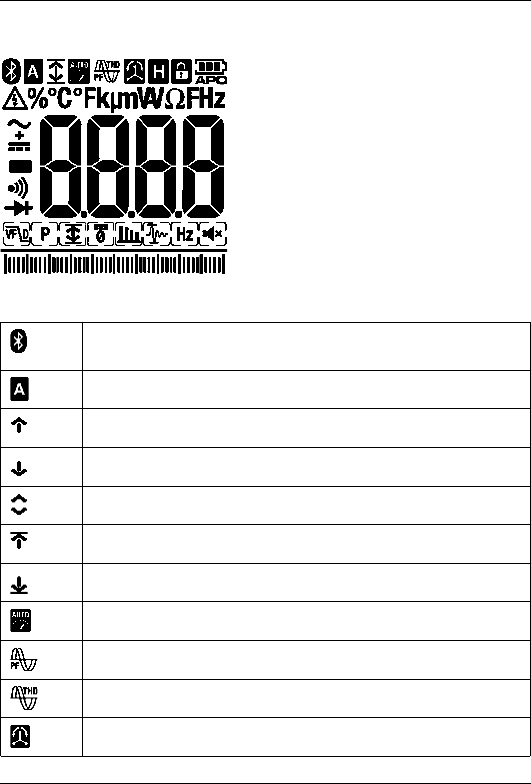
4 Description
4.4 Display icons and indicators
Figure 4.3 Display
Indicates that MeterLink (Bluetooth) communication is active, see
section 5.2 Auto/Manual select mode, page 12.
Indicates that the meter is in Auto select mode.
Indicates that the meter is displaying maximum reading values.
Indicates that the meter is displaying minimum reading values.
Indicates that the meter is displaying the average reading.
Indicates that the meter is displaying peak maximum values.
Indicates that the meter is displaying peak minimum values.
Indicates that the meter is in Auto range mode.
Indicates that the meter is in Power factor mode.
Indicates that the meter displays the total harmonic distortion.
Indicates that the meter is in Phase rotation mode.
#T559825; r.8008/8011; en-US 10
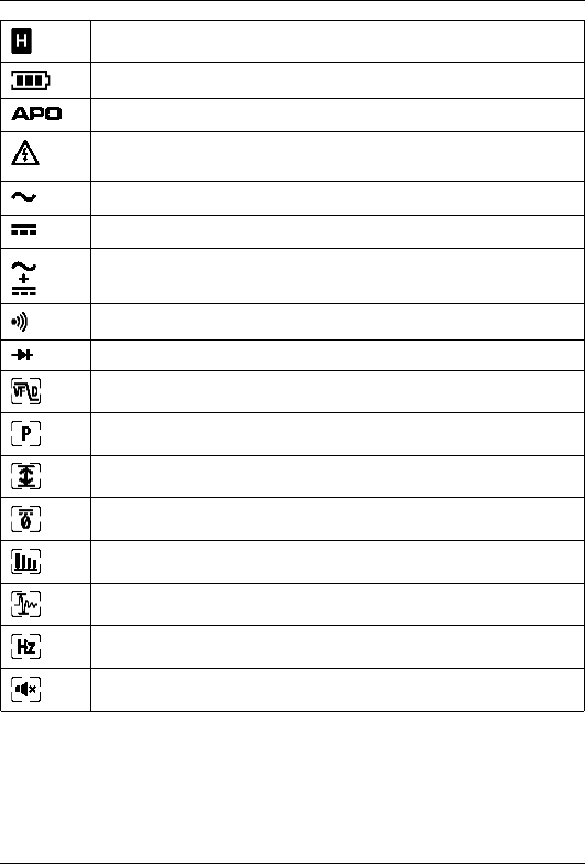
4 Description
Indicates that the meter is in Hold mode.
Indicates the battery voltage status.
Indicates that the auto power off function is enabled.
Indicates that the measured voltage is greater than 30 V DC or
AC RMS.
Indicates that the meter is measuring AC current or voltage.
Indicates that the meter is measuring DC current or voltage.
Indicates that the meter is measuring AC+DC current or voltage.
Indicates that the continuity function is active.
Indicates that the diode test function is active.
LPF mode icon.
Peak mode icon.
Min/Max/Avg mode icon.
DC Zero mode icon.
Harmonic Distortion icon.
In-rush current mode icon.
Frequency mode icon.
Silent mode icon.
4.4.1 Out-of-range warning
If the input is out-of-range, OL is displayed.
#T559825; r.8008/8011; en-US 11
5 Operation
Note
Before operating the device, you must read, understand, and follow all in-
structions, dangers, warnings, cautions, and notes.
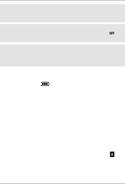
Note
When the meter is not in use, the function switch should be set to the
position.
Note
When connecting the probe leads to the device under test, connect the nega-
tive lead before connecting the positive lead. When removing the probe
leads, remove the positive lead before removing the negative lead.
5.1 Powering the meter
1. Set the function switch to any position to switch on the meter.
2. If the battery indicator shows that the battery voltage is low or if the me-
ter does not power on, replace the battery. See section 6.2 Battery replace-
ment, page 25.
5.1.1 Auto power off
The meter enters sleep mode after 30 minutes of inactivity. The meter beeps
three times 15 seconds before powering off. Press any button or turn the function
switch to prevent the meter from powering off. The auto power off time-out is then
reset.
5.2 Auto/Manual select mode
In Auto select mode, the meter attempts to automatically select the proper oper-
ating mode (e.g., AC, DC, or AC+DC measurement) based on the input signal. In
Manual select mode, the desired operating mode is selected manually.
Auto select mode is the default mode of operation. When a new function is se-
lected with the function switch, the starting mode is Auto select and the indi-
cator is displayed.
#T559825; r.8008/8011; en-US 12
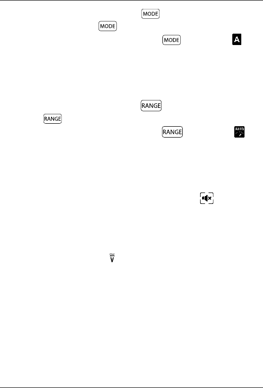
5 Operation
• To enter Manual select mode, press the button. To manually select the
operating mode, press the button repeatedly.
• To enter Auto select mode, press and hold the button until the indi-
cator is displayed.
5.3 Auto/Manual range mode
In Auto range mode, the meter automatically selects the most appropriate meas-
urement scale. In Manual range mode, the desired range (scale) is set manually.
• To enter Manual range mode, press the button. To change the range,
press the button repeatedly until the desired range is displayed.
• To enter Auto range mode, press and hold the button until the indi-
cator is displayed.
5.4 Silent mode
In Silent mode, the alert beeper is disabled. Silent mode does not affect the con-
tinuity beeper.
1. Use the navigation buttons to select the Silent mode icon , see section
5.5.3.1 Selecting the mode, page 15.
5.5 Voltage and current measurements
5.5.1 Basic voltage measurements
1. Set the function switch to the position.
2. Insert the black probe lead into the negative COM terminal and the red probe
lead into the positive V terminal.
3. Connect the probe leads in parallel to the part under test.
4. Read the voltage value on the display.
#T559825; r.8008/8011; en-US 13
5 Operation
5.5.2 Basic current measurements
WARNING
Do not measure the current on a circuit when the voltage increases to more
than 600 V. This can cause damage to the instrument and can cause injury to
persons.
Note
If the measured voltage is greater than 30 V DC or AC RMS, the indicator
is displayed.
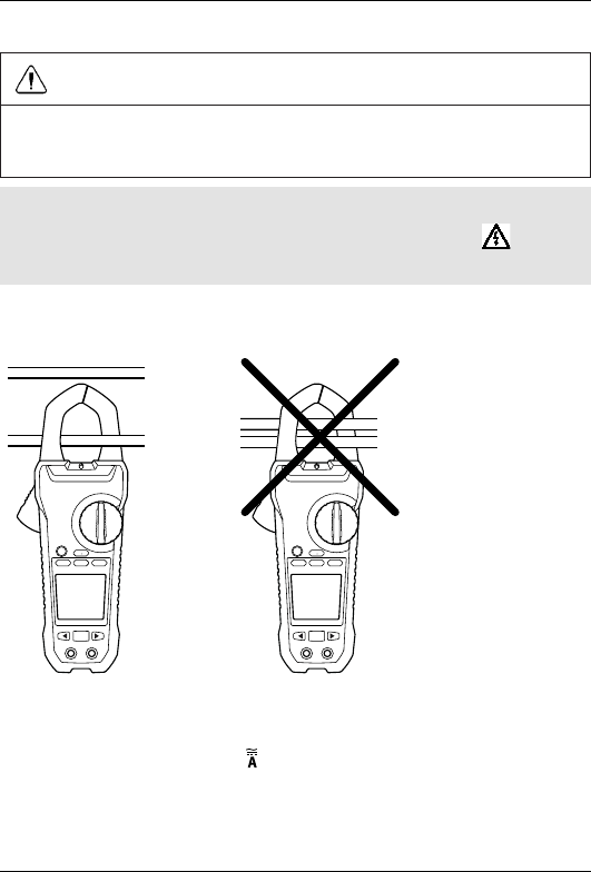
When measuring current using the clamp jaws, only one conductor should be en-
closed by the jaws—refer to Figure 5.1.
Figure 5.1 Correct and incorrect setup
1. Ensure that the probe/thermocouple leads are disconnected from the meter.
2. Set the function switch to the position.
3. Press the trigger to open the clamp jaws. Fully enclose one conductor—refer
to Figure 5.1. For optimum results, center the conductor in the jaws.
4. Read the current value on the display.
#T559825; r.8008/8011; en-US 14
5 Operation
5.5.3 Extended functionality
In addition to the basic voltage and current measurements, the meter can be set
to different modes for extended functionality.
5.5.3.1 Selecting the mode
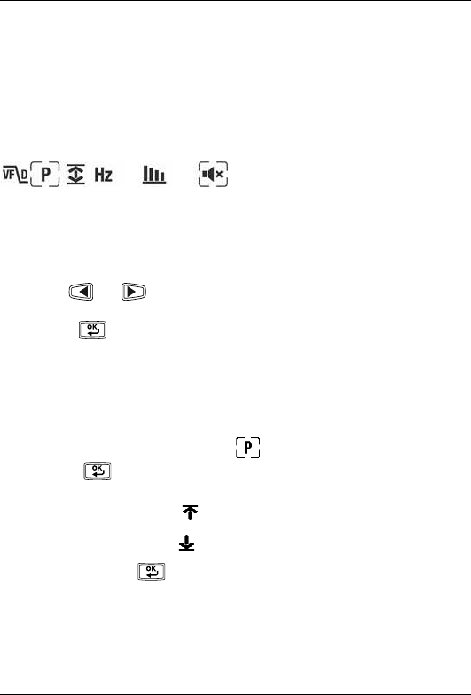
The mode icons applicable for the selected measurement type are displayed in
the lower part of the display. When a mode is enabled, the icon is framed.
Figure 5.2 Mode icons (AC voltage measurements): Peak mode and Silent
mode are enabled
The navigation buttons are used to select a mode icon and to enable/disable a
mode:
• Use the and navigation buttons to navigate to a mode icon. The cur-
rently selected icon will flash.
• Press the button to enable/disable the selected (flashing) mode.
5.5.3.2 Peak mode
In Peak mode, the meter captures and displays the positive and negative peak
values, and updates only when a higher/lower value is registered. Peak mode is
available when measuring AC current or voltage in Manual select mode.
1. Use the navigation buttons to select and enable Peak mode.
2. Press the button to toggle between the display of Peak Max and Peak
Min.
• In Peak Max mode, the indicator is displayed.
• In Peak Min mode, the indicator is displayed.
3. Press and hold the button to disable Peak mode.
#T559825; r.8008/8011; en-US 15
5 Operation
5.5.3.3 In-rush current mode
In In-rush current mode, the meter displays the highest current reading in the first
100 ms after the trigger point. In-rush current mode is available when measuring
AC current in Manual select mode.
1. Use the navigation buttons to select and enable In-rush current mode.
Note
If the in-rush current under testing may be more than 100 A AC, manually set
the range to 600 A/1000 A before activating the in-rush current, see section
5.3 Auto/Manual range mode, page 13.
5.5.3.4 DC Zero mode
The DC zero feature removes offset values and improves the accuracy for DC
current measurements. DC Zero mode is available when measuring DC or AC
+DC current in Manual select mode.
1. Ensure that there is no conductor in the clamp jaws.
2. Use the navigation buttons to select and enable DC Zero mode.
5.5.3.5 Frequency mode
In Frequency mode, the meter measures and displays the frequency. Frequency
mode is available when measuring AC current or voltage in Manual select mode.
1. Use the navigation buttons to select and enable Frequency mode.
5.5.3.6 Min/Max/Avg mode
In Min/Max/Avg mode, the meter captures and displays the minimum or maxi-
mum values and updates only when a higher/lower value is registered. The meter
can also calculate the average of the minimum and maximum value. Min/Max/
Avg mode is available for all measurement types.
1. Use the navigation buttons to select and enable Min/Max/Avg mode.
2. Press the button repeatedly to cycle through the minimum, maximum,
and average reading displays. The corresponding icons are displayed: ,
, or .
#T559825; r.8008/8011; en-US 16
5 Operation
3. Press and hold the button to disable Min/Max/Avg mode.
5.5.3.7 Harmonic Distortion mode
In Harmonic Distortion mode, the meter displays the distortion percentage value
for the first 25 harmonics as well as the total harmonic distortion. Harmonic Dis-
tortion mode is available when measuring AC current or voltage in Manual select
mode.
The harmonic distortion is expressed as Hn= (RMS of an individual harmonic n
)/(RMS of the fundamentals) × 100%.
1. Use the navigation buttons to select and enable Harmonic Distortion
mode.
2. While in Harmonic Distortion mode, use the and navigation buttons
to navigate through the individual and total harmonic data.
3. When the total harmonic distortion is displayed, the indicator appears in
the upper part of the display.
4. Press and hold the button to disable Harmonic Distortion mode.
5.5.3.8 LPF mode
In LPF mode, high-frequency noise is eliminated from the voltage measurement
by a low-pass filter (LPF). LPF mode is intended for measurements on variable-
frequency drives (VFDs). LPF mode is available when measuring AC current or
voltage in Manual select mode.
1. Use the navigation buttons to select and enable LPF mode.
5.6 Power measurements
5.6.1 Single-phase power measurements
1. Set the function switch to the position.
2. Insert the black probe lead into the negative COM terminal and the red probe
lead into the positive W terminal.
#T559825; r.8008/8011; en-US 17
5 Operation
3. Press the trigger to open the clamp jaws. Fully enclose one conductor—refer
to Figure 5.1. For optimum results, center the conductor in the jaws.
Note
The + symbol on the jaw should be directed toward the power source.
4. Connect the probe leads in parallel to the part under test.
5. Read the active power value on the display.
• If the value is displayed without a sign, the power is flowing from the
power source to the load.
• If the value is displayed with a minus sign (–), the power is flowing from
the power load to the source.
6. To measure and display the power factor, press the button repeatedly
until the indicator is displayed.
7. Read the power factor value on the display.
• If the value is displayed without a sign, the phase of the current signal is
lagging behind the voltage signal (inductive load).
• If the value is displayed with a minus sign (–), the phase of the current sig-
nal is leading the voltage signal (capacitive load).
8. To return to active power measurements, press the button repeatedly
until neither the nor the indicator is displayed.
If an overload occurs, the following is displayed:
•OL.V: Voltage overload.
•OL.A: Current overload.
•OL: Both voltage and current overload.
•OL.W: Active power overload.
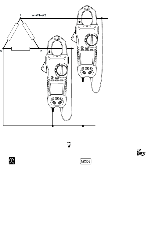
5.6.2 Three-phase power measurements
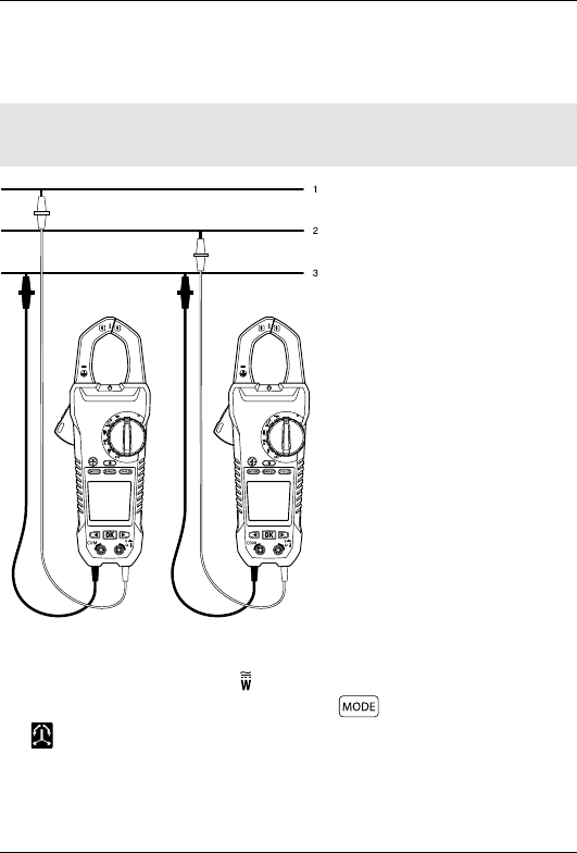
5.6.2.1 Three-phase three-wire balanced/unbalanced
The power of a three-phase three-wire wye (star) configuration is measured in
two steps, in accordance with Figure 5.3. The total power is the sum of the two
measurements: W=W1+W2.
#T559825; r.8008/8011; en-US 18
5 Operation
Figure 5.3 Three-phase three-wire measurement
1. Set the function switch to the position.
2. Ensure that the meter is set to active power measurement. If the or the
indicator is displayed, press the button repeatedly until none of
these indicators are displayed.
3. Take two measurements of the active power, in accordance with Figure 5.3.
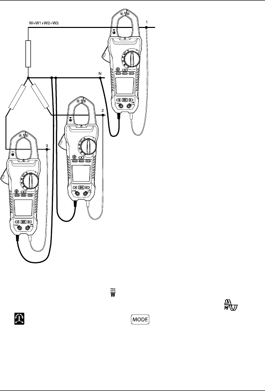
5.6.2.2 Three-phase four-wire balanced/unbalanced
The power of a three-phase four-wire configuration is measured in three steps,
accordance with Figure 5.4. The total power is the sum of the three measure-
ments: W=W1+W2+W3.
#T559825; r.8008/8011; en-US 19
5 Operation
Figure 5.4 Three-phase four-wire measurement
1. Set the function switch to the position.
2. Ensure that the meter is set to active power measurement. If the or the
indicator is displayed, press the button repeatedly until none of
these indicators are displayed.
3. Take three measurements of the active power, in accordance with Figure
5.4.
#T559825; r.8008/8011; en-US 20
5 Operation
5.6.3 Phase rotation
With the meter set to Phase rotation mode, it is possible to determine the phase
rotation for a three-wire system.
Note
The system frequency must be stable.
Figure 5.5 Phase rotation
1. Set the function switch to the position.
2. Enter Phase rotation mode by pressing the button repeatedly until the
indicator is displayed.
3. Connect the red test lead to the presumed phase line 1 and the black test
lead to the presumed phase line 3.
#T559825; r.8008/8011; en-US 21
5 Operation
4. One of the following results is displayed:
•OLU flashes if the voltage is >1000 V.
•LoU flashes if the voltage is <30 V.
•outF flashes if the frequency is >65 Hz or <45 Hz.
• If normal, L1 flashes for about 3 seconds. Then L2 is displayed.
5. Move the red test lead to the presumed phase line 2.
6. One of the following results is displayed:
•123 indicates clockwise or forward rotation, which means that the pre-
sumed phase line 1 is ahead of the presumed phase line 2.
•321 indicates counterclockwise or reversed rotation, which means that
the presumed phase line 2 is ahead of the presumed phase line 1.
•- - - means that the meter is unable to determine the results.
5.7 Resistance measurements
WARNING
Do not do diode, resistance or continuity tests before you have removed the
power from the capacitors and from a device during a test. Injury to persons
can occur.
1. Set the function switch to the position.
2. Ensure that the meter is set to resistance measurement. If the or the
indicator is displayed, press the button repeatedly until none of these
indicators are displayed.
3. Insert the black probe lead into the negative COM terminal and the red probe
lead into the positive Ωterminal.
4. Touch the tips of the probe across the circuit or component under test.
5. Read the resistance value on the display.
5.8 Capacitance measurements
WARNING
Do not do diode, resistance or continuity tests before you have removed the
power from the capacitors and from a device during a test. Injury to persons
can occur.
#T559825; r.8008/8011; en-US 22
5 Operation
1. Set the function switch to the position.
2. Insert the black probe lead into the negative COM terminal and the red probe
lead into the positive terminal.
3. Touch the tips of the probe across the part under test.
4. Read the capacitance value on the display.
Note
For very large capacitance values, it may take several minutes for the
measurement to settle and the final reading to stabilize.
5.9 Continuity test
WARNING
Do not do diode, resistance or continuity tests before you have removed the
power from the capacitors and from a device during a test. Injury to persons
can occur.
1. Set the function switch to the position.
2. Insert the black probe lead into the negative COM terminal and the red probe
lead into the positive Ωterminal.
3. Use the button to select continuity measurement. The indicator will
be displayed.
4. Touch the tips of the probe across the circuit or component under test.
5. If the resistance is less than 30 Ω, the meter will beep.
5.10 Diode test
WARNING
Do not do diode, resistance or continuity tests before you have removed the
power from the capacitors and from a device during a test. Injury to persons
can occur.
1. Set the function switch to the position.
2. Insert the black probe lead into the negative COM terminal and the red probe
lead into the positive Ωterminal.
#T559825; r.8008/8011; en-US 23

5 Operation
3. Use the button to select the diode test function. The indicator will
be displayed.
4. Touch the tips of the probe across the diode or semiconductor junction under
test. Make a note of the value on the display.
5. Reverse the polarity of the probe, by interchanging the probe test locations.
6. Touch the tips of the probe across the diode or semiconductor junction under
test. Make a note of the new value on the display.
7. The diode or semiconductor junction can be evaluated as follows:
• If one of the readings displays a value (typically 0.400 V or 0.900 V) and
the other reading displays OL, the component is good.
• If both readings display OL, the component is open.
• If both readings are very small or 0, the component is shorted.
5.11 Streaming measurement data using Bluetooth
5.11.1 General
Some IR cameras from Flir Systems support Bluetooth communication, and to
those cameras you can stream measurement data from the meter. The data is
then merged into the result table in the IR image.
Streaming measurement data is a convenient way to add important information
to an IR image. For example, when identifying an overheated cable connection,
you may want to know the current in that cable.
5.11.2 Procedure
1. Pair the IR camera with the instrument. Refer to the camera manual for infor-
mation on how to pair Bluetooth devices.
2. Turn on the camera.
3. Turn on the meter.
4. Press the on the meter to enable Bluetooth.
5. Choose the variable that you want to use (voltage, current, resistance, etc.).
Results from the meter will now automatically be displayed in the result table
in the top left corner of the IR camera screen.
#T559825; r.8008/8011; en-US 24
6 Maintenance
6.1 Cleaning and storage
Clean the meter with a damp cloth and mild detergent; do not use abrasives or
solvents.
If the meter is not to be used for an extended period, remove the batteries and
store them separately.
6.2 Battery replacement
1. To avoid electrical shock, disconnect the meter if connected to a circuit, re-
move the probe/thermocouple leads from the terminals, and set the function
switch to the position before attempting to replace the batteries.
2. Unscrew and remove the battery compartment cover.
3. Replace the six standard AAA batteries, observing correct polarity.
4. Secure the battery compartment cover.
6.2.1 Disposal of electronic waste
As with most electronic products, this equipment must be disposed of in an envi-
ronmentally friendly way, and in accordance with existing regulations for elec-
tronic waste.
Please contact your Flir Systems representative for more details.
#T559825; r.8008/8011; en-US 25

7 Technical specifications
7.1 Model specifications
AC A
Ranges 100.00 A,
600.0 A
Resolution 0.01 A
Basic accuracy ±(1.5% + 5 digits) at 50–500 Hz
Conversion type: average sensing
RMS indicating • AC+DC
• True RMS
DC A
Ranges 100.00 A, 600.0 A
Resolution 0.01 A
Basic accuracy ±(1.5% + 5 digits)
AC+DC A
Ranges 100.00 A, 600.0 A
Resolution 0.01 A
Basic accuracy Same as AC A + (1.5% + 5 digits)
AC V
Ranges 100.00–1000 V
Resolution 0.01 V
Basic accuracy ±(1.0% + 5 digits) at 50–500 Hz
Input impedance 3.5 MΩ
Overload protection 1000 V RMS
Conversion type: average sensing
RMS indicating
AC+DC true RMS
DC V
#T559825; r.8008/8011; en-US 26

7 Technical specifications
Ranges 100.00–1000 V
Resolution 0.01 V
Basic accuracy ±(0.7% + 2 digits)
Input impedance 3.5 MΩ
Overload protection 1000 V RMS
AC+DC V
Ranges 100.00–1000 V
Resolution 0.01 V
Basic accuracy ±(1.0% + 5 digits)
Input impedance 3.5 MΩ
Overload protection 1000 V RMS
Watts
Ranges 10–600 kW
Resolution 1 W
Basic accuracy ±(2.5% + 5 digits)
Power factor
Ranges –1.00 to 1.00
Resolution 0.01
Basic accuracy ±3°
Total harmonic distortion
Ranges 0.1%~100.0%
Resolution 0.1%
Basic accuracy ±(3.0% + 10 digits)
Harmonics
Ranges 0.1–100.0%
#T559825; r.8008/8011; en-US 27

7 Technical specifications
Resolution 0.1%
Basic accuracy • ±(5.0% + 10 digits) for order 1–12
• ±(10.0% + 10 digits) for order 13–
25
Ohms
Ranges 1.0000 kΩ, 10.00 kΩ, 100.00 kΩ
Resolution 0.01 Ω
Accuracy ±( 1.0% + 3 digits)
Overload protection 1000 V RMS
Continuity beeper
<30 Ω, 2 kHz tone buzzer
Diode test
Open circuit voltage ±1.8 V max
Capacitance
Ranges 400.0 μF, 4.000 mF
Resolution 0.1 μF
Basic accuracy ±(1.9% + 8 digits)
Overload protection 1000 V RMS
Frequency counter
Ranges 20.0 Hz to 10 kHz
Resolution 0.1 Hz
Basic accuracy ±(0.5% + 3 digits)
Overload Protection AC/DC 600 A, AC/DC 1000 A
#T559825; r.8008/8011; en-US 28

7 Technical specifications
7.2 System specifications
Dimensions 49 mm × 100 mm × 262 mm (1.9″ ×
3.9″ × 10.3″)
Weight 0.59 kg (1.29 lb.), including batteries
Battery life 200 hours
Battery type 6 × AAA (LR03)
Agency approvals FCC Class B, CE, UL/CSA, GSA, S-
JQA
7.3 Environmental specifications
Operating temperature 0 to 50°C (32 to 122°F)
Storage temperature –20 to 60°C (–4 to 140°F)
Operating humidity Maximum 90% up to 35°C (95°F),
decreasing linearly to 60% at 45°C
(113°F)
Storage humidity 90% maximum
Operational altitude 2000.0 m (6562′)
Electromagnetic compatibility EMC EN6 1326-1
Vibration Random vibration per MIL-PRF-
28800f Class 2 (5– 55 Hz, 3g
maximum).
Shock 5 m (16.4′) drop per IEC/EN 61010-
1, 2nd edition
#T559825; r.8008/8011; en-US 29

8 Flir Global Limited Lifetime Warranty
A qualifying FLIR Test and Measurement product (the
“Product”) purchased either directly from FLIR Commer-
cial Systems Inc and affiliates (FLIR) or from an author-
ized FLIR distributor or reseller that Purchaser registers
on-line with FLIR is eligible for coverage under FLIR’s Lim-
ited Lifetime Warranty, subject to the terms and conditions
in this document. This warranty only applies to purchases
of Qualifying Products (see below) purchased and manu-
factured after April 1, 2013.
PLEASE READ THIS DOCUMENT CAREFULLY; IT CON-
TAINS IMPORTANT INFORMATION ABOUT THE PROD-
UCTS THAT QUALIFY FOR COVERAGE UNDER THE
LIMITED LIFETIME WARRANTY, PURCHASER’S OBLI-
GATIONS, HOW TO ACTIVATE THE WARRANTY, WAR-
RANTY COVERAGE, AND OTHER IMPORTANT TERMS,
CONDITIONS, EXCLUSIONS AND DISCLAIMERS.
1. PRODUCT REGISTRATION. To qualify for FLIR’s Lim-
ited Lifetime Warranty, Purchaser must fully register the
Product directly with FLIR on-line at http://www.flir.com
within Sixty (60) DAYS of the date the Product was pur-
chased by the first retail customer (the “Purchase Date”).
Qualifying PRODUCTS THAT ARE NOT REGISTERED
ON-LINE WITHIN SIXTY (60) DAYS OF THE PURCHASE
DATE WILL HAVE A LIMITED ONE YEAR WARRANTY
FROM DATE OF PURCHASE.
2. QUALIFYING PRODUCTS. Upon registration, Test and
Measurment products that qualify for coverage under
FLIR’s Limited Lifetime Warranty are:
• Flir CM78
• Flir CM83
• Flir DM93
• Flir MR77
• Flir VP50
• Flir VP52
• Flir VS70
3. WARRANTY PERIODS. For purposes of the The Lim-
ited Lifetime Warranty, Lifetime is defined as seven years
(7)after the product is no longer manufactured, or ten
years (10) from date of purchase whichever is greater.
This Warranty is only applicable to the original owner of
the Products.
Any Product that is repaired or replaced under warranty is
covered under this 2-5-10 Limited Warranty for one hun-
dred eighty days (180) days from the date of return ship-
ment by FLIR or for the remaining duration of the
applicable Warranty Period, whichever is longer.
4. LIMITED WARRANTY. In accordance with the terms
and conditions of thisLimited Lifetime Warranty, and ex-
cept as excluded or disclaimed in this document, FLIR
warrants, from the Purchase Date, that all fully registered
Products will conform to FLIR’s published Product specifi-
cations and be free from defects in materials and work-
manship during the applicable Warranty Period.
PURCHASER’S SOLE AND EXCLUSIVE REMEDY
UNDER THIS WARRANTY, AT FLIR’S SOLE DISCRE-
TION, IS THE REPAIR OR REPLACEMENT OF DEFEC-
TIVE PRODUCTS IN A MANNER, AND BY A SERVICE
CENTER, AUTHORIZED BY FLIR. IF THIS REMEDY IS
ADJUDICATED TO BE INSUFFICIENT, FLIR SHALL RE-
FUND PURCHASER’S PAID PURCHASE PRICE AND
HAVE NO OTHER OBLIGATION OR LIABILITY TO
BUYER WHATSOEVER.
5. WARRANTY EXCLUSIONS AND DISCLAIMERS.
FLIR MAKES NO OTHER WARRANTY OF ANY KIND
WITH RESPECT TO THE PRODUCTS. ALL OTHER
WARRANTIES, EXPRESS OR IMPLIED, INCLUDING
BUT NOT LIMITED TO IMPLIED WARRANTIES OF MER-
CHANTABILITY, FITNESS FOR A PARTICULAR PUR-
POSE (EVEN IF PURCHASER HAS NOTIFIED FLIR OF
ITS INTENDED USE FOR THE PRODUCTS), AND NON-
INFRINGEMENT ARE EXPRESSLY EXCLUDED FROM
THIS AGREEMENT.
THIS WARRANTY EXPRESSLY EXCLUDES ROUTINE
PRODUCT MAINTENANCE, AND SOFTWARE UP-
DATES. FLIR FURTHER EXPRESSLY DISCLAIMS ANY
WARRANTY COVERAGE FOR MANUALS, FUSES, DIS-
POSABLE BATTERIES, WHERE THE ALLEGED NON-
CONFORMITY IS DUE TO NORMAL WEAR AND TEAR
OTHER ALTERATION, MODIFICATION, REPAIR, AT-
TEMPTED REPAIR, IMPROPER USE, IMPROPER MAIN-
TENANCE, NEGLECT, ABUSE, IMPROPER STORAGE,
FAILURE TO FOLLOW ANY PRODUCT INSTRUCTIONS,
DAMAGE (WHETHER CAUSED BY ACCIDENT OR OTH-
ERWISE), OR ANY OTHER IMPROPER CARE OR
HANDING OF THE PRODUCTS CAUSED BY ANYONE
OTHER THAN FLIR OR FLIR’S EXPRESSLY AUTHOR-
IZED DESIGNEE.
THIS DOCUMENT CONTAINS THE ENTIRE WAR-
RANTY AGREEMENT BETWEEN PURCHASER AND
FLIR AND SUPERSEDES ALL PRIOR WARRANTY NE-
GOTIATIONS, AGREEMENTS, PROMISES AND
UNDERSTANDINGS BETWEEN PURCHASER AND
FLIR. THIS WARRANTY MAY NOT BE ALTERED WITH-
OUT THE EXPRESS WRITTEN CONSENT OF FLIR.
6. WARRANTY RETURN, REPAIR AND REPLACE-
MENT. To be eligible for warranty repair or replacement,
Purchaser must notify FLIR within thirty (30) days of dis-
covering of any apparent defect in materials or workman-
ship. Before Purchaser may return a Product for warranty
service or repair, Purchaser must first obtain a returned
material authorization (RMA) number from FLIR. To obtain
the RMA number Owner must provide an original proof of
purchase . For additional information, to notify FLIR of an
apparent defect in materials or workmanship, or to request
an RMA number, visit http://www.flir.com. Purchaser is
solely responsible for complying with all RMA instructions
provided by FLIR including but not limited to adequately
packaging the Product for shipment to FLIR and for all
packaging and shipping costs. FLIR will pay for returning
#T559825; r.8008/8011; en-US 30

8 Flir Global Limited Lifetime Warranty
to Purchaser any Product that FLIR repairs or replaces
under warranty.
FLIR reserves the right to determine, in its sole discretion,
whether a returned Product is covered under Warranty. If
FLIR determines that any returned Product is not covered
under Warranty or is otherwise excluded from Warranty
coverage, FLIR may charge Purchaser a reasonable han-
dling fee and return the Product to Purchaser, at Purchas-
er’s expense, or offer Purchaser the option of handling the
Product as a non-warranty return.
7. NON-WARRANTY RETURN. Purchase may request
that FLIR evaluate and service or repair a Product not cov-
ered under warranty, which FLIR may agree to do in its
sole discretion. Before Purchaser returns a Product for
non-warranty evaluation and repair, Purchaser must con-
tact FLIR by visiting http://www.flir.com to request an eval-
uation and obtain an RMA. Purchaser is solely
responsible for complying with all RMA instructions pro-
vided by FLIR including but not limited to adequately
packaging the Product for shipment to FLIR and for all
packaging and shipping costs. Upon receipt of an author-
ized non-warranty return, FLIR will evaluate the Product
and contact Purchaser regarding the feasibility of and the
costs and fees associated with Purchaser’s request. Pur-
chaser shall be responsible for the reasonable cost of
FLIR’s evaluation, for the cost of any repairs or services
authorized by Purchaser, and for the cost of repackaging
and returning the Product to Purchaser.
Any non-warranty repair of a Product is warranted for one
hundred eighty days (180) days from the date of return
shipment by FLIR to be free from defects in materials and
workmanship only, subject to all of the limitations, exclu-
sions and disclaimers in this document.
#T559825; r.8008/8011; en-US 31

A note on the technical production of this publication
This publication was produced using XML — the eXtensible Markup Language.
For more information about XML, please visit http://www.w3.org/XML/
A note on the typeface used in this publication
This publication was typeset using Linotype Helvetica™ World. Helvetica™ was
designed by Max Miedinger (1910–1980)
LOEF (List Of Effective Files)
T501025.xml; en-US; 8008; 2013-06-05
T505544.xml; en-US; 7912; 2013-05-31
#T559825; r.8008/8011; en-US 32

last page
Publ. No.: T559825
Commit: 8008
Head: 8011
Language: en-US
Modified: 2013-06-05
Formatted: 2013-06-05
Corporate Headquarters
Flir Systems, Inc.
27700 SW Parkway Ave.
Wilsonville, OR 97070
USA
Telephone: +1-503-498-3547
Website
http://www.flir.com
Customer support
http://support.flir.com