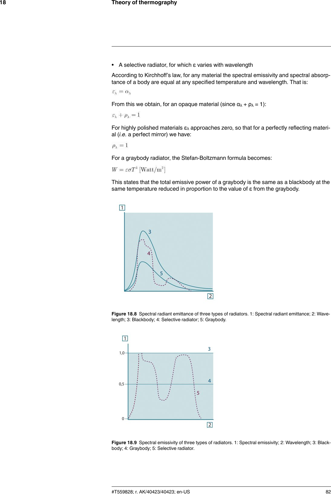
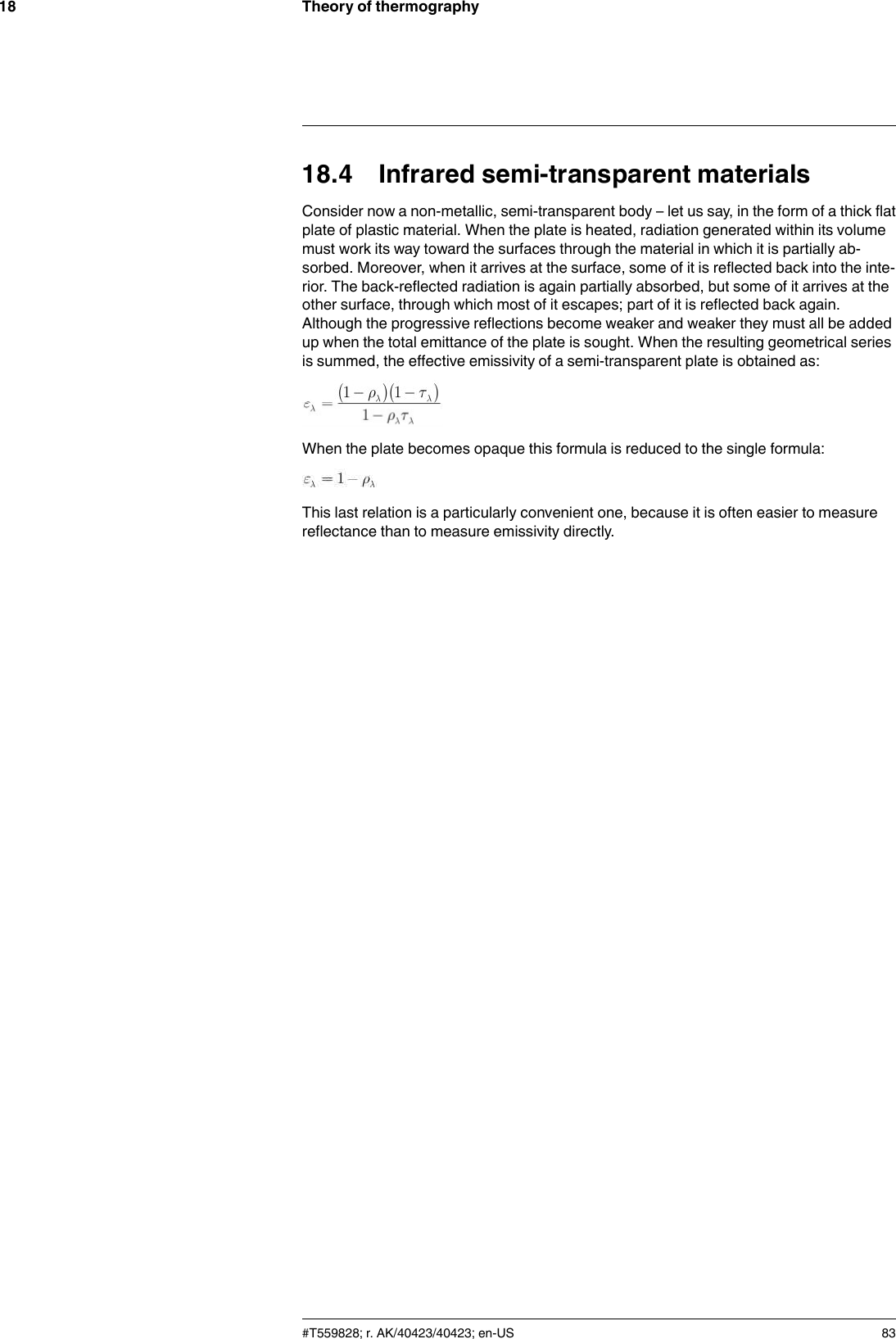
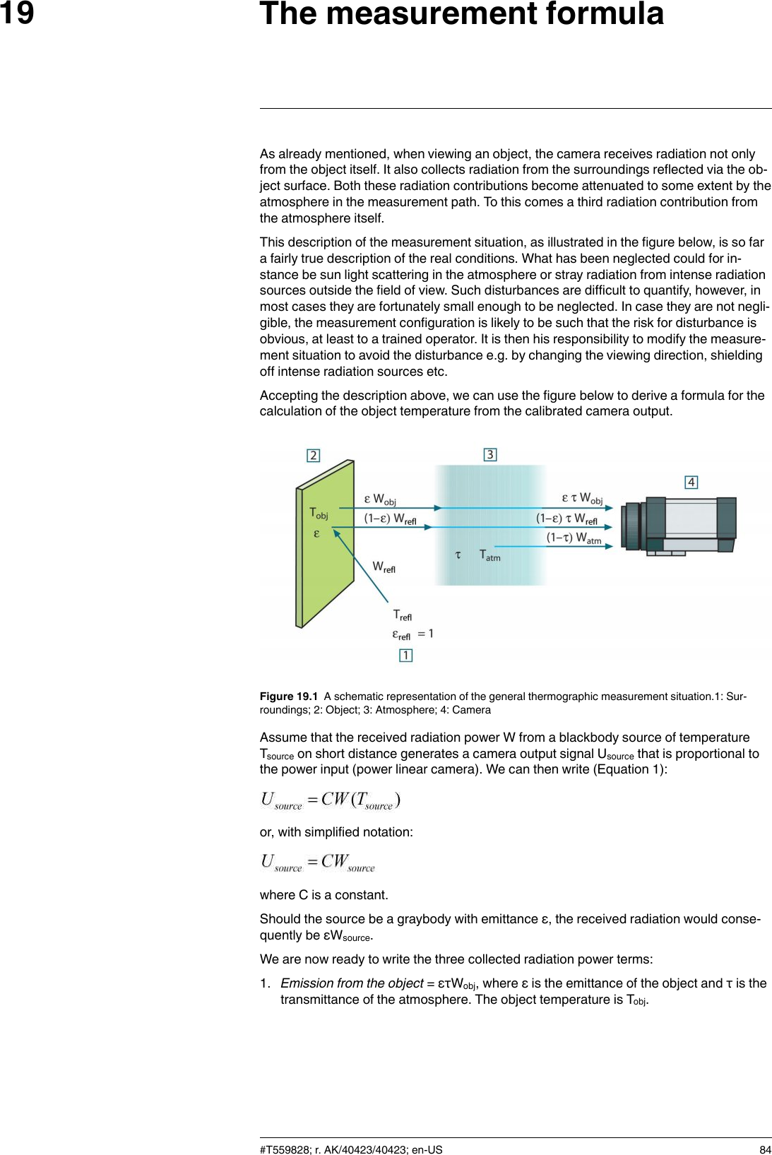
FLIR Systems FLIRE6390 Infrared Camera User Manual
FLIR Systems AB Infrared Camera
UserManual.wiki
>
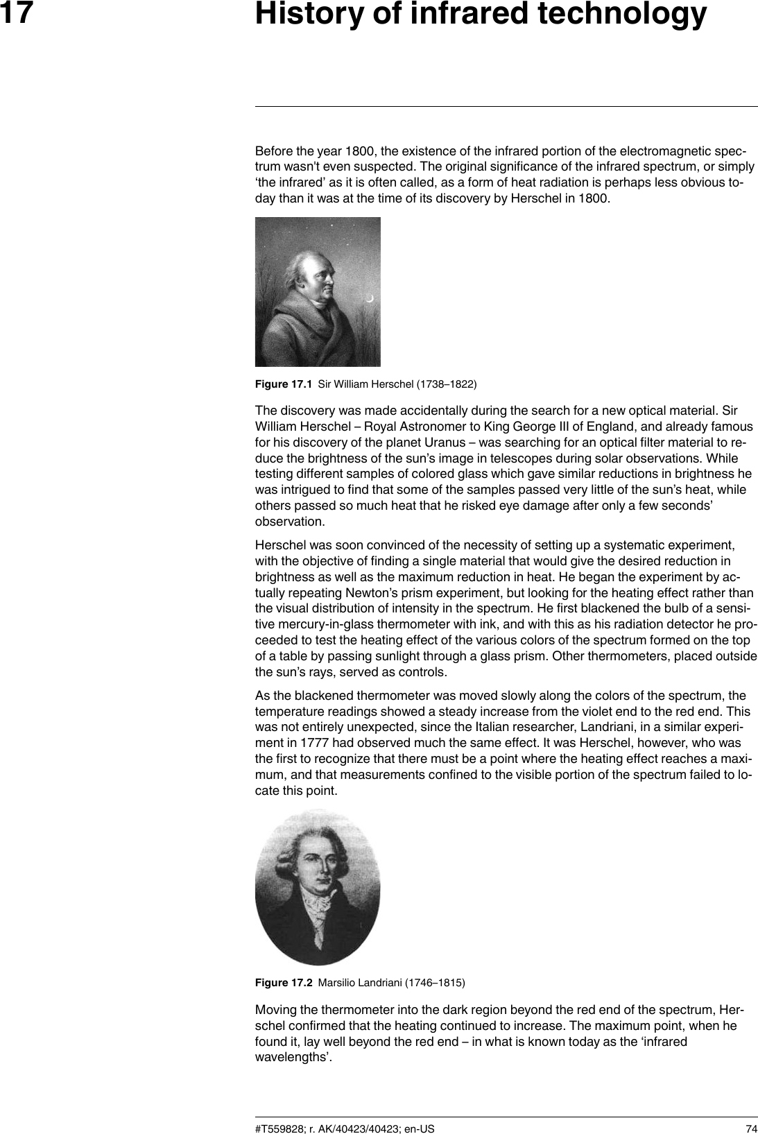
FLIR Systems
>
FLIRE6390 User Manual
User Manual
Navigation menu
Upload a User Manual
Namespaces
Wiki Guide
HTML
PDF
Info
Views
User Manual
Discussion / Help
Navigation


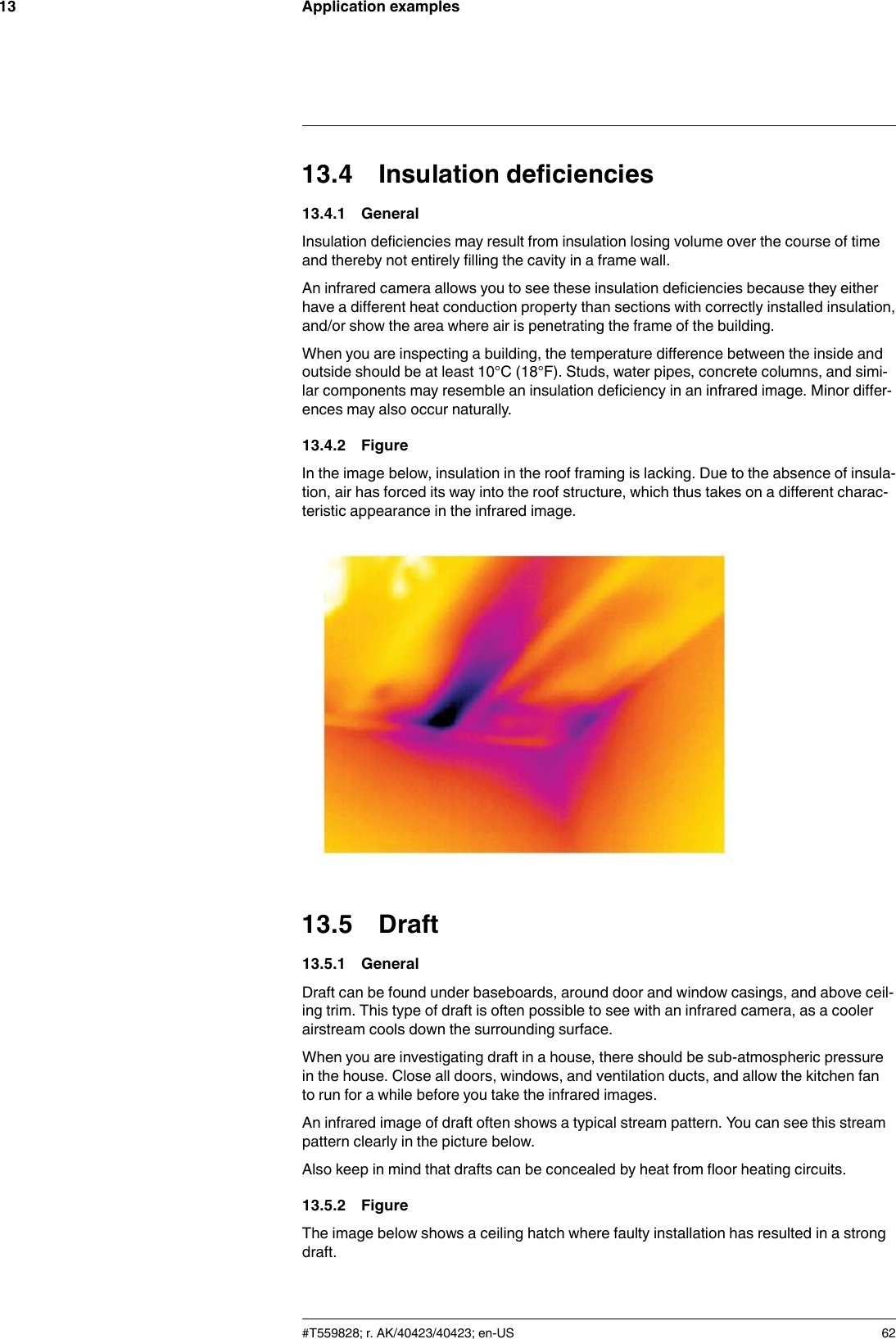
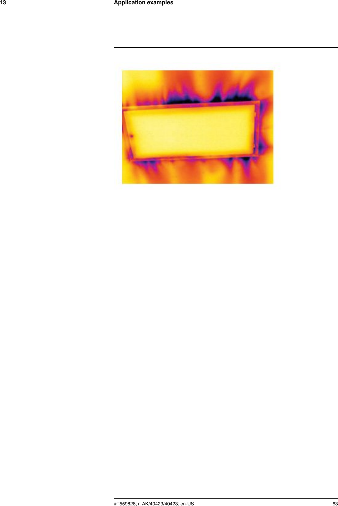
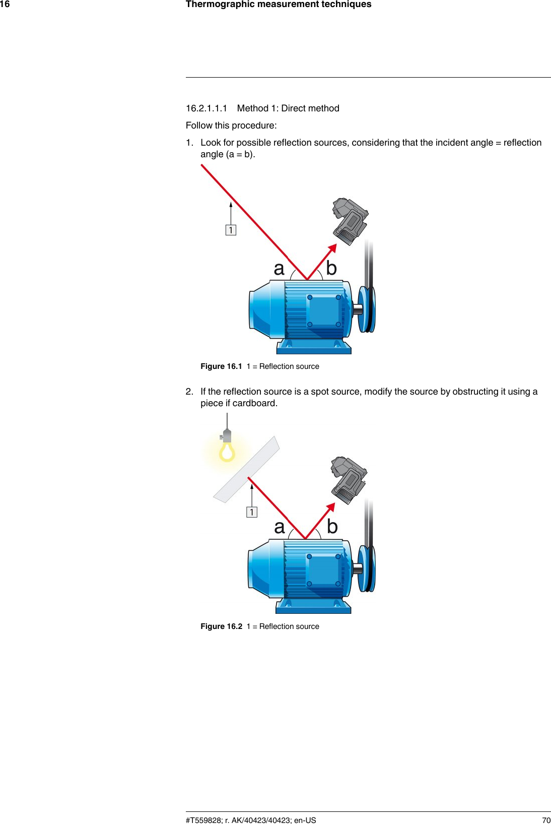
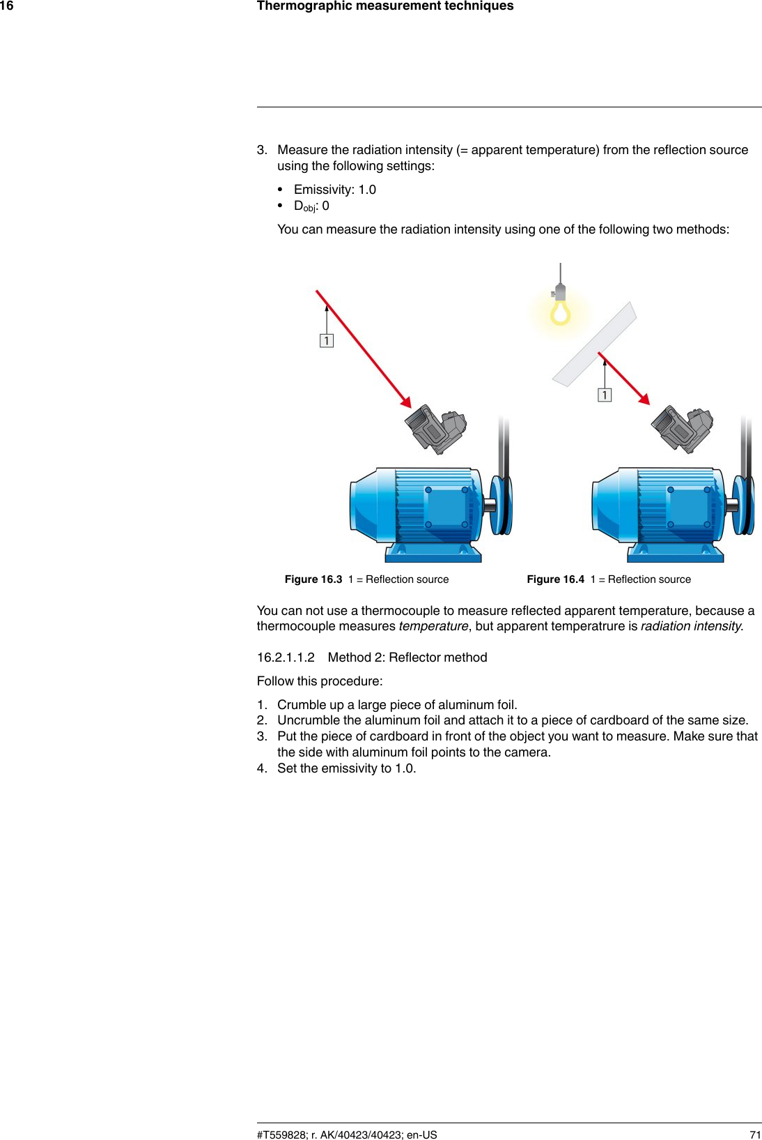
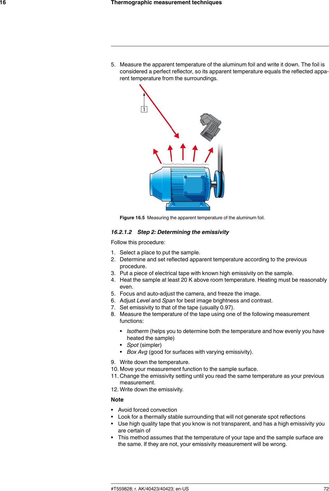
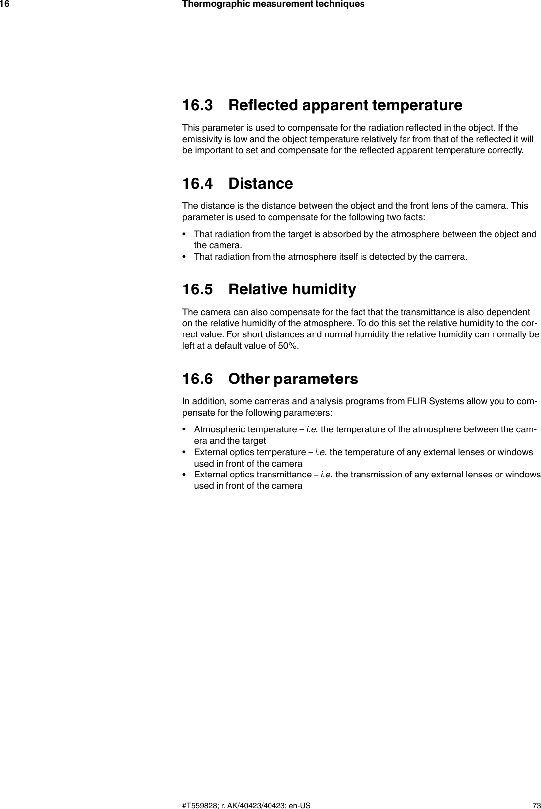
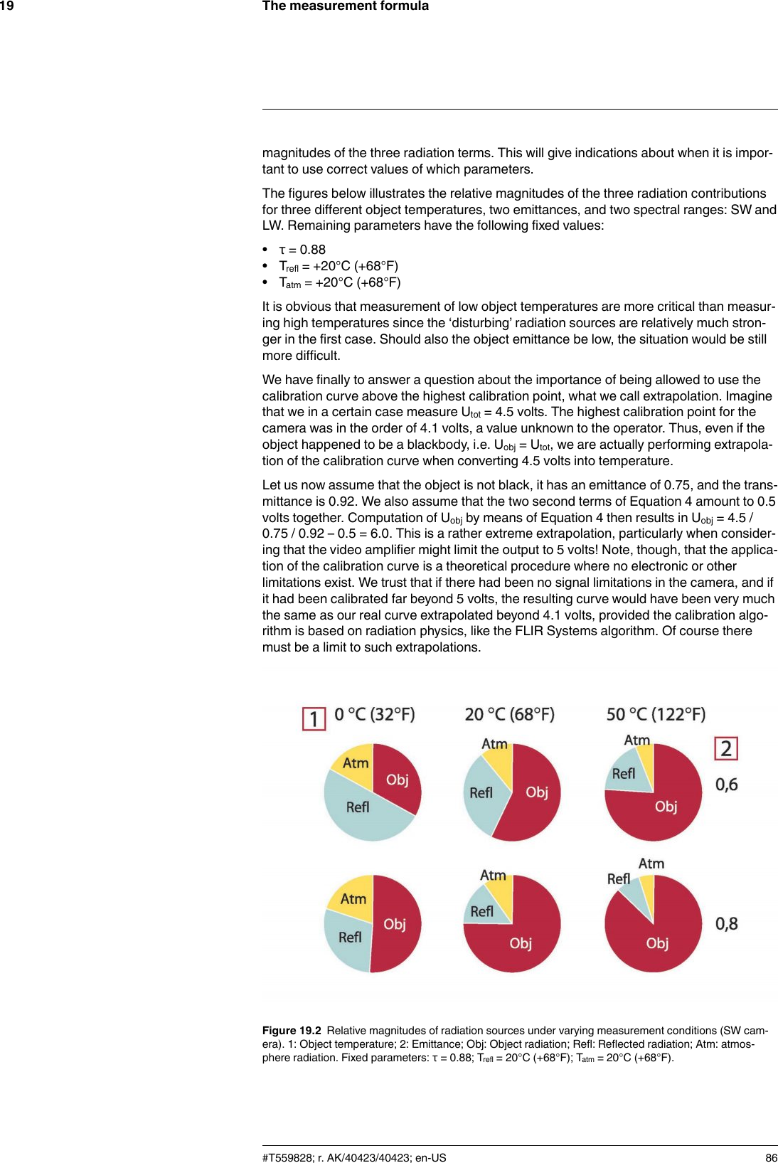
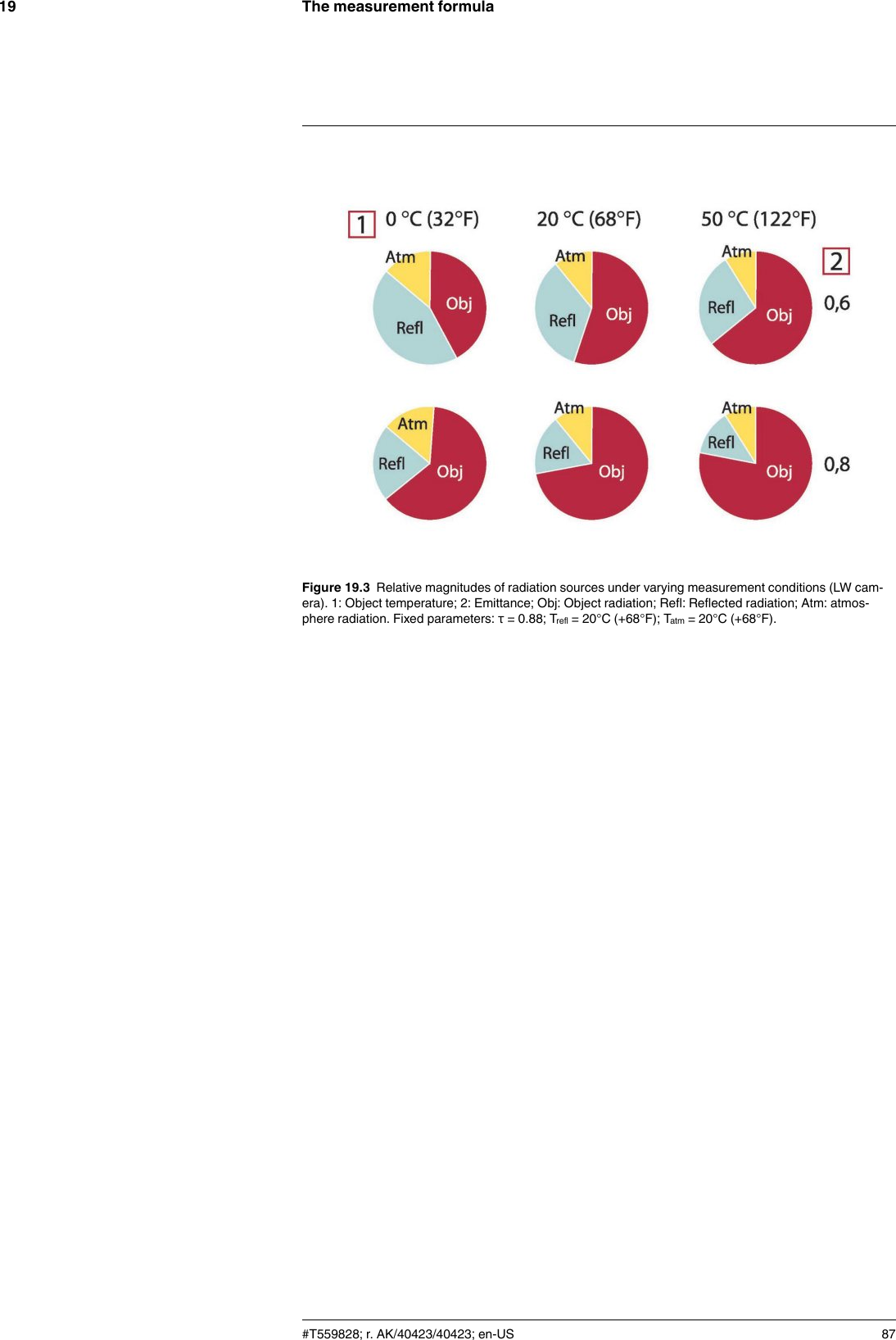
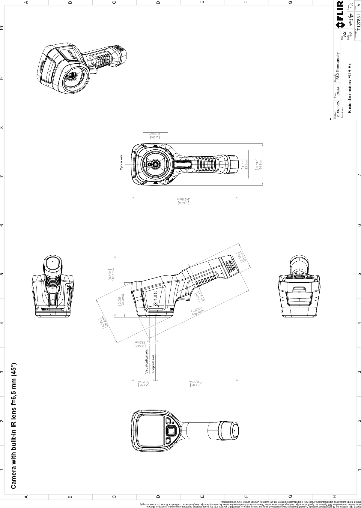
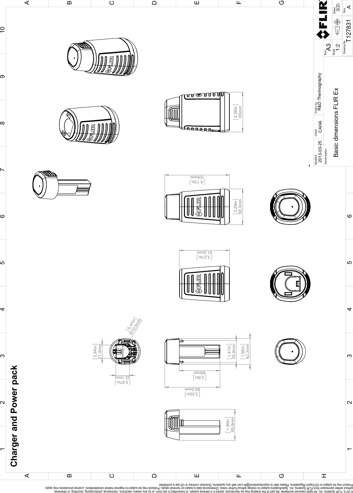
![Mechanical drawings10[See next page]#T559828; r. AK/40423/40423; en-US 54](https://usermanual.wiki/FLIR-Systems/FLIRE6390/User-Guide-3315915-Page-62.png)
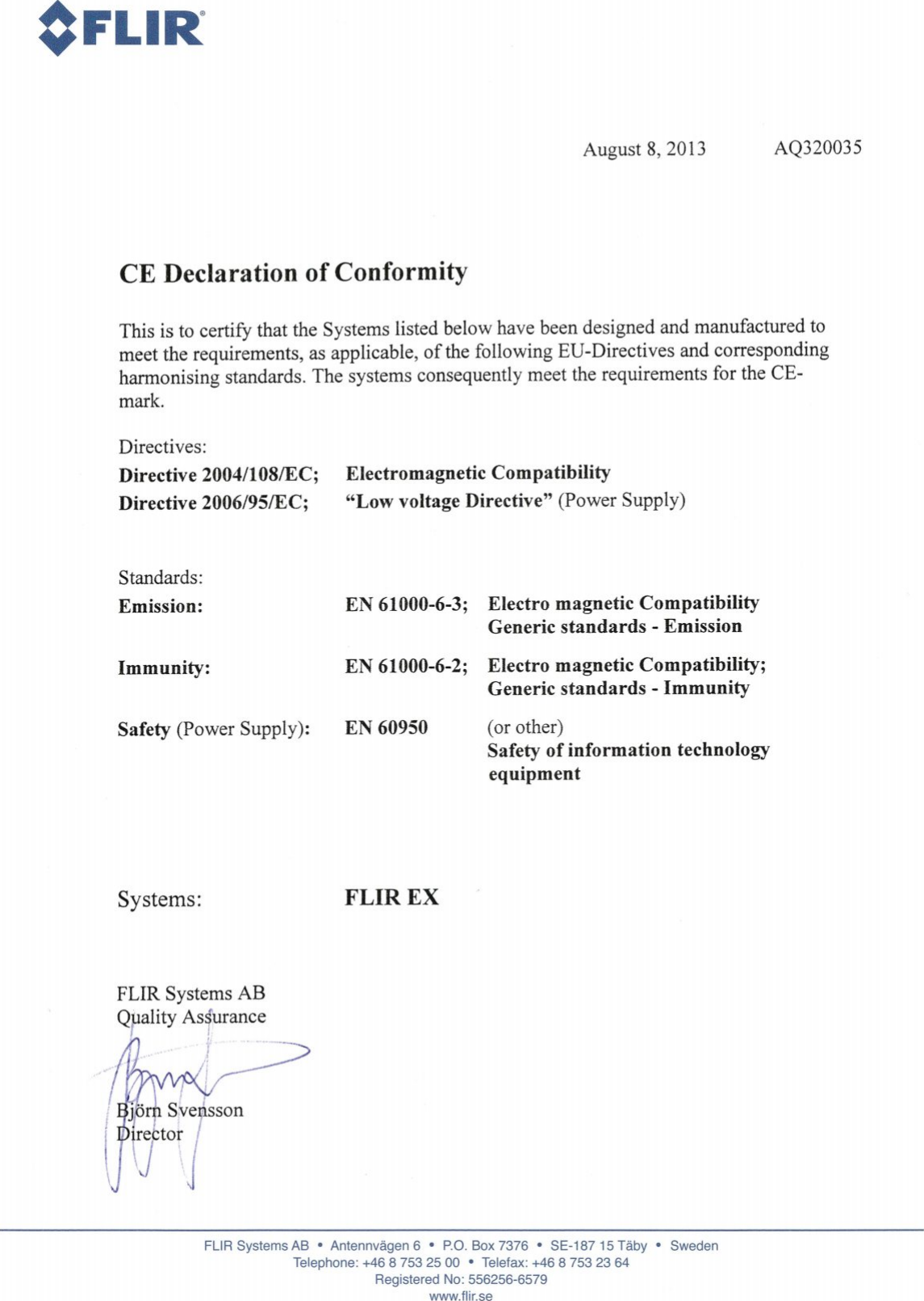
![CE Declaration of conformity11[See next page]#T559828; r. AK/40423/40423; en-US 57](https://usermanual.wiki/FLIR-Systems/FLIRE6390/User-Guide-3315915-Page-65.png)