FLIR Systems MR7X Humidity meter with Bluetooth User Manual
FLIR Systems AB Humidity meter with Bluetooth
User manual
User’s manual
FLIR MR77
Pinless moisture psychrometer with infrared
thermometer and Bluetooth METERLiNK®

User’s manual
FLIR MR77
#T559822; r.9065/9080; en-US

Table of contents
1 Disclaimers. . . . . . . . . . . . . . .. . . . . . . . . . . . . . . . . .. . . . . . . . . . . . . . . . . .. . . . . . . . . . . 1
1.1 Copyright. . . . . . . . . . . . . . . . . . . . . .. . . . . . . . . . . . . . . . . .. . . . . . . . . . . . . . . 1
1.2 Quality assurance . . . . . . . . . . . . . . . .. . . . . . . . . . . . . . . . . .. . . . . . . . . . . 1
1.3 Documentation updates . . . . . . . . . . . . . . . . .. . . . . . . . . . . . . . . . . .. . . . 1
1.4 Disposal of electronic waste. . . . . . . . . . . . . . . . . . . . . . . . . . .. . . . . . . . 1
2 Safety information . . . . . . . . . . . . . .. . . . . . . . . . . . . . . . . .. . . . . . . . . . . . . . . . . .. . . . 2
2.1 FCC Complicance . . . . . . . . . . . . . . . . . . . . . . . . . . . . . .. . . . . . . . . . . . . . . 2
2.2 Industry Canada compliance . . . . .. . . . . . . . . . . . . . . . . .. . . . . . . . . . . 3
3 Introduction . . . . . . . . . . . . . . . . . . . . .. . . . . . . . . . . . . . . . . .. . . . . . . . . . . . . . . . . . . . .. 4
3.1 Key features. . . . . . . . . . . . . . . . . . .. . . . . . . . . . . . . . . . . .. . . . . . . . . . . . . . . 4
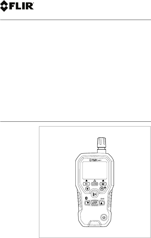
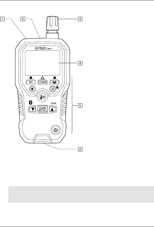
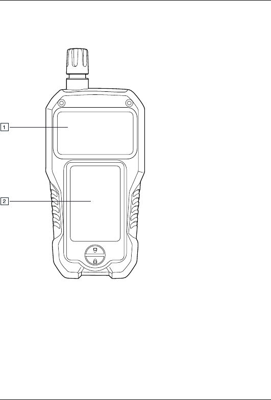
4 Description . . . . . . . . . . . . . . . . . . . . . . . . . . . . .. . . . . . . . . . . . . . . . . .. . . . . . . . . . . . . . . 5
4.1 Meter description . . . . . . . . . . . . . . . . . . . . . . . .. . . . . . . . . . . . . . . . . .. . . . 5
4.2 Function buttons . . . . . . . . . . . . . . . . . . . . .. . . . . . . . . . . . . . . . . .. . . . . . . . 7
4.3 Display description . . . . . . . . . . . . . . . . . .. . . . . . . . . . . . . . . . . .. . . . . . . . 8
4.4 Status icons and indicators. . . . . . . . . . . . . . . . . . . . . . . . . . . . . . . .. . . . 8
5 Operation . . . . . . . . . . . . . . . . .. . . . . . . . . . . . . . . . . .. . . . . . . . . . . . . . . . . .. . . . . . . . . .11
5.1 Powering the meter . . . . . . . . . . . . . . . . . . . . . . . . . . . . . . . . .. . . . . . . . . .11
5.2 Moisture measurements. . . . . . . . . . . . . . . . .. . . . . . . . . . . . . . . . . .. . .11
5.3 Hygrometric measurements . . . . . . . . . . . . .. . . . . . . . . . . . . . . . . .. . .13
5.4 IR temperature measurements. . . . . . . . . . . . . . . . .. . . . . . . . . . . . . .14
5.5 Condensation measurements . . . . . . . . . . . . . . . . . . . . . . . . .. . . . . . .15
5.6 Vapor pressure measurements . . . . . . . . . . . . . . . . . . . . . . .. . . . . . .16
5.7 Selecting measurement units . . . . . . . . . . . . . . . . . . . . . . . . . . . . . . . .17
5.8 Storing and recalling measurements. . . . . . . . . . . . . . . . . . . . . . . . .17
5.9 Alarm settings. . . . . . . . . . . . . . . . . . . . . . . .. . . . . . . . . . . . . . . . . .. . . . . . .18
5.10 Locked mode . . . . . . . . . . . . . . . . . . . . . . . . . . . . . . .. . . . . . . . . . . . . . . . . .19
5.11 Streaming measurement data using Bluetooth . . . . . . . . . . . . . . 19
6 Maintenance. . . . . . . . . . . . . . . . . . . . .. . . . . . . . . . . . . . . . . .. . . . . . . . . . . . . . . . . .. . .21
6.1 Cleaning and storage. . . . . . . . .. . . . . . . . . . . . . . . . . .. . . . . . . . . . . . . .21
6.2 Battery replacement . . . . . . . . . . . . . . . . . . . . . . . . . . . . . . . .. . . . . . . . . .21
7 Material groups . . . . . . . . . . . . . . . . . . . . . . . . . . . .. . . . . . . . . . . . . . . . . .. . . . . . . . . .22
8 Technical specifications . . . . . . . . . . . . . . . . . . . . . . . . .. . . . . . . . . . . . . . . . . .. . .23
8.1 General specifications . . . . .. . . . . . . . . . . . . . . . .. . . . . . . . . . . . . . . . . .23
8.2 Humidity meter specifications . . . . . . . . . . . . . . . . . . . . . . . . .. . . . . . .24
#T559822; r.9065/9080; en-US v

Table of contents
8.3 Moisture specifications . . . . . . . . . . . . . . . . . . . . . . . . .. . . . . . . . . . . . . .24
8.4 Thermal measurement range specifications. . . . . . . . . . . . . .. . .25
8.5 Vapor pressure specifications . . . . . . . . . . . . . .. . . . . . . . . . . . . . . . . .25
9 Technical support . . . . . . . . . . . . . . . . . . . . . . . . .. . . . . . . . . . . . . . . . . .. . . . . . . . . .26
10 Warranties . . . . . . . . . . . . . . . . . . . . . . .. . . . . . . . . . . . . . . . . .. . . . . . . . . . . . . . . . . .. . .27
10.1 FLIR Global Limited Lifetime Warranty . . . . . . . .. . . . . . . . . . . . . .27
10.2 FLIR Test and Measurement Limited 2 Year
Warranty . . . . . . . . . . . . . . . . . .. . . . . . . . . . . . . . . . . . . . .. . . . . . . . . . . . . . . 28
#T559822; r.9065/9080; en-US vi
1 Disclaimers
1.1 Copyright
© 2013, FLIR Systems, Inc. All rights reserved worldwide.
No parts of the software including source code may be re-
produced, transmitted, transcribed or translated into any
language or computer language in any form or by any
means, electronic, magnetic, optical, manual or otherwise,
without the prior written permission of FLIR Systems.
The documentation must not, in whole or part, be copied,
photocopied, reproduced, translated or transmitted to any
electronic medium or machine readable form without prior
consent, in writing, from FLIR Systems.
Names and marks appearing on the products herein are
either registered trademarks or trademarks of FLIR Sys-
tems and/or its subsidiaries. All other trademarks, trade
names or company names referenced herein are used for
identification only and are the property of their respective
owners.
1.2 Quality assurance
The Quality Management System under which these
products are developed and manufactured has been certi-
fied in accordance with the ISO 9001 standard.
FLIR Systems is committed to a policy of continuous de-
velopment; therefore we reserve the right to make
changes and improvements on any of the products with-
out prior notice.
1.3 Documentation updates
Our manuals are updated several times per year, and we
also issue product-critical notifications of changes on a
regular basis.
To access the latest manuals and notifications, go to the
Download tab at:
http://support.flir.com
It only takes a few minutes to register online. In the down-
load area you will also find the latest releases of manuals
for our other products, as well as manuals for our historical
and obsolete products.
1.4 Disposal of electronic waste
As with most electronic products, this equipment must be
disposed of in an environmentally friendly way, and in ac-
cordance with existing regulations for electronic waste.
Please contact your FLIR Systems representative for
more details.
#T559822; r.9065/9080; en-US 1
2 Safety information
Note
Before operating the device, you must read, understand, and follow all in-
structions, dangers, warnings, cautions, and notes.
Note
FLIR Systems reserves the right to discontinue models, parts or accessories,
and other items, or to change specifications at any time without prior notice.
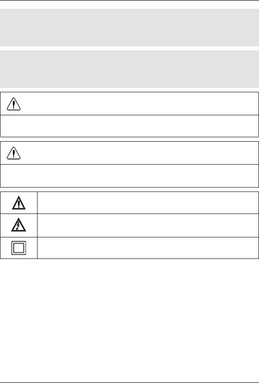
WARNING
Do not look directly into the laser beam. The laser beam can cause eye
irritation.
WARNING
Do not use the laser pointer near explosive gases or in other possible explo-
sive areas. Injury to persons can occur.
This symbol, adjacent to another symbol or terminal, indicates that
the user must refer to the manual for further information.
This symbol, adjacent to a terminal, indicates that, under normal
use, hazardous voltages may be present.
Double insulation.
2.1 FCC Complicance
This device complies with part 15 of the FCC Rules. Operation is subject to the
following two conditions:
1. This device may not cause harmful interference.
2. This device must accept any interference received, including interference
that may cause undesired operation.
This equipment has been tested and found to comply with the limits for a Class B
digital device, pursuant to part 15 of the FCC Rules. These limits are designed to
#T559822; r.9065/9080; en-US 2
2 Safety information
provide reasonable protection against harmful interference in a residential instal-
lation. This equipment generates, uses, and can radiate radio frequency energy
and, if not installed and used in accordance with the instructions, may cause
harmful interference to radio communications. However, there is no guarantee
that interference will not occur in a particular installation. If this equipment does
cause harmful interference to radio or television reception, which can be deter-
mined by turning the equipment off and on, the user is encouraged to try to cor-
rect the interference by one or more of the following measures:
• Reorient or relocate the receiving antenna.
• Increase the separation between the equipment and receiver.
• Connect the equipment into an outlet on a circuit different from that to which
the receiver is connected.
• Consult the dealer or an experienced radio/TV technician for help.
WARNING
Changes or modifications not expressly approved by the party responsible for
compliance could void the user's authority to operate the equipment.
2.2 Industry Canada compliance
This device complies with Industry Canada licence-exempt RSS standard(s). Op-
eration is subjectto the following two conditions: (1) this device may not cause in-
terference, and (2) this devicemust accept any interference, including
interference that may cause undesired operation of thedevice.
#T559822; r.9065/9080; en-US 3

3 Introduction
Congratulations on your purchase of the FLIR MR77 with METERLiNK® Blue-
tooth capabilities for use with FLIR infrared (IR) cameras.
This pinless moisture meter incorporates a patented built-in IR thermometer and
20-point memory. You can monitor moisture in wood and other building materials
with no surface damage with the pinless moisture sensor (pin-type moisture
probe included), and measure humidity and air temperature with the built-in
probe, plus non-contact IR temperature using its patented IR design. Advanced
functions provide moisture content, dew point, and vapor pressure calculations.
This meter is shipped fully tested and calibrated and, with proper use, will provide
years of reliable service.
3.1 Key features
• Quickly indicates the moisture content of materials with pinless technology
without damaging the surface.
• Optional remote pin-type probe (MR77-P) allows for moisture readings at dif-
ferent penetration levels (0.9 m (3′) cable length).
• Easy to read, large dual display with backlight feature.
• Simultaneously displays the percentage moisture content of wood or material
being tested and the air temperature, IR temperature, or humidity.
• Uses a patented IR design to measure non-contact surface temperature, with
an 8:1 distance-to-spot ratio and 0.95 fixed emissivity.
• Built-in humidity/temperature probe measures relative humidity and air tem-
perature plus the mixing ratio and the dew point.
• Measures ambient and surface vapor pressure.
• Automatically calculates the differential temperature.
• Minimum/maximum and data hold modes.
• 20-point internal memory.
• Auto power off and low battery indication.
#T559822; r.9065/9080; en-US 4
4 Description
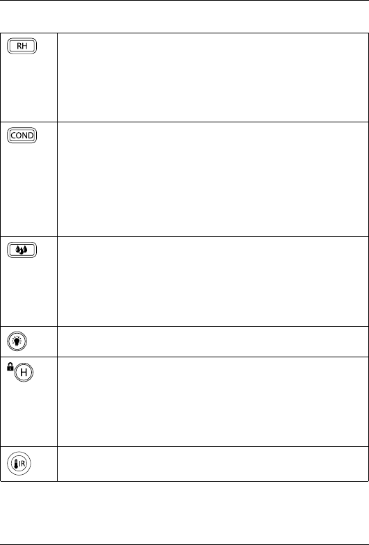
4.2 Function buttons
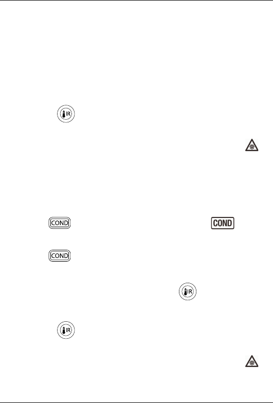
• Press the button to enter Hygrometer mode, see section 5.3
Hygrometric measurements, page 13.
• Press the button repeatedly to cycle through the display of rel-
ative humidity, dew point temperature, and mix ratio.
• Press and hold the button for 2 seconds to enter Humidity
alarm set mode, see section 5.9 Alarm settings, page 18.
• Press the button to enter Condensation mode, see section
5.5 Condensation measurements, page 15.
• Press the button repeatedly to toggle between Condensation
mode and Vapor pressure mode, see section 5.6 Vapor pres-
sure measurements, page 16.
• When in Moisture mode, press and hold the button for 2 sec-
onds to toggle between the relative and absolute readings,
see section 5.2 Moisture measurements, page 11.
• Press the button to enter Moisture mode, see section 5.2
Moisture measurements, page 11.
• Press the button repeatedly to toggle between the internal
sensor and external pin probe measurements.
• Press and hold the button for 2 seconds to enter Moisture
alarm set mode, see section 5.9 Alarm settings, page 18.
Press the button to enable/disable the display backlight.
• Press the button to toggle between Normal and Hold mode. In
Hold mode, the display freezes the last reading and continues
to display this value.
• Press and hold the button for 5 seconds to toggle between
Normal and Locked mode, see section 5.10 Locked mode,
page 19.
Press and hold the button to enable IR temperature measure-
ments, see section 5.4 IR temperature measurements, page 14.
#T559822; r.9065/9080; en-US 7
4 Description
• Press and hold the button for 2 seconds to change the unit
setting. For more information, see section 5.7 Selecting meas-
urement units, page 17.
• When in View data mode, press the button to step through the
datalogger memory locations.
When in View data mode, press the button to step through the
datalogger memory locations.
Press the button to capture and store the current readings. For
more information, see section 5.8 Storing and recalling measure-
ments, page 17.
Press the button to switch the meter on/off.
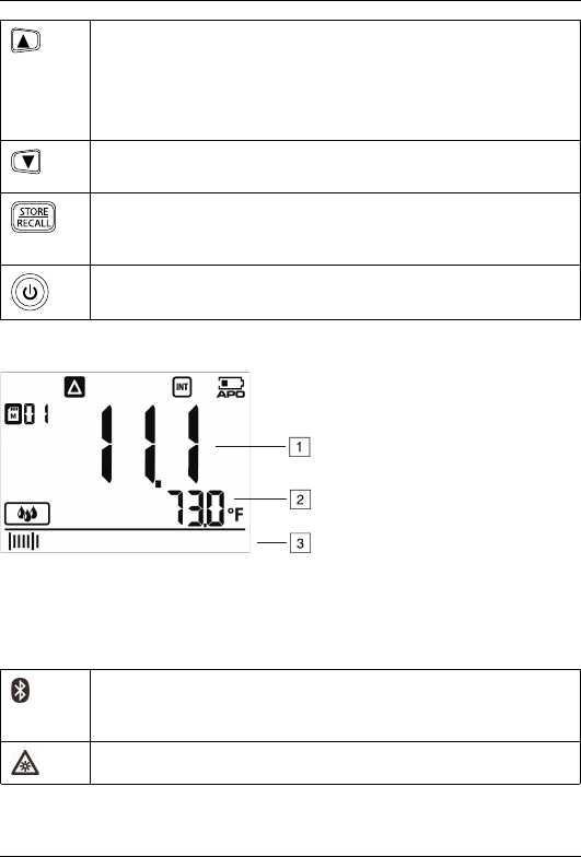
4.3 Display description
1. Main display.
2. Secondary display.
3. Bar graph (matches the reading on the main display).
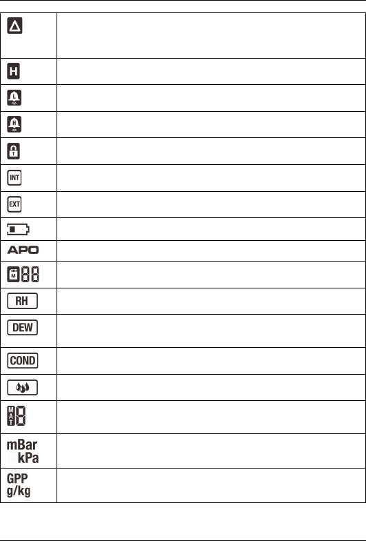
4.4 Status icons and indicators
Indicates that METERLiNK® (Bluetooth) communication is ac-
tive, see section 5.11 Streaming measurement data using Blue-
tooth, page 19.
Indicates that the IR sensor and the laser pointer diode are active.
#T559822; r.9065/9080; en-US 8
4 Description
Indicates that the meter is displaying relative moisture measure-
ments (solid indicator) or absolute moisture measurements
(flashing indicator).
Indicates that the meter is in Hold mode.
Indicates that the reading is lower than the Low alarm threshold.
Indicates that the reading is higher than the High alarm threshold.
Indicates that the meter is in Locked mode.
Indicates that the internal moisture sensor is active.
Indicates that the external pin probe is active.
Indicates the battery voltage status.
Indicates that the auto power off function is enabled.
Indicates the active datalogger memory location (1–20).
Indicates that the meter is in Hygrometer mode.
Indicates that the meter is displaying dew point temperature read-
ings on the main display.
Indicates that the meter is in Condensation mode.
Indicates that the meter is in Moisture mode.
Indicates the number that represents the material group under
test, see section 7 Material groups, page 22.
Indicates that the meter is displaying vapor pressure in millibar
(mBar) or in kilopascal (kPa) units.
Indicates that the meter is displaying the mixing ratio in grains per
pound (GPP) or in grams per kilogram (g/kg) units.
#T559822; r.9065/9080; en-US 9

4 Description
Indicates that the meter is displaying relative humidity in percent
(%) units.
Indicates that the meter is displaying temperature in degrees Cel-
sius (℃) units.
Indicates that the meter is displaying temperature in degrees Fah-
renheit (℉) units.
High/low calibration point.
#T559822; r.9065/9080; en-US 10

5 Operation
5.1 Powering the meter
1. Remove the protective cap from the humidity sensor/thermometer assembly.
2. Press the button to switch on the meter.
3. If the battery indicator shows that the battery voltage is low or if the me-
ter does not power on, replace the battery. See section 6.2 Battery replace-
ment, page 21.
4. Press the button to switch off the meter.
5.1.1 Auto power off
The meter enters sleep mode after 30 minutes of inactivity. The meter beeps
three times 20 seconds before powering off. Press any function button to prevent
the meter from powering off. The auto power off time-out is then reset.
5.1.1.1 Disable auto power off
1. To disable the auto power off function, start with the meter switched off.
2. Simultaneously press and hold the and buttons until the in-
dicator disappears, indicating that the function is disabled.
5.2 Moisture measurements
With the meter in Moisture mode, moisture measurements can be performed us-
ing either the internal moisture sensor or by connecting the external pin probe.
The internal moisture sensor can detect moisture to a depth of 19 mm (0.75″).
The internal moisture reading can be relative or absolute.
The three-digit main display shows the moisture reading, and the four-digit sec-
ondary display shows the ambient air temperature. The bar graph matches the
reading on the main display.
While in Moisture mode, IR measurements may also be performed, see section
5.4 IR temperature measurements, page 14.
#T559822; r.9065/9080; en-US 11

5 Operation
5.2.1 Internal moisture sensor
1. Press the button to enter the Moisture mode.
The and indicators are displayed. The indicator is also dis-
played, indicating that the meter is displaying relative measurements. The
ambient temperature is displayed on the secondary display.
2. Place the internal moisture sensor (located on the rear side of the meter) on
the surface of the material to be tested.
The relative moisture reading is displayed on the main display. No units of
measurement are displayed.
3. For absolute measurements, follow the steps below:
1. For best results, keep hands and other surfaces and objects away from
the internal moisture sensor area.
2. Press and hold the button for 2 seconds until the indicator
flashes, to zero the moisture reading and enable absolute
measurements.
3. Place the internal moisture sensor on the surface of the material to be
tested.
The absolute moisture reading is displayed on the main display. No units
of measurement are displayed.
4. Press and hold the button for 2 seconds to return to relative
measurements.
5.2.2 External pin probe
1. Connect the external pin probe to the EXT connection jack (located at the
bottom of the meter).
2. Press the button to enter the Moisture mode. The indicator is
displayed.
3. Press the button once more to activate external pin probe measure-
ments. The indicator is displayed.
#T559822; r.9065/9080; en-US 12
5 Operation
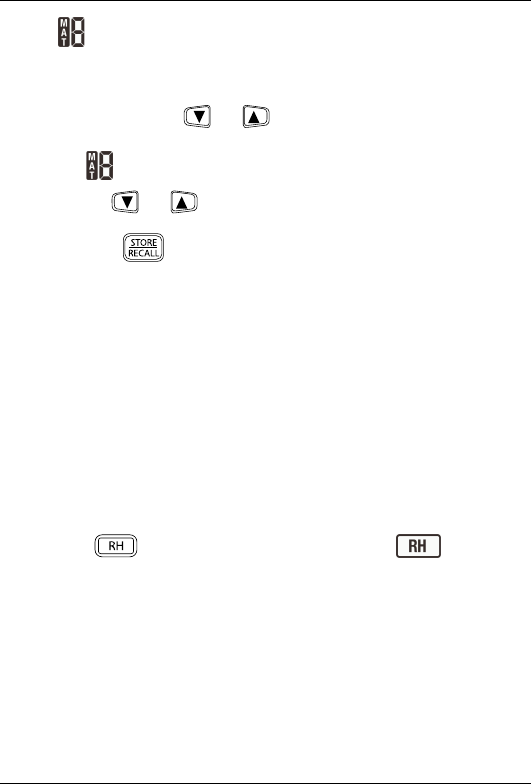
4. The indicator shows the currently selected material group number. Refer
to section 7 Material groups, page 22.
To change the material group number, do the following:
1. Press and hold the and buttons for 2 seconds to enter the Ma-
terial group selection mode.
The indicator flashes.
2. Use the and buttons to step through the nine material group
numbers.
3. Press the button to set the group and exit the Material group se-
lection mode.
5. Press the probe pins into the material.
The moisture reading is displayed on the main display, in percent (%).
5.3 Hygrometric measurements
In Hygrometer mode, the meter measures and displays the relative humidity, dew
point temperature, mixing ratio, and ambient air temperature.
The three-digit main display shows the relative humidity, dew point temperature,
or mixing ratio, and the four-digit secondary display shows the ambient air tem-
perature. The bar graph matches the reading on the main display.
While in Hygrometer mode, IR measurements may also be performed, see sec-
tion 5.4 IR temperature measurements, page 14.
1. Press the button to enter Hygrometer mode. The indicator is
displayed.
2. The relative humidity is displayed on the main display. The ambient air tem-
perature is displayed on the secondary display.
#T559822; r.9065/9080; en-US 13
5 Operation
3. Press the button repeatedly to cycle through the display of relative hu-
midity, dew point temperature, and mixing ratio.
• Relative humidity: The indicator is displayed and the reading is
displayed in percent (%).
• Dew point temperature: The indicator is displayed and the reading
is displayed in ℃or ℉, depending on the unit setting.
• Mixing ratio: The reading is displayed in grains per pound (GPP) or grams
per kilogram (g/kg), depending on the unit setting.
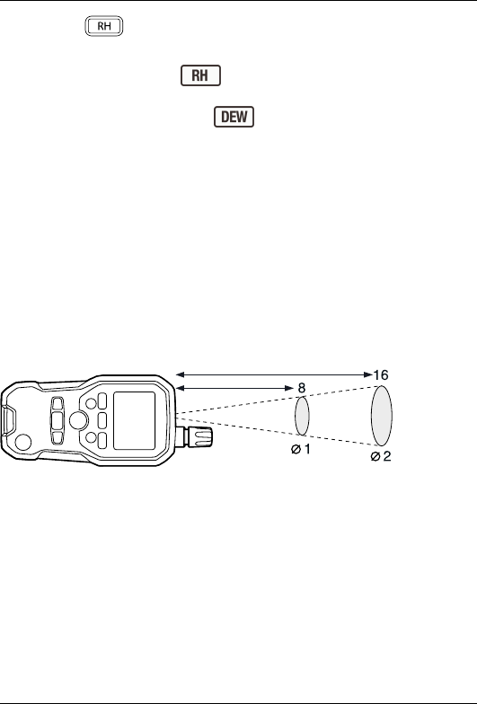
5.4 IR temperature measurements
IR temperature measurements can be performed in all operating modes.
The meter is equipped with a laser pointer diode, which is used as a targeting
pointer for the IR temperature measurements. The target of the measurement
should be larger than the size of the laser beam spot. As the distance from an ob-
ject increases, the spot size of the area measured by the meter becomes larger.
The meter’s field of view ratio is 8:1, meaning that if the meter is 8 cm (3.2″) from
the target, the diameter (spot) of the object under test must be at least 1 cm
(0.4″). Refer to Figure 5.1.
Figure 5.1 IR spot-to-distance ratio
IR measurement notes:
• The object under test should be larger than the than the size of the laser
beam spot.
• If the surface of the object under test is covered with frost, oil, grime, etc.,
clean the surface before measuring.
• If the surface of the object is highly reflective, apply masking tape or flat black
paint to the surface before measuring.
• The meter may not make accurate measurements through transparent surfa-
ces such as glass.
#T559822; r.9065/9080; en-US 14
5 Operation
• Steam, dust, smoke, etc., may obscure measurements.
• To find a hot spot, aim the meter outside the area of interest, then scan across
(in an up and down motion) until the hot spot is located.
WARNING
Do not look directly into the laser beam. The laser beam can cause eye
irritation.
WARNING
Do not use the laser pointer near explosive gases or in other possible explo-
sive areas. Injury to persons can occur.
1. Press and hold the button to enable the IR sensor and the laser pointer
diode. The indicator is displayed.
2. Aim the laser pointer at the surface to be measured. The IR temperature
reading is displayed on the four-digit secondary display.
3. Release the button to disable the IR sensor and the laser pointer diode.
The last IR temperature reading remains on the display for 8 seconds; then
the meter returns to a display of the ambient air temperature, and the in-
dicator disappears.
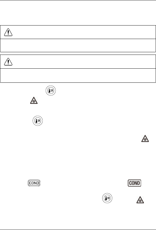
5.5 Condensation measurements
In Condensation mode, the meter determines whether a surface is at risk of con-
densation, based on measurements of the dew point temperature (relative hu-
midity and ambient air temperature) and the IR temperature of the surface.
1. Press the button to enter the Condensation mode. The indica-
tor is displayed.
2. Aim the meter at the surface. Press and hold the button. The indi-
cator is displayed
#T559822; r.9065/9080; en-US 15
5 Operation
3. The dew point temperature is displayed on the main display. The IR tempera-
ture of the surface is displayed on the secondary display. The bar graph indi-
cates the level of risk for condensation:
• If the IR temperature is more than 14℃(25℉) above the dew point tem-
perature, the bar graph is empty.
• If the IR temperature is 3–14℃(5–25℉) above the dew point tempera-
ture, the bar graph indicates a percentage of full scale.
• If the IR temperature is less than 3℃(5℉) above the dew point tempera-
ture, the bar graph is full.
4. Release the button to disable the IR sensor and the laser pointer diode.
The last IR temperature reading remains on the display for 8 seconds; then
the meter returns to a display of the ambient air temperature and the in-
dicator disappears.
5.6 Vapor pressure measurements
Vapor pressure measurement is a special variant of condensation measurement.
The meter calculates the vapor pressure based on measurements of the relative
humidity and the IR temperature of the surface.
1. Press the button to enter Condensation mode. The indicator is
displayed. The unit of measurement on the main display is ℃or ℉, depend-
ing on the unit setting.
2. Press the button once more to enter Vapor pressure mode. The unit
of measure on the main display changes to kPa or mBar, depending on unit
setting.
3. Aim the meter at the surface. Press and hold the button.
4. The vapor pressure is displayed on the main display. The IR temperature of
the surface is displayed on the secondary display.
5. Release the button to disable the IR sensor and the laser pointer diode.
The last IR temperature reading remains on the display for 8 seconds; then
the meter returns to a display of the ambient air temperature and the in-
dicator disappears.
#T559822; r.9065/9080; en-US 16

5 Operation
5.7 Selecting measurement units
There are two sets of units; US and metric. The unit setting can be changed at
any time in any mode, by pressing and holding the button for 2 seconds.
The unit setting applies to all modes. It is not possible to, for example, display
moisture in g/kg while showing temperature in ℉.
US unit setting:
• Temperature is displayed in degrees Fahrenheit (℉).
• Mixing ratio is displayed in grains per pound (GPP).
• Vapor pressure is displayed in millibars (mBar).
Metric unit setting:
• Temperature is displayed in degrees Celsius (℃).
• Mixing ratio is displayed in grams per kilogram (g/kg).
• Vapor pressure is displayed in kilopascals (kPa).
5.8 Storing and recalling measurements
5.8.1 Datalogger memory locations
The meter has 20 datalogger memory locations for the storage of measurement
data. Each memory location stores the current readings for all operating modes,
with the current unit settings. Thus, each location contains moisture, humidity,
ambient temperature, and IR temperature data.
5.8.2 Storing a measurement
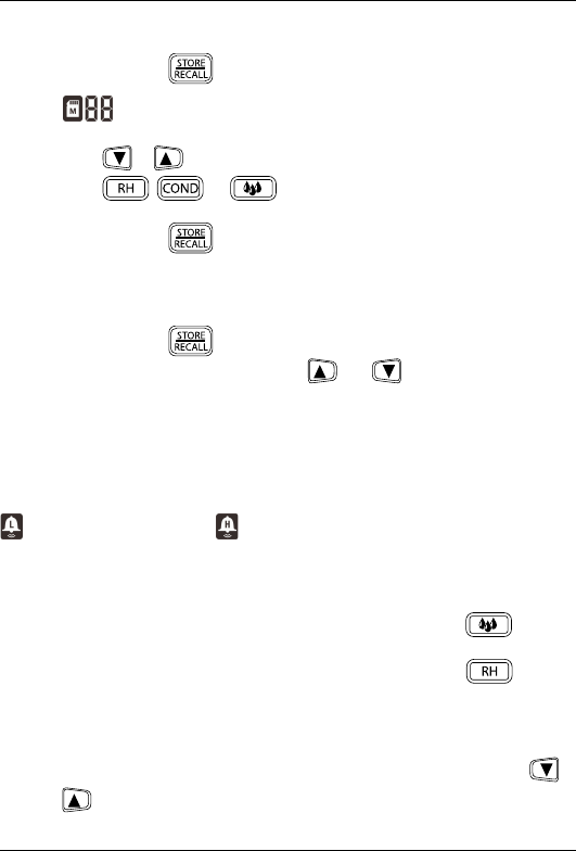
1. Press the button to capture and store the currently displayed readings.
The data is saved to the memory location shown by the indicator.
The memory location indicator then advances to the next location. When the
20 memory locations are full, the meter overwrites saved readings, starting
with memory location 1.
#T559822; r.9065/9080; en-US 17
5 Operation
5.8.3 View data
1. Press and hold the button for 2 seconds to enter View data mode.
The indicator flashes, and the data stored in that location is
displayed.
2. Press the or button to step through the memory locations.
3. Press the , , or button to display the stored data for the
different modes.
4. Press and hold the button for 2 seconds until a single beep sounds to
exit View data mode.
5.8.4 Clearing the memory from data
1. Press and hold the button for 2 seconds to enter View data mode.
2. In View data mode, press and hold the and buttons simultaneously
for 3 seconds to clear all data.
5.9 Alarm settings
High and low alarm thresholds can be set for moisture and humidity measure-
ments. If either of the thresholds is exceeded during the measurement, the meter
beeps and the corresponding alarm indicator is displayed: the low alarm indicator
or the high alarm indicator .
The default setting for the moisture and humidity alarms is off.
1. To enter the alarm set mode, do one of the following:
• To enter the Moisture alarm set mode, press and hold the button
for 2 seconds.
• To enter the Humidity alarm set mode, press and hold the button
for 2 seconds.
The current high threshold or OFF (if the alarm is disabled) is flashing on the
main display.
2. To switch from OFF to the numerical display, simultaneously press the
and buttons.
#T559822; r.9065/9080; en-US 18
5 Operation
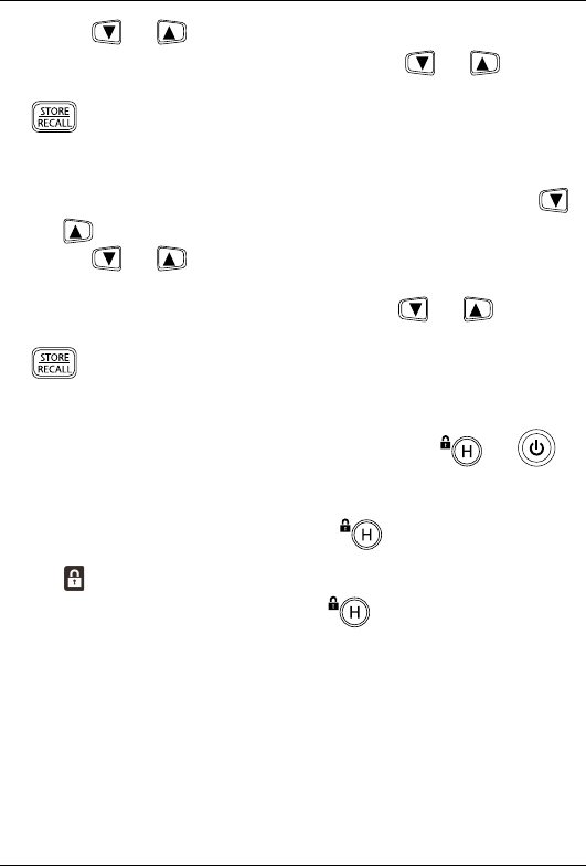
3. Use the and buttons to adjust the high alarm threshold.
4. To disable the high alarm, simultaneously press the and buttons.
5. When the desired high alarm threshold (or OFF) is displayed, press the
button to save the value.
The current low threshold or OFF (if the alarm is disabled) is now flashing on
the main display.
6. To switch from OFF to the numerical display, simultaneously press the
and buttons.
7. Use the and buttons to adjust the low alarm threshold. The low
alarm value cannot exceed the high alarm value.
8. To disable the low alarm, simultaneously press the and buttons.
9. When the desired low alarm threshold (or OFF) is displayed, press the
button to save the value and exit the alarm set mode.
5.10 Locked mode
In Locked mode, the meter ignores all button presses except and .
The auto power off function, see section 5.1.1 Auto power off, page 11, is dis-
abled in Locked mode.
1. To enter Locked mode, press and hold the button for 5 seconds.
The indicator is displayed.
2. To exit Locked mode, press and hold the button for 5 seconds once
again.
5.11 Streaming measurement data using Bluetooth
5.11.1 General
Some IR cameras from Flir Systems support Bluetooth communication and to
those cameras you can stream measurement data from the meter. The data is
then merged into the result table in the IR image.
#T559822; r.9065/9080; en-US 19

5 Operation
Streaming measurement data is a convenient way to add important information
to an IR image. For example, when identifying a water leakage in a wall, you may
want to know the humidity in the wall.
The Bluetooth range is 10m (32ft) maximum.
5.11.2 Procedure
1. Pair the IR camera with the instrument. Refer to the camera manual for infor-
mation on how to pair Bluetooth devices.
2. Turn on the camera.
3. Turn on the meter.
4. Press and hold the button on the meter to enable Bluetooth.
5. Take a measurement reading. Results from the meter will now automatically
be displayed in the result table in the top left corner of the IR camera screen.
#T559822; r.9065/9080; en-US 20
6 Maintenance
6.1 Cleaning and storage
Clean the meter with a damp cloth and mild detergent; do not use abrasives or
solvents.
If the meter is not to be used for an extended period, remove the battery and
store it separately.
6.2 Battery replacement
1. Switch off the meter before attempting to replace the battery.
2. Unscrew and remove the battery compartment cover.
3. Replace the standard 9 V battery.
4. Secure the battery compartment cover.
6.2.1 Disposal of electronic waste
As with most electronic products, this equipment must be disposed of in an envi-
ronmentally friendly way, and in accordance with existing regulations for elec-
tronic waste.
Please contact your FLIR Systems representative for more details.
#T559822; r.9065/9080; en-US 21

8 Technical specifications
Accuracy specifications for all measurement ranges are applicable under the fol-
lowing ambient conditions: 18 ℃to 28 ℃(64.4 ℉to 82.4 ℉); <80% RH.
8.1 General specifications
Display • 3-digit 15 mm (0.6″) main display
• 4-digit 6 mm (0.24″) secondary
display
• 10-segment bar graph
• Memory counter
Controls • 7 dedicated function buttons:
moisture, relative humidity, con-
densation, hold/lock, up (⇑), down
(⇓), store/recall
• 4 auxiliary buttons: IR, Bluetooth,
backlight/work light, power
Other indications • 24 icon-style locations + 2-digit
memory indicator
• Piezo beeper (85 dBA)
Sample rate 2 per second
Backlight White LED
Internal memory (1) storage location
Power supply 1 × 9 V battery (MN1604 or
equivalent)
Battery life 100 hours, using alkaline batteries,
with no backlight/work light use
Auto power off (APO) After 30 minutes (nominal) inactivity,
with audible pre-alert; reset when the
power button is pressed. Disable
function supported
APO quiescent current 50 µA maximum
#T559822; r.9065/9080; en-US 23

8 Technical specifications
Operating temperature 0 to 50℃(32 to 122℉)
Storage temperature –10 to 60℃(14 to 140℉)
Operating humidity • 90%, 0 to 30℃(32 to 86℉)
• 75%, 30 to 40℃(86 to 104℉)
• 45%, 40 to 50℃(104 to 122℉)
Storage humidity 90% maximum
Dimensions (excluding sensor) 139 mm × 72 mm × 42 mm (5.4″ ×
2.8″ × 1.7″)
Weight 0.29 kg (0.65 lb.), including batteries
Bluetooth range 10m (32ft) maximum
Agency approvals FCC Class B
8.2 Humidity meter specifications
Function Range Accuracy (of reading)
Relative humidity
measurement
20 to 30℃(68 to 86℉)
0–10% ±3%
10–90% ±2.5%
90–99% ±3%
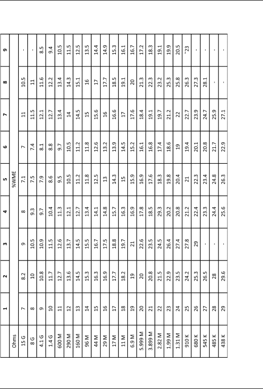
8.3 Moisture specifications
Function Range Accuracy (of reading)
Pin moisture 0–99% WME ±5%
Pin-less moisture range 0–99.9 Relative measurement
#T559822; r.9065/9080; en-US 24

8 Technical specifications
8.4 Thermal measurement range specifications
Function IR range Accuracy (of reading)
IR temperature (8:1
ratio)
–20 to –1℃(–4 to 31℉) ±5℃(±9℉)
0℃(32℉) ±1℃(±2℉)
1 to 200℃(33 to
392℉)
Greater of ±3.5% or
±5℃(±9℉)
IR Emissivity 0.95 (fixed)
Sensor temperature -28 to 77 ℃(-18 to 170
℉)
±2 ℃(3.6 ℉)
8.5 Vapor pressure specifications
Function Range Accuracy (of reading)
Vapor pressure
measurement
–1 to 60℃(30 to 140℉)
0.0–20.0 kPa Greater of ±2.0% or 0.2
kPa
Dew Point Temperature
range
-30 to 100 ℃(-22 to
199 ℉)
Mixing Ratio range 0-999 GPP (0 to 160 g/
kg)
#T559822; r.9065/9080; en-US 25


10 Warranties
10.1 FLIR Global Limited Lifetime
Warranty
A qualifying FLIR Test and Measurement product (the
“Product”) purchased either directly from FLIR Commer-
cial Systems Inc and affiliates (FLIR) or from an author-
ized FLIR distributor or reseller that Purchaser registers
on-line with FLIR is eligible for coverage under FLIR’s Lim-
ited Lifetime Warranty, subject to the terms and conditions
in this document. This warranty only applies to purchases
of Qualifying Products (see below) purchased and manu-
factured after April 1, 2013.
PLEASE READ THIS DOCUMENT CAREFULLY; IT CON-
TAINS IMPORTANT INFORMATION ABOUT THE PROD-
UCTS THAT QUALIFY FOR COVERAGE UNDER THE
LIMITED LIFETIME WARRANTY, PURCHASER’S OBLI-
GATIONS, HOW TO ACTIVATE THE WARRANTY, WAR-
RANTY COVERAGE, AND OTHER IMPORTANT TERMS,
CONDITIONS, EXCLUSIONS AND DISCLAIMERS.
1. PRODUCT REGISTRATION. To qualify for FLIR’s Lim-
ited Lifetime Warranty, Purchaser must fully register the
Product directly with FLIR on-line at http://www.flir.com
within Sixty (60) DAYS of the date the Product was pur-
chased by the first retail customer (the “Purchase Date”).
Qualifying PRODUCTS THAT ARE NOT REGISTERED
ON-LINE WITHIN SIXTY (60) DAYS OF THE PURCHASE
DATE WILL HAVE A LIMITED ONE YEAR WARRANTY
FROM DATE OF PURCHASE.
2. QUALIFYING PRODUCTS. Upon registration, Test and
Measurement products that qualify for coverage under
FLIR’s Limited Lifetime Warranty are: MR7x, CM7x,
CM8x, DMxx, VP5x not including accessories which may
have their own warranty.
3. WARRANTY PERIODS. For purposes of the The Lim-
ited Lifetime Warranty, Lifetime is defined as seven years
(7) after the product is no longer manufactured, or ten
years (10) from date of purchase, whichever is greater.
This Warranty is only applicable to the original owner of
the Products.
Any Product that is repaired or replaced under warranty is
covered under this Limited Lifetime Warranty for one hun-
dred eighty days (180) days from the date of return ship-
ment by FLIR or for the remaining duration of the
applicable Warranty Period, whichever is longer.
4. LIMITED WARRANTY. In accordance with the terms
and conditions of this Limited Lifetime Warranty, and ex-
cept as excluded or disclaimed in this document, FLIR
warrants, from the Purchase Date, that all fully registered
Products will conform to FLIR’s published Product specifi-
cations and be free from defects in materials and work-
manship during the applicable Warranty Period.
PURCHASER’S SOLE AND EXCLUSIVE REMEDY
UNDER THIS WARRANTY, AT FLIR’S SOLE DISCRE-
TION, IS THE REPAIR OR REPLACEMENT OF
DEFECTIVE PRODUCTS IN A MANNER, AND BY A
SERVICE CENTER, AUTHORIZED BY FLIR. IF THIS
REMEDY IS ADJUDICATED TO BE INSUFFICIENT, FLIR
SHALL REFUND PURCHASER’S PAID PURCHASE
PRICE AND HAVE NO OTHER OBLIGATION OR LIABIL-
ITY TO BUYER WHATSOEVER.
5. WARRANTY EXCLUSIONS AND DISCLAIMERS.
FLIR MAKES NO OTHER WARRANTY OF ANY KIND
WITH RESPECT TO THE PRODUCTS. ALL OTHER
WARRANTIES, EXPRESS OR IMPLIED, INCLUDING
BUT NOT LIMITED TO IMPLIED WARRANTIES OF MER-
CHANTABILITY, FITNESS FOR A PARTICULAR PUR-
POSE (EVEN IF PURCHASER HAS NOTIFIED FLIR OF
ITS INTENDED USE FOR THE PRODUCTS), AND NON-
INFRINGEMENT ARE EXPRESSLY EXCLUDED FROM
THIS AGREEMENT.
THIS WARRANTY EXPRESSLY EXCLUDES ROUTINE
PRODUCT MAINTENANCE, SOFTWARE UPDATES,
AND REPLACEMENT OF MANUALS, FUSES, OR DIS-
POSABLE BATTERIES. FLIR FURTHER EXPRESSLY
DISCLAIMS ANY WARRANTY COVERAGE WHERE
THE ALLEGED NONCONFORMITY IS DUE TO NOR-
MAL WEAR AND TEAR, OTHER ALTERATION, MODIFI-
CATION, REPAIR, ATTEMPTED REPAIR, IMPROPER
USE, IMPROPER MAINTENANCE, NEGLECT, ABUSE,
IMPROPER STORAGE, FAILURE TO FOLLOW ANY
PRODUCT INSTRUCTIONS, DAMAGE (WHETHER
CAUSED BY ACCIDENT OR OTHERWISE), OR ANY
OTHER IMPROPER CARE OR HANDING OF THE
PRODUCTS CAUSED BY ANYONE OTHER THAN FLIR
OR FLIR’S EXPRESSLY AUTHORIZED DESIGNEE.
THIS DOCUMENT CONTAINS THE ENTIRE WAR-
RANTY AGREEMENT BETWEEN PURCHASER AND
FLIR AND SUPERSEDES ALL PRIOR WARRANTY NE-
GOTIATIONS, AGREEMENTS, PROMISES AND
UNDERSTANDINGS BETWEEN PURCHASER AND
FLIR. THIS WARRANTY MAY NOT BE ALTERED WITH-
OUT THE EXPRESS WRITTEN CONSENT OF FLIR.
6. WARRANTY RETURN, REPAIR AND REPLACE-
MENT. To be eligible for warranty repair or replacement,
Purchaser must notify FLIR within thirty (30) days of dis-
covering of any apparent defect in materials or workman-
ship. Before Purchaser may return a Product for warranty
service or repair, Purchaser must first obtain a returned
material authorization (RMA) number from FLIR. To obtain
the RMA number Owner must provide an original proof of
purchase. For additional information, to notify FLIR of an
apparent defect in materials or workmanship, or to request
an RMA number, visit http://www.flir.com. Purchaser is
solely responsible for complying with all RMA instructions
provided by FLIR including but not limited to adequately
packaging the Product for shipment to FLIR and for all
packaging and shipping costs. FLIR will pay for returning
to Purchaser any Product that FLIR repairs or replaces
under warranty.
#T559822; r.9065/9080; en-US 27

10 Warranties
FLIR reserves the right to determine, in its sole discretion,
whether a returned Product is covered under Warranty. If
FLIR determines that any returned Product is not covered
under Warranty or is otherwise excluded from Warranty
coverage, FLIR may charge Purchaser a reasonable han-
dling fee and return the Product to Purchaser, at Purchas-
er’s expense, or offer Purchaser the option of handling the
Product as a non-warranty return.
7. NON-WARRANTY RETURN. Purchaser may request
that FLIR evaluate and service or repair a Product not cov-
ered under warranty, which FLIR may agree to do in its
sole discretion. Before Purchaser returns a Product for
non-warranty evaluation and repair, Purchaser must con-
tact FLIR by visiting http://www.flir.com to request an eval-
uation and obtain an RMA. Purchaser is solely
responsible for complying with all RMA instructions pro-
vided by FLIR including but not limited to adequately
packaging the Product for shipment to FLIR and for all
packaging and shipping costs. Upon receipt of an author-
ized non-warranty return, FLIR will evaluate the Product
and contact Purchaser regarding the feasibility of and the
costs and fees associated with Purchaser’s request. Pur-
chaser shall be responsible for the reasonable cost of
FLIR’s evaluation, for the cost of any repairs or services
authorized by Purchaser, and for the cost of repackaging
and returning the Product to Purchaser.
Any non-warranty repair of a Product is warranted for one
hundred eighty days (180) days from the date of return
shipment by FLIR to be free from defects in materials and
workmanship only, subject to all of the limitations, exclu-
sions and disclaimers in this document.
10.2 FLIR Test and Measurement
Limited 2 Year Warranty
A qualifying FLIR Test and Measurement product (the
“Product”) purchased either directly from FLIR Commer-
cial Systems Inc and affiliates (FLIR) or from an author-
ized FLIR distributor or reseller that Purchaser registers
on-line with FLIR is eligible for coverage under FLIR’s Lim-
ited Warranty, subject to the terms and conditions in this
document. This warranty only applies to purchases of
Qualifying Products (see below) purchased and manufac-
tured after April 1, 2013.
PLEASE READ THIS DOCUMENT CAREFULLY; IT CON-
TAINS IMPORTANT INFORMATION ABOUT THE PROD-
UCTS THAT QUALIFY FOR COVERAGE UNDER THE
LIMITED WARRANTY, PURCHASER’S OBLIGATIONS,
HOW TO ACTIVATE THE WARRANTY, WARRANTY
COVERAGE, AND OTHER IMPORTANT TERMS, CON-
DITIONS, EXCLUSIONS AND DISCLAIMERS.
1. PRODUCT REGISTRATION. To qualify for FLIR’s Lim-
ited Warranty, Purchaser must fully register the Product di-
rectly with FLIR on-line at http://www.flir.com within Sixty
(60) DAYS of the date the Product was purchased by the
first retail customer (the “Purchase Date”). Qualifying
PRODUCTS THAT ARE NOT REGISTERED ON-LINE
WITHIN SIXTY (60) DAYS OF THE PURCHASE DATE
WILL HAVE A LIMITED ONE YEAR WARRANTY FROM
DATE OF PURCHASE.
2. QUALIFYING PRODUCTS. Upon registration, Test and
Measurement products that qualify for coverage under
FLIR’s Limited Warranty are: VS70 Videoscope, VSAxx
Articulation Camera, VSCxx Camera, VSSxx Probe Spool,
VST handset, MR02 Pin Extension Probe, and TAxx not
including accessories which may have their own warranty.
3. WARRANTY PERIODS. The applicable Limited War-
ranty Period measured from the Purchase data are:
Products Limited Warranty
Period
VS70, VSAxx, VSCxx,
VSSxx, VST, MR02,
TAxx
TWO (2) Years
Any Product that is repaired or replaced under warranty is
covered under this Limited Warranty for one hundred
eighty days (180) days from the date of return shipment
by FLIR or for the remaining duration of the applicable
Warranty Period, whichever is longer.
4. LIMITED WARRANTY. In accordance with the terms
and conditions of this Limited Warranty, and except as ex-
cluded or disclaimed in this document, FLIR warrants,
from the Purchase Date, that all fully registered Products
will conform to FLIR’s published product specifications
and be free from defects in materials and workmanship
during the applicable Warranty Period. PURCHASER’S
SOLE AND EXCLUSIVE REMEDY UNDER THIS WAR-
RANTY, AT FLIR’S SOLE DISCRETION, IS THE REPAIR
OR REPLACEMENT OF DEFECTIVE PRODUCTS IN A
MANNER, AND BY A SERVICE CENTER, AUTHORIZED
BY FLIR. IF THIS REMEDY IS ADJUDICATED TO BE IN-
SUFFICIENT, FLIR SHALL REFUND PURCHASER’S
PAID PURCHASE PRICE AND HAVE NO OTHER OBLI-
GATION OR LIABILITY TO BUYER WHATSOEVER.
5. WARRANTY EXCLUSIONS AND DISCLAIMERS.
FLIR MAKES NO OTHER WARRANTY OF ANY KIND
WITH RESPECT TO THE PRODUCTS. ALL OTHER
WARRANTIES, EXPRESS OR IMPLIED, INCLUDING
BUT NOT LIMITED TO IMPLIED WARRANTIES OF MER-
CHANTABILITY, FITNESS FOR A PARTICULAR PUR-
POSE (EVEN IF PURCHASER HAS NOTIFIED FLIR OF
ITS INTENDED USE FOR THE PRODUCTS), AND NON-
INFRINGEMENT ARE EXPRESSLY EXCLUDED FROM
THIS AGREEMENT.
THIS WARRANTY EXPRESSLY EXCLUDES ROUTINE
PRODUCT MAINTENANCE, SOFTWARE UPDATES,
AND REPLACEMENT OF FUSES, OR DISPOSABLE
BATTERIES. FLIR FURTHER EXPRESSLY DISCLAIMS
ANY WARRANTY COVERAGE WHERE THE ALLEGED
NONCONFORMITY IS DUE TO NORMAL WEAR AND
TEAR, OTHER ALTERATION, MODIFICATION, REPAIR,
ATTEMPTED REPAIR, IMPROPER USE, IMPROPER
#T559822; r.9065/9080; en-US 28

10 Warranties
MAINTENANCE, NEGLECT, ABUSE, IMPROPER STOR-
AGE, FAILURE TO FOLLOW ANY PRODUCT INSTRUC-
TIONS, DAMAGE (WHETHER CAUSED BY ACCIDENT
OR OTHERWISE), OR ANY OTHER IMPROPER CARE
OR HANDING OF THE PRODUCTS CAUSED BY ANY-
ONE OTHER THAN FLIR OR FLIR’S EXPRESSLY AU-
THORIZED DESIGNEE.
THIS DOCUMENT CONTAINS THE ENTIRE WAR-
RANTY AGREEMENT BETWEEN PURCHASER AND
FLIR AND SUPERSEDES ALL PRIOR WARRANTY NE-
GOTIATIONS, AGREEMENTS, PROMISES AND
UNDERSTANDINGS BETWEEN PURCHASER AND
FLIR. THIS WARRANTY MAY NOT BE ALTERED WITH-
OUT THE EXPRESS WRITTEN CONSENT OF FLIR.
6. WARRANTY RETURN, REPAIR AND REPLACE-
MENT. To be eligible for warranty repair or replacement,
Purchaser must notify FLIR within thirty (30) days of dis-
covering of any apparent defect in materials or workman-
ship. Before Purchaser may return a Product for warranty
service or repair, Purchaser must first obtain a returned
material authorization (RMA) number from FLIR. To obtain
the RMA number Owner must provide an original proof of
purchase. For additional information, to notify FLIR of an
apparent defect in materials or workmanship, or to request
an RMA number, visit http://www.flir.com. Purchaser is
solely responsible for complying with all RMA instructions
provided by FLIR including but not limited to adequately
packaging the Product for shipment to FLIR and for all
packaging and shipping costs. FLIR will pay for returning
to Purchaser any Product that FLIR repairs or replaces
under warranty.
FLIR reserves the right to determine, in its sole discretion,
whether a returned Product is covered under Warranty. If
FLIR determines that any returned Product is not covered
under Warranty or is otherwise excluded from Warranty
coverage, FLIR may charge Purchaser a reasonable han-
dling fee and return the Product to Purchaser, at Purchas-
er’s expense, or offer Purchaser the option of handling the
Product as a non-warranty return.
7. NON-WARRANTY RETURN. Purchaser may request
that FLIR evaluate and service or repair a Product not cov-
ered under warranty, which FLIR may agree to do in its
sole discretion. Before Purchaser returns a Product for
non-warranty evaluation and repair, Purchaser must con-
tact FLIR by visiting http://www.flir.com to request an eval-
uation and obtain an RMA. Purchaser is solely
responsible for complying with all RMA instructions pro-
vided by FLIR including but not limited to adequately
packaging the Product for shipment to FLIR and for all
packaging and shipping costs. Upon receipt of an author-
ized non-warranty return, FLIR will evaluate the Product
and contact Purchaser regarding the feasibility of and the
costs and fees associated with Purchaser’s request. Pur-
chaser shall be responsible for the reasonable cost of
FLIR’s evaluation, for the cost of any repairs or services
authorized by Purchaser, and for the cost of repackaging
and returning the Product to Purchaser.
Any non-warranty repair of a Product is warranted for one
hundred eighty days (180) days from the date of return
shipment by FLIR to be free from defects in materials and
workmanship only, subject to all of the limitations, exclu-
sions and disclaimers in this document.
#T559822; r.9065/9080; en-US 29

A note on the technical production of this publication
This publication was produced using XML — the eXtensible Markup Language.
For more information about XML, please visit http://www.w3.org/XML/
A note on the typeface used in this publication
This publication was typeset using Linotype Helvetica™ World. Helvetica™ was
designed by Max Miedinger (1910–1980)
LOEF (List Of Effective Files)
T501022.xml; en-US; 9065; 2013-09-19
#T559822; r.9065/9080; en-US 30

last page
Publ. No.: T559822
Commit: 9065
Head: 9080
Language: en-US
Modified: 2013-09-19
Formatted: 2013-09-23
Corporate Headquarters
FLIR Systems, Inc.
27700 SW Parkway Ave.
Wilsonville, OR 97070
USA
Telephone: +1-503-498-3547
Website
http://www.flir.com
Customer support
http://support.flir.com