FLYHT Aerospace Solutions 228S Satellite Communications Device User Manual Manual
FLYHT Aerospace Solutions, Ltd. Satellite Communications Device Manual
Manual

AFIRS 228 Series Installation Manual
© Copyright 2013 by FLYHT Aerospace Solutions Ltd.
This document is company confidential and contains information that is proprietary to FLYHT Aerospace
Solutions Ltd. It may not, in whole or part, be copied, photocopied, translated, reduced or transferred to
any electronic medium or machine-readable form without prior consent in writing from FLYHT Aerospace
Solutions Ltd.
The following names are trademarks of FLYHT Aerospace Solutions Ltd.: FLYHT, FLYHTStream, AFIRS
and UpTime.
Record of Revisions
Rev. Issue Date Description Pages By
-- 22 April 2013 Initial issue. All S. Harke /
M. Preston

AFIRS 228 Series Installation Manual
250-0019 Confidential and Proprietary to
Rev. -- FLYHT Aerospace Solutions Ltd.
22 April 2013 Page iii
Table of Contents
1.Introduction ............................................................................................................................. 1
1.1Applicability ..................................................................................................................... 1
1.2Model Designations ........................................................................................................ 1
1.2.1AFIRS 228B ....................................................................................................... 1
1.2.2AFIRS 228S ....................................................................................................... 1
1.3Part Numbers .................................................................................................................. 1
1.4Reference Documents .................................................................................................... 2
1.5Definitions of Acronyms and Terms ................................................................................ 3
2.Description and Operation ...................................................................................................... 5
2.1System Overview ............................................................................................................ 5
2.2System Architecture ........................................................................................................ 6
2.3External System Interfaces ............................................................................................. 6
3.Equipment Specifications ........................................................................................................ 9
3.1Data Management Unit ................................................................................................... 9
3.1.1General .............................................................................................................. 9
3.1.2Mechanical Specifications .................................................................................. 9
3.1.3Environmental Specifications – AFIRS 228B ................................................... 10
3.1.4Environmental Specifications – AFIRS 228S ................................................... 10
3.2Aircraft Configuration Module ....................................................................................... 11
3.2.1General ............................................................................................................ 11
3.2.2Mechanical Specifications ................................................................................ 11
3.2.3Environmental Specifications ........................................................................... 11
3.3AFIRS Antenna ............................................................................................................. 12
4.Interface Specifications ......................................................................................................... 13
4.1DMU Rear Connector (J1) ............................................................................................ 13
4.1.1Power Input – Primary and Alternate ............................................................... 15
4.1.2Chassis Ground ............................................................................................... 16
4.1.3ARINC 573/717 Digital Serial Bus Input ........................................................... 16
4.1.4ARINC 429 Digital Serial Bus Input .................................................................. 16
4.1.5ARINC 429 Digital Serial Bus Output ............................................................... 16
4.1.6RS-232/422 Digital Serial Bus .......................................................................... 16
4.1.7Ethernet ............................................................................................................ 17
4.1.8Discrete Inputs ................................................................................................. 17
4.1.9Discrete Outputs .............................................................................................. 17

AFIRS 228 Series Installation Manual
Confidential and Proprietary to 250-0019
FLYHT Aerospace Solutions Ltd. Rev. --
Page iv 22 April 2013
4.1.10Two-Wire Phone .............................................................................................. 18
4.1.11Microphone Input ............................................................................................. 19
4.1.12Interphone Output ............................................................................................ 19
4.1.13Iridium and GPS Antenna ................................................................................ 19
4.2DMU Maintenance Connector (J2) ............................................................................... 19
4.3Aircraft Configuration Module ....................................................................................... 20
4.4ARINC 429 Receiver Protocols .................................................................................... 20
4.4.1ACARS Communications Management Unit ................................................... 20
4.4.2Airbus Centralized Fault Display System (CFDS) ............................................ 20
4.4.3Flight Management System – ARINC 702/A .................................................... 21
4.4.4Flight Management System – GAMA 429 ........................................................ 23
4.4.5Flight Management System – CMA-9000 ........................................................ 24
4.4.6Basic DTP ........................................................................................................ 25
4.4.7Pro Line 4/21 – I/O Concentrator (GP Bus 5) .................................................. 25
4.4.8Multi-Purpose Control Display Unit .................................................................. 26
4.4.9Mode S Transponder ....................................................................................... 26
4.5ARINC 429 Receiver Activity Status ............................................................................. 27
4.6ARINC 429 Transmitter Protocols ................................................................................ 27
4.6.1ACARS Output Bus .......................................................................................... 27
4.6.2General Purpose Output Bus ........................................................................... 27
4.6.3A739 MCDU Output Bus .................................................................................. 28
4.6.4Airbus Centralized Fault Display System (CFDS) Output Bus ......................... 28
5.Installation Considerations .................................................................................................... 29
5.1Data Management Unit (DMU) ..................................................................................... 29
5.2Aircraft Configuration Module (ACM) ............................................................................ 30
5.3AFIRS Antenna System ................................................................................................ 30
5.3.1Antenna............................................................................................................ 30
5.3.2Antenna Location ............................................................................................. 30
5.3.3Antenna Mounting ............................................................................................ 30
5.3.4Coaxial Cable................................................................................................... 31
5.3.5INMARSAT Filter ............................................................................................. 32
6.Installation Materials ............................................................................................................. 33
6.1Required Materials ........................................................................................................ 33
6.2Additional Materials ...................................................................................................... 34
7.System Interface Wiring ........................................................................................................ 35

AFIRS 228 Series Installation Manual
250-0019 Confidential and Proprietary to
Rev. -- FLYHT Aerospace Solutions Ltd.
22 April 2013 Page v
7.1General ......................................................................................................................... 35
7.2Primary Power, Antenna, and ACM .............................................................................. 35
7.3Alternate Power ............................................................................................................ 36
7.3.1Redundant Power Supply ................................................................................ 36
7.3.2Remote Start .................................................................................................... 36
7.4Fault Indicator ............................................................................................................... 37
7.4.1Fault Output (N/C) ............................................................................................ 37
7.4.2Fault Output (N/O) ............................................................................................ 37
7.5Flight Data Monitoring ................................................................................................... 38
7.6ARINC 429 Interfaces ................................................................................................... 38
7.6.1Receiver Protocols ........................................................................................... 38
7.6.2Transmitter Protocols ....................................................................................... 39
7.7MCDU ........................................................................................................................... 39
7.8ICAO Address ............................................................................................................... 40
7.8.1ACARS CMU .................................................................................................... 41
7.8.2Mode S Transponder ....................................................................................... 42
7.9Date, Time and Position ................................................................................................ 42
7.10Generic ARINC 429 Interfaces ..................................................................................... 43
7.11RS-232/422 Databus .................................................................................................... 43
7.12Ethernet ........................................................................................................................ 44
7.13Discrete Inputs .............................................................................................................. 46
7.13.1Weight-On-Wheels Input .................................................................................. 46
7.13.2Signal Level Configuration ............................................................................... 46
7.13.3Logic Configuration .......................................................................................... 46
7.13.4Function Assignment ........................................................................................ 47
7.14Discrete Outputs ........................................................................................................... 49
7.14.1Logic Configuration .......................................................................................... 50
7.14.2Function Assignment ........................................................................................ 50
7.15Satcom .......................................................................................................................... 51
7.15.1Audio Integrating System ................................................................................. 51
7.15.2DTMF Dialing Source ....................................................................................... 54
7.15.3Satcom Handsets ............................................................................................. 55
8.System Configuration ............................................................................................................ 57
8.1Connecting to the Maintenance Port ............................................................................. 58
8.1.1Home Page Tab Descriptions .......................................................................... 59
8.1.2Faults Page ...................................................................................................... 60

AFIRS 228 Series Installation Manual
Confidential and Proprietary to 250-0019
FLYHT Aerospace Solutions Ltd. Rev. --
Page vi 22 April 2013
8.1.3Part Numbers Page ......................................................................................... 60
8.2Accessing Maintenance Mode ...................................................................................... 60
8.2.1Maintenance Mode Menu Descriptions ............................................................ 61
8.3Configuring the AFIRS 228 System .............................................................................. 62
8.3.1Configuring the Address Book ......................................................................... 62
8.3.2Configuring the Owner Requirements Table .................................................... 63
8.3.3Configuring the Installation Configuration Table .............................................. 68
8.3.4Calibrating SLIC ............................................................................................... 69
8.4Upgrading AFIRS 228 Software ................................................................................... 69
8.4.1Upgrade Materials ............................................................................................ 69
8.4.2Upgrade Procedure .......................................................................................... 69
8.5Exiting Maintenance Mode ........................................................................................... 73
9.Maintenance and Checkout .................................................................................................. 75
9.1Post-Installation Checkout ............................................................................................ 75
9.1.1Before Power-On Tests ................................................................................... 75
9.1.2Power-On Tests ............................................................................................... 75
9.1.3Aircraft Systems Interface Tests ...................................................................... 76
9.1.4Operational System Tests ................................................................................ 77
9.1.5EMI Tests ......................................................................................................... 79
9.2Instructions for Continued Airworthiness ...................................................................... 79
List of Figures
Figure 2-1 – AFIRS Operational Concept ..................................................................................... 5
Figure 2-2 – AFIRS System Block Diagram .................................................................................. 6
Figure 2-3 – AFIRS External Interfaces ........................................................................................ 7
Figure 3-1 – DMU Outline Drawing ............................................................................................... 9
Figure 3-2 – ACM Outline Drawing ............................................................................................. 11
Figure 4-1 – DMU Connector Map .............................................................................................. 15
Figure 5-1 – 2MCU Mounting Tray ............................................................................................. 29
Figure 7-1 – Primary Power, Antenna and ACM Interface .......................................................... 35
Figure 7-2 – Alternate Power Interface ....................................................................................... 36
Figure 7-3 – Fault (N/C) Interface ............................................................................................... 37
Figure 7-4 – Fault (N/O) Interface ............................................................................................... 37
Figure 7-5 – ARINC 717 Interface .............................................................................................. 38
Figure 7-6 – MCDU Interface ...................................................................................................... 40

AFIRS 228 Series Installation Manual
250-0019 Confidential and Proprietary to
Rev. -- FLYHT Aerospace Solutions Ltd.
22 April 2013 Page vii
Figure 7-7 – ACARS Interface .................................................................................................... 41
Figure 7-8 – Mode S Transponder Interface ............................................................................... 42
Figure 7-9 – Serial Port Interface ................................................................................................ 44
Figure 7-10 – Ethernet Interface ................................................................................................. 45
Figure 7-11 – Discrete Input and Output Interfaces .................................................................... 49
Figure 7-12 – Switched PTT Audio Interface .............................................................................. 53
Figure 7-13 – Latched ACP Audio Interface ............................................................................... 54
Figure 7-14 – Dial Pad Interface ................................................................................................. 55
Figure 7-15 – Handset Interface ................................................................................................. 56
Figure 8-1 – Maintenance Port Location ..................................................................................... 57
Figure 8-2 – Home Page – General Tab ..................................................................................... 58
Figure 8-3 – Entering Maintenance Mode Message ................................................................... 60
Figure 8-4 – Maintenance Mode Initial Display Screen ............................................................... 61
Figure 8-5 – Address Book Screen ............................................................................................. 63
Figure 8-6 – ORT Screen ............................................................................................................ 64
Figure 8-7 – Installation Configuration Table Screen .................................................................. 68
Figure 8-8 – SLIC Calibration Screen ......................................................................................... 69
Figure 8-9 – Upgrade Progress ................................................................................................... 70
Figure 8-10 – Software Loading Progress Screens .................................................................... 71
Figure 8-11 – Exit Message ........................................................................................................ 71
Figure 8-12 – Exit Maintenance Mode Progress Bar .................................................................. 72
Figure 8-13 – Exiting Prompt Message ....................................................................................... 73
Figure 8-14 – Save Prompt ......................................................................................................... 73
Figure 8-15 – Exit and Restart Progress Screen ........................................................................ 74
Figure 8-16 – Software Part Number Status Screen ................................................................... 74
List of Tables
Table 1-1 – Part Numbers ............................................................................................................. 1
Table 1-2 – References ................................................................................................................. 2
Table 1-3 – Acronyms and Terms ................................................................................................. 3
Table 4-1 – J1A Top Plug (TP) Insert ......................................................................................... 13
Table 4-2 – J1B Middle Plug (MP) Insert .................................................................................... 14
Table 4-3 – J1C Bottom Plug (BP) Insert .................................................................................... 15
Table 4-4 – ACM Connections .................................................................................................... 20
Table 4-5 – ARINC 429 Receiver Port Monitoring ...................................................................... 27
Table 5-1 – Coaxial Cable Types ................................................................................................ 31
Table 6-1 – Installation Materials ................................................................................................ 33
Table 7-1 – Serial Port Pin Assignments .................................................................................... 43
Table 7-2 – Discrete Input Configurable States .......................................................................... 47

AFIRS 228 Series Installation Manual
Confidential and Proprietary to 250-0019
FLYHT Aerospace Solutions Ltd. Rev. --
Page viii 22 April 2013
Appendices
Appendix A – ICT Worksheet...................................................................................................... 81
Appendix B – ORT Worksheet .................................................................................................... 87
Appendix C – Environmental Qualification Forms ...................................................................... 91

AFIRS 228 Series Installation Manual
250-0019 Confidential and Proprietary to
Rev. -- FLYHT Aerospace Solutions Ltd.
22 April 2013 Page 1
1. INTRODUCTION
This section provides a general introduction to the AFIRS 228 Series system and its applicable
standards and references.
1.1 Applicability
This Installation Manual provides the information necessary to plan the AFIRS 228 system
installation and integration in the aircraft. It defines the mechanical and electrical interfaces for
each Line Replaceable Unit (LRU) and provides the procedures required to properly configure,
test, and maintain the AFIRS 228 system. This manual is applicable to the following software
version(s):
SCN: 2.0.0 and later
1.2 Model Designations
There are two model designations for the AFIRS 228 Series system.
1.2.1 AFIRS 228B
The AFIRS 228B is the ‘Baseline’ model version of the AFIRS 228 Series. It has a single Iridium
link shared between voice and data non-safety services.
1.2.2 AFIRS 228S
The AFIRS 228S will be certified to TSO C-159a for voice and data safety-services. It has a
dual-channel Iridium link, one dedicated for safety-services data and the other prioritized for
safety-services voice.
Only the AFIRS 228B is available at this time. However, this manual does provide additional
planning information for the future AFIRS 228S system. Throughout this document, any
reference to the ‘AFIRS 228B’ applies only to the non-TSO’d AFIRS 228B model, while
references to ‘AFIRS 228S’ apply only to the TSO’d AFIRS 228S model. References to ‘AFIRS
228’ or ‘AFIRS 228 Series’ apply to both model variants.
1.3 Part Numbers
The following part numbers are defined for the LRUs of the AFIRS 228 Series systems.
Table 1-1 – Part Numbers
Part Number Description
502-1001-x AFIRS 228S Data Management Unit (DMU)
502-2001-x AFIRS 228B Data Management Unit (DMU)
502-3001-x AFIRS 228 Aircraft Configuration Module (ACM)

AFIRS 228 Series Installation Manual
Confidential and Proprietary to 250-0019
FLYHT Aerospace Solutions Ltd. Rev. --
Page 2 22 April 2013
1.4 Reference Documents
Table 1-2 – References
Ref. Document Number Description
1. ANSI/TIA/EIA-232-
F-1997
Interface Between Data Terminal Equipment and Data Circuit-
Terminating Equipment Employing Serial Binary Data Interchange
2. ARINC 429-19 Mark 33 Digital Information Transfer System (DITS)
3. ARINC 573-7 Mark 2 Aircraft Integrated Data System (AIDS Mark 2)
4. ARINC 600-16 Air Transport Avionics Equipment Interfaces
5. ARINC 619-3 ACARS Protocols For Avionic End Systems
6. ARINC 664-2 Aircraft Data Networks
7. ARINC 702-6 Flight Management Computer System
8. ARINC 702A-3 Advanced Flight Management Computer System
9. ARINC 717-14 Flight Data Acquisition and Recording System
10. ARINC 718-4 Mark 3 Air Traffic Control Transponder (ATCRBS/MODE S)
11. ARINC 718A-2 Mark 4 Air Traffic Control Transponder (ATCRBS/MODE S)
12. ARINC 739A-1 Multi-Purpose Control And Display Unit
13. ARINC 741-13 Aviation Satellite Communication System
14. ARINC 758-2 Communications Management Unit (CMU) Mark 2
15. ARINC 761-4 Second Generation Aviation Satellite Communication System,
Aircraft Installation Provisions
16. FAA TSO C-159a Technical Standard Order, Avionics Supporting Next Generation
Satellite Systems (NGSS)
17. GAMA Publication
No. 11, Ver. 5.1
ARINC 429, General Aviation Subset
18. IEEE 802.3-2008 IEEE Standard for Information Technology-Specific Requirements
- Part 3: Carrier Sense Multiple Access with Collision Detection
(CMSA/CD) Access Method and Physical Layer Specifications
19. RTCA/DO-160F Environmental Conditions and Test Procedures for Airborne
Equipment

AFIRS 228 Series Installation Manual
250-0019 Confidential and Proprietary to
Rev. -- FLYHT Aerospace Solutions Ltd.
22 April 2013 Page 3
Ref. Document Number Description
20. RTCA/DO-214 Audio Systems Characteristics and Minimum Operational
Performance Standards for Aircraft Audio Systems and
Equipment
21. RTCA/DO-262A Minimum Operational Performance Standards for Avionics
Supporting Next Generation Satellite Systems (NGSS)
22. TIA/EIA-422-B Electrical Characteristics of Balanced Voltage Digital Interface
Circuits
1.5 Definitions of Acronyms and Terms
Table 1-3 – Acronyms and Terms
Acronym Definition
ACARS Aircraft Communications Addressing and Reporting System
ACM Aircraft Configuration Module
ACP Audio Control Panel
AFIRS Automated Flight Information Reporting System
ANSI American National Standards Institute
APU Auxiliary Power Unit
ARINC Aeronautical Radio Incorporated
BPRZ Bipolar Return To Zero
CFDS Centralized Fault Display System (Airbus)
CMC Central Maintenance Computer
CMU Communications Management Unit
DCU Data Concentrator Unit
DITS Digital Information Transfer System
DMU Data Management Unit
EFB Electronic Flight Bag
EIA Electronics Industry Association
EWIS Electrical Wire Interconnection System
FAA Federal Aviation Administration

AFIRS 228 Series Installation Manual
Confidential and Proprietary to 250-0019
FLYHT Aerospace Solutions Ltd. Rev. --
Page 4 22 April 2013
Acronym Definition
FDM Flight Data Monitoring
FDAU Flight Data Acquisition Unit
FMC Flight Management Computer
FMS Flight Management System
GAMA General Aviation Manufacturers Association
GPS Global Positioning System
GSE Ground Service Equipment
HBP Harvard Bi-Phase
ICD Interface Control Document
ICE Iridium Certified Equipment
IEEE Institute of Electrical and Electronics Engineers
LRU Line Replaceable Unit
MCDU Multi-Purpose Control Display Unit
MOPS Minimum Operational Performance Specifications
NGSS Next Generation Satellite Systems
ORT Owner Requirements Table
PBX Public Branch Exchange
PC Personal Computer
PSTN Public Switched Telephone Network
PTT Push To Talk
RTCA Radio Technical Commission for Aeronautics
Satcom Satellite Communications
SIM Subscriber Identity Module
TIA Telecommunications Industry Association
TSO Technical Standard Order
WOW Weight on Wheels
WPS Word Per Second

AFIRS 228 Series Installation Manual
250-0019 Confidential and Proprietary to
Rev. -- FLYHT Aerospace Solutions Ltd.
22 April 2013 Page 5
2. DESCRIPTION AND OPERATION
This section describes the system operation and architecture.
2.1 System Overview
The AFIRS 228 Series Automated Flight Information Reporting System provides multiple voice
and data communications functions in the aircraft. The AFIRS provides a satellite voice
communications (Satcom) link with the Public Switched Telephone Network (PSTN) via the
Iridium® satellite network. The system uses a standard ARINC 741/761 Satcom interface to the
flight crew’s Audio Integrating System and ARINC 739A Multi-Purpose Control Display Units
(MCDUs) in the cockpit, as well as providing 3-extension PBX capability for up to 2 handsets in
the cabin. For cockpits not capable of supporting the ARINC 741/761 interface, a dedicated
AFIRS Dialer Pad can be installed in the cockpit.
Figure 2-1 – AFIRS Operational Concept
Data capabilities include the monitoring, recording, and reporting of aircraft flight and system
data which consists of aircraft movement and position reports, Flight Data Monitoring (FDM)
data collection, system (e.g. engine) health and trend reports, and monitored parameter
exceedance and exception reports. The AFIRS also provides an interface for Electronic Flight
Bags (EFBs), which can provide real-time data connectivity to the Uptime server for various
third-party EFB applications. This includes the ability to send and receive text messages.
The AFIRS 228S adds a dedicated safety-services data channel that provides the capability to
send and receive standard ACARS messages between the aircraft’s Communications
Management Unit (CMU) and a safety-services certified terrestrial service provider.
AFIRS 228 Series Installation Manual
Confidential and Proprietary to 250-0019
FLYHT Aerospace Solutions Ltd. Rev. --
Page 6 22 April 2013
2.2 System Architecture
The AFIRS 228 Series systems consist of modular avionics components that can be tailored to
meet customer needs. The core system components are the Data Management Unit (DMU), the
Aircraft Configuration Module (ACM), and the Iridium/GPS Antenna (see Figure 2-2). Optional
components include the following:
Cockpit Dialer Pad
Cabin Handset(s) (Wired or Cordless)
Figure 2-2 – AFIRS System Block Diagram
2.3 External System Interfaces
The AFIRS system has a number of external interfaces which are listed below and described in
detail in this section.
Audio System Interface (1)
ARINC 573/717 Receiver (1)
ARINC 429 Transmitters (6) and Receivers (16)
RS-232/422 Serial Ports (4)
Ethernet Ports (4)
Discrete Outputs (11) and Inputs (17)
Iridium/GPS Antenna (1)
User Media Interfaces – SIM (1), CF (1)
Maintenance Interfaces – Ethernet (1), ATE Serial (1)
Figure 2-3 illustrates the interfaces that the AFIRS system provides to external aircraft systems
or to the user.
AFIRS 228 Series Installation Manual
250-0019 Confidential and Proprietary to
Rev. -- FLYHT Aerospace Solutions Ltd.
22 April 2013 Page 7
Figure 2-3 – AFIRS External Interfaces

AFIRS 228 Series Installation Manual
Confidential and Proprietary to 250-0019
FLYHT Aerospace Solutions Ltd. Rev. --
Page 8 22 April 2013
Audio System Interface (1)
This interface consists of a Microphone Input to the DMU and an Interphone Output from
DMU to connect to a standard (DO-214) Audio Integrating System (e.g. Audio Panel) in the
aircraft. Software selectable discrete inputs and outputs can be configured to support this
interface (e.g. Mic On, Chime, Chime Reset, End Call functions).
ARINC 573/717 Receiver (1)
This interface can be used to collect data from the Flight Data Acquisition Unit (FDAU), Data
Concentrator Unit (DCU), or equivalent system in the aircraft.
ARINC 429 Transmitters (6) and Receivers (16)
These interfaces can be software-configured to connect to various aircraft systems to
support both the display and control functions of the AFIRS system, as well as the data
collection activities. Typical interfaced systems include MCDUs, Flight Management
Systems (FMSs), ACARS CMUs, Mode S Transponders, Central Maintenance Computers
(CMCs), etc.
RS-232/422 Serial Ports (4)
These interfaces can be software-configured to connect to different aircraft systems. Typical
interfaced systems include EFBs, Global Positioning Systems (GPSs), etc.
Ethernet Ports (4)
These interfaces can be used to connect to several different systems. Typical interfaced
systems include EFBs, CMCs, etc. One of these ports can also be used to provide a remote
maintenance port interface (e.g. in the flight compartment).
Discrete Outputs (11) and Inputs (17)
Discrete inputs and outputs can be used to provide or supplement various flight crew control
and display interactions, particularly for voice functions. Discrete inputs can also be used to
determine the states of various aircraft systems when this information is not available on a
databus (e.g. Weight-on-Wheel, Doors Closed, etc.).
Iridium/GPS Antenna (1)
An antenna mounted on the top of the fuselage is used to communicate with both the Iridium
satellite network and the GPS satellite network.
User Media Interfaces – SIM (1), CF (1)
There are two types of media available for the user to insert or remove from the AFIRS
system. The ACM contains a user accessible Subscriber Identity Module (SIM) card slot for
storage of the Iridium communications management information. The DMU contains a front
panel accessible Compact Flash card which is used to store Quick Access Recorder (QAR)
data.
Maintenance Interfaces – Ethernet (1), ATE Serial (1)
An RJ45 jack on the front panel provides Maintenance Port access using an Ethernet
connection. Additional low-level access is also available to factory repair personnel via the
ATE Serial Debug port.
AFIRS 228 Series Installation Manual
250-0019 Confidential and Proprietary to
Rev. -- FLYHT Aerospace Solutions Ltd.
22 April 2013 Page 9
3. EQUIPMENT SPECIFICATIONS
This section describes the mechanical and environmental specifications of the components of
the AFIRS 228 Series system.
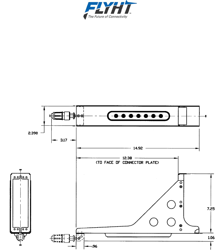
3.1 Data Management Unit
This section describes the mechanical and environmental specifications of the components of
the Data Management Unit (DMU).
3.1.1 General
The DMU is housed in an ARINC 600 2MCU enclosure, which is designed to be mounted in a
standard ARINC 600 mounting tray. See Figure 3-1 for an outline of this component.
Figure 3-1 – DMU Outline Drawing
3.1.2 Mechanical Specifications
Dimensions: 7.81” x 2.27” x 15.02 (See Figure 3-1)
Weight: 7.7 lbs. (3.49 kg.) Max.
Material/Finish: Aluminum Alloy with Blue Polyurethane Finish
Mounting: ARINC 600 2MCU Mounting Tray

AFIRS 228 Series Installation Manual
Confidential and Proprietary to 250-0019
FLYHT Aerospace Solutions Ltd. Rev. --
Page 10 22 April 2013
Rear Mating Connector: Size 2 ARINC 600 Receptacle
Radiall P/N: NSXN2P201S0004
ITT P/N: BKAD2-313-300-04
Maintenance Connector: RJ45 (8P8C) Modular Connector Jack
Flash Card: CompactFlash® (Type I or Type II)
3.1.3 Environmental Specifications – AFIRS 228B
Temperature (Operating): -55°C to +70°C (Without Iridium Satellite Communication)
-40°C to +70°C (With Iridium Satellite Communication)
Temperature (Survival): -55°C to +85°C
Altitude: 55,000 ft.
Vibration: DO-106F Cat. SCL and U2
Humidity: <95% Non-Condensing (DO-106F Cat. A)
DO-160F Categories: [(A2)(F2)X]BAD[(SCL)(U2)]XXXXXXZZ(XI)AZ[ZW][ST]MXXXAC
Note:
Satellite voice and data communications functions in the AFIRS 228B are not operational below
-40°C. At elevated temperatures (>60°C), the voice modem has a maximum duty cycle of 60%.
3.1.4 Environmental Specifications – AFIRS 228S
Temperature (Operating): -55°C to +70°C
Temperature (Survival): -55°C to +85°C
Altitude: 55,000 ft.
Vibration: DO-160G Cat. SCL and U2
Humidity: <95% Non-Condensing (DO-160G Cat. A)
DO-160G Categories: [(A2)(F2)X]BAD[(SCL)(U2)]XXXXXXZZ(XI)AZ[ZW][TT]MXXXAC
Note:
DO-160G Categories for the AFIRS 228S are as specified by the design. Qualification tests on
the AFIRS 228S DMU have not been completed to date.
AFIRS 228 Series Installation Manual
250-0019 Confidential and Proprietary to
Rev. -- FLYHT Aerospace Solutions Ltd.
22 April 2013 Page 11
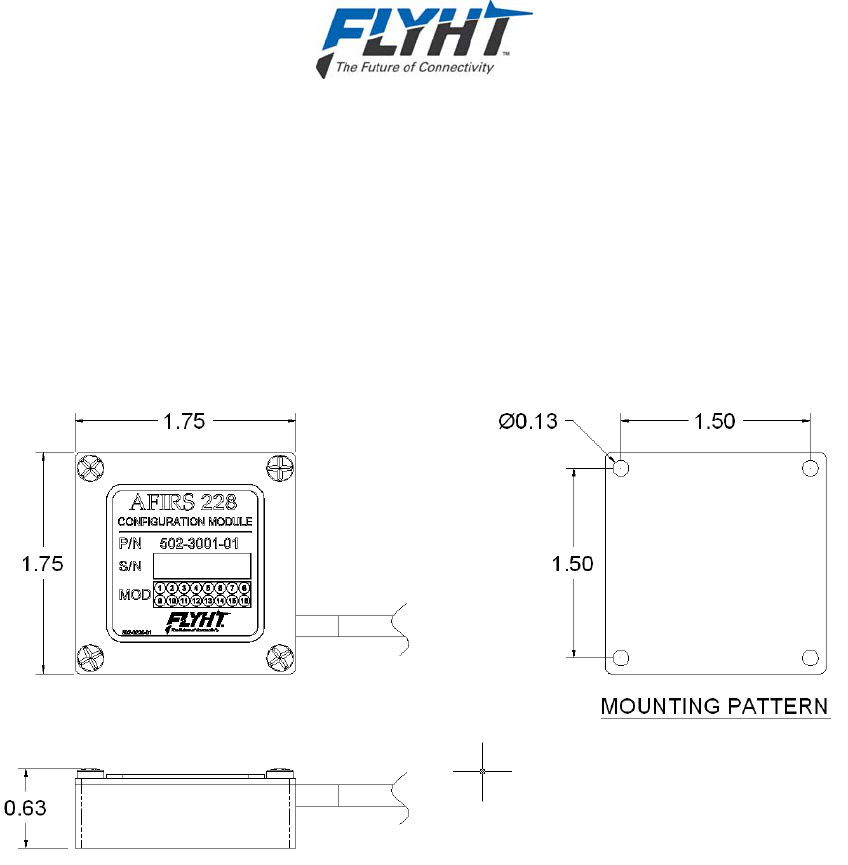
3.2 Aircraft Configuration Module
This section describes the mechanical and environmental specifications of the components of
the Aircraft Configuration Module (ACM).
3.2.1 General
The ACM is housed in small enclosure, which is designed to be mounted within 24” of the DMU
rear connector. Typically, the ACM will be mounted on or near the ARINC 600 mounting tray
used for the DMU. See Figure 3-2 for an outline of this component.
Figure 3-2 – ACM Outline Drawing
3.2.2 Mechanical Specifications
Dimensions: 1.75” x 1.75” x 0.63”
Weight: 0.2 lbs. (0.09 kg.) Max.
Material/Finish: Aluminum Alloy
3.2.3 Environmental Specifications
Temperature (Operating): -55°C to +70°C
Temperature (Survival): -55°C to +85°C
Altitude: 55,000 ft.
Vibration: DO-160F Cat. SCL and U2
Humidity: <95% Non-Condensing (DO-160F Cat. A)
DO-160F Categories: [(A2)(F2)X]BAD[(SCL)(U2)]XXXXXXZZ(XI)AZ[ZW][ST]MXXXAC

AFIRS 228 Series Installation Manual
Confidential and Proprietary to 250-0019
FLYHT Aerospace Solutions Ltd. Rev. --
Page 12 22 April 2013
3.3 AFIRS Antenna
The AFIRS Antenna is to be selected by the system integrator to be suitable for the installed
aircraft environment. FLYHT has evaluated the following antennas and found them to function
properly with the AFIRS 228 system, and generally they will meet most aircraft operating
environments:
Sensor Systems P/N S67-1575-109
Sensor Systems P/N S67-1575-409
Sensor Systems P/N S67-1575-165
Sensor Systems P/N S65-8282-101
Aero Antenna AT2775-110GA
Aero Antenna AT2775-110
When selecting an alternate antenna for use with the AFIRS 228 system, the antenna must
meet the following criteria:
Be suitable for the installed aircraft environmental conditions. Note that in addition to the
temperature, altitude, fluids susceptibility, considerations etc., the antenna must be
approved for the expected aircraft lightning environment.
Be approved by Iridium Communications Inc. as Iridium Certified Equipment (ICE).
Meet the following antenna performance specifications:
Type: Passive – Patch or Helical
Frequency – Iridium: 1616 – 1626.5 MHz
Frequency – GPS: 1575 ±10 MHz
Coverage Volume: 8.2° – 90° Elevation; 360° Azimuth
VSWR (Max.): 1.8:1
Polarization: RHCP
Impedance (Nom.): 50 Ohms
Power Handling (Min.): 20W CW
Gain (Min.): +3 dBic @ Zenith
+0 dBic Weighted Average per DO-262A
If the operator plans to upgrade to the AFIRS 228S in the future, the selected antenna should
be qualified to TSO C-159a so that the system can then be approved for safety services use.
Note:
Proper antenna selection and installation are critical to proper system operation. See §5.3 for
antenna installation criteria and recommendations.

AFIRS 228 Series Installation Manual
250-0019 Confidential and Proprietary to
Rev. -- FLYHT Aerospace Solutions Ltd.
22 April 2013 Page 13
4. INTERFACE SPECIFICATIONS
This section describes the interface specifications of the AFIRS 228 Series system components.
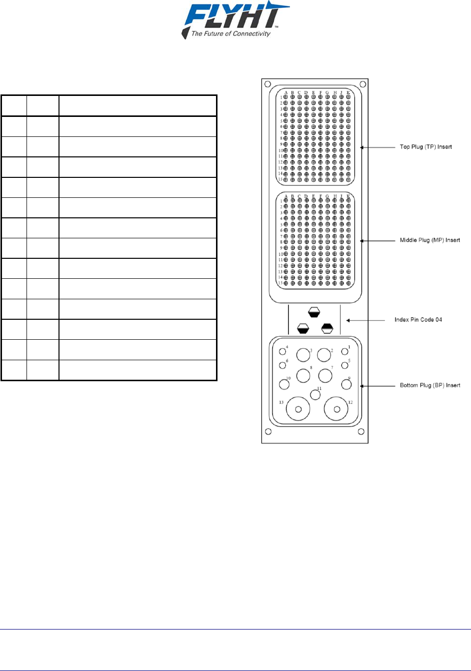
4.1 DMU Rear Connector (J1)
Table 4-1 – J1A Top Plug (TP) Insert
A B C D E F G H J
K
1 Ethernet
1A
Tx+
Ethernet
1A
Rx+
O O
Ethernet
2B
Tx+
Ethernet
2B
Rx+
O O
Ethernet
3B
Tx+
Ethernet
3B
Rx+
2 Ethernet
1A
Rx-
Ethernet
1A
Tx-
O
Ethernet
2B
Rx-
Ethernet
2B
Tx-
O O
Ethernet
3B
Rx-
Ethernet
3B
Tx-
3 O O O O O O O O O O
4 O O O O O O O O O O
5 Ethernet
4B
Tx+
Ethernet
4B
Rx+
O O O O O O O O
6 Ethernet
4B
Rx-
Ethernet
4B
Tx-
O O O O O O O O
7 O O O O O O O O O O
8 O O O O O O O O O O
9 O O O O O O O O O O
10 O O O O O O O O O O
11 O O O O O O O O O O
12 O O O O O O O O O O
13 O O O O O O O O O O
14 O O O O O O O O O O
15 O O O O O O O O O O

AFIRS 228 Series Installation Manual
Confidential and Proprietary to 250-0019
FLYHT Aerospace Solutions Ltd. Rev. --
Page 14 22 April 2013
Table 4-2 – J1B Middle Plug (MP) Insert
A B C D E F G H J
K
1 O O O O O O
No. 1
A429Rx
A
No. 1
A429Rx
B
No. 1
A429Tx
A
No. 1
A429Tx
B
2 Ext. 1
Mic Audio
Hi
Ext. 1
Mic Audio
Lo
Ext. 1
Audio Out
Hi
Ext. 1
Audio Out
Lo
O O O O O O
3 O O
No. 2
A429Rx
A
No. 2
A429Rx
B
No. 3
A429Rx
A
No. 3
A429Rx
B
No. 4
A429Rx
A
No. 4
A429Rx
B
No. 2
A429Tx
A
No. 2
A429Tx
B
4
O
O O O O O O O
ACM
Power
ACM
Ground
5 No. 1
Discrete
Output
WOW 1
Discrete
Input
No. 2
Discrete
Input
No. 3
Discrete
Input
No. 4
Discrete
Input
No. 5
Discrete
Input
No. 6
Discrete
Input
No. 7
Discrete
Input
ACM
Data
ACM
Clock
6 No. 5
A429Rx
A
No. 5
A429Rx
B
No. 6
A429Rx
A
No. 6
A429Rx
B
No. 7
A429Rx
A
No. 7
A429Rx
B
No. 8
A429Rx
A
No. 8
A429Rx
B
No. 9
A429Rx
A
No. 9
A429Rx
B
7 No. 10
A429Rx
A
No. 10
A429Rx
B
No. 3
A429Tx
A
No. 3
A429Tx
B
No. 4
A429Tx
A
No. 4
A429Tx
B
No. 11
A429Rx
A
No. 11
A429Rx
B
No. 1
RS232
Com
No. 4
RS232
Com
8 No. 8
Discrete
Input
No. 2
Discrete
Output
No. 12
A429Rx
A
No. 12
A429Rx
B
No. 3
Discrete
Output
No. 9
Discrete
Input
No. 4
Discrete
Output
No. 10
Discrete
Input
No. 13
A429Rx
A
No. 13
A429Rx
B
9 No. 2
RS232
Com
No. 3
RS232
Com
No. 5
A429Tx
A
No. 5
A429Tx
B
No. 1
RS422Tx-
RS232TXD
No. 1
RS422Tx+
RS232RTS
No. 1
RS422Rx+
RS232RXD
No. 1
RS422Rx-
RS232CTS
No. 2
RS422Tx-
RS232TXD
No. 2
RS422Tx+
RS232RTS
10 No. 2
RS422Rx+
RS232RXD
No. 2
RS422Rx-
RS232CTS
No. 3
RS422Tx-
RS232TXD
No. 3
RS422Tx+
RS232RTS
No. 3
RS422Rx+
RS232RXD
No. 3
RS422Rx-
RS232CTS
No. 4
RS422Tx-
RS232TXD
No. 4
RS422Tx+
RS232RTS
No. 4
RS422Rx+
RS232RXD
No. 4
RS422Rx-
RS232CTS
11 No. 11
Discrete
Input
No. 12
Discrete
Input
No. 13
Discrete
Input
No. 14
Discrete
Input
No. 15
Discrete
Input
WOW
HPP
No. 5
Discrete
Output
No. 6
Discrete
Output
No. 7
Discrete
Output
No. 8
Discrete
Output
12 No. 14
A429Rx
A
No. 14
A429Rx
B
No. 6
A429Tx
A
No. 6
A429Tx
B
A717Rx
A
A717Rx
B
No. 15
A429Rx
A
No. 15
A429Rx
B
No. 16
A429Rx
A
No. 16
A429Rx
B
13 Fault
Output
N/C
Fault
Output
N/O
O O O O O O O O
14 O Chime
Output O O O O O O O O
15 O O O O O O
Phone
Ext. 2
Tip
Phone
Ext. 2
Ring
Phone
Ext. 3
Tip
Phone
Ext. 3
Ring
AFIRS 228 Series Installation Manual
250-0019 Confidential and Proprietary to
Rev. -- FLYHT Aerospace Solutions Ltd.
22 April 2013 Page 15
Table 4-3 – J1C Bottom Plug (BP) Insert
Pin Size Description
1 20 Not Used
2 12 Primary 28 VDC Power Input
3 12 Power Ground
4 20 Not Used
5 20 Remote Start Input
6 20 Not Used
7 12 Not Used
8 12 Chassis Ground
9 16 Alternate 28 VDC Power Input
10 16 Not Used
11 16 Not Used
12 5 Not Used
13 5 Iridium/GPS Antenna
Figure 4-1 – DMU Connector Map
4.1.1 Power Input – Primary and Alternate
Nominal Input: 27.5 VDC
Voltage Range: 18.0 to 32.2 VDC
Input Current – Standby/Data (Typical): 228B: 585 mA (16.1 W)
228S: 640 mA (17.6 W)
Input Current – Voice Call (Typical): 228B: 725 mA (19.9 W)
228S: 725 mA (19.9 W)
Input Current – Max. Cont. (at 32.2 V): 228B: 1.40 A (45.1 W)
228S: 1.20 A (38.6 W)
Recommended Power Control Device: 3 to 5 Amp delayed action circuit breaker
Note:
This is not a floating input. 28 VDC must be applied to the 28 VDC Power input and airframe
ground to Power Ground input.

AFIRS 228 Series Installation Manual
Confidential and Proprietary to 250-0019
FLYHT Aerospace Solutions Ltd. Rev. --
Page 16 22 April 2013
4.1.2 Chassis Ground
For redundant chassis ground connection only. Not to be used as a normal current carrying
conductor.
Quantity: 1
Format: DC Chassis Ground
4.1.3 ARINC 573/717 Digital Serial Bus Input
Quantity: 1
Format: ARINC 573/717, HBP and BPRZ
Data Rate: 64/128/256/512/1024 WPS
4.1.4 ARINC 429 Digital Serial Bus Input
Quantity: 16
Format: DITS, ARINC 429 Low or high speed
Low Speed Data Rate: 12.5 Kbps ± 1%
High Speed Data Rate: 100 Kbps ± 1%
SSM/SDI/Data Definition: Software Selectable Protocols
4.1.5 ARINC 429 Digital Serial Bus Output
Quantity: 6
Format: DITS, ARINC 429 Low or high speed
Low Speed Data Rate: 12.5 Kbps ± 1%
High Speed Data Rate: 100 Kbps ± 1%
SSM/SDI/Data Definition: Software Selectable Protocols
4.1.6 RS-232/422 Digital Serial Bus
Four bi-directional serial ports are provided at the rear connector. Each serial port is individually
software configurable for RS-232 or RS-422, and the following parameters:
Bus Speed (Min.): Up to and Including 19.2 Kbps
Parity: None, Odd, Even
Data Bits: 5, 6, 7, 8
Stop Bits: 1, 2
Flow Control: None, Xon/Xoff, RTS/CTS

AFIRS 228 Series Installation Manual
250-0019 Confidential and Proprietary to
Rev. -- FLYHT Aerospace Solutions Ltd.
22 April 2013 Page 17
When a port is configured to RS-232, it conforms to the ANSI/TIA/EIA-232-F standard. When a
port is configured to RS-422, it conforms to the TIA/EIA-422-B standard with the following
additions:
Cable termination not required for typical applications (See TIA/EIA-422-B Annex A)
Maximum Transceivers on Bus: 20
Receiver Input Impedance: 12 KΩ
4.1.7 Ethernet
Quantity: 4
Format: 802.3 10BASE-T/100BASE-TX, half- and full-
duplex modes (auto-negotiated)
ARINC 664P2 Physical Layer
4.1.8 Discrete Inputs
Quantity: 16 Configurable
Input Impedance: >10 kΩ
Fault Current: <15 mA
DIN+ Voltage Range: Logic High: 7.0 – 36.0 VDC
Logic Low: 0 – 3.5 VDC
Pulse Width (Min): 100 ms
4.1.8.1 Configurable Inputs
Each configurable discrete input is individually software-configurable for the following:
Signal Level: Open-Ground (Negative-Seeking) or Open-28V (Positive-Seeking)
Logic Assignment: Active Low or Active High
Function: Selected from list.
Refer to §7.13 for additional information on use of configurable inputs.
4.1.8.2 Remote Start Input
In addition to the configurable discrete inputs, a Remote Start discrete input (J1C-5) is provided
as a Negative-Seeking (Open/Ground) Active Low input with appropriate internal pull-up
functionality. Refer to §7.3 for a description of the Remote Start functions.
4.1.9 Discrete Outputs
Each discrete output transitions between an ‘Open Circuit’ (high-impedance-to-ground) and a
‘Closed Circuit’ (low-impedance-to-ground) state to indicate a change in output logic.
Quantity: 8 Configurable
‘Open Circuit’ Impedance: >100 kΩ
‘Open Circuit’ Voltage (Max.): 36 VDC

AFIRS 228 Series Installation Manual
Confidential and Proprietary to 250-0019
FLYHT Aerospace Solutions Ltd. Rev. --
Page 18 22 April 2013
‘Closed Circuit’ Current Limit (Min.): 500 mA
Voltage Across ‘Closed Circuit’: <1.25 V
4.1.9.1 Configurable Outputs
The Discrete Outputs use ‘Open-Closed’ signal levels, where the output is either high-
impedance to ground (Open) or low-impedance to ground (Closed). Each configurable discrete
output is individually software-configurable for the following:
Logic Assignment: Active Low (Closed) or Active High (Open)
Function: Selected from list.
Refer to §7.14 for additional information on use of configurable outputs.
4.1.9.2 Fault Output
The FAULT output is assigned to two rear connector pins, each meeting the same electrical
criteria as a configurable output with the following functions:
The Normally Closed (N/C) FAULT output (J1B-13A) is “Closed Circuit to Ground” whenever
any system fault is identified, including when the system is not powered.
The Normally Open (N/O) FAULT output (J1B-13B) is “Open Circuit” (high impedance)
whenever any system fault is identified, including when the system is not powered.
4.1.9.3 Chime Output
The CHIME output goes to the “Closed Circuit to Ground” active state whenever the system is
providing an aural alert in the cockpit (e.g. incoming voice call). The CHIME output is assigned
to one aircraft interface connector pin (J1B-14B) meeting the following criteria:
‘Open Circuit’ Impedance: >100 kΩ
‘Open Circuit’ Voltage (Max.): 36 VDC
‘Closed Circuit’ Current Limit (Min.): 2 A
Voltage Across ‘Closed Circuit’: <1.25 V
4.1.10 Two-Wire Phone
Quantity: 2
Format: Standard 2-Wire Tip and Ring Loop
Loop Battery: 48 ±4 VDC
Ring Signal: 20 Hz ±10%, 90 ±10 VAC RMS
Hook Flash: <700 ms
Load Impedance (Nom.): 600 Ω
Polarity Sensitivity: None
Audio Band Pass: 300 – 3400 Hz

AFIRS 228 Series Installation Manual
250-0019 Confidential and Proprietary to
Rev. -- FLYHT Aerospace Solutions Ltd.
22 April 2013 Page 19
4.1.11 Microphone Input
Quantity: 1
Format: Standard DO-214 Microphone Input
Dynamic Range: 20 mV to 1.5 V RMS
Input Impedance: 150 Ω ± 20%
Mic. Bias (No Load): 16 ± 0.5 V
Mic. Bias Ripple: <1 mV RMS in the 300 – 3400 Hz band
Sidetone: Provided by System to Interphone Output
Sidetone Level: Software Configurable
Audio Band Pass: 300 – 3400 Hz
4.1.12 Interphone Output
Quantity: 1
Format: Standard DO-214 Interphone Output
Rated Output Impedance: <30 Ω across the frequency range
250 Ω without system powered
Rated Load Impedance: 50 Ω across the frequency range
(capable of driving unbalanced load)
Output Power Capability: >40 mW RMS into 600 Ω
(software adjustable from 0.1 mW to max.)
>210 mW RMS into 50 Ω
Output Power (As Shipped): 10 mW RMS into 600 Ω
Audio Band Pass: 300 – 3400 Hz
4.1.13 Iridium and GPS Antenna
Coaxial Cable Insertion Loss (Max.): 3 dB @ 1626.5 MHz
4.2 DMU Maintenance Connector (J2)
The AFIRS DMU provides an RJ-45 Maintenance Port connector on the front panel which
provides for Ethernet connection to Ground Service Equipment (GSE) e.g. a laptop or Personal
Computer with a standard web browser.
AFIRS 228 Series Installation Manual
Confidential and Proprietary to 250-0019
FLYHT Aerospace Solutions Ltd. Rev. --
Page 20 22 April 2013
4.3 Aircraft Configuration Module
The ACM provides a 24-inch, color-coded, 4-conductor flying lead, which is terminated at the
DMU rear connector (J1B) as per the following table:
Table 4-4 – ACM Connections
Color Function Termination – J1B (MP)
Orange/Violet ACM Power 4J
Violet ACM Ground 4K
Green/Violet ACM Data 5J
Blue/Violet ACM Clock 5K
4.4 ARINC 429 Receiver Protocols
4.4.1 ACARS Communications Management Unit
Source: ARINC 758 CMU Speed: Configurable
Label Parameter Format Transmit Rate Core
172 Subsystem Identifier SAL 1 s
214 ICAO 24-Bit Aircraft Address Word 1 DISC 1 s
216 ICAO 24-Bit Aircraft Address Word 2 DISC 1 s
270 Status Output 1 DISC 1 s
276 Status Output 2 DISC 1 s
377 Equipment Identifier BCD 1 s
4.4.2 Airbus Centralized Fault Display System (CFDS)
Source: CFDIU Speed: Configurable (Lo)
Label Parameter Format Transmit Rate Core
125 Time BCD 1 s
126 Flight Phase BNR 1 s
155 Aircraft Configuration DISC 1 s
156 Aircraft Type DISC 1 s
157 Aircraft Options DISC 1 s
233 Flight Number 1, 2 BNR/BCD 4 s (SA)1
5 s (LR)

AFIRS 228 Series Installation Manual
250-0019 Confidential and Proprietary to
Rev. -- FLYHT Aerospace Solutions Ltd.
22 April 2013 Page 21
4.4.2 Airbus Centralized Fault Display System (CFDS)
Source: CFDIU Speed: Configurable (Lo)
Label Parameter Format Transmit Rate Core
234 Flight Number 3, 4 BNR/BCD 4 s (SA)1
5 s (LR)
235 Flight Number 5, 6 BNR/BCD 4 s (SA)1
5 s (LR)
236 Flight Number 7, 8 BNR/BCD 4 s (SA)1
5 s (LR)
237 Flight Number 9,10 BNR/BCD 5 s (LR)1
260G Date BCD 1 s
301 Aircraft Identification 1-3 ISO 5 4 s
302 Aircraft Identification 4-6 ISO 5 4 s
303 Aircraft Identification 7-9 ISO 5 4 s
304 Fleet Identification, Aircraft Type ISO 5 4 s
Notes:
1. Airbus Single Aisle (SA) aircraft transmit Labels 233-236 every 4 seconds. Airbus Long Range (LR)
aircraft transmit Labels 233-237 every 5 seconds.
4.4.3 Flight Management System – ARINC 702/A
Source: ARINC 702/A FMC Speed: Configurable
Label Parameter Format Transmit Rate Core
010 Present Position – Latitude BCD 500 ms 2
011 Present Position – Longitude BCD 500 ms 2
012 Ground Speed BCD 500 ms 2
013 Track Angle – True BCD 500 ms
015 Wind Speed BCD 500 ms
016 Wind Direction – True BCD 500 ms
061 Departure/Destination Airports (Dep1,2,3) BNR 1 s
062 Departure/Destination Airports (Dep4/Des1) BNR 1 s
063 Departure/Destination Airports (Des2,3,4) BNR 1 s
074 Zero Fuel Weight BNR 1 s
075 Gross Weight BNR 200 ms
125 Universal Coordinated Time (UTC) BCD 200 ms 2

AFIRS 228 Series Installation Manual
Confidential and Proprietary to 250-0019
FLYHT Aerospace Solutions Ltd. Rev. --
Page 22 22 April 2013
4.4.3 Flight Management System – ARINC 702/A
Source: ARINC 702/A FMC Speed: Configurable
Label Parameter Format Transmit Rate Core
150 Universal Coordinated Time (UTC) BNR 200 ms 2
206 Computed Airspeed BNR 125 ms
211 Total Air Temperature BNR 500 ms
213 Static Air Temperature BNR 500 ms
233 Flight Number (Characters 1,2) BNR/BCD 1 s
234 Flight Number (Characters 3,4) BNR/BCD 1 s
235 Flight Number (Characters 5,6) BNR/BCD 1 s
236 Flight Number (Characters 7,8) BNR/BCD 1 s
237 Flight Number (Characters 9,10) BNR/BCD 1 s
2601 Date / Flight Leg BCD 1 s
261 Flight Number BCD 1 s
270 Status Discretes DISC 200 ms
310 Present Position – Latitude BNR 200 ms 2
311 Present Position – Longitude BNR 200 ms 2
312 Ground Speed BNR 50 ms 2
313 Track Angle – True BNR 50 ms
314 True Heading BNR 50 ms
315 Wind Speed BNR 100 ms
316 Wind Direction – True BNR 50 ms
317 Track Angle – Magnetic BNR 50 ms
320 Magnetic Heading BNR 50 ms
360 Flight Information BNR 1 s
Notes:
1. Because of the potential conflict between systems that could output either the year or the flight leg
number in this word, only the day and month portions of the date are used.
2. Either the BNR or BCD label (not both) is required for Latitude, Longitude, Groundspeed and UTC.

AFIRS 228 Series Installation Manual
250-0019 Confidential and Proprietary to
Rev. -- FLYHT Aerospace Solutions Ltd.
22 April 2013 Page 23
4.4.4 Flight Management System – GAMA 429
Source: GAMA 429 FMC Speed: Configurable
Label1 Parameter Format Transmit Rate Core
012 Ground Speed BCD 500 ms 4
074G Data Record Header BNR Note 2
075G Active WPT From/To Data DISC Note 2
113G Message Checksum BNR Note 3
125 Universal Coordinated Time (UTC) BCD 200 ms 4
150 Universal Coordinated Time (UTC) BNR 100 ms 4
203 Pressure Altitude BNR 1 s
204 Baro Corrected Altitude BNR 62.5 ms
210 True Airspeed BNR 125 ms
213 Static Air Temperature BNR 500 ms
260G Date BCD 1 s
275G Status Word DISC 400 ms
300G Station Magnetic Dec. Type & Class BNR Note 3
301G Message Characters 7-9 BNR Note 3
302G Message Characters 10-12 BNR Note 3
303G Message Length / Type / Number BNR Note 3
304G Message Characters 1-3 BNR Note 3
305G Message Characters 4-6 BNR Note 3
306G NAV/WPT/AP Latitude BNR Note 3
307G NAV/WPT/AP Longitude BNR Note 3
310 Present Position – Latitude BNR 200 ms
311 Present Position – Longitude BNR 200 ms
312 Ground Speed BNR 50 ms 4
313 Track Angle – True BNR 50 ms
314 True Heading BNR 50 ms
315 Wind Speed BNR 100 ms
316 Wind Direction – True BNR 100 ms
320 Magnetic Heading BNR 50 ms
352G Estimated Time to Destination BNR 1 s
371G Equipment Identifier DISC 1 s

AFIRS 228 Series Installation Manual
Confidential and Proprietary to 250-0019
FLYHT Aerospace Solutions Ltd. Rev. --
Page 24 22 April 2013
4.4.4 Flight Management System – GAMA 429
Notes:
1. Labels with a “G” suffix are defined in GAMA Publication No. 11.
2. These labels are transmitted once at the beginning of each flightplan/graphics map data transfer. Refer
to GAMA Publication No. 11 for further information.
3. These labels are used to make up the individual records that comprise a flightplan/graphics map data
transfer. Not all labels are transmitted with each record. Ten records are transmitted in one second.
Refer to GAMA Publication No. 11 Addendum 3 for further information.
4. Either the BNR or BCD label (not both) is required for Groundspeed and UTC.
4.4.5 Flight Management System – CMA-9000
Source: FMC – General Broadcast Output Bus Speed: Configurable
Label Parameter Format Transmit Rate Core
056 ETA – At Destination BCD 1 s
061 Departure/Destination Airports (Dep1,2,3) BNR 1 s
062 Departure/Destination Airports (Dep4/Des1) BNR 1 s
063 Departure/Destination Airports (Des2,3,4) BNR 1 s
074 Zero Fuel Weight BNR 1 s
075 Gross Weight BNR 1 s
076 GPS Altitude BNR 1 s
150 Universal Coordinated Time (UTC) BNR 500 ms
203 Pressure Altitude BNR 500 ms
204 Baro Corrected Altitude BNR 500 ms
205 Mach Number BNR 1 s
206 Computed / Indicated Airspeed BNR 1 s
210 True Airspeed BNR 500 ms
213 Static Air Temperature BNR 1 s
233 Flight Number (Characters 1,2) BNR/BCD 1 s
234 Flight Number (Characters 3,4) BNR/BCD 1 s
235 Flight Number (Characters 5,6) BNR/BCD 1 s
236 Flight Number (Characters 7,8) BNR/BCD 1 s
237 Flight Number (Characters 9,10) BNR/BCD 1 s
260 Date / Flight Leg BCD 1 s
261 Flight Number BCD 1 s

AFIRS 228 Series Installation Manual
250-0019 Confidential and Proprietary to
Rev. -- FLYHT Aerospace Solutions Ltd.
22 April 2013 Page 25
4.4.5 Flight Management System – CMA-9000
Source: FMC – General Broadcast Output Bus Speed: Configurable
Label Parameter Format Transmit Rate Core
270 FMS Status Word 1 DISC 1 s
310 Present Position – Latitude BNR 500 ms
311 Present Position – Longitude BNR 500 ms
312 Ground Speed BNR 500 ms
313 Track Angle – True BNR 500 ms
314 True Heading BNR 500 ms
315 Wind Speed BNR 500 ms
316 Wind Direction – True BNR 500 ms
317 Track Angle – Magnetic BNR 500 ms
320 Magnetic Heading BNR 500 ms
4.4.6 Basic DTP
Source: Generic Date/Time/Position Source Speed: Configurable
Label Parameter Format Transmit Rate Core
150 Universal Coordinated Time (UTC) BNR 1 s
260G Date BCD 1 s
310 Present Position – Latitude BNR 200 ms
311 Present Position – Longitude BNR 200 ms
4.4.7 Pro Line 4/21 – I/O Concentrator (GP Bus 5)
Source: IOC – GPBUS 5 Speed: High
Label Parameter Format Transmit Rate Core
151 Universal Coordinated Time (UTC) BNR 1 s
203 Pressure Altitude BNR 50 ms
205 Mach Number BNR 100 ms
206 Computed / Indicated Airspeed BNR 50 ms
211 Total Air Temperature BNR 400 ms
261 Date BCD 1 s
310 Present Position – Latitude BNR 200 ms

AFIRS 228 Series Installation Manual
Confidential and Proprietary to 250-0019
FLYHT Aerospace Solutions Ltd. Rev. --
Page 26 22 April 2013
4.4.7 Pro Line 4/21 – I/O Concentrator (GP Bus 5)
Source: IOC – GPBUS 5 Speed: High
Label Parameter Format Transmit Rate Core
311 Present Position – Longitude BNR 200 ms
312 Ground Speed BNR 200 ms
313 Track Angle – True BNR 100 ms
314 True Heading BNR 100 ms
315 Wind Speed BNR 500 ms
320 Magnetic Heading BNR 19 ms
4.4.8 Multi-Purpose Control Display Unit
Source: ARINC 739A MCDU Speed: Configurable
Label Parameter Format Transmit Rate Core
270 MCDU Normal Discrete Word DISC 1 s
377 Equipment Identifier DISC 1 s
4.4.9 Mode S Transponder
Source: ARINC 718A Mode S Transponder Speed: Configurable
Label Parameter Format Transmit Rate Core
203 Altitude BNR 100 ms
204 Baro Corrected Altitude BNR 100 ms
233 Flight ID (Characters 1,2) BNR/BCD 1 s
234 Flight ID (Characters 3,4) BNR/BCD 1 s
235 Flight ID (Characters 5,6) BNR/BCD 1 s
236 Flight ID (Characters 7,8) BNR/BCD 1 s
237 Flight ID (Characters 9,10) BNR/BCD 1 s
275 TCAS Control (Mode S Address Part 1) DISC 100 ms
276 TCAS Control (Mode S Address Part 2) DISC 100 ms

AFIRS 228 Series Installation Manual
250-0019 Confidential and Proprietary to
Rev. -- FLYHT Aerospace Solutions Ltd.
22 April 2013 Page 27
4.5 ARINC 429 Receiver Activity Status
Table 4-5 defines the criteria the AFIRS 228 Series uses for determining whether a receiver port
is active. A bus is generally declared active when 4 consecutive words at the specified rate are
received and declared inactive when 4 consecutive samples fail.
Table 4-5 – ARINC 429 Receiver Port Monitoring
Receiver Activity Label Min. Update Rate
ACARS 270 1 Hz
Airbus CFDS 125 / 260 1 Hz
FMS (A702/A, CMA-9000) 270 / 275 1 Hz
FMS (GAMA 429) 275 1 Hz
Basic DTP 310 / 311 1 Hz
PL4/21 GPBus5 310 / 311 1 Hz
A739 MCDU 270 / 377 1 Hz
Mode S Transponder 275 1 Hz
4.6 ARINC 429 Transmitter Protocols
4.6.1 ACARS Output Bus
Destin: ARINC 758 CMU Speed: Configurable
Label Parameter Format Transmit Rate Update Rate
172 Subsystem Identifier SAL 1 s –
270 Status Word DISC 1 s 1 s
4.6.2 General Purpose Output Bus
Destin: Various Speed: Configurable
Label Parameter Format Transmit Rate Update Rate
172 Subsystem Identifier SAL 1 s –
270 Status Word DISC 1 s 1 s
377 Equipment Identifier BCD 1 s –
AFIRS 228 Series Installation Manual
Confidential and Proprietary to 250-0019
FLYHT Aerospace Solutions Ltd. Rev. --
Page 28 22 April 2013
4.6.3 A739 MCDU Output Bus
Destin: ARINC 739A MCDU Speed: Configurable
Label Parameter Format Transmit Rate Update Rate
172 Subsystem Identifier SAL 1 s –
377 Equipment Identifier BCD 1 s –
4.6.4 Airbus Centralized Fault Display System (CFDS) Output Bus
Destin: Airbus CFDIU Speed: Configurable
Label Parameter Format Transmit Rate Update Rate
354 LRU Identification ISO-5 500 ms –
3561 Fault Status ISO-5 200 ms 1 s
377 Equipment Identifier BCD 1 s –
Notes:
1. Label 356 is only transmitted when the system is in Operational or Maintenance mode and there are
no active failures or faults.
AFIRS 228 Series Installation Manual
250-0019 Confidential and Proprietary to
Rev. -- FLYHT Aerospace Solutions Ltd.
22 April 2013 Page 29
5. INSTALLATION CONSIDERATIONS
This section provides information on the installation considerations for each of the AFIRS 228
Series system components.
5.1 Data Management Unit (DMU)
The DMU is housed in an ARINC 600 2MCU enclosure, which is designed to be mounted in a
standard ARINC 600 mounting tray. Figure 5-1 shows a typical ARINC 600 2MCU tray used for
the AFIRS DMU.
Figure 5-1 – 2MCU Mounting Tray
While the DMU does not require forced-air cooling, every attempt should be made to place the
DMU in a benign and well-ventilated environment. Placing the DMU on a plenum shelf in the
Electronics Bay of the aircraft and using a mounting tray that provides cooling air to the DMU is
preferred.
The DMU tray should be electrically bonded to the airframe (<10 milliohms). It is recommended
that the DMU be located where easy front panel access is available to facilitate replacing the
flash card or connecting to the Maintenance Port.

AFIRS 228 Series Installation Manual
Confidential and Proprietary to 250-0019
FLYHT Aerospace Solutions Ltd. Rev. --
Page 30 22 April 2013
5.2 Aircraft Configuration Module (ACM)
The ACM can be mounted on or near the DMU tray within 24 inches of the DMU rear connector.
The ACM should be electrically bonded to the airframe (<10 milliohms). It is recommended that
the ACM be located to provide easy access to the cover if ever the SIM card requires
replacement. Refer to Figure 3-2 for the ACM mounting footprint.
5.3 AFIRS Antenna System
The AFIRS 228 Series system has a single combined Iridium/GPS RF connection on the rear
interface connector, which is to be connected to a single combined Iridium/GPS Antenna. The
antenna system is comprised of all the components from the rear interface connector up to and
including the antenna. The total gain of the antenna system must be greater than 0 dB at
1626.5 MHz (measured at the antenna zenith).
Most Iridium antennas have a gain of +3 dBic at the zenith; therefore the maximum attenuation
in the rest of the antenna system must be less than 3 dB. If an antenna with a different gain is
selected, the maximum loss of the rest of the antenna system must be adjusted accordingly.
5.3.1 Antenna
The antenna is to be selected by the system integrator to be suitable for the installed aircraft
environment. See §3.3 for antenna selection criteria.
5.3.2 Antenna Location
The antenna must be mounted in a location with a clear view of the sky. The typical mounting
location is on top of the fuselage as close to the AFIRS DMU as possible.
The AFIRS antenna should be kept a minimum of 5 feet from GPS antennas and a minimum of
3 feet from all other antennas, unless analyses and tests demonstrate that there is no mutual
interference when separation is reduced.
If the aircraft is equipped with a high-gain INMARSAT Satcom system (e.g. Aero-I, Aero-H,
etc.), the separation between the high-gain INMARSAT antenna and the AFIRS antenna must
be maximized, preferably >45 feet. Typically, a filter is also required to mitigate the interference
from the INMARSAT system (ref. §5.3.5).
If the aircraft is equipped with a low-gain INMARSAT Satcom system (e.g. Aero-C, Sat-AFIS,
etc.), the separation between the low-gain INMARSAT antenna and the AFIRS antenna should
be at least 10 feet. Typically, a filter is also required to mitigate the interference from the
INMARSAT system (ref. §5.3.5).
5.3.3 Antenna Mounting
The system integrator is responsible to mount the antenna to the airframe using methods that
meet all of the applicable airworthiness requirements. If the antenna is mounted off the
centerline of the fuselage (e.g. to avoid a stringer) or on a surface that is not parallel with the
longitudinal axis of the aircraft (e.g. a fairing), a shim should be used to keep the antenna tilt
angle to 5° or less in both the lateral and longitudinal axes for optimal performance.
The antenna must be installed in a manner that prevents harmful levels of lightning energy from
entering the AFIRS system through the coaxial cable. This is can be accomplished by selecting

AFIRS 228 Series Installation Manual
250-0019 Confidential and Proprietary to
Rev. -- FLYHT Aerospace Solutions Ltd.
22 April 2013 Page 31
an antenna that has been tested for direct lightning effects in accordance with DO-160, and then
electrically bonding the antenna to the airframe (<10 milliohms).
For metal airframes, this can be accomplished by direct metal-to-metal contact between the
antenna, the mounting shim (if used) and the airframe. The airframe structure should not be
painted, and fay sealing should not be used between the antenna, the shim, and airframe. For
mounting on non-metallic fairings, a low-impedance ground plane (minimum 6-inches wide)
should be provided to the adjacent metallic structure.
For composite airframes, refer to the airframe manufacturer’s instructions for acceptable
methods to install the AFIRS antenna.
5.3.4 Coaxial Cable
The coaxial cable used between the rear interface connector and the antenna is a critical
component of the antenna system. The coaxial cable must meet all the environmental and
flammability requirements applicable to the Electrical Wiring Interconnection System (EWIS) of
the given aircraft. It must also minimize signal attenuation.
Large diameter low-loss cables cannot be connected directly to the ARINC 600 Size 5 contact
on the AFIRS rear electrical connector, so a stub coaxial cable is often required. Shelf
disconnect panels on modern transport category aircraft provide a convenient location to
transition from the stub coaxial cable to the low-loss cable. It is recommended that cable breaks
be kept to a minimum, as each connection typically adds approximately 0.1 dB of insertion loss.
FLYHT recommends the following coaxial cable types be used in aircraft installations. Alternate
cables and connectors that meet the attenuation and EWIS requirements are also acceptable.
Table 5-1 – Coaxial Cable Types
Cable
Part Number Vendor Attenuation
(dB/100 ft) Size 5
Contact TNC
Bulkhead TNC
Connector 90° TNC
Connector
310701 ECS 3.9 — BTS002 CTS002 CTR002
310801 ECS 4.6 — BTS022 CTS022 CTR022
311201 ECS 6.7 — BTS122 CTS122 CTR122
311501 ECS 9.1 P922 BTS922 CTS922 CTR922
S22089 PIC 4.5 — 190421 190409 190408
S55122 PIC 6.6 — 190621 190609 190608
S33141 PIC 8.6 190303 190321 190308 190309

AFIRS 228 Series Installation Manual
Confidential and Proprietary to 250-0019
FLYHT Aerospace Solutions Ltd. Rev. --
Page 32 22 April 2013
Cable
Part Number Vendor Attenuation
(dB/100 ft) Size 5
Contact TNC
Bulkhead TNC
Connector 90° TNC
Connector
TFLX480-100 Emteq 4.8 — TFS488-2 TMS488-1 TMR488-1
TFLX410-100 Emteq 5.2 — TFS410-2 TMS410-1 TMR410-1
TFLX295-100 Emteq 7.6 — TFS295-2 TMS295-1 TMR295-1
TFLX165-100 Emteq 17.0 A65165-1 TFS165-2 TMS165-1 TMR165-1
For example, a cable installation consisting of a P922 contact, 2 feet of 311501 cable, a
BTS922 connector mated to a CTS022 connector, 30 feet of 310801 cable, and a CTR022
connector would result in:
0.10 + 0.18 + 0.10 + 1.38 + 0.10 = 1.86 dB attenuation
FLYHT recommends that every effort be made to minimize cable attenuation, as this improves
the link margin and performance of the satellite system. When the aircraft is also equipped with
an INMARSAT Satcom system, keeping the antenna system attenuation below 2.0 dB (1.0 dB
for the filter and 1.0 dB for the coaxial cable) significantly improves the mitigation of
interference.
5.3.5 INMARSAT Filter
When the aircraft is also equipped with an INMARSAT Satcom system, a filter is generally
required to be installed in the AFIRS antenna system to mitigate the interference from the
INMARSAT system. These filters generally have an insertion loss of 1.0 – 1.2 dB and this must
be taken into account in the total antenna system attenuation calculation.
Due to the complexities associated with concurrent Iridium and INMARSAT system installations,
FLYHT recommends that system integrators who are planning these types of installations
contact FLYHT’s Engineering Department for guidance and assistance.

AFIRS 228 Series Installation Manual
250-0019 Confidential and Proprietary to
Rev. -- FLYHT Aerospace Solutions Ltd.
22 April 2013 Page 33
6. INSTALLATION MATERIALS
In addition to the AFIRS 228 Series LRUs (DMU and ACM), the materials described in this
section are generally required as part of a typical AFIRS 228 Series system installation.
Note:
The system integrator is responsible to ensure that all installation materials used meet the
regulatory requirements for the intended aircraft installation environment.
6.1 Required Materials
ARINC 600 2MCU mounting tray
ARINC 600 Size 2 connector, with contacts
ARINC 600 ground block, with contacts
AFIRS antenna (ref. §3.3)
Antenna coaxial cable(s) (ref. §5.3.4)
System interface wiring (ref. §7)
The following table provides typical part numbers for installation materials.
Table 6-1 – Installation Materials
Description Part Number Vendor Qty.
Mounting Tray, No Cooling 6012-102 ECS 1
Mounting Tray, Plenum 6064-102
Connector, ARINC 600 NSXN2P201S0004
Radiall 1
Connector1, ARINC 600,
With #6-32 Clinch Nuts
NSXN2P201S0104
Contact, #12 Reduced Barrel 620 341 Radiall 5
Contact, ARINC 600 Size 5 P922 ECS 1
Ground Block1, ARINC RBGP48-116N (Souriau)
S280W601-116 (Boeing)
Burndy
(Souriau) 1
Contact, Ground Block M39029/1-101 – 50
Notes:
1. Connector with clinch nuts cannot be used in conjunction with ARINC ground
block.

AFIRS 228 Series Installation Manual
Confidential and Proprietary to 250-0019
FLYHT Aerospace Solutions Ltd. Rev. --
Page 34 22 April 2013
6.2 Additional Materials
Depending on the architecture of the systems being interfaced to, the following materials may
be required.
AFIRS FAULT Annunciator (ref. §7.4)
AFIRS Status Annunciators (ref. §7.14 and §7.15)
AFIRS Control Switches (ref. §7.13 and §7.15)
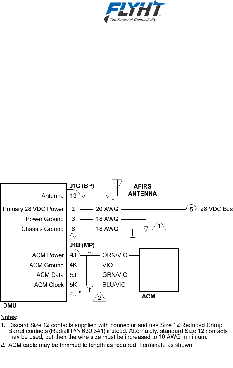
AFIRS 228 Series Installation Manual
250-0019 Confidential and Proprietary to
Rev. -- FLYHT Aerospace Solutions Ltd.
22 April 2013 Page 35
7. SYSTEM INTERFACE WIRING
This section provides information on the system interface wiring required for the AFIRS 228
Series System.
7.1 General
All wire types and installation practices must comply with the EWIS requirements for the aircraft
(ref. FAR 26 Subparts B & D). Unless otherwise noted, minimum wire size is 22 AWG for
standard copper wire or 24 AWG for high strength copper alloy wire.
Terminate all shields at ground block or ground stud on DMU tray. Keep shield drains and
unshielded conductor lengths as short as practicable (<3”).
7.2 Primary Power, Antenna, and ACM
The primary power, antenna, and ACM connections shown in Figure 7-1 are required for all
AFIRS 228 system installations. The system will start and continue to operate whenever power
(20.5 – 32.2 VDC) is available at the Primary Power Input pin (J1C-2).
Figure 7-1 – Primary Power, Antenna and ACM Interface
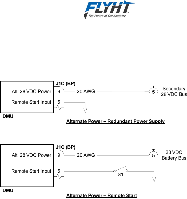
AFIRS 228 Series Installation Manual
Confidential and Proprietary to 250-0019
FLYHT Aerospace Solutions Ltd. Rev. --
Page 36 22 April 2013
7.3 Alternate Power
Alternate Power and Remote Start are optional connections (see Figure 7-2). When power is
applied to the Alternate Power Input pin (J1C-9) and the Remote Start Input pin (J1C-5) is held
in the Active Lo state for >100 ms, the system will run on the Alternate Power. If both the
Primary and Alternate power sources are available, the system will use the Primary Power
Input.
Figure 7-2 – Alternate Power Interface
7.3.1 Redundant Power Supply
One use of the Alternate Power Input is to provide redundant power supply to the AFIRS
system. In this scenario, the Primary Power Input can be connected to a 28 VDC Main Bus and
the Alternate Power Input connected to a Secondary Bus, Battery Bus, or dedicated AFIRS
battery pack. The Remote Start Input is connected to ground. The AFIRS will operate on the
Primary Power Input, but if Primary Power is lost, the system will continue to operate from the
Alternate Power Input.
A software-configurable timer can be used to automatically shut the AFIRS system down after a
specified time (0 – 30 minutes). The timer can also be set to “Always On”.
7.3.2 Remote Start
Another use of the Alternate Power Input is to provide remote start capability to the AFIRS
system. In this scenario, the Primary Power Input can be connected to a 28 VDC Main Bus and
the Alternate Power Input connected to a Battery Bus or dedicated AFIRS battery pack. When a
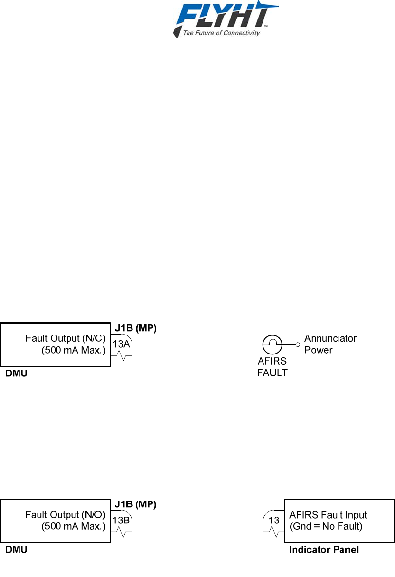
AFIRS 228 Series Installation Manual
250-0019 Confidential and Proprietary to
Rev. -- FLYHT Aerospace Solutions Ltd.
22 April 2013 Page 37
momentary ground (<100 ms) is applied to the Remote Start Input, the system will start and
operate from the Alternate Power Input.
The software-configurable timer can be used to automatically turn the system off if Primary
Power is not provided in the specified time. One use of this configuration is to monitor Auxiliary
Power Unit (APU) start times. If the Remote Start Input is connected to the APU start logic, the
AFIRS will start when the APU starts. Even if the main aircraft power is not turned on, the
AFIRS can log the APU start event and advise operators if an APU is left running for an
extended time.
7.4 Fault Indicator
The system integrator should provide an AFIRS FAULT indication in the cockpit. This may be
provided by an ARINC 429 interface to a centralized crew alerting system, or by using a discrete
Fault output from the AFIRS. The AFIRS 228 provides two separate fault outputs, a normally
closed (N/C) and a normally open (N/O).
7.4.1 Fault Output (N/C)
The N/C fault output provides a ground whenever there is a system fault, including if the system
is not powered. This is the preferred output for most installations. See Figure 7-3.
Figure 7-3 – Fault (N/C) Interface
7.4.2 Fault Output (N/O)
The N/O fault output provides an open circuit whenever there is a system fault, including if the
system is not powered, and provides a ground when there is no fault. This interface is primarily
intended for backwards compatibility for retrofit of existing AFIRS 220 systems. See Figure 7-4.
Figure 7-4 – Fault (N/O) Interface
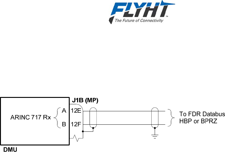
AFIRS 228 Series Installation Manual
Confidential and Proprietary to 250-0019
FLYHT Aerospace Solutions Ltd. Rev. --
Page 38 22 April 2013
7.5 Flight Data Monitoring
The AFIRS 228 may be connected to an ARINC 573/717 databus in the aircraft for monitoring
and recording information on this databus. This interface is software-configurable to support 64,
128, 256, 512, and 1024 WPS data rates, as well as Harvard Bi-Phase or Bipolar-Return-To-
Zero encoding. See Figure 7-5.
Figure 7-5 – ARINC 717 Interface
7.6 ARINC 429 Interfaces
The AFIRS 228 has 16 ARINC 429 receive ports and 6 ARINC 429 transmit ports. Each port is
software-configurable for high or low speed, and the receive ports are also individually software-
configurable for odd, even or no parity checking. (The transmit ports always transmit odd parity.)
7.6.1 Receiver Protocols
Each of the ARINC 429 receivers can be configured in software for the proper protocol of the
external aircraft system to which it is interfaced. Below is a list of the available ARINC 429
receiver protocols. (See §4.4 for the label specifications for each receiver protocol.) Once a
protocol (except “None” or “Generic 429”) is selected for any given receive port, it is no longer
available for assignment to any of the other ports.
None
Generic 429
ACARS 1
ACARS 2
Airbus CFDS
FMS 1 – A702/A, GAMA 429, CMA-9000, Basic DTP
FMS 2 – A702/A, GAMA 429, CMA-9000, Basic DTP
FMS 3 – A702/A, GAMA 429, CMA-9000
PL4/21 GPBUS5 1
PL4/21 GPBUS5 2
A739 MCDU 1

AFIRS 228 Series Installation Manual
250-0019 Confidential and Proprietary to
Rev. -- FLYHT Aerospace Solutions Ltd.
22 April 2013 Page 39
A739 MCDU 2
A739 MCDU 3
Mode S Transponder 1
Mode S Transponder 2
When an input is not connected to an active system (e.g. no connection, or wiring provisions
only are installed), the port should be configured as “None” to avoid triggering nuisance bus
inactivity faults.
7.6.2 Transmitter Protocols
Each of the ARINC 429 transmitters can be configured in software for the proper protocol of the
external aircraft system to which it is interfaced. Below is a list of the available ARINC 429
transmitter protocols. (See §4.6 for the label specifications for each transmitter protocol.) Once
a protocol (except “None”) is selected for any given port, it is no longer available for assignment
to any of the other ports.
None
ACARS (AFIRS 228S Only)
GP Bus 1
GP Bus 2
GP Bus 3
GP Bus 4
A739 MCDU
Airbus CFDS
7.7 MCDU
If an ARINC 739A MCDU is installed, MCDU 1 should be connected to ARINC 429 Tx 1 and
ARINC 429 Rx 1. For MCDU 2 and 3, ARINC 429 Rx ports 2 and 3 are used in Figure 7-6
below, but any Rx port from 2 to 16 may be used.
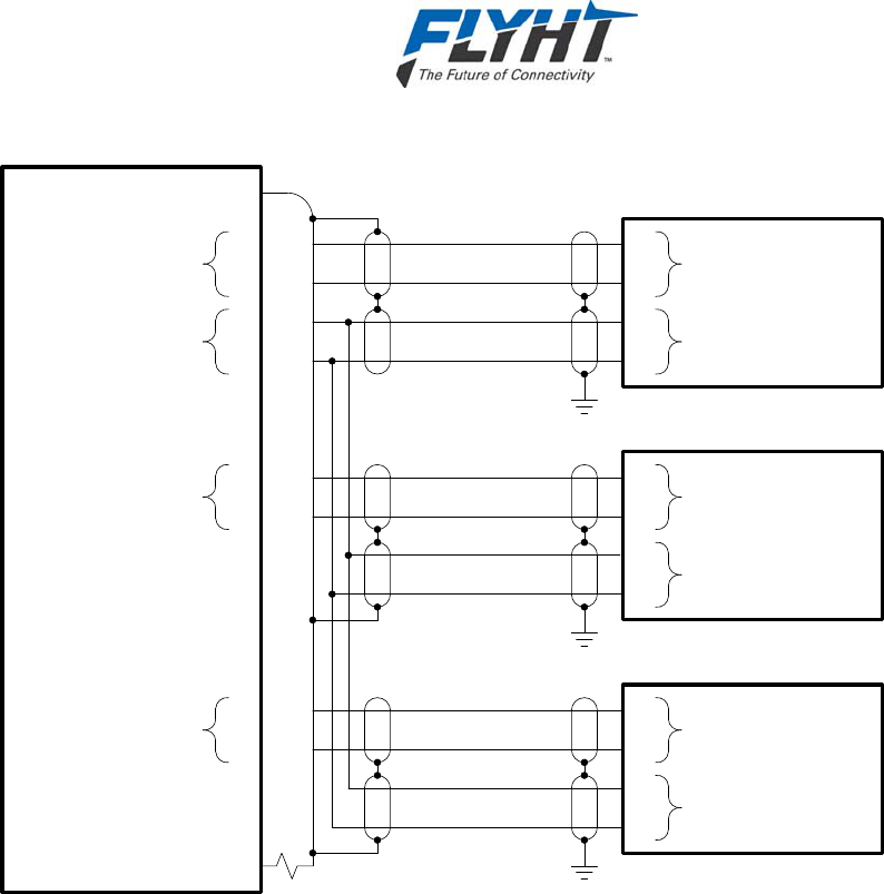
AFIRS 228 Series Installation Manual
Confidential and Proprietary to 250-0019
FLYHT Aerospace Solutions Ltd. Rev. --
Page 40 22 April 2013
DMU
1G
J1B (MP)
1H
A
B
ARINC 429 Rx 1
MCDU 1
1J
1K
A
B
ARINC 429 Tx 1
A
B
A
BARINC 429 Rx
ARINC 429 Tx
3D
A
B
ARINC 429 Rx 2
MCDU 2
A
B
A
BARINC 429 Rx
ARINC 429 Tx
3C
3F
A
B
ARINC 429 Rx 3
MCDU 3
A
B
A
BARINC 429 Rx
ARINC 429 Tx
3E
Figure 7-6 – MCDU Interface
7.8 ICAO Address
The AFIRS 228 uses the aircraft’s ICAO address as the primary method of identifying the
originating aircraft for non-safety services reports it sends to Uptime. It is therefore important
that the correct ICAO address be available from one of the following sources. (The sources are
listed in the order of priority used by the AFIRS 228.)
ACARS CMU 1
ACARS CMU 2
Mode S Transponder 1
Mode S Transponder 2
Owner Requirements Table (ORT) stored in the ACM
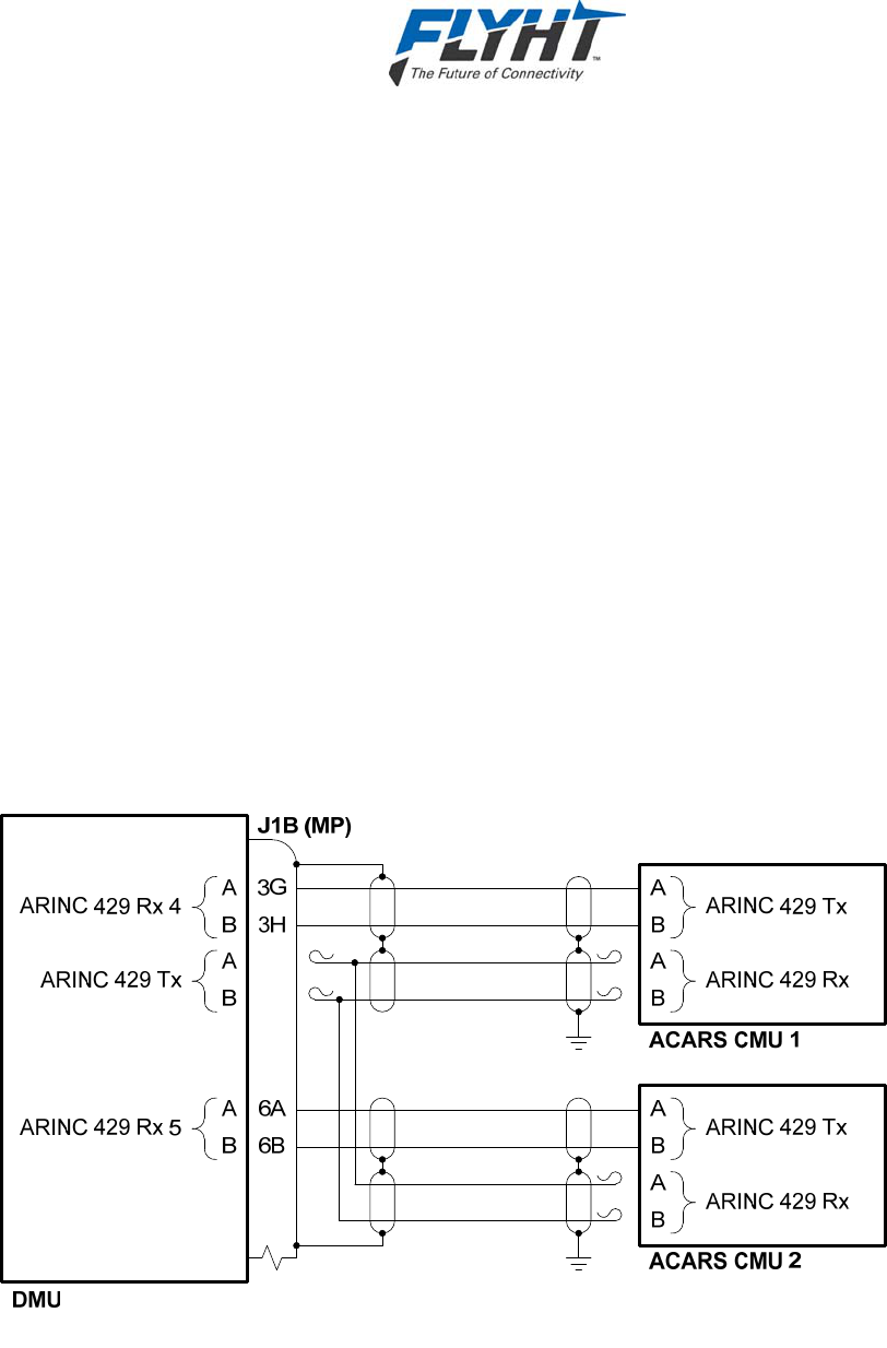
AFIRS 228 Series Installation Manual
250-0019 Confidential and Proprietary to
Rev. -- FLYHT Aerospace Solutions Ltd.
22 April 2013 Page 41
While it is not required for the AFIRS 228 to receive the ICAO address from a CMU or Mode S
Transponder (manually programming the ORT with the correct ICAO address will provide proper
system functionality), using at least one of these interfaces ensures that the AFIRS 228 is using
the same ICAO address that is programmed into the other aircraft systems.
Whenever the AFIRS 228 detects that the ICAO address from the interfaced system is different
than that stored in the ORT and that the new address is valid (i.e. not 000000 or FFFFFF), it will
automatically update the ICAO address stored in the ORT with the new address. If the aircraft’s
registration is ever changed (and the CMU and/or Mode S Transponder addresses are re-
strapped accordingly), no additional maintenance tasks are then required for the AFIRS 228 to
use the new ICAO address.
The system integrator may use none or any combination of the four external system interface
options, depending on the availability of compatible system interfaces and the degree of
redundancy desired.
7.8.1 ACARS CMU
The ACARS ARINC 429 Tx interface will provide safety-services data functionality for the
AFIRS 228S, but it is ‘provisions-only’ for AFIRS 228B. It is recommended that the wires be
capped and stowed near the connectors as shown. ARINC 429 Rx ports 4 and 5 are shown in
Figure 7-7 below, but any Rx port from 2 to 16 may be used.
Figure 7-7 – ACARS Interface
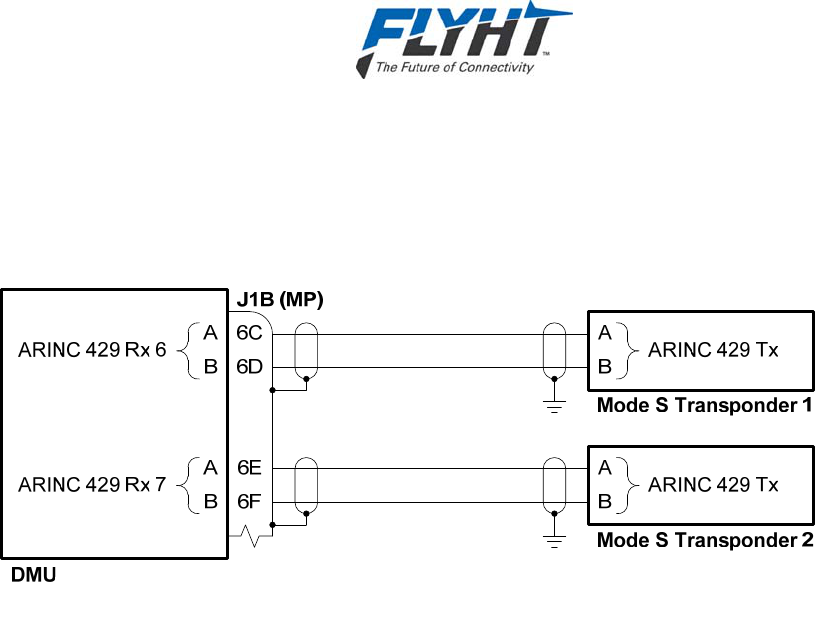
AFIRS 228 Series Installation Manual
Confidential and Proprietary to 250-0019
FLYHT Aerospace Solutions Ltd. Rev. --
Page 42 22 April 2013
7.8.2 Mode S Transponder
ARINC 429 Rx ports 6 and 7 are shown in Figure 7-8 below, but any Rx port from 2 to 16 may
be used.
Figure 7-8 – Mode S Transponder Interface
7.9 Date, Time and Position
The AFIRS 228 uses date, time and position information for numerous purposes, including
information tags attached to various reports and events. Date, time and position information can
be provided by the following sources. (The sources are listed in the order of priority used by the
AFIRS 228.)
External Source 1 (FMS, GPS, etc.)
External Source 2 (FMS, GPS, etc.)
External Source 3 (FMS, GPS, etc.)
Internal GPS
While it is not required for the AFIRS 228 to receive date, time and position information from any
external sources, doing so provides a more robust system design and it is recommended that at
least one external position source be connected if a compatible system interface is available.
The system integrator may use none or any combination of the three external system interface
options, depending on the availability of compatible system interfaces and the degree of
redundancy desired. The ARINC 429 Receiver table in Appendix A identifies the ARINC 429
receiver protocols that AFIRS can use for DTP information.

AFIRS 228 Series Installation Manual
250-0019 Confidential and Proprietary to
Rev. -- FLYHT Aerospace Solutions Ltd.
22 April 2013 Page 43
7.10 Generic ARINC 429 Interfaces
The “Generic 429” protocol allows customizable software components in the AFIRS to access
raw ARINC 429 data from systems whose label definitions are not predefined. Connection and
use of generic ARINC 429 interfaces should only be done in conjunction with FLYHT
engineering support.
The General Purpose Output Bus protocol may be used to provide AFIRS 228 status
information to other aircraft systems (e.g. EICAS, ECAM, CMC, etc.) Presently, none of these
interfaces have been tested by FLYHT, and the system integrator must coordinate with FLYHT
engineering support prior to using this transmitter protocol.
7.11 RS-232/422 Databus
The AFIRS 228 has four serial ports (transmit and receive). Each port is software-configurable
for RS-232 or RS-422 mode. The speed, data bits, parity, stop bits, and flow control settings for
each port are also software-configurable. See Figure 7-9.
Each serial port is assigned 5 pins on the rear connector. The function of these pins is
dependent on whether RS-232 or RS-422 mode is being used.
Table 7-1 – Serial Port Pin Assignments
RS-232 RS-422 Port 1 Port 2 Port 3 Port 4
TXD Tx- 9E 9J 10C 10G
RTS Tx+ 9F 9K 10D 10H
RXD Rx+ 9G 10A 10E 10J
CTS Rx- 9H 10B 10F 10K
Com Not Used 7J 9A 9B 7K
When configured for RS-232 mode, the serial ports support software (Xon/Xoff) and hardware
(RTS/CTS) handshaking. If hardware handshaking is not being used, the RTS and CTS pins do
not need to be connected.
Each of the serial ports can be configured in software for the proper protocol of the external
aircraft system to which it is interfaced. Below is a list of the available protocols. Once a protocol
(except “None” or “Generic”) is selected for any given port, it is no longer available for
assignment to the other ports. Unused serial ports should be configured as “None”.
None
Generic
EFB 1
EFB 2
EFB 3
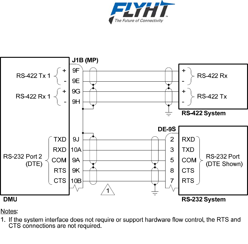
AFIRS 228 Series Installation Manual
Confidential and Proprietary to 250-0019
FLYHT Aerospace Solutions Ltd. Rev. --
Page 44 22 April 2013
Figure 7-9 – Serial Port Interface
7.12 Ethernet
The AFIRS 228 has four Ethernet ports (see Figure 7-10). Each port can auto-negotiate the best
speed (10/100) and mode (full/half duplex). Port 1A is reserved for future use and is currently
not configurable. Ports 2B, 3B, 4B and the Maintenance Port are connected to a second subnet
through an internal managed switch.
The installation design should consider that the IP settings for Port 1A will be different than
those for Ports 2B, 3B, and 4B. Therefore, when identical configuration settings for a group of
devices are desired, they should all be connected to Ports 2B, 3B and 4B. For example, if EFB
1 and EFB 2 were connected to Ports 1A and 2B respectively, they would need to be configured
with different IP settings. If the device locations were exchanged (which would be common for
Class 2 EFBs), neither EFB connections would work until the EFBs were reconfigured. In this
scenario, the preferred design would be to connect the EFBs to Ports 2B and 3B, making their
IP configurations identical. Now if the device locations were swapped, both EFBs connections
would still work without the need to reconfigure the devices.
A 4-conductor Ethernet cable that meets the aircraft’s EWIS requirements must be used. The
rear connector pin layout provides slightly better noise immunity with a star-quad cable
construction, but a twisted-pair cable construction can generally also be used. For star-quad
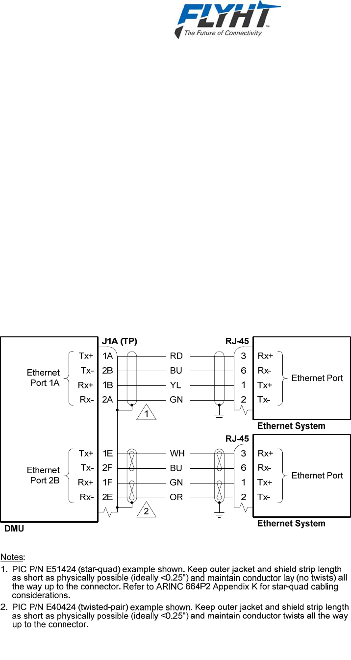
AFIRS 228 Series Installation Manual
250-0019 Confidential and Proprietary to
Rev. -- FLYHT Aerospace Solutions Ltd.
22 April 2013 Page 45
cables, the conductor lay order should be maintained without crossing the conductors when
terminating. For twisted-pair construction, the conductor twists should be maintained right up to
the rear connector. In either case, the best noise immunity is obtained by keeping the strip
length of the shield as short as physically possible, preferably <0.25 inches.
PIC P/N E51424 and ECS P/N 422404 are examples of aircraft-quality star-quad Ethernet
cables that are typically suitable for use. PIC P/N E40424 and ECS P/N 922404 are examples
of aircraft-quality twisted-pair Ethernet cables that are typically suitable for use.
Each of the Ethernet ports can be configured in software for the proper protocol of the external
aircraft system to which it is interfaced. Below is a list of the available protocols.
None
Not Monitored
Monitored
Unused Ethernet ports should be configured as “None”. A “Monitored” port is one where the
AFIRS expects to see an active link and it will generate an error report if the Ethernet link to the
external system is not available. For example, if the AFIRS is connected by Ethernet to a Class
2 EFB that is routinely turned off and stowed for take-off and landing, the port should be
configured as “Not Monitored” or the AFIRS will generate a nuisance fault whenever the EFB is
not powered.
Figure 7-10 – Ethernet Interface

AFIRS 228 Series Installation Manual
Confidential and Proprietary to 250-0019
FLYHT Aerospace Solutions Ltd. Rev. --
Page 46 22 April 2013
7.13 Discrete Inputs
The AFIRS has 14 configurable Discrete Inputs, each of which is software-configurable for
Open-Ground or Open-28V signaling levels, Active High or Active Low logic, and the assigned
function.
7.13.1 Weight-On-Wheels Input
Discrete Input No. 1 (Din 1) is dedicated for use as a Weight on Wheels (WOW1) input. When
there is only one WOW input (i.e. the WOW2 function is not assigned to a Discrete Input; see
§7.13.4) and the ‘WOW1’ input transitions to the active state, the AFIRS is signaled that the
aircraft is on the ground, and the inactive state indicates that the aircraft is in the air.
WOW1 (Din 1) is only an Open-Ground input; it cannot be configured as an Open-28V input. A
Hardware Programming Pin (HPP) is provided to set whether the WOW1 input is Active High or
Active Low. If the WOW HPP pin (J1B-11F) is not connected, WOW1 is configured as an Active
Low input, i.e. Ground = On Ground. If the WOW HPP pin is connected to ground, WOW1 is
configured as an Active High input, i.e. Ground = In Air.
If one of the configurable Discrete Inputs is configured for the WOW2 function (see §7.13.4), the
following logic is used to determine the aircraft’s Air-Ground status:
When the ‘WOW1’ discrete input is in the active state (as configured by the WOW HPP
strapping) and the ‘WOW2’ discrete input is in the active state (as defined by the ICT setting
for the discrete input configured as ‘WOW 2’), the aircraft is considered as ‘Weight On
Wheels’.
When any of the WOW discrete inputs are in the inactive state, the aircraft is considered as
‘Weight Off Wheels’.
7.13.2 Signal Level Configuration
Each configurable Discrete Input is software-configurable for ‘Open-Ground’ or ‘Open-28V’
signaling levels.
When configured as ‘Open-Ground’, the input is pulled-up to 28V internally (High State) and
applying a ground input (<3.5 V) transitions the input to the Low State.
When configured as ‘Open-28V’, the input is pulled-down to 0V internally (Low State) and
applying a voltage signal to the input (>7.0 V) transitions the input to the High State.
7.13.3 Logic Configuration
Each configurable Discrete Input is software-configurable for ‘Active Low’ or ‘Active High’
signaling levels. See Table 7-2.
When configured as ‘Active Low’, the function is considered to be active when the input is in the
Low State (<3.5V).
When configured as ‘Active High’, the function is considered to be active when the input is in the
High State (>7.0V).

AFIRS 228 Series Installation Manual
250-0019 Confidential and Proprietary to
Rev. -- FLYHT Aerospace Solutions Ltd.
22 April 2013 Page 47
Table 7-2 – Discrete Input Configurable States
Electrical
Characteristic Logic
Assignment Description
Negative-Seeking
(Open-Ground)
Pulled Up to 28 V
Active Low The input function is considered to be in its active state
when the input is in the ‘Logic Low’ voltage range (<3.5 V).
Active High The input function is considered to be in its active state
when the input is in the ‘Logic High’ voltage range (>7.0 V).
Positive -Seeking
(Open-28 V)
Pulled Down to 0 V
Active High The input function is considered to be in its active state
when the input is in the ‘Logic High’ voltage range (>7.0 V).
Active Low The input function is considered to be in its active state
when the input is in the ‘Logic Low’ voltage range (<3.5 V).
7.13.4 Function Assignment
Each configurable Discrete Input can be configured in software to assign the input’s function.
Once a function (except “None” and “Generic Discrete”) is selected for any given input, it is no
longer available for assignment to any of the other inputs. See Figure 7-11.
The ‘Mic On’, ‘End Call’, and ‘Chime Reset’ functions are used in conjunction with the Extension
1 audio interface and are discussed in §7.15.1.1 below.
Discrete Input No. 1 (Din 1) is dedicated as a Weight on Wheels (WOW1) input. Only Discrete
Inputs Din 2 through Din 15 are software-configurable.
None
When an input is not connected to an active system (e.g. no connection, or wiring provisions
only are installed), the input should be configured as “None”.
Generic Discrete
The “Generic Discrete” function allows customizable software components in the AFIRS to
access raw discrete input data from systems whose input functions are not predefined.
Connection and use of generic discrete input interfaces should only be done in conjunction with
FLYHT engineering support.
Cabin Lock
When ‘Cabin Lock’ is selected, cabin voice extensions are prevented from initiating a voice call,
and if any voice call is in progress on a cabin extension, it is terminated. This input is only
needed if there are cabin extensions being installed (Extensions 2 and/or 3) and the system
integrator wants to provide the flight crew with the means to disable them.
The ‘Cabin Lock’ discrete will toggle the cabin lock function between the inactive and active
states only when the discrete input transitions from the inactive state to the active state, e.g. this
would be accomplished by a momentary switch used to turn the ‘Cabin Lock’ function on and off
on subsequent button presses. At system power up in this mode, the input resets to the inactive
state (Cabin Active).

AFIRS 228 Series Installation Manual
Confidential and Proprietary to 250-0019
FLYHT Aerospace Solutions Ltd. Rev. --
Page 48 22 April 2013
Note:
Cabin Lock functionality is also provided on the MCDU interface. A Cabin Lock discrete input is
only required if the system integrator wants to provide Cabin Lock functionality and there is no
MCDU, or if the system integrator wants to use a discrete input instead of the MCDU interface.
Event
When the ‘Event’ input transitions to the active state (momentary switch), it provides an
indication to the AFIRS system that a noteworthy event has been identified by the flight crew.
The AFIRS system can use the ‘Event’ input to perform custom pre-defined functions, so its use
needs to be coordinated with FLYHT engineering support.
Iridium Off
The functionality of this discrete input can be configured by the operator to be either ‘All Off’ or
‘Data Off’. When configured for ‘All Off’ and the ‘Iridium Off’ input goes active, all voice and data
transmissions over the Iridium modems are inhibited (all Iridium voice and data services are
turned off and the AFIRS does not emit any RF energy). When configured for ‘Data Off’ and the
‘Iridium Off’ input goes active, only data transmissions over the Iridium modems are inhibited
(Iridium voice services and data receipt functions remain operational). When ‘Iridium Off’ is
deselected, normal Iridium functions will occur.
The Iridium Off discrete will toggle the ‘Iridium Off’ function between the inactive and active
states only when the discrete input transitions from the inactive state to the active state, e.g. this
would be accomplished by a momentary switch used to turn the ‘Iridium Off’ function on and off
on subsequent button presses. At system power up in this mode, the input resets to the inactive
state (Iridium On).
Note:
Iridium Off functionality is also provided on the MCDU interface. Iridium Off discrete input is only
required if the system integrator wants to provide Iridium Off functionality and there is no MCDU,
or if the system integrator wants to use a discrete input instead of the MCDU interface.
Park Brake
A ‘Park Brake’ input should be provided to the AFIRS whenever possible, either from one of the
digital databuses or using a discrete input. For the discrete input, when the ‘Park Brake’ input
transitions to the active state, the AFIRS is signaled that the aircraft’s park brake is set, and the
inactive state indicates that the aircraft’s park brake is released (not set).
System Reset
When the ‘System Reset’ input transitions to the active state (momentary switch), it commands
the system to perform a reset. This function is not commonly used in aircraft installations, but it
is available if needed.
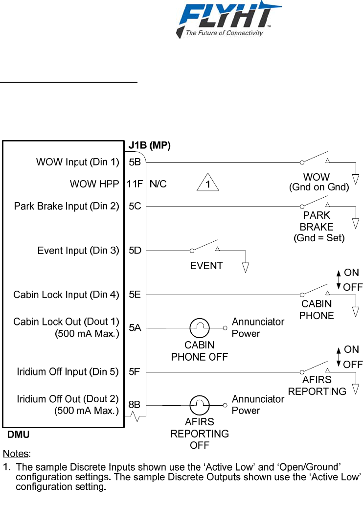
AFIRS 228 Series Installation Manual
250-0019 Confidential and Proprietary to
Rev. -- FLYHT Aerospace Solutions Ltd.
22 April 2013 Page 49
Weight on Wheels (WOW2)
A second Weight-On-Wheels input may optionally be provided to the AFIRS system. Refer to
§7.13.1 for the logic used when a ‘WOW2’ input is provided.
Figure 7-11 – Discrete Input and Output Interfaces
7.14 Discrete Outputs
The AFIRS has 8 configurable Discrete Outputs, each of which is software-configurable for
Active High or Active Low logic and the assigned function. The Discrete Outputs use ‘Open-
Closed’ signal levels, where the output is either high-impedance to ground (Open) or low-
impedance to ground (Closed).
Once a function (except “None”) is selected for any given output, it is no longer available for
assignment to any of the other outputs.

AFIRS 228 Series Installation Manual
Confidential and Proprietary to 250-0019
FLYHT Aerospace Solutions Ltd. Rev. --
Page 50 22 April 2013
7.14.1 Logic Configuration
Each Discrete Output is software-configurable for ‘Active Low’ or ‘Active High’ signaling levels.
When configured as ‘Active Low’ and the assigned function goes active, the output will be in the
Low State (<1.25V to ground). When the assigned function goes inactive, the output will be in
the High State (Open Circuit).
When configured as ‘Active High’ and the assigned function goes active, the output will be in the
High State (Open Circuit). When the assigned function goes inactive, the output will be in the
Low State (<1.25V to ground).
7.14.2 Function Assignment
Each Discrete Output can be configured in software to assign the output’s function. Once a
function (except “None”) is selected for any given output, it is no longer available for assignment
to any of the other outputs.
The ‘Call Light’ function is used in conjunction with the Extension 1 audio interface and is
discussed in §7.15.1.1 below. The ‘Ext 2 Call’ and ‘Ext 3 Call’ functions are used in conjunction
with the Extension 2 and 3 audio interfaces and are discussed in §7.15.3 below.
None
When an output is not connected to an active system (e.g. no connection, or wiring provisions
only are installed), the output should be configured as “None”.
Cabin Lock
The ‘Cabin Lock’ output reports the state of the ‘Cabin Lock’ function. This output can be used
to illuminate an annunciator when the ‘Cabin Lock’ function is active.
GPS Link
The ‘GPS Link’ output reports the loss of valid data from all of the system’s Date-Time-Position
(DTP) sources. This includes the external DTP sources (e.g. FMSs) as well as the internal GPS
satellite link. This output can be used to illuminate an annunciator whenever there are no DTP
sources available. Note that this output may be active whenever the AFIRS antenna does not
have a clear view of the sky and the external DTP sources are not able to provide valid DTP
information (e.g. the aircraft is in a hangar).
Iridium Off
The ‘Iridium Off’ output reports the state of the ‘Iridium Off’ function. This output can be used to
illuminate an annunciator when the ‘Iridium Off’ function is active.
ISVM Link
The ‘ISVM Link’ output reports the status of the internal Iridium voice modem satellite link. This
output can be used to illuminate an annunciator whenever the ISVM cannot receive satellite
signals. Note that this output will be active whenever the AFIRS antenna does not have a clear
view of the sky (e.g. the aircraft is in a hangar).

AFIRS 228 Series Installation Manual
250-0019 Confidential and Proprietary to
Rev. -- FLYHT Aerospace Solutions Ltd.
22 April 2013 Page 51
ISDM Link
The ‘ISDM Link’ applies only to the AFIRS 228S. This output reports the status of the internal
Iridium safety-service data satellite link. This output can be used to illuminate an annunciator
whenever the ISDM cannot receive satellite signals. Note that this output will be active
whenever the AFIRS antenna does not have a clear view of the sky (e.g. the aircraft is in a
hangar).
Text Msg
The ‘Text Msg’ output indicates that the AFIRS text messaging service has received a new
message. This output can be used to illuminate an annunciator when a new text message is
received.
7.15 Satcom
This section describes the interface and integration requirements for the AFIRS 228 Series
system with a Satcom system.
7.15.1 Audio Integrating System
Extension 1 is generally intended to be connected to the aircraft’s audio integrating system for
flight crew use. The interfaces required to fully support this functionality vary significantly
depending on the design of the audio integrating system. Generally, the MCDUs are used for
control and display of the Satcom functions for Extension 1.
7.15.1.1 Audio Discrete Signals
There are 3 discrete inputs and 2 discrete outputs that can be used to support the integrated
audio interface.
Mic On Input
The ‘Mic On’ function can be configured for either ‘Switched PTT’ (momentary switch) or
‘Latched ACP’ (alternate action switch) mode.
When the ‘Mic On’ input is configured for ‘Switched PTT’, Voice Extension 1 (Mic/Phone input)
will answer an incoming call when the ‘Mic On’ input transitions to the active state. Once a call is
in progress, the microphone audio channel will function as long as the ‘Mic On’ input is in the
active state. If a call is in progress and the ‘Mic On’ input toggles to the inactive state, the
microphone audio input will be muted. In this mode, the ‘Mic On’ input does not terminate a call
in progress.
When the ‘Mic On’ input is configured for ‘Latched ACP’, Voice Extension 1 (Mic/Phone input)
will answer an incoming call when the ‘Mic On’ input transitions to the active state. Once a call is
in progress, the microphone audio channel will function as long as the ‘Mic On’ input is in the
active state. If a call is in progress and the ‘Mic On’ input toggles to the inactive state, the call
will be terminated.

AFIRS 228 Series Installation Manual
Confidential and Proprietary to 250-0019
FLYHT Aerospace Solutions Ltd. Rev. --
Page 52 22 April 2013
For outgoing calls when the ‘Mic On’ input is configured for ‘Latched ACP’, the function is
dependent on which control source is configured for Extension 1. When an MCDU is the
Extension 1 dialing control, setting the ‘Mic On’ input to the active state will initiate the dialing
process using the phone number preselected on the MCDU. When a DTMF Dial Pad is the
Extension 1 dialing control, setting the ‘Mic On’ input to the active state indicates an off-hook
event so that DTMF dialing can begin.
End Call Input
When a call is in progress and the ‘End Call’ input transitions to the active state (momentary
switch), Voice Extension 1 (Mic/Phone input) will terminate the call in progress. This input is
often used to terminate a call when the ‘Mic On’ input is configured for ‘Switched PTT’ mode.
Additionally, the ‘End Call’ input can be used to reject an incoming call, regardless of whether
the ‘Mic On’ input is configured for ‘Switched PTT’ or ‘Latched ACP’.
Call Light Output
The ‘Call Light’ output is software configurable for either steady or flashing lights. When an
incoming voice call is ringing, the ‘Call Light’ output will transition to the active state; either in a
steady state or flashing at approximately a 1 Hz rate. When the incoming call is subsequently
answered, the ‘Call Light’ output will remain active in the steady state as long as the call is in
progress. When the call in progress is terminated, the ‘Call Light’ output will go inactive.
Chime Output
The ‘Chime’ output is software configurable for either single-stroke or multi-stroke. When an
incoming voice call starts ringing, the ‘Chime’ output will transition to the active state and then
the inactive state; either once (single-stroke) or on and off until the call is answered or the
‘Chime Reset’ input goes active (multi-stroke).
The time that the ‘Chime’ output is active and inactive is configurable in the ICT. The default
settings of 500 ms on and 500 ms off provide an ARINC 741/761 compliant output. However, if
a chime device such as a Sonalert is being used, the default times are too short. A chime active
setting of 2.5 to 3.0 seconds and a corresponding inactive setting that produces the desired
repetition rate may be more suitable, depending on the characteristics of the actual device being
used.
Chime Reset Input
When an Iridium voice call is ringing and the ‘Chime Reset’ input transitions to the active state
(momentary switch), the ‘Chime’ output will be reset (i.e. transition to the inactive state) for the
remainder of the time that the incoming call is ringing. This input is typically only required if the
‘Chime’ output is used and it is configured for multi-stroke chime.
Note:
When ‘Chime Reset’ is applied, the chime is silenced but the function of the Call Light output is
unaffected.
7.15.1.2 Switched PTT Configuration
If the Audio Integrating System provides a momentary Push-To-Talk (PTT) output, the following
interface can be used. When an incoming call is ringing and the PTT is keyed, the call will be
answered. Once the call is established, the PTT must be keyed for the microphone audio to be
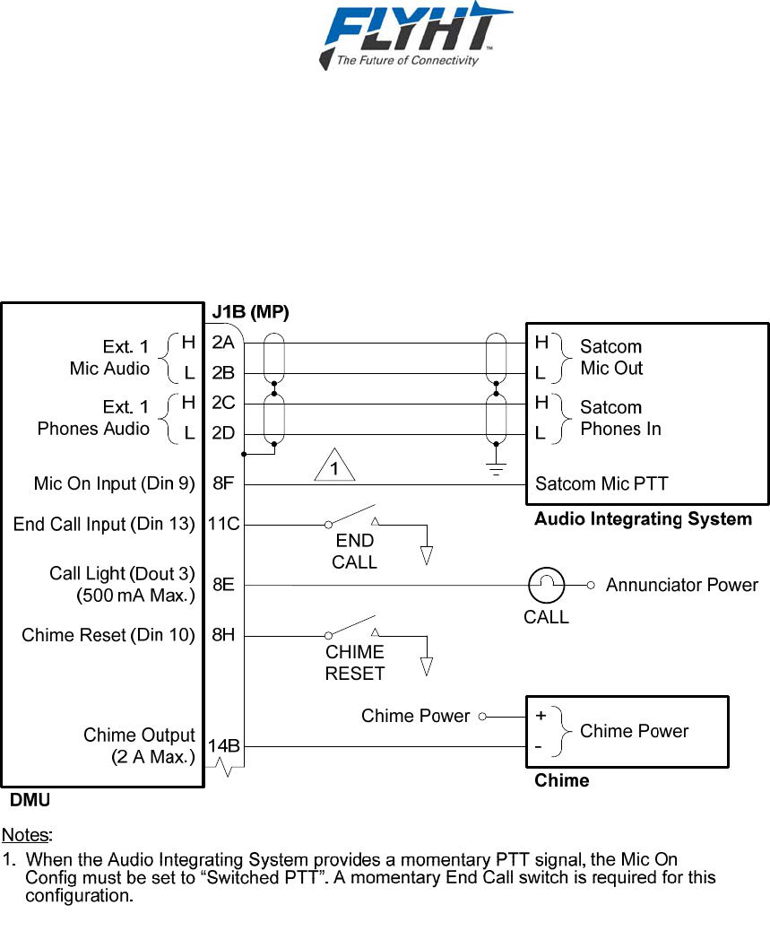
AFIRS 228 Series Installation Manual
250-0019 Confidential and Proprietary to
Rev. -- FLYHT Aerospace Solutions Ltd.
22 April 2013 Page 53
transmitted. The End Call switch is used to end the call. Calls can also be answered and
terminated on the MCDU screen, if available.
The Call Light, Chime and Chime Reset interfaces can be used to provide visual and aural
annunciations in the cockpit. The system integrator should design the visual and aural call
indications to be consistent with the aircraft’s cockpit design philosophy. See Figure 7-12.
Figure 7-12 – Switched PTT Audio Interface
7.15.1.3 Latched ACP Configuration
If the Audio Integrating System provides a latched Mic On output, the following interface can be
used. When an incoming call is ringing and the Satcom switch on the Audio Control Panel is
pressed, the call will be answered and microphone audio will always be live. The Satcom switch
on the Audio Control Panel is pressed a second time to end the call. Calls cannot be answered
and terminated on the MCDU screen in this configuration.
The following diagram also shows how the Call Light output can be interfaced to an Audio
Integrating System that provides Satcom visual and aural call indications. In this case, a Call
Light, Chime and Chime Reset switch are not required. See Figure 7-13.
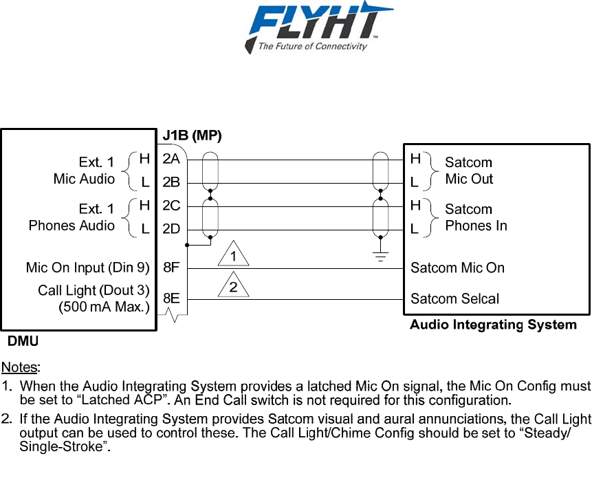
AFIRS 228 Series Installation Manual
Confidential and Proprietary to 250-0019
FLYHT Aerospace Solutions Ltd. Rev. --
Page 54 22 April 2013
Figure 7-13 – Latched ACP Audio Interface
7.15.2 DTMF Dialing Source
If a compatible MCDU is not available in the aircraft, a 2-wire dial pad may be used to provide
control and display of the Satcom functions for Extension 1. The following figure shows a typical
dial pad installation. Refer to the applicable dial pad manufacturer’s installation instructions for
proper wiring connections.
The Call Light, Chime and Chime Reset interfaces are optional, and can be used to provide
visual and aural annunciations in the cockpit. The system integrator should design the visual
and aural call indications to be consistent with the aircraft’s cockpit design philosophy. See
Figure 7-14.
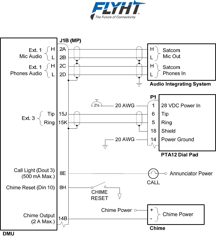
AFIRS 228 Series Installation Manual
250-0019 Confidential and Proprietary to
Rev. -- FLYHT Aerospace Solutions Ltd.
22 April 2013 Page 55
Figure 7-14 – Dial Pad Interface
7.15.3 Satcom Handsets
The AFIRS 228 can connect with up to two handsets. Any aviation-quality handset with a 2-wire
POTS interface (meeting the specifications of §4.1.10) may be used.
The handsets are generally intended for cabin crew use. A handset is not recommended for use
in the cockpit, as the integrated audio interface is preferred. The following diagram shows a
typical cordless base station interfaced to Extension 2 and a regular handset to Extension 3, but
either handset type may be used at either extension. Refer to the applicable handset
manufacturer’s installation instructions for proper wiring connections.
If Extension 3 is used as a DTMF dialing source for the Extension 1 audio interface, then only
Extension 2 is available for connection to a handset.
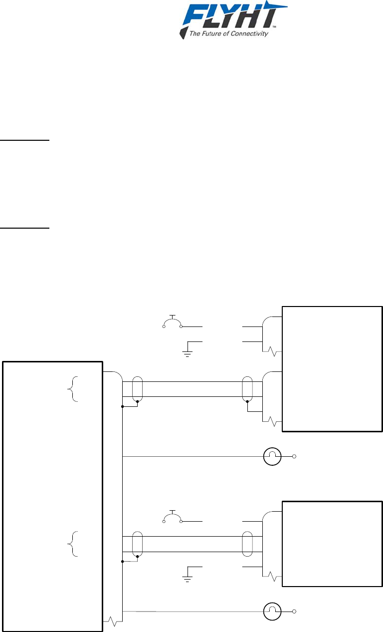
AFIRS 228 Series Installation Manual
Confidential and Proprietary to 250-0019
FLYHT Aerospace Solutions Ltd. Rev. --
Page 56 22 April 2013
Call Lights for Extensions 2 and 3 may be located near the respective handset to provide an
additional visual indication that the extension is ringing. Their use is optional and at the system
integrator’s discretion. Discrete outputs 4 and 5 are shown, but any of the configurable discrete
outputs may be used. See Figure 7-15.
Ext 2 Call
The ‘Ext 2 Call’ output can be configured for either steady or flashing lights. When a voice call
on Extension 2 is ringing, the ‘Ext 2 Call’ output will transition to the active state; either in a
steady state or flashing at a 1 Hz rate. When the incoming call is subsequently answered, the
‘Ext 2 Call’ output will remain active in the steady state as long as the call is in progress on
Extension 2. When the call in progress is terminated, the ‘Ext 2 Call’ output will go inactive.
Ext 3 Call
The ‘Ext 3 Call’ output can be configured for either steady or flashing lights. When a voice call
on Extension 3 is ringing, the ‘Ext 3 Call’ output will transition to the active state; either in a
steady state or flashing at a 1 Hz rate. When the incoming call is subsequently answered, the
‘Ext 3 Call’ output will remain active in the steady state as long as the call is in progress on
Extension 3. When the call in progress is terminated, the ‘Ext 3 Call’ output will go inactive.
Cordless Base Station
Tip
Ring
DMU
15G
J1B (MP)
15H
Tip
Ring
Ext. 2
15J
15K
Tip
Ring
Ext. 3
1
2
3
Jetphone Handset
28 VDC Power In
Tip
Ring
1
9
7
3
28 VDC Power In
Power Ground
2
1
P2
P1
Shield
Power Ground
2½ 20 AWG
20 AWG
2½ 20 AWG
20 AWG
CALL
(Opt.)
8G
Ext 2 Call (Dout 4)
(500 mA Max.)
11G
Ext 3 Call (Dout 5)
(500 mA Max.)
CALL
(Opt.)
Annunciator Power
Annunciator Power
P1
Figure 7-15 – Handset Interface
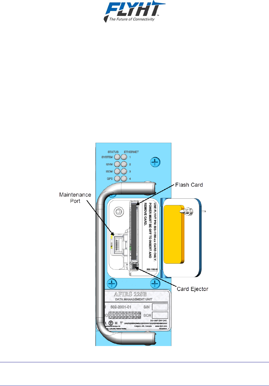
AFIRS 228 Series Installation Manual
250-0019 Confidential and Proprietary to
Rev. -- FLYHT Aerospace Solutions Ltd.
22 April 2013 Page 57
8. SYSTEM CONFIGURATION
You configure the AFIRS system via the Maintenance Port using a laptop, web browser, and the
AFIRS 228 Series maintenance program which has a graphical user interface (GUI).
IMPORTANT: This manual provides information on how to connect to the Maintenance Port and
access the AFIRS maintenance program. It also provides general information on the steps
required to configure and update the AFIRS system. Detailed information on how to operate the
maintenance program and troubleshoot the operation of the AFIRS system is provided in the
AFIRS 228 Series, Automated Flight Information Reporting System’s Operator’s Manual,
document number 250-0022.
The AFIRS 228 Series has an Ethernet interface for the Maintenance Port connection. An RJ-45
Maintenance Port jack is located behind the access door on the front panel of the DMU as
shown in Figure 8-1.
Figure 8-1 – Maintenance Port Location
Note:
When performing the initial configuration of an installed system, perform and complete the
Before Power-On Tests in section 9.1 before applying power to the AFIRS system.
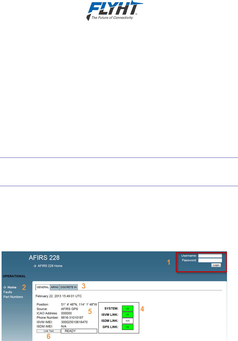
AFIRS 228 Series Installation Manual
Confidential and Proprietary to 250-0019
FLYHT Aerospace Solutions Ltd. Rev. --
Page 58 22 April 2013
8.1 Connecting to the Maintenance Port
You access the AFIRS 228 Maintenance Program by connecting an Ethernet cable to the
Maintenance Port of the AFIRS 228 unit. Alternatively, as described in section 7.12, one of the
rear connector Ethernet ports can be used to provide an additional Maintenance Port
connection in the aircraft (e.g. in the cockpit) so that system maintenance activities can be
performed in a location remote from the AFIRS 228 Data Management Unit (DMU).
Also, if an Electronic Flight Bag (EFB) with a supported web browser installed is connected to
one of the rear Ethernet port connections, the EFB can be used as an AFIRS maintenance
terminal and a laptop is not required.
To connect to the Maintenance Port and access the Maintenance Program:
1. On the AFIRS 228 unit, open the front panel access door.
2. Connect an Ethernet cable to the Maintenance Port. AFIRS 228 system power may be on or
off.
3. Connect the other end of the Ethernet cable to a laptop that is running a web browser.
Note:
The laptop network adapter must be set to DHCP to access the IP address. FLYHT has
tested Internet Explorer 8, Firefox 7 and 9, and Google Chrome 16 (or later versions) with
the AFIRS 228.
4. If not already powered, apply power to the AFIRS DMU.
5. Confirm that the green link light (adjacent to Maintenance Port RJ45 connector) is
illuminated, either steady or flashing (a flashing link light indicates that data is being
transmitted).
6. Open a web browser on the laptop and in the Address bar type the following IP address:
192.168.128.1
The AFIRS 228 Home page appears with the General tab information displayed.
Figure 8-2 – Home Page – General Tab

AFIRS 228 Series Installation Manual
250-0019 Confidential and Proprietary to
Rev. -- FLYHT Aerospace Solutions Ltd.
22 April 2013 Page 59
The Home page (see Figure 8-2) displays three main areas of information:
1 Login area
2 Menu of available links to pages accessible in current login mode of operation
3 Status tabs: General, ARINC, and Discrete In
Upon login, the default view opens to the General tab (see Figure 8-2) which displays the
following information:
4 System status data display area
5 System information data display area
6 Link test (user activated) used to test the connection to the Uptime Server
For information on the other two Home page tabs (ARINC and Discrete In) see section
8.1.1.
8.1.1 Home Page Tab Descriptions
The General tab page displays:
UTC Date and Time: This is correlated to a GPS clock if you have a fixed GPS link. If no
link is available a default date will be displayed.
Position: This is the AFIRS GPS position. If no GPS is fixed, No GPS will be displayed.
ICAO Address: This field displays the aircrafts ICAO address. The address is configured at
system setup by the installer (must be in Maintenance Installer mode).
Phone Number: Displays the aircraft phone number.
ISVM IMEI: Iridium Satellite Voice Modem International Mobile Equipment Identity.
ISDM IMEI: Iridium Satellite Data Modem: Not available in this release.
Link Test: This is an active selection which is used to verify a link between a registered
AFIRS 228 unit and the FLYHT Uptime Server. When Link Test is selected a packet of
information transmitted to the FLYHT Uptime Server. If the information is received the
Uptime Server will reply with an acknowledgement. Successful communication is confirmed
by a RECEIVED message, unsuccessful communication is confirmed by a TIME OUT
message.
AFIRS 228 Status Indicators:
System: Yellow (INIT) initializing, Green (OK), Yellow (FAULT), Red indicates Aircraft
Configuration Module (ACM) or Data Management Unit (DMU) Hardware failure - critical
ISVM LINK: Yellow (NO FIX) no iridium link, Green (OK)
ISDM LINK: N/A, future functionality
GPS LINK: Yellow (NO FIX), Green (OK)
The ARINC tab displays the state of the 16 ARINC 429 RX channels and the 1 ARINC 717 RX
channel. The status of a configured function is either ACTIVE or FAULT.
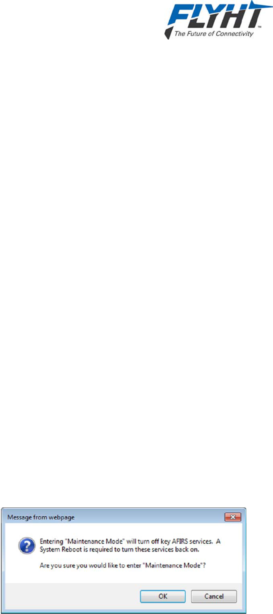
AFIRS 228 Series Installation Manual
Confidential and Proprietary to 250-0019
FLYHT Aerospace Solutions Ltd. Rev. --
Page 60 22 April 2013
The DISCRETE IN tab displays the state of the 16 discrete inputs. The state of the configured
functional input is either ACTIVE or INACTIVE.
8.1.2 Faults Page
The Faults page provides access to the AFIRS system fault log and history.
8.1.3 Part Numbers Page
The Part Numbers page provides the status of the software and hardware configuration of the
AFIRS system.
8.2 Accessing Maintenance Mode
To make changes to the configuration tables, you need to access the Maintenance Mode
function of the AFIRS maintenance program.
Current versions of the maintenance program do not require a user name and password for
access to Maintenance Mode. This functionality may be available in later versions of the
software.
Before accessing Maintenance Mode, you need to be connected to the AFIRS Maintenance
Port and have the Maintenance Program open.
To access and login to Maintenance Mode:
1. Once connected to the AFIRS 228 Maintenance Port and Maintenance Program GUI, from
the Home page, click Login. You do not need a Username and Password.
The AFIRS 228 Home page appears and the status fields will reflect your current system
health. The AFIRS 228 Home page now indicates that you are logged in as an Installer,
which provides you with the capability to enter Maintenance Mode.
2. To enter Maintenance Mode, on the top right corner of the screen, click Enter Maintenance
Mode.
A confirmation prompt message appears (see Figure 8-3) reminding you that if you enter
Maintenance Mode key AFIRS services will be turned off. You will need to reboot the system
(full system reset) to turn the services back on and return to normal Operational Mode.
Figure 8-3 – Entering Maintenance Mode Message
3. To enter Maintenance Mode, select OK.
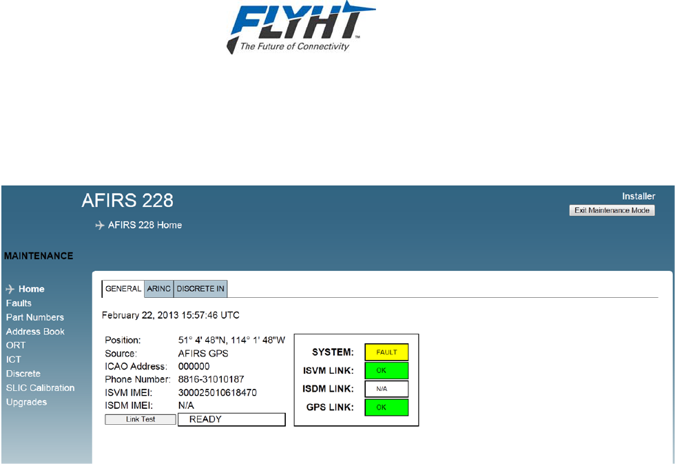
AFIRS 228 Series Installation Manual
250-0019 Confidential and Proprietary to
Rev. -- FLYHT Aerospace Solutions Ltd.
22 April 2013 Page 61
The Home screen appears as shown in Figure 8-4. The SYSTEM status indicates that the
system is “in fault” and appears illuminated in yellow. This SYSTEM fault status is indicated
as the AFIRS system turns off when you are in Maintenance Mode. When you exit
Maintenance Mode, and the system restarts, the SYSTEM status will appear green.
Figure 8-4 – Maintenance Mode Initial Display Screen
In Maintenance Mode, the Home page provides the following additional left-hand menu items:
Address Book, ORT, ICT, Discrete, SLIC Calibration, and Upgrades.
The following sections describe the functionality of the additional menu items available in
Maintenance Mode.
Detailed information on how to use the Maintenance Mode program are provided in the AFIRS
228 Series Operator’s Manual, document number 250-0022.
8.2.1 Maintenance Mode Menu Descriptions
The links available from the left-hand menu enable the Maintenance Installer to check, test,
verify, and configure the AFIRS system as follows:
Click Address Book to add, delete, or edit contact information, set call priorities and
extension dialing, and enable/disable protection.
Click ORT (Owner Requirements Table) to configure customized settings for specific
aircraft and or operator requirements. Refer to the Appendix for a worksheet to help you
define your requirements before editing the ORT information.
Click ICT (Installation Configuration Table) to define how the AFIRS system interfaces to
the aircraft. Refer to the Appendix for a worksheet to help you define your system
requirements before editing the ICT information.
Click Discrete to display the configuration of the Discrete Outs for testing purposes. You
can verify the function of systems interfaced to the various discrete outputs by toggling
the state from ACTIVE to INACTIVE and verify the expected response.

AFIRS 228 Series Installation Manual
Confidential and Proprietary to 250-0019
FLYHT Aerospace Solutions Ltd. Rev. --
Page 62 22 April 2013
Click SLIC Calibration to calibrate the interface for phone extensions 2 and 3. You need
to calibrate the SLIC interface at time of installation and system configuration to improve
noise immunity on the twisted pairs connected to additional handsets (if they are
installed and operational).
Click Upgrades to upgrade and update the software of the AFIRS 228 system.
8.3 Configuring the AFIRS 228 System
This section provides basic information on how to configure the AFIRS 228 system as a
Maintenance Installer logged into the Maintenance Mode of the AFIRS maintenance program.
Detailed information about how to operate and use the maintenance program accessed via the
AFIRS 228 maintenance port is provided in the AFIRS 228 Operator’s Manual (document
number 250-0022) which is available from FLYHT’s product support department.
The following sections are intended to provide you with information on the configuration process
and data inputs required to install and verify a system as operational. Worksheets for the ORT
and ICT data are provided in the Appendix of this manual and the AFIRS 228 Series Operator’s
Manual.
Aircraft specific information required to configure the system should be provided to the installer
by the aircraft specific documentation and the Instructions for Continued Air-Worthiness.
For the purposes of installation, system configuration and verification, the following steps should
be completed:
1. Configure the Address Book and set call priorities.
2. Configure the ORT data.
3. Define the ICT for aircraft and system interface requirements.
4. Calibrate SLIC for extensions 2 and 3 (if installed).
8.3.1 Configuring the Address Book
The Address Book can only be edited if you are logged into Maintenance Mode. If you are in
Operational Mode, you can view the Address Book content, but not edit the information or
change the settings. The address book entries can also be viewed by a MCDU; however, you
can only edit the information or change settings from within the AFIRs Maintenance Program.
To access the Address Book:
1. From the left-hand menu, click Address Book. The Address Book screen appears (see
Figure 8-5).
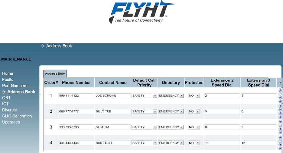
AFIRS 228 Series Installation Manual
250-0019 Confidential and Proprietary to
Rev. -- FLYHT Aerospace Solutions Ltd.
22 April 2013 Page 63
Figure 8-5 – Address Book Screen
2. Add contact information or edit information as required after reviewing the configuration tips
provided below.
Important tips for configuring the Address Book:
Order#: If you are not using an MCDU, but are using a dialer pad, you can use the Order
# for speed dialing of the address entries.
Phone Number: Enter the phone number for each contact.
Contact Name: Use uppercase letters in the Contact Name text field. Lower case
letters will not be accepted by the system as a valid entry.
Default Call Priority: You can set the Default Call Priority to match the terminology of
either Airbus or Boeing categories. Airbus options are Emergency, Safety, Non-Safety,
and Public. Boeing options are Emergency, Operational High, Operational Low, and
Public.
Protected: Under Protected if you select YES, you “protect” the Address Book entry so
that it cannot be edited from the MCDU. If you select NO, the Address Book entry will be
“unprotected” and therefore editable from the MCDU.
Extension 2 and 3 Speed Dial: Used to configure speed dialing to extensions on the
aircraft. When using a MCDU, you will have access to Extension 2 and 3. When using an
AFIRS Keypad, you will only have access to one extension: Extension 2.
8.3.2 Configuring the Owner Requirements Table
The Owner Requirements Table (ORT), shown in Figure 8-6 contains the configuration items
that may be customized by the individual aircraft operator. These settings may be changed as
required to meet operational requirements or preferences.
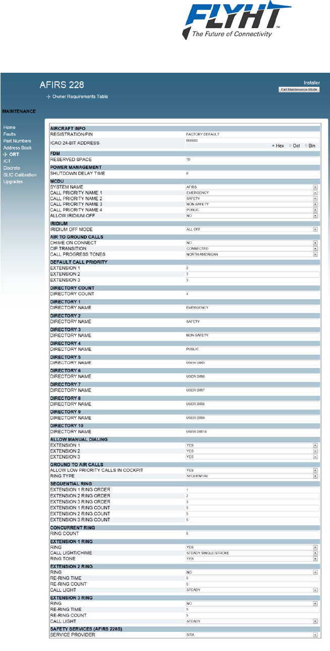
AFIRS 228 Series Installation Manual
Confidential and Proprietary to 250-0019
FLYHT Aerospace Solutions Ltd. Rev. --
Page 64 22 April 2013
Figure 8-6 – ORT Screen

AFIRS 228 Series Installation Manual
250-0019 Confidential and Proprietary to
Rev. -- FLYHT Aerospace Solutions Ltd.
22 April 2013 Page 65
Note:
An ORT Configuration Worksheet is provided in Appendix B to assist the operator in selecting
and documenting the correct ORT configuration settings.
To access and edit the ORT:
1. Click the ORT link on the left-hand side of the screen. The ORT page appears.
2. Enter the AIRCRAFT INFO: REGISTRATION or FLEET IDENTIFICATION NUMBER (FIN).
The content of this field is typically used in AFIRS reports that are sent off the aircraft. This
entry is a “free text” field that can be up to 24 characters long. The character set for this field
is limited to those characters that can be entered and displayed on an MCDU, which are the
uppercase alpha-numeric characters plus five special characters: [Space] + - . /
3. Enter the aircraft’s 24-bit ICAO address.
The content of this field is typically used in AFIRS reports that are sent off the aircraft. The
address can be entered and displayed in hexadecimal, octal, or binary format.
Note:
If the aircraft installation includes an interface to a system that provides the ICAO address to the
AFIRS, this parameter may be automatically updated to the value supplied by the external
system.
4. Set the FDM data size reserve space.
Space is reserved for FDM data on the CompactFlash card so that other data does not
overwrite the FDM data before the operator has had the opportunity to download the FDM
data. The default setting is 1.0 GB, but this can be set between 0.1 GB and 4.0 GB as
required.
5. Set the POWER MANAGEMENT option.
When the AFIRS has power sources connected to both the Main and Alternate power
inputs, the SHUTDOWN DELAY TIME sets how long the system will continue to operate on
the Alternate power source once the Main power source has been removed. The default is
ALWAYS ON.
6. Configure the MCDU options:
a) SYSTEM NAME: Enter the preferred MCDU display name for the AFIRS system. The
system name that is displayed on the MCDU can be selected from the list shown in
Appendix A. The default is AFIRS.
b) CALL PRIORITY NAME 1 – 4: Select the label used to identify the four call priorities.
The label options can be selected from the sets shown in Appendix A. The default is
EMERGENCY, SAFETY, NON-SAFETY, and PUBLIC.
c) ALLOW IRIDIUM OFF: The AFIRS system can be configured to provide an ALLOW
IRIDIUM OFF selection on the MCDU. The default is NO; if set to NO, Iridium activity will
not display on the MCDU. If you select YES, the IRIDIUM activity does appear on the
MCDU. This setting affects only the MCDU functionality. If the system is configured to

AFIRS 228 Series Installation Manual
Confidential and Proprietary to 250-0019
FLYHT Aerospace Solutions Ltd. Rev. --
Page 66 22 April 2013
provide an ALLOW IRIDIUM OFF discrete input, the function of that discrete input is
unaffected by this configuration setting.
7. Select the IRIDIUM data reporting options.
When the AFIRS system is in the IRIDIUM OFF MODE, the system can be configured to
either disable only data reporting to the MCDU, or to disable all Iridium satellite voice and
data transmissions. The default is ALL OFF.
8. Set the options for AIR TO GROUND CALLS.
a) CHIME ON CONNECT: The AFIRS system can be configured to trigger the chime
output when an Air-to-Ground call connects. The default is NO.
b) CIP TRANSITION: The AFIRS system can be configured to communicate (and display)
the Call in Progress (CIP) transition state to the MCDU either when an Air-to-Ground call
is initiated, or when it is connected. The default is CONNECTED.
c) CALL PROGRESS TONES: The AFIRS system can be configured to use either CALL
PROGRESS TONES that are North American or European. The default is NORTH
AMERICAN.
9. Configure the DEFAULT CALL PRIORITY.
The default call priority can be configured for Extension 1. The default setting is 2. Priority 1
is reserved for emergencies. The default call priority can be configured for Extensions 2 and
3. The default setting is 3.
Note:
The call priority for any individual call dialed from an MCDU can be changed at the time of
placing the call. The call priority for any outgoing calls dialed using a Dual Tone Multiple
Frequencies (DTMF) dial pad will be set to the priority configured in the ORT.
The call priority for any outgoing calls dialed from Extension 2 or 3 is set to the priority
configured in the ORT.
Extensions 2 and 3 should not be set to priority 1 unless they will only ever be used to place an
Emergency call. Placing an Emergency call can trigger ATC alarms and emergency responses,
so extreme caution should be exercised whenever an extension is configured to allow making
an Emergency call.
10. Configure the DIRECTORY COUNT.
The speed dial entries for Extension 1 are grouped into directories. The AFIRS system can
be configured to provide between 1 to 10 different directories. The default setting is 4.
11. Name DIRECTORY 1, 2, 3, 4, 5, 6, 7, 8, 9 & 10.
The name of each directory is configurable. The DIRECTORY NAME is a “free text” field that
can be up to 10 characters long. The character set for this field is limited to those characters
that can be entered and displayed on an MCDU, which are the uppercase alpha-numeric
characters plus five special characters; [Space] + - . /

AFIRS 228 Series Installation Manual
250-0019 Confidential and Proprietary to
Rev. -- FLYHT Aerospace Solutions Ltd.
22 April 2013 Page 67
Note:
The default settings provide four directories named EMERGENCY, SAFETY, NON-SAFETY,
and PUBLIC. Only the Directory Names for the number of directories set in the DIRECTORY
COUNT field are used by the system.
12. Configure ALLOW MANUAL DIALING.
Each extension can be configured to ALLOW MANUAL DIALING, or to permit the user to
only select a number for the directories or speed dial lists. The default setting is YES for
each extension. IMPORTANT! To obtain operational approval for safety-services voice in
accordance with FAA AC20-150A, Extension 1 must be configured YES to allow manual
dialing for the flight crew.
13. Configure GROUND TO AIR CALLS.
You can configure the system to ALLOW LOW PRIORITY CALLS IN COCKPIT (Priority 4)
to ring. The default setting is YES.
You can configure the RING TYPE for incoming calls can be configured to either ring all
three extensions concurrently, or to ring one extension at a time (sequencing through the
extensions). The default setting is SEQUENTIAL.
14. Configure the SEQUENTIAL RING order.
RING ORDER: You can configure the sequential ring order to be Extension 1 first, then
extension 2, and then extension 3 (which is the default) or you may configure the ring
sequence in any order.
RING COUNT: Each extension can be configured as to how many times it will ring when it is
the active extension in the ring sequence. The default is 5 for each extension.
Using the default settings, an incoming call will ring (until answered) for 5 times on Extension
1, then 5 times on Extension 2, and then 5 times on Extension 3. If unanswered by this time,
the system will terminate the incoming call.
15. Set the CONCURRENT RING amount.
If the Ring Type is set to CONCURRENT RING, the number of times the extensions will ring
before the system terminates the incoming call can be configured. The default is 5.
16. Configure the ring options for Extension 1, 2, and 3 RING.
Each extension can be configured as to whether or not it will RING on an incoming call. The
default is YES for all extensions. If an extension’s location is configured as NONE, the
extension will not ring regardless of this setting.
17. Configure the CALL LIGHT and CHIME (cockpit/extension 1 only).
The behavior of the CALL LIGHT and CHIME discrete outputs can be configured. The
default setting is STEADY/SINGLE-STROKE.

AFIRS 228 Series Installation Manual
Confidential and Proprietary to 250-0019
FLYHT Aerospace Solutions Ltd. Rev. --
Page 68 22 April 2013
a. FLASHING/MULTI-STROKE: When there is an incoming call, both the Call Light output
and the Chime output will toggle between active and inactive states.
b. FLASHING/SINGLE STROKE: When there is an incoming call, the Call Light output will
toggle between active and inactive states. The Chime output will transition only once to the
active state.
c. STEADY/SINGLE STROKE: When there is an incoming call, the Call Light output will
toggle to the active state and remain there. The Chime output will transition only once to the
active state.
For an incoming call, the system can be configured to output a RING TONE on the audio
output of Extension 1 (Cockpit). The default setting is YES.
When Extension 2 (cabin) or Extension 3 (cabin) is placed on hold and the call remains
active, the system will re-ring that extension to remind the operator that a call is still holding.
You can set the RE-RING TIME from 1 to 10 minutes. The default setting is 5.
When re-ringing Extension 2 or Extension 3, the system will ring that extension a number of
times before terminating the call; you can set the number of rings from 1 to 10. The default
setting for the field RE-RING COUNT is 5.
For an incoming call, you can define the behavior of the CALL LIGHT for the Extension 2
and Extension 3 to be either STEADY or FLASHING. The default is STEADY.
18. Select a service provide for SAFETY SERVICE.
Choose the service provider ARINC or SITA.
8.3.3 Configuring the Installation Configuration Table
The Installation Configuration Table (ICT) (see Figure 8-7) contains the configuration items that
define how the AFIRS system interfaces to the aircraft. When in Maintenance Installer Mode,
you can update the installation configuration data as required for your specific installation
requirements.
Figure 8-7 – Installation Configuration Table Screen
An ICT Configuration Worksheet is provided in Appendix A to assist the installer in selecting and
documenting the correct ICT configuration settings.
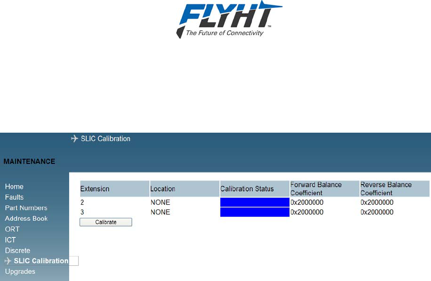
AFIRS 228 Series Installation Manual
250-0019 Confidential and Proprietary to
Rev. -- FLYHT Aerospace Solutions Ltd.
22 April 2013 Page 69
8.3.4 Calibrating SLIC
The SLIC calibration page (see Figure 8-8) is used to set longitudinal balance. The
measurement is made at installation time to improve noise immunity on the twisted pairs
connected to the handsets (extensions 2 and 3).
Figure 8-8 – SLIC Calibration Screen
8.4 Upgrading AFIRS 228 Software
The AFIRS 228 system software is field-upgradeable using the Upgrade function of the
Maintenance Port program.
You can access the software upgrade functionality when logged into the AFIRS maintenance
program in Maintenance Mode, by clicking the Upgrades link available on the left-hand menu of
the AFIRS maintenance program screen.
8.4.1 Upgrade Materials
Make sure you have the following materials available before beginning the upgrade procedure.
A notebook computer with an Ethernet port, running the Microsoft Windows operating
system and a web browser such as Internet Explorer. NOTE: The Ethernet port (TCP/IPv4)
must be configured to obtain an IP address automatically.
Instructions for Continued Airworthiness applicable to the AFIRS Installation.
A standard, straight through Ethernet patch cable.
A copy of the software upgrade file (upgrade.tgz) applicable to the software release.
A copy of the software release notes to identify any changes to functionality or special
upload instructions.
A P-Touch, Label Maker or equivalent with black type on silver/white background labels.
8.4.2 Upgrade Procedure
Before beginning the upload procedure, make sure you have saved the applicable software file
(.tgz) to an accessible location on your laptop. Make sure you review the software release notes
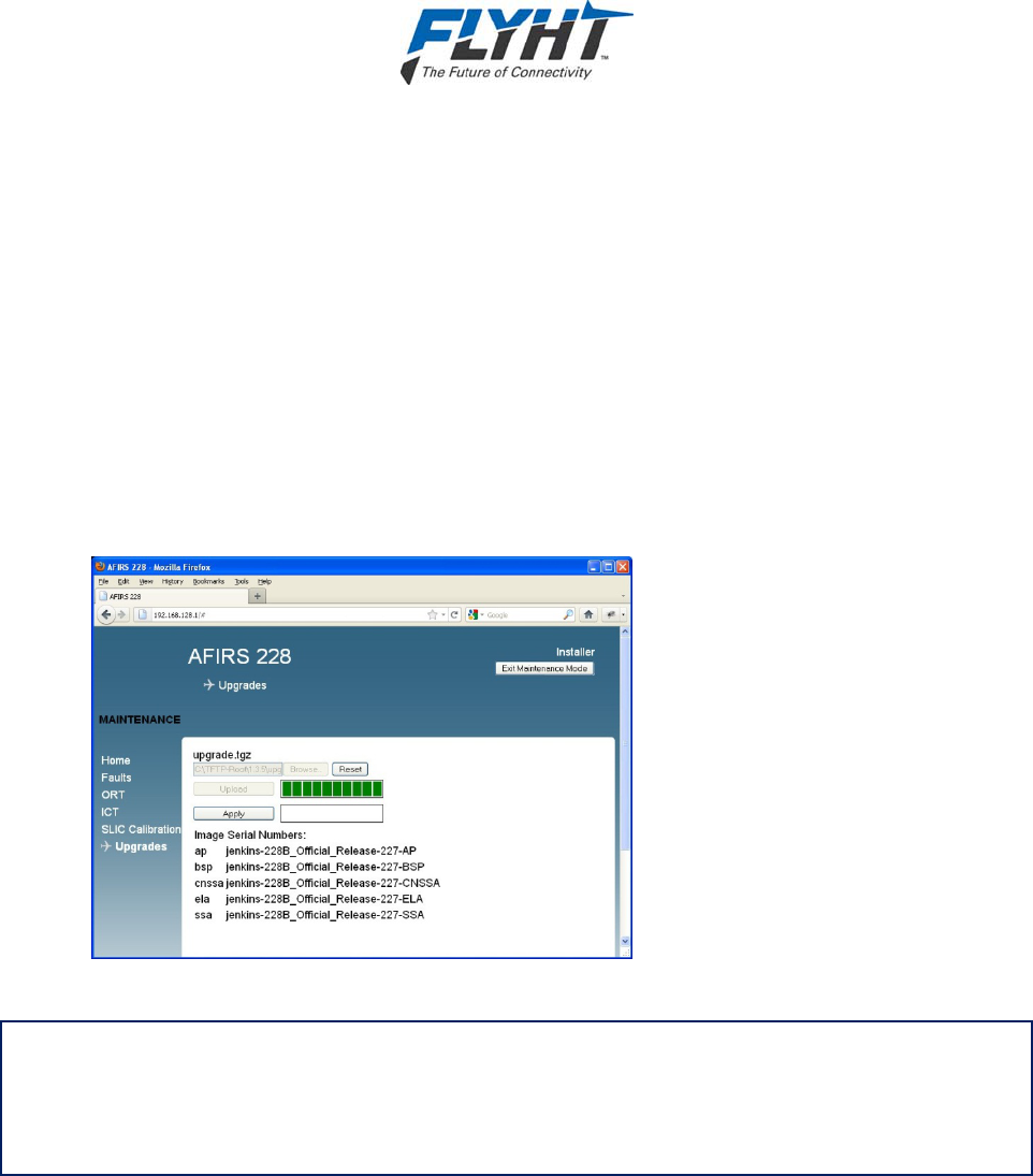
AFIRS 228 Series Installation Manual
Confidential and Proprietary to 250-0019
FLYHT Aerospace Solutions Ltd. Rev. --
Page 70 22 April 2013
and air worthiness instructions for the specific software upgrade you are planning on installing.
Special instructions, specific to each install, are provided in the software release notes.
To upgrade the AFIRS 228 software:
1. From the left-hand menu, click Upgrades.
The Upgrades screen appears.
2. Click Browse…to locate the software file you want to upload to the system.
3. Once you have selected the software file you want to upload, click Upload to start the
upgrade process.
A progress bar appears indicating the file uploading status and lists the image files that
are loading into volatile memory. When the upload is complete the progress bar changes
color from blue to green (see Figure 8-9).
Figure 8-9 – Upgrade Progress
IMPORTANT! If you upload the incorrect file, but have not yet clicked Apply, click Reset to
clear uploaded software.
Reset clears the volatile memory of the software. If you have already applied the software, you
will have to repeat the upgrade to upload and apply the correct software files.
4. To load the software into non-volatile memory and complete the software upgrade
procedure, click Apply.
A progress bar appears indicating that the software file is being installed into the non-
volatile memory of the AFIRS 228 unit. When the progress bar appears green, the
software upgrade has been applied to the unit (see Figure 8-10).
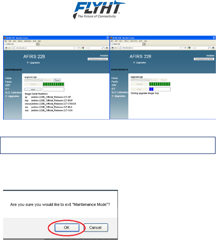
AFIRS 228 Series Installation Manual
250-0019 Confidential and Proprietary to
Rev. -- FLYHT Aerospace Solutions Ltd.
22 April 2013 Page 71
Figure 8-10 – Software Loading Progress Screens
IMPORTANT: To activate the new software load you need to exit Maintenance Mode
and restart the AFIRS 228 unit.
5. To exit Maintenance mode, from the top-right corner of the screen, click Exit
Maintenance Mode.
A confirmation message appears that asks you to confirm that you want to exit
Maintenance Mode (see Figure 8-11).
Figure 8-11 – Exit Message
6. Click OK.
The AFIRS 228 unit automatically restarts and applies the newly installed software. A
progress bar appears indicating the status of the reboot (restart) process.
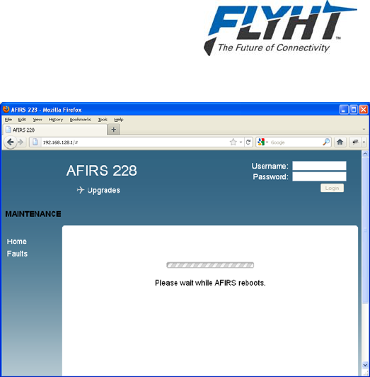
AFIRS 228 Series Installation Manual
Confidential and Proprietary to 250-0019
FLYHT Aerospace Solutions Ltd. Rev. --
Page 72 22 April 2013
Figure 8-12 – Exit Maintenance Mode Progress Bar
7. When the restart is complete, verify that the AFIRS unit is functioning as expected and
verify that correct version of software has been loaded. To verify functionality and check
the software version:
a. Log in to the AFIRS maintenance program.
b. From the Home page, open the General and ARINC tabs to review the system
status to confirm that no faults are displayed.
c. From the left-hand menu, click ORT and review the ORT settings to confirm they
are correct as per the Instructions for Continued Airworthiness (ICA).
d. From the left-hand menu, click ICT and review the ICT settings to confirm they
are correct as per the ICA.
e. From the left-hand menu, click Part Numbers to verify that the part number
displayed for each component matches the required software version and part
number as noted in the release notes or upgrade instructions.
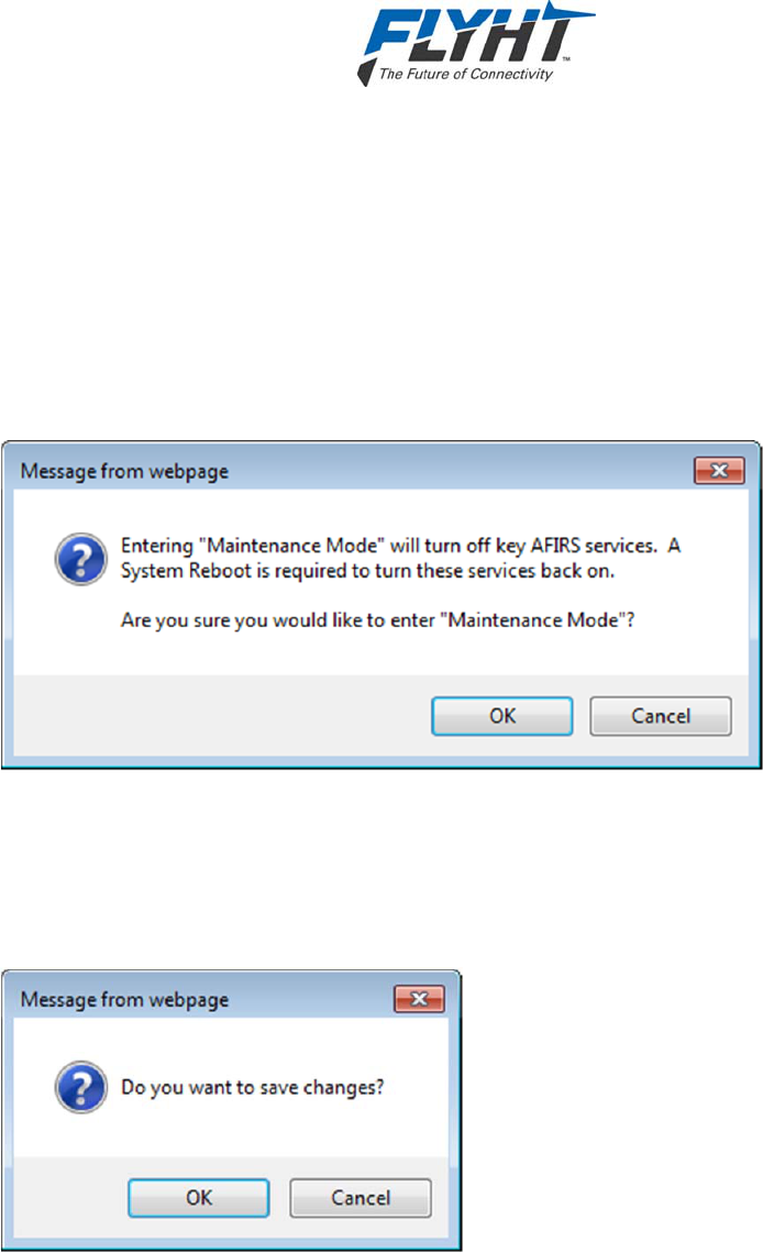
AFIRS 228 Series Installation Manual
250-0019 Confidential and Proprietary to
Rev. -- FLYHT Aerospace Solutions Ltd.
22 April 2013 Page 73
8.5 Exiting Maintenance Mode
To save your changes and configuration data you need to exit maintenance mode.
To exit maintenance mode:
1. In the top-right hand corner of the screen, click Exit Maintenance Mode.
A Message appears notifying you of the number of changes that you have made and asks
you for confirmation (see Figure 8-13).
IMPORTANT! If you click Cancel, your changes are still active but not saved.
Figure 8-13 – Exiting Prompt Message
2. To save your changes, click OK.
A confirmation message appears asking you to confirm that you want to save the changes
that you made (see Figure 8-14). If you click Cancel, you exit maintenance mode and your
changes are NOT saved (i.e. changes are deleted).
Figure 8-14 – Save Prompt
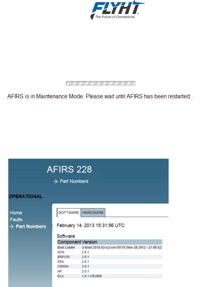
AFIRS 228 Series Installation Manual
Confidential and Proprietary to 250-0019
FLYHT Aerospace Solutions Ltd. Rev. --
Page 74 22 April 2013
3. To save your changes and exit maintenance mode. Click OK.
You exit maintenance mode and the AFIRS 228 restarts. If you try to access the
maintenance interface during this restart, the following message and progress indicator
appears.
Figure 8-15 – Exit and Restart Progress Screen
4. To verify your changes and confirm that you have installed the correct software, from the
Maintenance Program Home page, open the tab Part Numbers.
The Part Numbers screen appears as shown in Figure 8-16. You can check the software
part number status by opening the SOFTWARE tab on the Part Numbers screen.
Figure 8-16 – Software Part Number Status Screen

AFIRS 228 Series Installation Manual
250-0019 Confidential and Proprietary to
Rev. -- FLYHT Aerospace Solutions Ltd.
22 April 2013 Page 75
9. MAINTENANCE AND CHECKOUT
This section provides instructions on post-installation checkout procedures and information on
Instructions for Continued Airworthiness. For detailed operating procedures and additional
system troubleshooting information, refer to the AFIRS 228 Series Operator’s Manual,
document number 250-0022.
9.1 Post-Installation Checkout
9.1.1 Before Power-On Tests
1. Before installing the AFIRS DMU in the mounting tray, confirm that all aircraft interface
wiring is correct as per the aircraft wiring integration design.
2. Confirm that a valid SIM card is installed in the Aircraft Configuration Module (ACM).
3. Set the AFIRS circuit breaker for the Main power source and confirm that 28 VDC power is
available between pins J1C-2 and J1C-3. Pull the circuit breaker and ensure that Main
power is removed.
4. If an Alternate power source is connected, set the AFIRS circuit breaker for the Alternate
power source and confirm that 28 VDC power is available between pins J1C-9 and J1C-3.
Pull the circuit breaker and ensure that Alternate power is removed.
5. Place the AFIRS DMU in the mounting tray and secure the front hold-down.
6. Open the front panel door and confirm that a flash card is installed in the DMU.
Note:
Only FLYHT P/N 502-1180-x flash cards should be used in the AFIRS system. These cards
have been tested to ensure they function correctly in all expected operating environments.
9.1.2 Power-On Tests
1. The cockpit AFIRS FAULT indication should be illuminated when power is not applied to the
AFIRS system.
2. Set the AFIRS circuit breaker for the Main power source. The SYSTEM STATUS indicator
on the front panel of the DMU will illuminate amber indicating that the system is initializing.
Note:
The first time a DMU is installed in an aircraft, the SYSTEM STATUS indicator will typically
remain amber even after it has initialized. This indicates that the system is not fully
operational, in this case because the proper configuration settings have not yet been made.
3. Configure the ICT and ORT in accordance with the procedures contained in section 8. Keep
the laptop connected to the Maintenance Port after finishing the configuration procedure.
4. Once the system resets, the SYSTEM STATUS indicator on the front panel of the DMU will
illuminate amber while the system is initializing; it will then turn green once the system is
operational. The cockpit AFIRS FAULT annunciator should remain illuminated whenever the
SYSTEM STATUS indicator is amber, and extinguish when the SYSTEM STATUS indicator
turns green.

AFIRS 228 Series Installation Manual
Confidential and Proprietary to 250-0019
FLYHT Aerospace Solutions Ltd. Rev. --
Page 76 22 April 2013
Note:
If the SYSTEM STATUS indicator doesn’t turn green after 60 seconds, the system is not fully
operational. This may be because of an incorrect configuration setting, or one of the configured
interfaces is not operational.
9.1.3 Aircraft Systems Interface Tests
Note:
The tests listed in this section are generic in nature and are not intended to be used as a test
plan for any specific aircraft installation. They should only be used by the aircraft systems
integrator as a guide in developing the correct and complete aircraft-specific integration tests.
The aircraft systems integrator’s test plan should ensure that the aircraft and its systems are in
a safe condition for each test to be performed.
9.1.3.1 Alternate Power Test
1. Confirm 28 VDC power is available at both the Main and Alternate power inputs, and that
the AFIRS system is initialized and operating.
2. Remove power from the Main input. Confirm AFIRS continues to operate.
Note:
If AFIRS is configured to provide a shutdown delay, this step can be extended and timed to
verify the AFIRS automatically shuts down at the correct delay time.
3. Remove power from the Alternate input to power down the unit.
4. Apply 28 VDC power to the Alternate power input only. If the Remote Start input pin (J1C-5)
is jumpered to ground, confirm the system initializes properly.
5. If the Remote Start input pin (J1C-5) is connected to an aircraft system, manipulate that
system to provide a ground on the Remote Start input. Confirm the AFIRS system initializes
properly.
6. Restore 28 VDC power to the Main power input.
9.1.3.2 ARINC Databus Interface Tests
1. Using the maintenance terminal, display the AFIRS Home page.
2. Confirm the aircraft system connected to the databus port being tested is operational and
transmitting on the databus.
3. Confirm that the following databuses are shown as operational, as applicable:
a. ARINC 717 Rx Bus
b. ARINC 429 Rx Bus (1-16)
9.1.3.3 MCDU Tests
If installed, confirm AFIRS functionality on each MCDU as follows:
1. On the MCDU Main Menu, “AFIRS” (or “SATCOM”) should be available at one of the Line
Select Keys (LSKs). Press the AFIRS LSK and the AFIRS MAIN page should be displayed.

AFIRS 228 Series Installation Manual
250-0019 Confidential and Proprietary to
Rev. -- FLYHT Aerospace Solutions Ltd.
22 April 2013 Page 77
2. Press the <STATUS LSK. The AFIRS STATUS page should be displayed.
3. Press the <RETURN LSK. The AFIRS MAIN page should be displayed.
9.1.3.4 Serial Port Tests
If installed, confirm AFIRS connectivity to each serial port device as follows:
1. Perform any tests specific to the connected system to confirm that it is communicating with
the AFIRS over the serial port.
9.1.3.5 Ethernet Tests
If installed, confirm AFIRS connectivity to each Ethernet device as follows:
1. Confirm the DMU front panel ETHERNET indicator for the connected port is green. Flashing
green indicates data is being transferred.
2. Perform any tests specific to the connected system to confirm that it is communicating with
the AFIRS over the Ethernet port.
9.1.3.6 Discrete Input Tests
For each discrete input connected, confirm the correct state is detected as follows:
1. Monitor the Discrete Inputs on the maintenance terminal Home page. Manipulate the system
providing the discrete input as required to output the inactive state. Confirm proper display
on the Home page.
2. Manipulate the system providing the discrete input as required to output the active state.
Confirm proper display on the Home page.
9.1.3.7 Discrete Output Tests
For each discrete output connected, confirm the correct aircraft system interface as follows:
1. Using the maintenance terminal, place the AFIRS system in the Maintenance Mode. Click
on the “Discrete Output” link on the left hand side of the screen.
2. Select the discrete output to its inactive state. Confirm proper operation of the interfaced
aircraft system.
3. Select the discrete output to its active state. Confirm proper operation of the interfaced
aircraft system.
4. Exit Maintenance Mode and allow the AFIRS system to restart.
9.1.4 Operational System Tests
Note:
The tests in this section require the aircraft to be powered and outside the hangar in a location
that has a clear view of the Iridium and GPS satellites. Aircraft systems that interface with the
AFIRS must be installed and operational.
These tests also require the AFIRS system to have been activated on the Iridium network by
FLYHT, and for a valid SIM card to be installed in the ACM.

AFIRS 228 Series Installation Manual
Confidential and Proprietary to 250-0019
FLYHT Aerospace Solutions Ltd. Rev. --
Page 78 22 April 2013
9.1.4.1 Date, Time, and Position Tests
1. Using the AFIRS maintenance terminal (ref. section 8.1), navigate to the AFIRS Home page.
2. Confirm the correct date, time, and position (DTP) information is displayed.
3. Note the DTP source being used. If it is an external source, disable that source and confirm
that a different source is being used. Repeat until the system is using the internal GPS
source (if configured active).
4. Restore all disabled DTP sources.
9.1.4.2 Satcom Tests
1. Confirm Iridium satellite network availability (e.g. ‘Ready to Connect’ indication on the
MCDU or ISVM indicator on DMU front panel is green).
2. Using an MCDU or Dial Pad, place a voice call to a ground station. Confirm proper cockpit
indications for a call in progress.
3. Terminate the call from the cockpit. Confirm proper cockpit indications for the ‘Ready to
Connect’ state.
4. Place a call from a ground station to the aircraft. Confirm proper cockpit indications for an
incoming call. Answer the call and confirm proper cockpit indications for a call in progress.
5. Conference in each other extension available in the aircraft. Confirm proper extension
ringing function, conference call functionality, and cockpit indications.
6. Leave the conference call from Extension 1. Confirm the call is still in progress from the
remaining extension(s). Confirm proper cockpit indications for a cabin call in progress.
7. Preempt the cabin call and confirm that the cockpit now has control of the voice channel.
Confirm proper cockpit indications.
8. Place a call from a ground station to the aircraft. Reject the call. Confirm proper cockpit
indications.
9. Place a call from a ground station to the aircraft. Allow call to go unanswered. Confirm
proper ring sequencing, eventual call termination, and proper cockpit indications.
10. Place a call from a cabin extension to a ground station. Confirm proper cockpit indications
for a cabin call in progress. Set up a camp-on call from the cockpit. Terminate the call in the
cabin and confirm that the camped-on call is automatically initiated. Confirm proper cockpit
indications.
11. Terminate call at the ground station. Confirm proper cockpit indications.
12. Select the ‘Cabin Lock’ function and confirm proper cockpit indications. Confirm that cabin
extensions cannot place a voice call.
13. If configured to be able to turn ‘Iridium Off’ with the ‘All Off’ option, turn ‘Iridium Off’ and
confirm proper cockpit indications. Confirm that a voice call cannot be made to or from the
aircraft. Turn Iridium back on and confirm proper operation and cockpit indications.

AFIRS 228 Series Installation Manual
250-0019 Confidential and Proprietary to
Rev. -- FLYHT Aerospace Solutions Ltd.
22 April 2013 Page 79
9.1.4.3 Datalink Tests
1. If Uptime access is available, confirm the power-on report has been received from the
aircraft.
2. Confirm EFB datalink functionality is available.
3. If so configured, turn ‘Iridium Off’ and confirm proper cockpit indications. Confirm that data
transmissions cease from the aircraft. Turn Iridium back on and confirm proper operation
and cockpit indications.
9.1.5 EMI Tests
Each AFIRS aircraft installation should be tested for electromagnetic interference in accordance
with procedures developed by the aircraft systems integrator. The tests should be developed to
ensure that there is no objectionable interference between the AFIRS and other aircraft
systems. This can include ground tests with engine running and flight tests as required.
9.2 Instructions for Continued Airworthiness
The aircraft systems integrator is responsible to provide Instructions for Continues Airworthiness
(ICA) for the AFIRS system specific to the aircraft installation. The general content in this
Installation Manual may be referenced by the aircraft systems integrator when developing the
ICA.

AFIRS 228 Series Installation Manual
Confidential and Proprietary to 250-0019
FLYHT Aerospace Solutions Ltd. Rev. --
Page 80 22 April 2013
THIS PAGE INTENTIONALLY LEFT BLANK

AFIRS 228 Series Installation Manual
250-0019 Confidential and Proprietary to
Rev. -- FLYHT Aerospace Solutions Ltd.
22 April 2013 Page 81
Appendix A – ICT Worksheet
ICTGroupICTParameterNameValue
AircraftInfoModel/Type(Text–24Characters)
SerialNumber(Text–24Characters)
IridiumSDUNo. SDU1
SDU2
IridiumDataMode DEDICATED
MULTIPLEXED
GPSInternalGPS ACTIVE
INACTIVE
ARINC717Format NONE
HBP
BPRZ
BusSpeed 64STD
64REV
128
256
512
1024
ICT–ARINC429Receivers
FunctionDTPICAO12345678910111213 14 15 16
NONE
GENERIC429
ACARS1
ACARS2
AIRBUSCFDS
A702/AFMS1
A702/AFMS2
A702/AFMS3
GAMA429FMS1
GAMA429FMS2
GAMA429FMS3
CMA‐9000FMS1
CMA‐9000FMS2
CMA‐9000FMS3

AFIRS 228 Series Installation Manual
Confidential and Proprietary to 250-0019
FLYHT Aerospace Solutions Ltd. Rev. --
Page 82 22 April 2013
ICT–ARINC429Receivers
FunctionDTPICAO12345678910 11 12131415 16
BASICDTP1
BASICDTP2
PL4/21GPBUS51
PL4/21GPBUS52
A739MCDU1
A739MCDU2
A739MCDU3
MODES1
MODES2
SpeedLO
HI
Parity
ODD
EVEN
NONE
ICT–ARINC429Transmitters
Function123456
NONE
A739MCDU
ACARS(228SOnly)
GPBUS1
GPBUS2
GPBUS3
GPBUS4
SpeedLO
HI
AFIRS 228 Series Installation Manual
250-0019 Confidential and Proprietary to
Rev. -- FLYHT Aerospace Solutions Ltd.
22 April 2013 Page 83
ICT–SerialPorts ICT–SerialPorts
FunctionReceiveTransmit Parameter1234
12341234
DataBits
5
NONE 6
GENERIC 7
EFB1 8
EFB2
Parity
NONE
EFB3 ODD
Type232 EVEN
422
StopBits1
Speed
2.4 2
4.8
FlowControl
NONE
9.6 XON/XOFF
19.2 RTS/CTS
ICT–EthernetPorts
Function1A 2B 3B 4B
NONE
NOTMONITORED
MONITORED

AFIRS 228 Series Installation Manual
Confidential and Proprietary to 250-0019
FLYHT Aerospace Solutions Ltd. Rev. --
Page 84 22 April 2013
ICT–DiscreteInputs
Function2345678910 11 12 131415
NONE
GENERIC
CABINLOCK
CHIMERESET
ENDCALL
EVENT
IRIDIUMOFF
MICON
PARKBRAKE
SYSRESET
WOW2
SignalOPEN/GND
OPEN/28V
LogicACTIVELO
ACTIVEHI
ICT–DiscreteOutputs
Function12345678
NONE
CABINLOCK
CALLLIGHT
EXT2CALL
EXT3CALL
GPSLINK
IRIDIUMOFF
ISVMLINK
ISDMLINK(228SOnly)
TEXTMSG
LogicACTIVELO
ACTIVEHI
ChimeActiveTime(100to6,000ms)______ms
InactiveTime(100to6,000ms)______ms

AFIRS 228 Series Installation Manual
250-0019 Confidential and Proprietary to
Rev. -- FLYHT Aerospace Solutions Ltd.
22 April 2013 Page 85
SatcomICTParameterNameValue
Extension1Location NONE
COCKPIT
CABIN
SidetoneLevel(‐20to‐3dB)____dB
NoiseCancelling ENABLED
DISABLED
MicOnConfig SWITCHEDPTT
LATCHEDACP
ControlSource MCDU
EXT3DTMF
MicGain(Pre‐ADC)(0to59dB)____dB
Extension2Location NONE
COCKPIT
CABIN
Volume(1to5dB)____dB
SidetoneLevel(‐20to‐3dB)____dB
NoiseCancelling ENABLED
DISABLED
Extension3Location NONE
COCKPIT
CABIN
Volume____dB
SidetoneLevel(‐20to‐3dB)____dB
NoiseCancelling ENABLED
DISABLED

AFIRS 228 Series Installation Manual
Confidential and Proprietary to 250-0019
FLYHT Aerospace Solutions Ltd. Rev. --
Page 86 22 April 2013
THIS PAGE INTENTIONALLY LEFT BLANK

AFIRS 228 Series Installation Manual
250-0019 Confidential and Proprietary to
Rev. -- FLYHT Aerospace Solutions Ltd.
22 April 2013 Page 87
Appendix B – ORT Worksheet
ORTGroupORTParameterNameValue
AircraftInfoRegistration/FIN(Text–24Characters)
ICAO24‐BitAddress
FDMReservedSpace(0.1to4.0GB)______GB
Power
Management
ShutdownDelayTime(0to60min.) ALWAYSON
______min.
MCDUSystemName AFIRS
SATCOM
AFIR/SATCM
CallPriorityName(1‐4) EMERGENCY,SAFETY,NON‐SAFETY,
PUBLIC
EMERGENCY,OPERATIONALHIGH,
OPERATIONALLOW,PUBLIC
AllowIridiumOff YES
NO
IridiumIridiumOffMode ALLOFF
DATAOFF
AirToGround
Calls
ChimeonConnect YES
NO
CIPTransition INITIATED
CONNECTED
CallProgressTones NORTHAMERICAN
EUROPEAN
DefaultCall
Priority
Extension1 1
2
3
4
Extension2 1
2
3
4
Extension3 1
2
3
4
Directory
(Ext1Only)
DirectoryCount(1to10)
Directory1Name
(Text–10Characters)

AFIRS 228 Series Installation Manual
Confidential and Proprietary to 250-0019
FLYHT Aerospace Solutions Ltd. Rev. --
Page 88 22 April 2013
ORTGroupORTParameterNameValue
Directory2Name
(Text–10Characters)
Directory3Name
(Text–10Characters)
Directory4Name
(Text–10Characters)
Directory5Name
(Text–10Characters)
Directory6Name
(Text–10Characters)
Directory7Name
(Text–10Characters)
Directory8Name
(Text–10Characters)
Directory9Name
(Text–10Characters)
Directory10Name
(Text–10Characters)
AllowManual
Dialing
Ext1 YES
NO
Ext2 YES
NO
Ext3 YES
NO
GroundtoAir
Calls
AllowLowPriorityCallsinCockpit YES
NO
RingType CONCURRENT
SEQUENTIAL
SequentialRingRingOrder 123213312
132231321
Ext1RingCount(3to10)
Ext2RingCount(3to10)
Ext3RingCount(3to10)
ConcurrentRingRingCount(3to10)

AFIRS 228 Series Installation Manual
250-0019 Confidential and Proprietary to
Rev. -- FLYHT Aerospace Solutions Ltd.
22 April 2013 Page 89
ORTGroupORTParameterNameValue
Ext1RingRing YES
NO
Call_Light/Chime FLASHING/MULTI‐STROKE
FLASHING/SINGLE‐STROKE
STEADY/SINGLE‐STROKE
RingTone YES
NO
Ext2RingRing YES
NO
Re‐RingTime(1to10)
Re‐RingCount(1to10)
Call_Light FLASHING
STEADY
Ext3RingRing YES
NO
Re‐RingTime(1to10)
Re‐RingCount(1to10)
Call_Light FLASHING
STEADY
SafetyServices
(228SOnly)
ServiceProvider ARINC
SITA

AFIRS 228 Series Installation Manual
Confidential and Proprietary to 250-0019
FLYHT Aerospace Solutions Ltd. Rev. --
Page 90 22 April 2013
THIS PAGE INTENTIONALLY LEFT BLANK

AFIRS 228 Series Installation Manual
250-0019 Confidential and Proprietary to
Rev. -- FLYHT Aerospace Solutions Ltd.
22 April 2013 Page 91
Appendix C – Environmental Qualification Forms
The following two forms are provided for the AFIRS 228B DMU and AFIRS 228 ACM
respectively.

AFIRS 228 Series Installation Manual
Confidential and Proprietary to 250-0019
FLYHT Aerospace Solutions Ltd. Rev. --
Page 92 22 April 2013
RTCA DO-160F Environmental Qualification Form
Nomenclature: Data Management Unit (DMU)
Model: AFIRS 228B
Part Number: 502-2001-01
Manufacturer: FLYHT, 200W, 1144 – 29 Avenue NE, Calgary, AB, Canada T2E 7P1
Conditions Section Description of Tests Conducted
Temperature and Altitude 4.0 Categories A2, F2
In-Flight Loss of Cooling 4.5.5 Category X (not tested)
Temperature Variation 5.0 Category B
Humidity 6.0 Category A
Operational Shock & Crash Safety 7.0 Category D
Vibration 8.0 Categories S (Curves C & L), U2
Explosive Atmosphere 9.0 Category X (not tested)
Waterproofness 10.0 Category X (not tested)
Fluids Susceptibility 11.0 Category X (not tested)
Sand & Dust 12.0 Category X (not tested)
Fungus 13.0 Category X (not tested)
Salt Fog Test 14.0 Category X (not tested)
Magnetic Effect 15.0 Category Z
Power Input 16.0 Category Z (XI)
Voltage Spike 17.0 Category A
Audio Frequency Susceptibility 18.0 Category Z
Induced Signal Susceptibility 19.0 Category ZW
Radio Frequency Susceptibility 20.0 Category ST
Radio Frequency Emission 21.0 Category M
Lightning Induced Transient Susceptibility 22.0 Category X (not tested)
Lightning Direct Effects 23.0 Category X (not tested)
Icing 24.0 Category X (not tested)
Electrostatic Discharge 25.0 Category A
Fire, Flammability 26.0 Category C
Remarks:
1. Section 26.0 was tested as per DO-160G; all other tests as per DO-160F.

AFIRS 228 Series Installation Manual
250-0019 Confidential and Proprietary to
Rev. -- FLYHT Aerospace Solutions Ltd.
22 April 2013 Page 93
RTCA DO-160F Environmental Qualification Form
Nomenclature: Aircraft Configuration Module (ACM)
Model: AFIRS 228
Part Number: 502-3001-01
Manufacturer: FLYHT, 200W, 1144 – 29 Avenue NE, Calgary, AB, Canada T2E 7P1
Conditions Section Description of Tests Conducted
Temperature and Altitude 4.0 Categories A2, F2
In-Flight Loss of Cooling 4.5.5 Category X (not tested)
Temperature Variation 5.0 Category B
Humidity 6.0 Category A
Operational Shock & Crash Safety 7.0 Category D
Vibration 8.0 Categories S (Curves C & L), U2
Explosive Atmosphere 9.0 Category X (not tested)
Waterproofness 10.0 Category X (not tested)
Fluids Susceptibility 11.0 Category X (not tested)
Sand & Dust 12.0 Category X (not tested)
Fungus 13.0 Category X (not tested)
Salt Fog Test 14.0 Category X (not tested)
Magnetic Effect 15.0 Category Z
Power Input 16.0 Category Z (XI)
Voltage Spike 17.0 Category A
Audio Frequency Susceptibility 18.0 Category Z
Induced Signal Susceptibility 19.0 Category ZW
Radio Frequency Susceptibility 20.0 Category ST
Radio Frequency Emission 21.0 Category M
Lightning Induced Transient Susceptibility 22.0 Category X (not tested)
Lightning Direct Effects 23.0 Category X (not tested)
Icing 24.0 Category X (not tested)
Electrostatic Discharge 25.0 Category A
Fire, Flammability 26.0 Category C
Remarks:
1. Section 26.0 was tested as per DO-160G; all other tests as per DO-160F.

AFIRS 228 Series Installation Manual
Confidential and Proprietary to 250-0019
FLYHT Aerospace Solutions Ltd. Rev. --
Page 94 22 April 2013
FLYHT Aerospace Solutions Ltd.
200W, 1144 – 29th Avenue NE
Calgary, Alberta, Canada T2E 7P1
Telephone: 1-403-250-9956
Toll Free: 1-866-250-9956
Fax: 1-403-291-9717
E-mail: support@flyht.com
Website: http://flyht.com