FLYSKY RC MODEL TECHNOLOGY FG400 Noble(NB4) User Manual
FLYSKY RC MODEL TECHNOLOGY CO., LTD Noble(NB4)
User manual

USER MANUAL
Copyright ©2018 Flysky Technology co., ltd

Thank you for purchasing our product, an ideal radio system for beginners or
experienced users.
In order to ensure your safety, and the safety of others, read this manual carefully
before using this product. If you encounter any problem during use, refer to this
manual rst. If the problems persists, contact your local dealer or visit our service and
support website:
www.ysky-cn.com
1. Safety..................................................................................................................................1
1.1 Safety Symbols ........................................................................................................................................................................1
1.2 Safety Guide .............................................................................................................................................................................1
2. Introduction.......................................................................................................................2
2.1 System Features ......................................................................................................................................................................2
2.2 Transmitter Overview ............................................................................................................................................................3
2.3 Receiver Overview ..................................................................................................................................................................6
2.3.1 Status Indicator ............................................................................................................................................................................6
3 Getting Started...................................................................................................................6
3.1 Transmitter Battery Installation .........................................................................................................................................7
4. Operation Instructions.............................................................................................8
4.1 Power On ...................................................................................................................................................................................8
4.2 Binding .......................................................................................................................................................................................8
4.3 Transmitter LED Indicator......................................................................................................................................................8
4.4 Power Off .................................................................................................................................................................................8
5. System Interface...............................................................................................................9
6. Function Settings............................................................................................................10
6.1 Reverse ....................................................................................................................................................................................10
6.2 End Points ...............................................................................................................................................................................10
6.3 Subtrim ....................................................................................................................................................................................10
6.4 Steering Exponential ...........................................................................................................................................................11
6.5 Steering Speed.......................................................................................................................................................................11
6.6 Steering Mix ...........................................................................................................................................................................11
6.7 Throttle Neutral ....................................................................................................................................................................12
6.8 Throttle Exponential.......................................................................................................................................................12
6.9 Throttle Curve........................................................................................................................................................................12
6.10 A.B.S.......................................................................................................................................................................................13
6.11 Throttle Speed ....................................................................................................................................................................14
6.12 Throttle Middle...................................................................................................................................................................14
6.13 Throttle Idle Up...................................................................................................................................................................14
6.14 Engine Cut.............................................................................................................................................................................15
6.15 Boat Mode............................................................................................................................................................................16
6.16 Brake Mixing........................................................................................................................................................................16
6.17 Mixes......................................................................................................................................................................................16
6.18 Display Servos.....................................................................................................................................................................17
6.19 Race Timers..........................................................................................................................................................................17
6.20 Buttons Assign.....................................................................................................................................................................17
6.21 Models...................................................................................................................................................................................18
7. RX Setup ..........................................................................................................................19
7.1 Bind With A Receiver ..........................................................................................................................................................19
7.2 Failsafe .....................................................................................................................................................................................19
8. System .............................................................................................................................20
8.1 Backlight Timeout.................................................................................................................................................................20
8.2 Bind With A Receiver............................................................................................................................................................20
8.3 System Sound........................................................................................................................................................................20
8.4 Vibration .................................................................................................................................................................................20
8.5 LED Light..................................................................................................................................................................................21
8.6 Language ................................................................................................................................................................................21
8.7 Auto Power Off .....................................................................................................................................................................21
8.8 Radio Frequency Setup.......................................................................................................................................................21
8.9 Stick Calibration.....................................................................................................................................................................21
8.10 Firmware Update................................................................................................................................................................22
8.11 Factory Reset........................................................................................................................................................................23
8.12 About Noble.........................................................................................................................................................................23
9. Product Specifications...................................................................................................23
10. Package Contents.........................................................................................................24
11.Certification...................................................................................................................25
11.1 DoC Declaration .................................................................................................................................................................25
11.2 CE Warning.....................................................................................................................................................................................25
11.3 Enviromentally Friendly Disposal..................................................................................................................................25
11.4 Appendix 1 FCC Statement.............................................................................................................................................26
1
• Misuseofthisproductmayleadtoseriousinjuryordeath.Toensurethesafetyofyou
andyourequipment,readthismanualandfollowtheinstructions.
• Makesuretheproductisproperlyinstalledinyourmodel.Failuretodosomayresultin
seriousinjury.
• Makesuretodisconnectthereceiverbatterybeforeturningothetransmitter.Failure
todosomayleadtounintendedoperationandcauseanaccident.
• Ensurethatallmotorsoperateinthecorrectdirection.Ifnot,adjustthedirectionrst.
• Makesurethemodelieswithinacertaindistance.Otherwise,itwouldcauselossof
control.
• Donotusetheproductatnightorinbadweatherlikerainorthunderstorm.Itcan
causeerraticoperationorlossofcontrol.
• Donotusetheproductwhenvisibilityislimited.
• Donotusetheproductonrainorsnowdays.Anyexposuretomoisture(waterorsnow)
maycauseerraticoperationorlossofcontrol.
• Interferencemaycauselossofcontrol.Toensurethesafetyofyouandothers,donot
operateinthefollowingplaces:
• Near any site where other radio control activity may occur
• Near power lines or communication broadcasting antennas
• Near people or roads
• On any body of water when passenger boats are present
• Donotusethisproductwhenyouaretired,uncomfortable,orundertheinuenceof
alcoholordrugs.Doingsomaycauseseriousinjurytoyourselforothers.
• The2.4GHzradiobandislimitedtolineofsight.Alwayskeepyourmodelinsightasa
largeobjectcanblocktheRFsignalandleadtolossofcontrol.
• Nevergripthetransmitterantennaduringoperation.Itsignicantlydegradessignal
qualityandstrengthandmaycauselossofcontrol.
• Donottouchanypartofthemodelthatmaygenerateheatduringoperation,or
immediatelyafteruse.Theengine,motororspeedcontrol,maybeveryhotandcan
causeseriousburns.
Prohibited Mandatory
1.Safety
1.1SafetySymbols
Pay close attention to the following symbols and their meanings. Failure to follow these warnings could cause
damage, injury or death.
1.2SafetyGuide
Warning • Notfollowingtheseinstructionsmayleadtomajorinjuries.
Danger • Notfollowingtheseinstructionsmayleadtoseriousinjuriesordeath.
Attention • Notfollowingtheseinstructionsmayleadtominorinjuries.

2
2.Introduction
This product uses the 2.4GHz Third Generation AFHDS 3 protocol. The NB4 and FGr4 constatute a 4 channel system,
compatible with model cars, boats and other models.
2.1SystemFeatures
AFHDS3 (third-generation automatic frequency hopping digital system) is a newly developed digital wireless system.
It is compatible with single antenna bidirectional real-time data packet transmission and data stream transmission.
With the advantages that come with the WS2A wireless system and the new 2.4GHz chip, the system can dynamically
set: number of channels, channel resolution, range, anti-interference requirements and latency to meet the needs
of dierent users.
SingleAntennaBidirectionalReal-timeDataTransmission
The receiver can receive data from the transmitter and the transmitter can receive data from the receiver, this
includes data from sensors, such as temperature and speed and support the i-BUS. This gives more control
over the aircraft and constant information on its current status.
UncorrectedDataTransmission
The independent uncorrected data transmission module is built into RF system; it can send many different
types of data including flight control data.
IntelligentRFconguration
Depending on hardware, certification, the amount of data to be transmitted, anti-interference, latency and
distance requirements, the system intelligently adapts the corresponding RF configuration to meet the
requirements of the user.
Multi-channelFrequencyHopping
This systems bandwidth ranges from 2.402GHz to 2.480GHz. This band is divided in 140 channels. Each
transmitter hops between 16 channels (32 for Japanese and Korean versions) in order to reduce interference
from other transmitters.
UniqueIDRecognitionSystem
Each transmitter and receiver has it's own unique ID. Once the transmitter and receiver have been paired, they will
only communicate with each other, preventing other systems accidentally connecting to or interfering with the
systems operation.
LowPowerConsumption
The system is built using highly sensitive low power consumption components, maintaining high receiver
sensitivity, while consuming as little as one tenth the power of a standard FM system, dramatically extending
battery life.
3
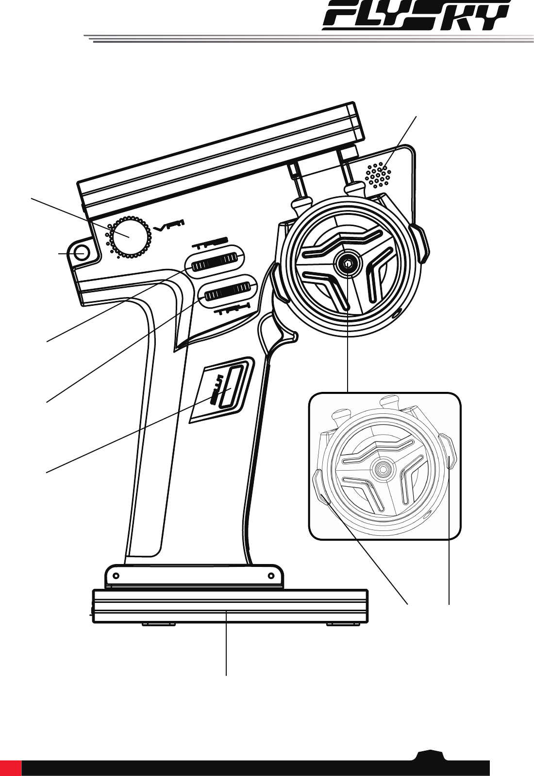
2.2TransmitterOverview
Speaker
VR1
Lanyard Eye
TR3
TR4
SW1
Battery
SW2 SW3
4
VR1
TR3
TR4
SW1
Grip
Trigger size adjustment
Speaker
Trigger spring adjsustment
Battery Port
USB Port (Charging)
Power Button
USB Port (Power Out)
Lanyard Eye
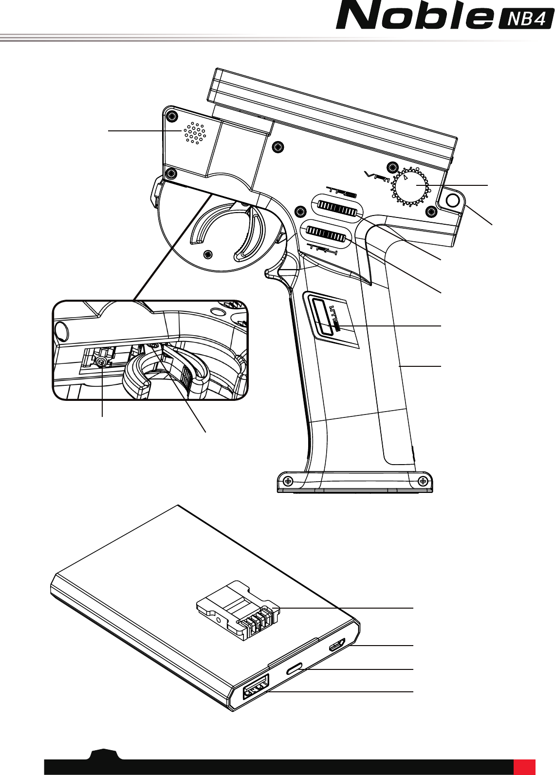
5
Screen
RGB LED
Power
Button
TH Trim
ST Trim
Wheel
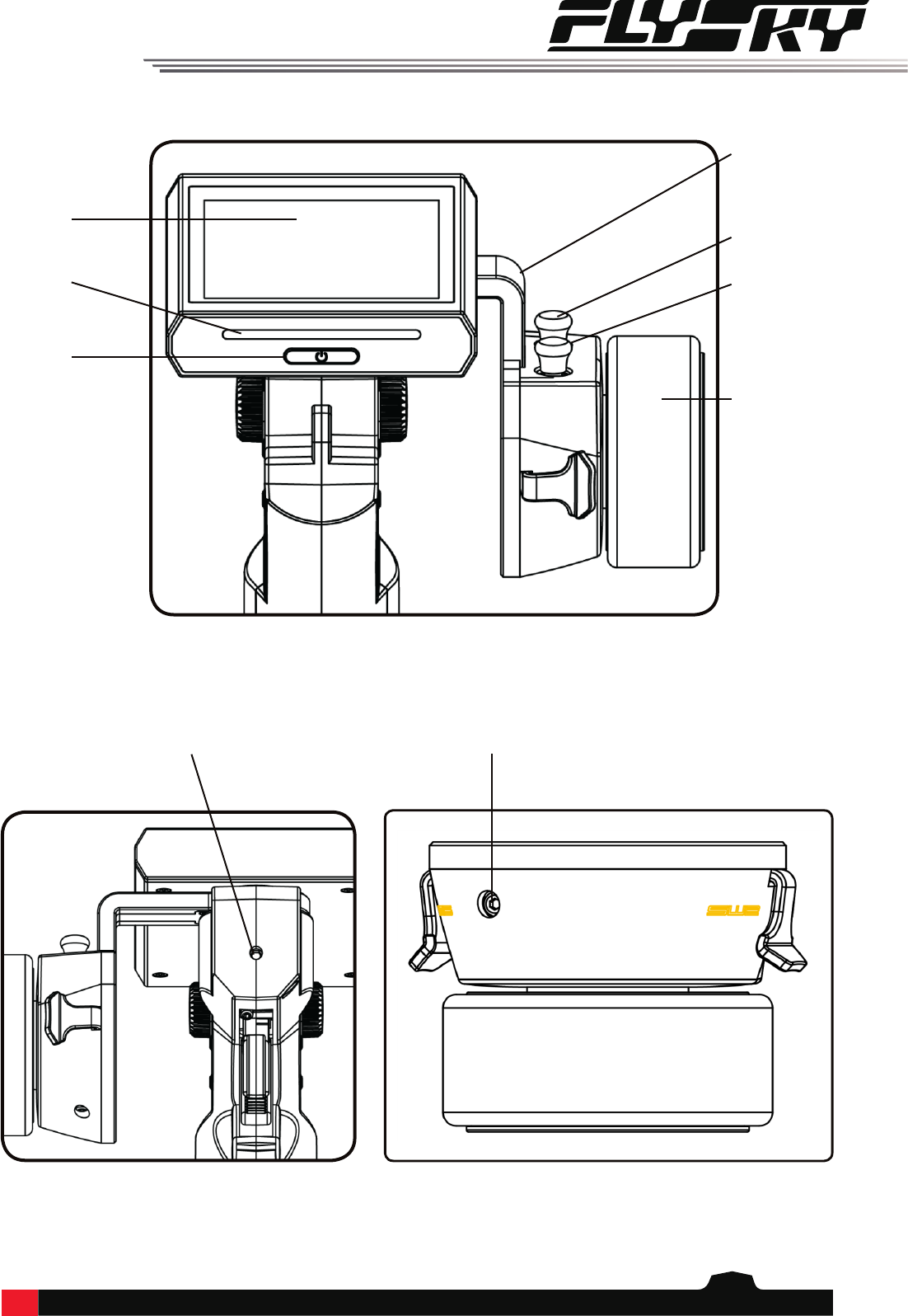
Trigger Position Adjustment Screw
Adjustable
Arm
Wheel Tension Adjustment Screw
6
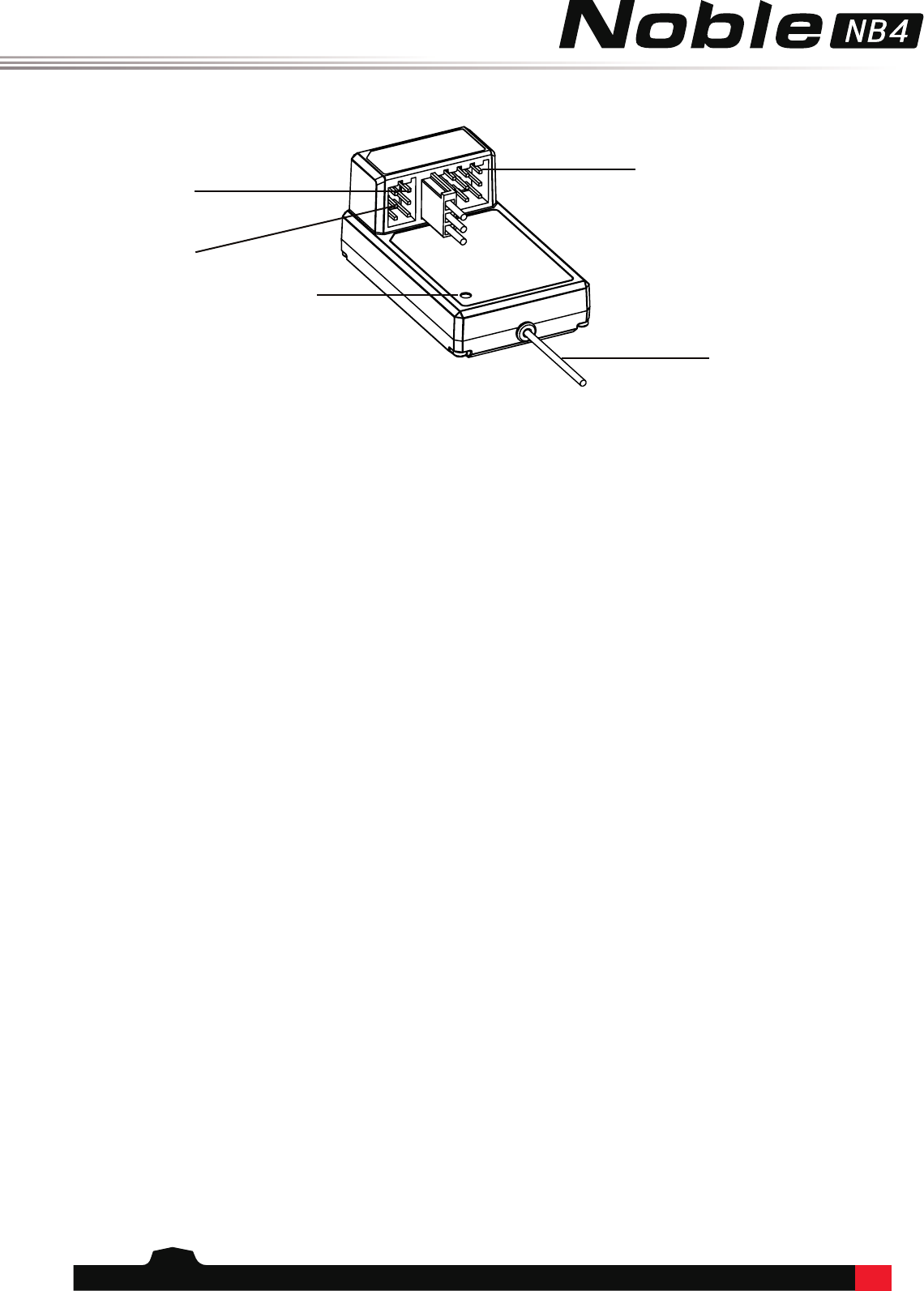
2.3ReceiverOverview
2.3.1StatusIndicator
The status indicator is used to indicate the power and working status of the receiver.
• O: The power is not connected.
• Lit in red: The receiver is on and working.
• Flashing quickly: The receiver is binding.
• Flashing slowly: The bound transmitter is o or signal is lost.
SERVO
SENS
BIND
Antenna
Status Indicator
7
3.GettingStarted
Before operation, install the battery and connect the system as instructed below.
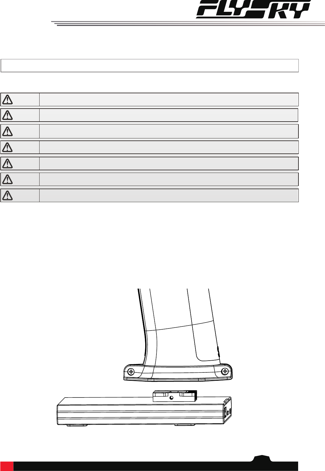
3.1TransmitterBatteryInstallation
Danger • Onlyuseincludedbatteries
Danger • Donotopen,disassemble,orattempttorepairthebattery.
Danger • Donotcrush/puncturethebattery,orshorttheexternalcontacts.
Danger • Donotexposetoexcessiveheatorliquids.
Danger • Donotdropthebatteryorexposetostrongshocksorvibrations.
Danger • Alwaysstorethebatteryinacool,dryplace.
Danger • Donotusethebatteryifdamaged.
The NB4 has 2 batteries, one located in the handle and one in the removeable base.
To attach the base:
1. Line up the base so that the transmitter handle has a slight over hang on the back.
2. Carefully insert the base contacts into the hole in the bottom of the handle.
3. Hold the handle rmly and pull the battery backwards. When it is secure you should hear
a click.
8
4.OperationInstructions
After setting up, follow the instructions below to operate the system.
4.1PowerOn
Follow the steps below to turn on the transmitter:
1. Make sure that:
• The battery is fully charged and installed correctly.
• The receiver is installed correctly and powered down.
2. Hold the power button until the screen turns on.
3. Connect the power supply to the receiver.
Note • Operatewithcautioninordertoavoiddamageorinjury.
Note • Makesurethatthethrottleisatitslowestpositionandtheswitchesaresettotheirup
position.
4.2Binding
The transmitter and receiver have been pre-bound before delivery.
1. Connect the bind cable to the receiver's B/VCC port.
2. Connect power to any other port.
3. Select "Bind With A Receiver" in the transmitter's RX Setup menu.
4. Once binding is complete the transmitter will exit bind mode. Remove the power and bind cable from the
receiver then apply power to the B/VCC port.
5. Check to make sure everything functions as expected. If not repeat the steps above.
If you are using another transmitter or receiver, follow the steps below to bind the transmitter and receiver:
4.4PowerO
Danger • Makesuretodisconnectthereceiverpowerbeforeturningothetransmitter.Failure
todosomayleadtodamageorseriousinjury.
Follow the steps below to turn o the system:
1. Disconnect the receiver power.
2. Hold the transmitters power button until the screen turns o.
4.3TransmitterLEDIndicator
This LED has six colors, green, blue, cyan, red, yellow, white and o which can be set according to user preference.
To change the LED color see the LED Strip section of this user manual.
9
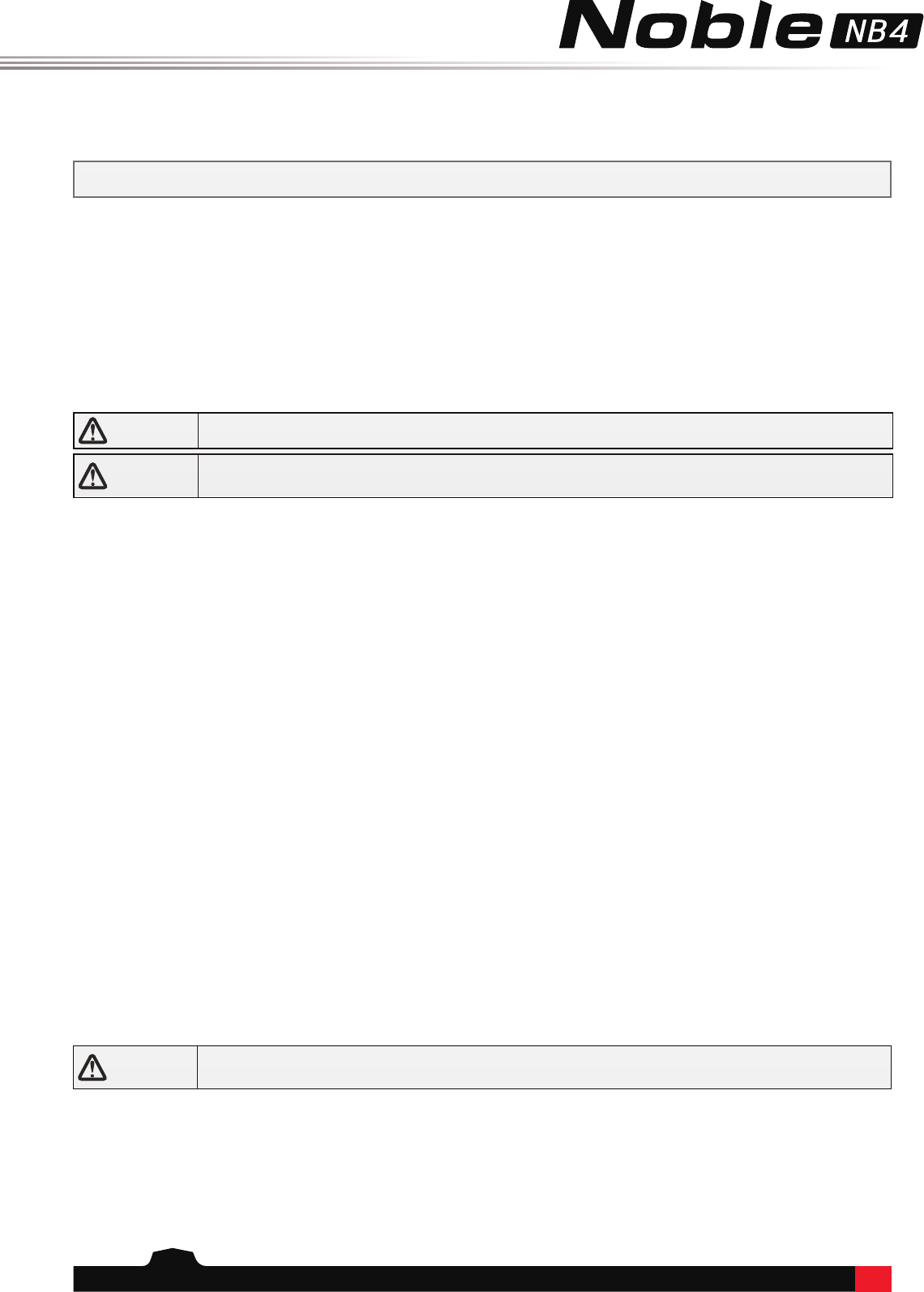
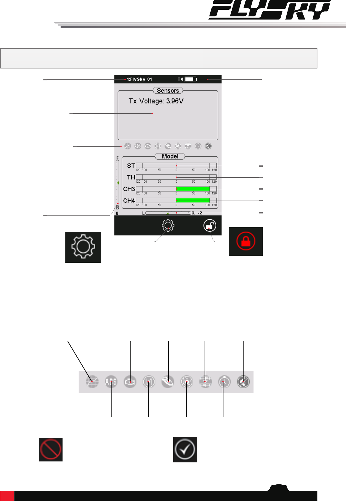
The function status bar displays the status of various functions. If the function is a darker color then
it is active, if it is slightly see through then it is inactive.
5.SystemInterface
Function Status Bar
Trigger Trim Steering Trim
Channel 4
Channel 3
Throttle Channel
Steering Channel
Model Name
Sensors
The main interface mainly displays information related to the model, such as transmitter voltage information,
function status and so on.
To be added
Hold the lock icon for 2
seconds to lock or unlock the
screen.
Menu Icon
EXP Engine Cut Boat Mode Mixes System Sound
A.B.S. Throttle Idle
Up
Brake Mix Race Timers
FunctionStatusBar
Function is not active, touch this
icon, or assign activation to a
switch to activate the function.
Function is active, touch this
icon or assign activation to a
swith to turn the function o.
10
6.FunctionSettings
This section details functions and their use.
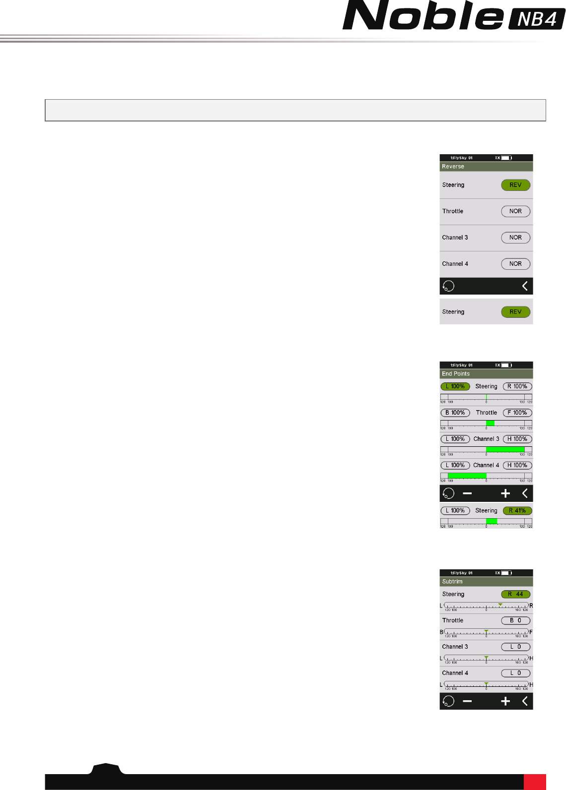
6.1Reverse
6.2EndPoints
Use:
1. Touch the box next to the channels name. If the channel is in normal mode the box
will display "NOR", if it is reversed it will display "REV".
2. Test to make sure everything is working as expected.
Setup:
1. Touch a low or high endpoint box on a channel or move the control to the diection
you wish to limit. The selected endpoint will be highlighted in green.
2. Use the + and - keys to change the end point position. The maximum is 120% and
minimum is 0%.
3. Test to make sure everything is working as expected.
Setup:
1. Touch the box next to the channel name to select it. When selected the box will be
highlighted in green.
2. Use the + and - keys to change subtrim position.
3. Test to make sure everything is working as expected.
The Reverse function is used to correct a servo or motor's direction in relation to the
systems controls. For example, if a steering servo is mounted upside down in order to t
inside a model, when the system's steering wheel is turned, the servo will move in the
opposite direction. To x this, all we need to do is reverse CH1.
Endpoints are the limits of the channels range of movement. There are two endpoints,
a low endpoint and a high end point.
Subtrim is used to change the center point for each channel. For example, if a car’s
wheels are slightly out of aline-ment, even when the transmitter wheel is not being
touched, subtrim can be used to correct the alignment.
6.3Subtrim
11
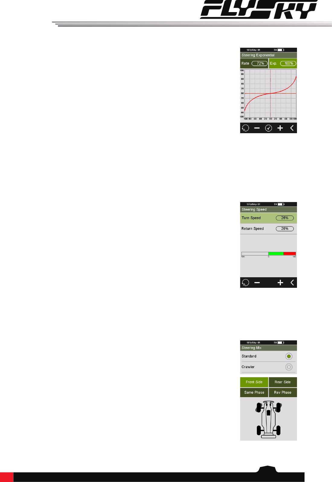
This function changes the steering channel's response curve. There are 2 main
parameters:
• Rate: Changes the outer limits of the steering, the default and maximum is
100%.
• Exp. (Exponential): Changes the steering curve, which changes the response of
the steering wheel. The Exp. setting can be positive or negative.
Changes to the rate and exponential can be seen on the graph located in the center of
the screen. The system also gives a real-time readout of the channel's current position.
Setup:
1. Touch rate or EXP.
2. Use the + and - icons to raise or lower the percentage as needed.
3. Repeat for the other setting as needed.
4. Test to make sure everything is working as expected.
6.4SteeringExponential
6.5SteeringSpeed
6.6SteeringMix
Steering Speed changes the speed that the steering channel moves. This function is also
used to simulate a realistic wheel turn speed for scale models.
Turn Speed: Slows down the steering movement when moving away from the center
point.
Return Speed: Slows down steering movement when moving towards the center point.
Setup:
1. Touch "Turn Speed" or "Return Speed" to select it. When selected the box will turn
green.
2. Use the + and - icons to change the turning speed percentage.
3. Repeat with other setting as needed.
4. Test to make sure everything works as expected.
This function changes which wheels are involved in steering, front, rear, or 4-wheel
steering. It is set to [Standard] by default, which means front wheel steering.
To change steering mode select "Crawler" then select the desired steering type.
Note: In crawler mode, CH3 cannot be controlled independently.
12
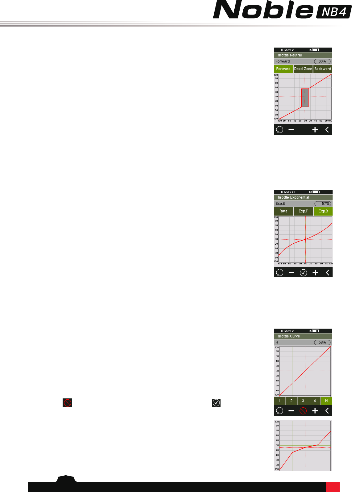
Throttle Neutral creates a congurable dead zone for the throttle channel.
Forward: How far the dead zone extends into the throttle zone.
Dead Zone: The point at which the channel will kick in when the trigger passes the
threshold.
Backward: How far the dead zone extends into the braking zone.
6.7ThrottleNeutral
6.8ThrottleExponential
Setup:
1. Touch "Forward", "Dead Zone" or "Backward" to select it.
2. Use the + and - icons to to change the percentage as needed.
3. Repeat with other settings as needed.
4. Test to make sure everything works as expected.
This function changes the throttle channel's response curve. There are 2 main
parameters:
• Rate: Changes the outer limits of the steering, the default and maximum is
100%.
• Exp. (Exponential): Changes thesteeringcurve, which changes the response
of the throttle. The Exp. setting can be positive or negative.
Changes to the rate and exponential can be seen on the graph located in the center of
the screen. The system also gives a real-time readout of the channel's current position.
Setup:
1. Touch rate or EXP.
2. Use the + and - icons to raise or lower the percentage as needed.
3. Repeat for the other setting as needed.
4. Test to make sure everything is working as expected.
6.9ThrottleCurve
This function changes the shape of the thottles response curve. There are 2 main
parameters:
There are 5 editible points, L, 1, 2, 3, 4 and H. As the line is edited the throttle will then
follow the new curve value as the throttle moves alone the x axis of the graph.
Setup:
1. Touch the icon to enable the function. The icon will change to when enabled.
2. Touch a point.
3. Use the + and - icons to raise or lower the points position as needed.
4. Repeat for the other points as needed.
5. Test to make sure everything is working as expected.
13
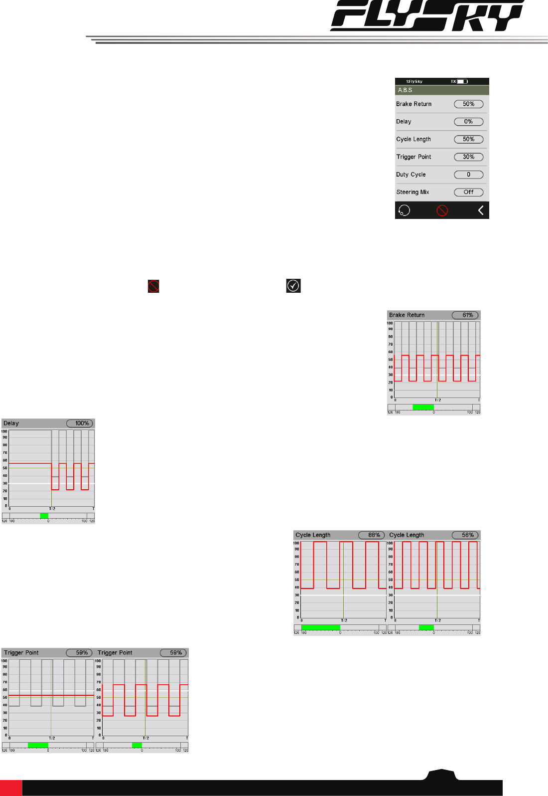
6.10A.B.S.
A.B.S. stands for auto breaking system. This function is used to stop the wheels from
locking which can lead to loss of control or a skid. A.B.S. manages this by regulating the
amount of pressure the breaks use, which is done by pumping the breaks on and off
rather than a constant force.
There are six sub menus for A.B.S. function setting, [Brake return], [Delay], [Cycle
length], [Trigger point], [Duty cycle], and [Steering mix].
In the submenus, pulses are shown as a square wave, the peaks indicating brake on,
and troughs in-dicating reduction in braking. As the value changes, the square wave will
change to represent the function's current
settings.
The trigger point is represented as a white line on the graph.
Below the graph is a bar that shows the real-time braking position. When this function is
active and the brake is applied, the green bar will oscillate in real time showing the A.B.S.
in action.
BreakReturn
Controls the reduction of braking during each pulse. If set to 60%, when the
brakes are active; the system will remove 60% of the brakes strength on each pulse.
Delay
Determines how long it takes for the A.B.S. system to take eect. At a setting of 0%, the
A.B.S. system will take eect as soon as the brake is applied. The higher the value, the
longer it will take for the A.B.S. to function.
CycleLength
Increases or decreases the time between pulses. The higher the
value, the longer the pulse.
TriggerPoint
Configures the point at which the A.B.S. starts to function. The
higher the percentage, the further the trigger has to be moved to
activate the A.B.S.
To activate this function press the icon. The icon will change to when active.
14
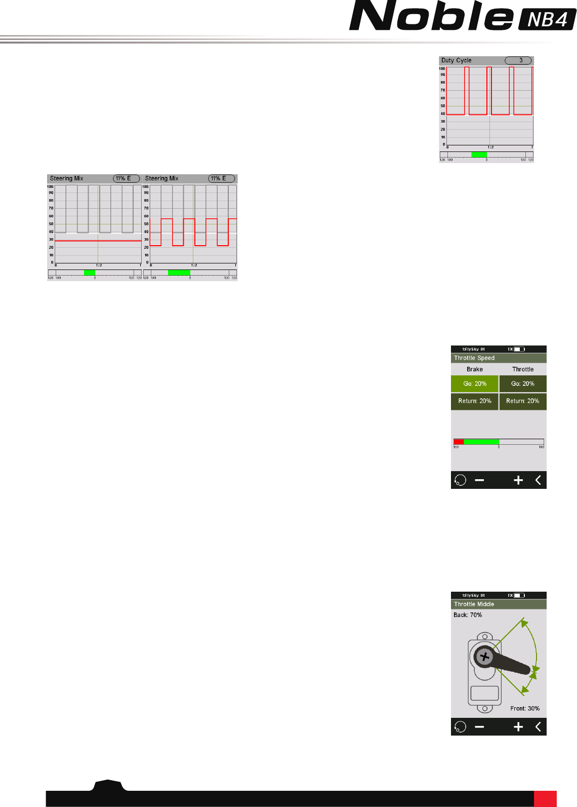
DutyCycle
Changes the length of each pulse and the gap between them. As the value changes,
the length of the braking waves peaks and troughs will change independently of each
other and will no longer be symmetrical.
SteeringMix
A.B.S. can be reduced automatically while turning. This function
mixes braking and steering to turn reduce the A.B.S. or replace it
with a constant braking pressure.v
6.11ThrottleSpeed
Throttle Speed changes how quickly the throttle will react, for both braking and throttle.
There are 2 settings for brake and throttle:
• Go: Sets how quickly the throttle applies acceleration.
• Return: Sets how quickly the throttle backs o.
The lower the percentage the longer it will take for the throttle to catch up
with the trigger movement.
The bar in the middle of the screen will show the throttle's current position
in real time. The red bar is the triggers current position; the green bar is the channels
current posi-tion.
Setup:
1. Select the desired setting, [Go] or [Return].
2. Use the + or - icons to change the percentage.
3. Repeat with the other settings as needed.
4. Test to make sure everything works as expected.
6.12ThrottleMiddle
This function changes the midpoint of the throttle, and could be used to
correct the servo position. If the servo position is wrong, the model may
move as soon as it's turned on.
Setup:
1. Use the + and - keys to change the throttle middle position.
2. Test to make sure everything is working as expected.
15
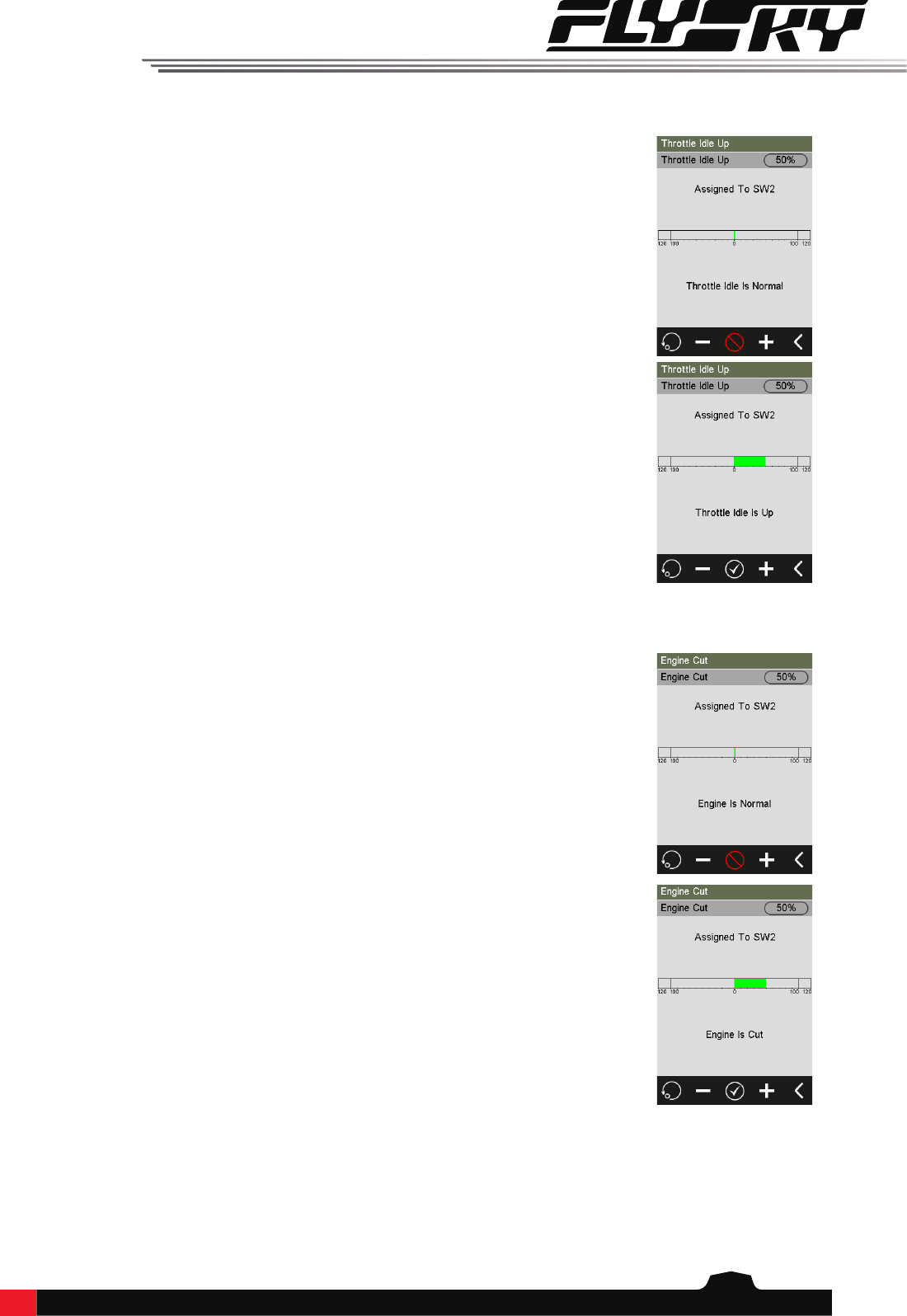
6.13ThrottleIdleUp
Throttle Idle Up is used for models that use a fuel based engine that will stall
if left at 0 throttle. Idle up makes sure that the engine always has some
throttle in order to keep it from stalling.
This function must be assigned to a switch/button in order to be activated
(See [Buttons Assign]). If not, the function cannot be activated.
Setup:
1. Assign the Throttle Idle Up function to a button. For more information on this see the
[Buttons Assign] section of this user manual. Now when the button is press it will toggle
Throttle Idle Up on and o.
2. Use the + and - icons to change the percentage.
3. Test to make sure everything works as expected.
6.14EngineCut
When Engine Cut is triggered via a button it sets the throttle channel to a predefined
position.
This function must be assigned to a switch/button in order to be activated
(See [Buttons Assign]). If not, the function cannot be activated.
Setup:
1. Assign the Engine Cut function to a button. For more information on this see the
[Buttons Assign] section of this user manual. Now when the button is press it will toggle
Engine Cut on and o.
2. Use the + and - icons to change the percentage.
3. Test to make sure everything works as expected.
16
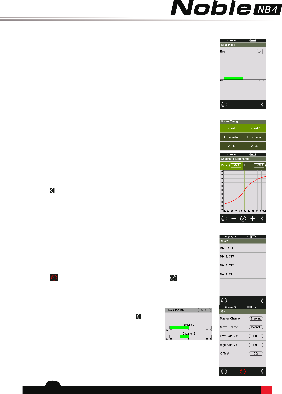
6.15BoatMode
6.16BrakeMixing
This function is used only when you are using a model boat. When this function is active,
the throttle channel is set to its lowest position and the brake functionality is disabled.
To toggle this function, select the box beside [Normal mode]. When the function is
active, the text beside the box will change to [Boat mode].
This function enables you to use models that require more than one
braking channel, for example a model that has separate brakes for front
and back braking.
If your model uses extra channels for braking, each channel can be controlled separately
and are slaves of the throttle channel.
Setup:
1. Touch channel 3 or 4 to reveal that channels options.
2. Touch the exponential option to enter the exponential settings.
3. Touch rate and use the + and - iconds to change the percentage and do the same for
Exp.
4. Touch the icon to return to the brake mixing main menu.
5. Touch A.B.S. to enter the sub menu.
6. Refere to the [A.B.S.] section of the user manual for more information on how to set
up A.B.S.
7. Use the Display Servos function to make sure everything is working as expected.
6.17Mixes
Mixes is used to create a mix between channels.
Setup:
1. Touch a mix to select it.
2. Touch the icon to enable the function. The icon will change to when enabled.
3. Touch "Master Channel", then select a master channel from the list.
4. Touch "Slave Channel", then select a slave channel from the list.
6. Repeat step 5 for the other mix as needed.
7. Touch oset, then use the + and - icons to change the slave channels oset relative to
the master.
5. Select [Low side mix] or [High side mix] as needed. Use the +
and - icons to change the mix percentage. Press the icon when
nished to return to the mix menu.
17
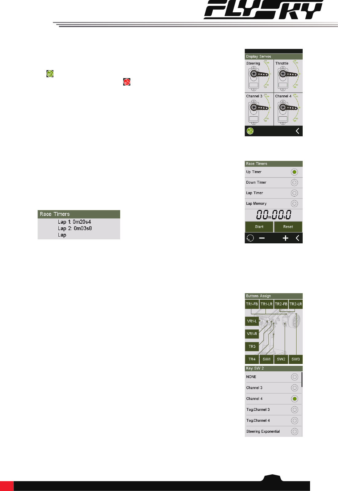
6.18DisplayServos
This function displays the model's channel output and can be used to test
output and servo range.
Press the icon to start servo test mode, which will move all the channels slowly
though their entire range of motion. Press the icon to turn o servo test mode.
WARNING:
Make sure the model engine is powered o while the test function is activated.
6.19RaceTimers
Modes:
• Up Timer: Counts up.
• Down Timer: Counts down from the set time. Use the + and - icons to set a
time to count down from.
• Lap Timer: Keeps track time for each individual lap.
• Lap Memory: Records the results from the lap timer.
Setup:
Touch "Start" to start the timer, "Stop" to stop.
6.20ButtonsAssign
This function assigns the system's physical buttons to different functions for quick
control.
Setup:
1. Touch a switch, button, wheel or trim from the diagram.
2. Select a function from the list.

18
6.21Models
This function is used to change, reset, rename or copy model setups. The NB4 can store
up to 20 dierent models in the internal memory.
Selecting a model: To select a model touch "Select Model", then touch a model from the
list.
Naming a model: To rename a model touch "Name:", then use the on screen keyboard
to enter a new name. Press the icon when nished to return to save and return to the
previous menu.
Copying a model: Touch "Copy Model", then touch the model to copy from the list. Next
select a target slot from the list, this will overwrite everything in that slot. The system
will ask if you are sure, select yes.
Reseting a model: To reset a model touch "Model" reset, then select the model you wish
to reset from the list. The system will ask if you are sure, select yes.
19
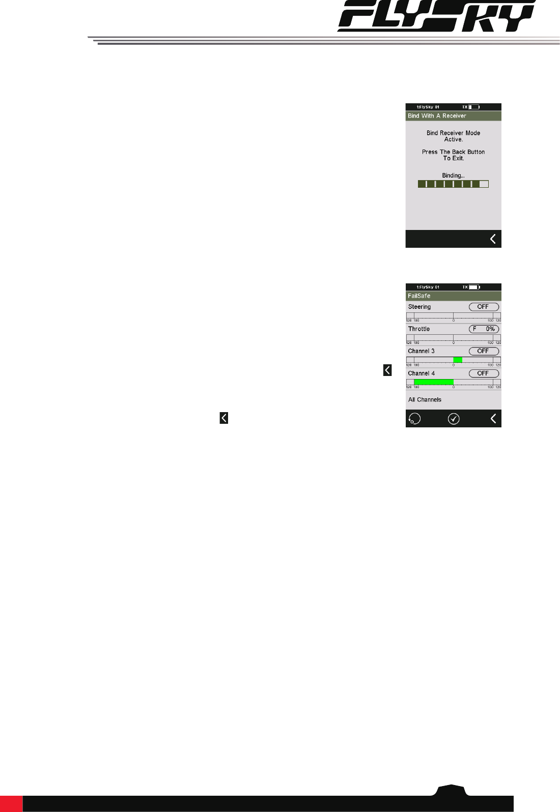
This function is used to protect the models and users if the receiver loses signal and
therefore is no longer controllable.
Setup:
1. Select a channel by touching the box to the right of the channel name. The box will be
highlighted in green when selected.
2. Move the channel to the desired location, hold it in that position, then press the
icon.
To set all channels at the same time, touch "All Channels", move all the channels and
hold them in the desired location, then press the icon to save.
7RXSetup
7.1BindWithAReceiver
To bind with a reciever:
1. Put the receiver into bind mode (Check the receiver's user manual for your receiver on
how to enter bind mode).
2. Touch "Bind With A Receiver" in the RX Setup menu. The NB4 will now bind with the
receiver and exit automatically when binding is complete.
7.2Failsafe
20
8System
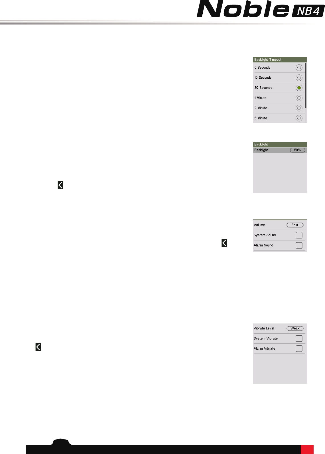
8.1BacklightTimeout
The backlight timeout function controls how long the system will wait before turning o
screens backlight.
Setup:
1. Select a time from the list.
8.2Backlight
8.3Sound
8.4Vibration
This function controls the backlight brightness.
Setup:
1. Use the + and - icons to change the backlight percentage.
2. Touch the icon to save and return to the previous menu.
This function is used to toggle all system sounds, including power-on/power-o sounds,
key sounds and so on.
Volume: Touch volume then select the desired volume from the list. Touch the icon to
return to the previous menu.
System Sound: Toggle system sounds by touching the box to the right of "System
sound". If there is a check in the box it is enabled.
Alarm Sound: To turn o alarms and allerts touch the box to the right of "Alarm sound".
If there is a check in the box it is enabled.
Vibration sets the various vibration functions available for the system.
Vibrate Level: Touch "Vibrate Level" then select the desired strength from the list. Touch
the icon to return to the previous menu.
System Sound: Toggle system sounds by touching the box to the right of "System
sound". If there is a check in the box it is enabled.
Alarm Sound: To turn o alarms and allerts touch the box to the right of "Alarm sound".
If there is a check in the box it is enabled.
21
8.5LED
8.6Language
8.7AutoPowerO
8.8RadioFrequencySetup
8.9StickCalibration
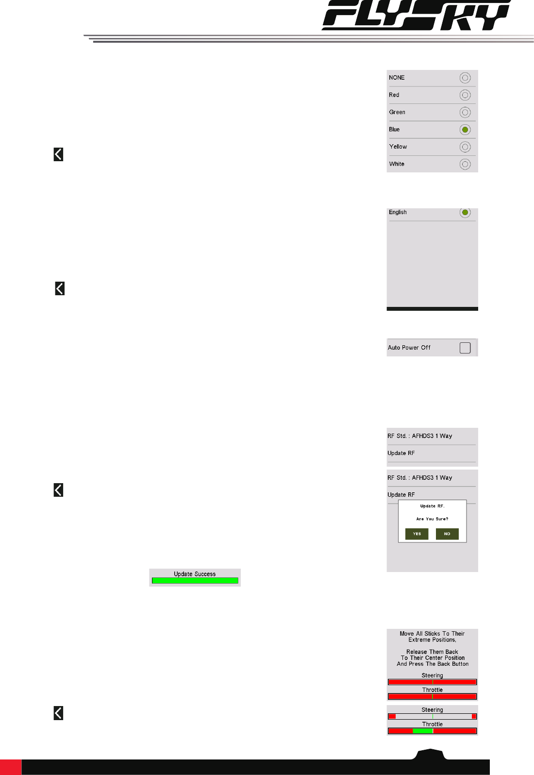
LED Light changes the color of the LED strip located above the power button.
Changing Color:
1. Touch LED Light to enter the menu.
2. Select a color from the list.
3. Touch the icon to return to the previous menu.
Language changes the language for the user interface.
Changing Language:
1. Touch "Language" to enter the menu.
2. Select a language from the list.
3. Touch the icon to return to the previous menu.
Auto Power O will turn o the transmitter if no receiver is connected and the user has
not done anything for 2 minutes.
To toggle Auto Power O touch the box to the right of the setting. If there is a check in
the box the function is active.
Radio Frequency Setup contains the RF protocol settings for the transmitter and receiver.
Change RF Protocol:
1. Touch "RF Std. :" and select a protocol from the list.
2. Touch the icon to return to the previous menu.
Update RF:
Update RF updates the internal RF module. The update will be contained within a
rmware update for the NB4. To update touch "Update RF", a progress bar will appear
and after a few seconds the update will complete.
Stick Calibration calibrates the trigger and wheel so that their center and outer positions
are correct. The green bar is the channels current position and the calibrated range will
be grey like the background.
Calibration:
1. Move the wheel and trigger as far as they can go in each direction.
2. Touch the icon to save and return to the previous menu.
22
8.10FirmwareUpdate
8.11FactoryReset
8.12AboutNoble
The internal software of the transmitter can be updated using the USB interface
connected via a windows computer. Once this function is activated, all functions of the
transmitter stop. To avoid any loss of control of the vehicle, turn its receiver o before
entering this mode.
When the rmware is updating, never disconnect the USB cable or remove the battery or
the transmitter.
1. Download and open the newest ocial software.
2. Connect a transmitter with a computer by USB cable.
3. Touch "Firmware Update", then touch "Yes".
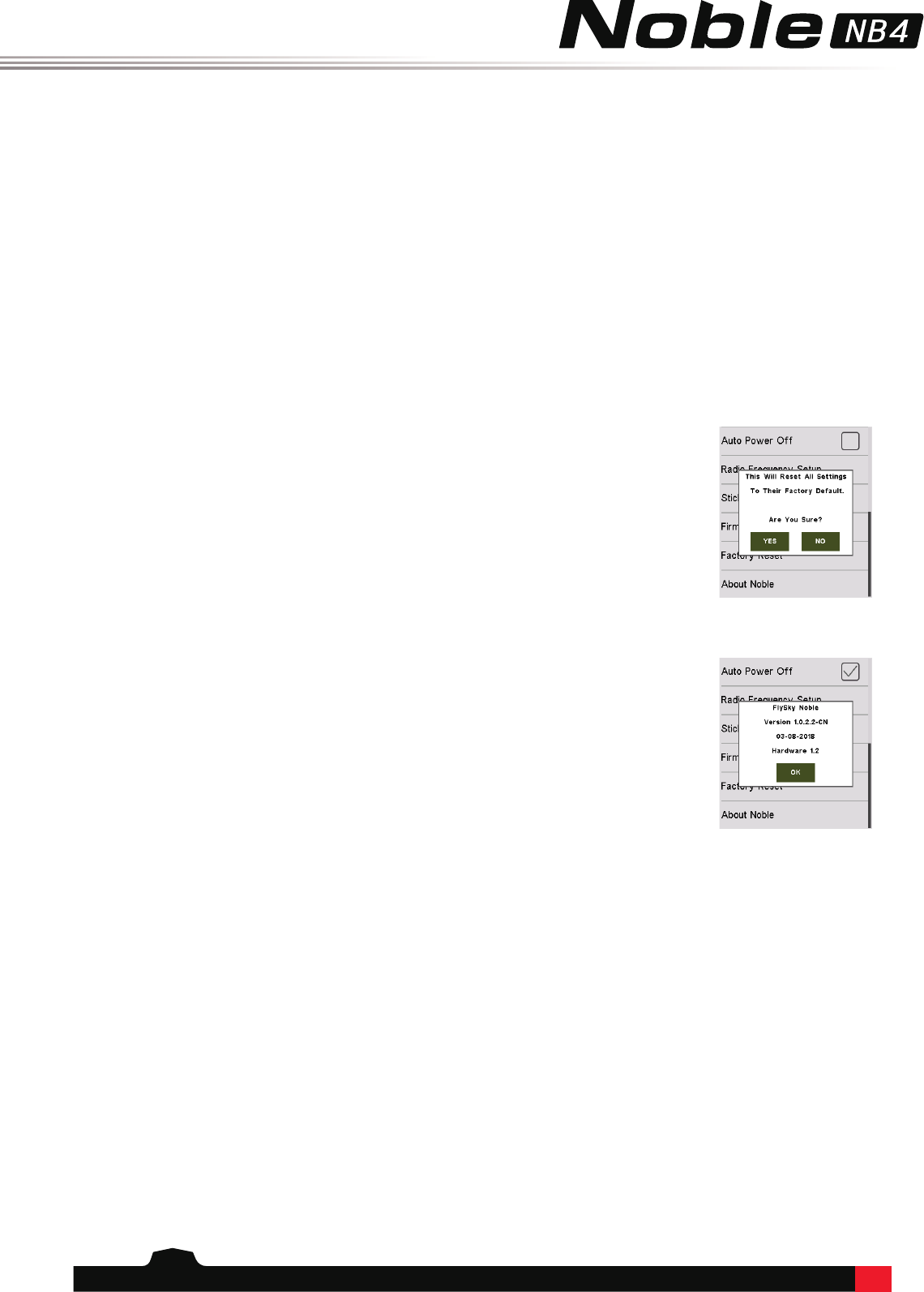
Factory Reset resets all of the transmitter settings and functions back to their factory
default state.
Reset:
Touch "Factory Reset", then touch "YES" when prompted.
Contains basic information including product name, rmware version, actavation date
and hardware version.
23
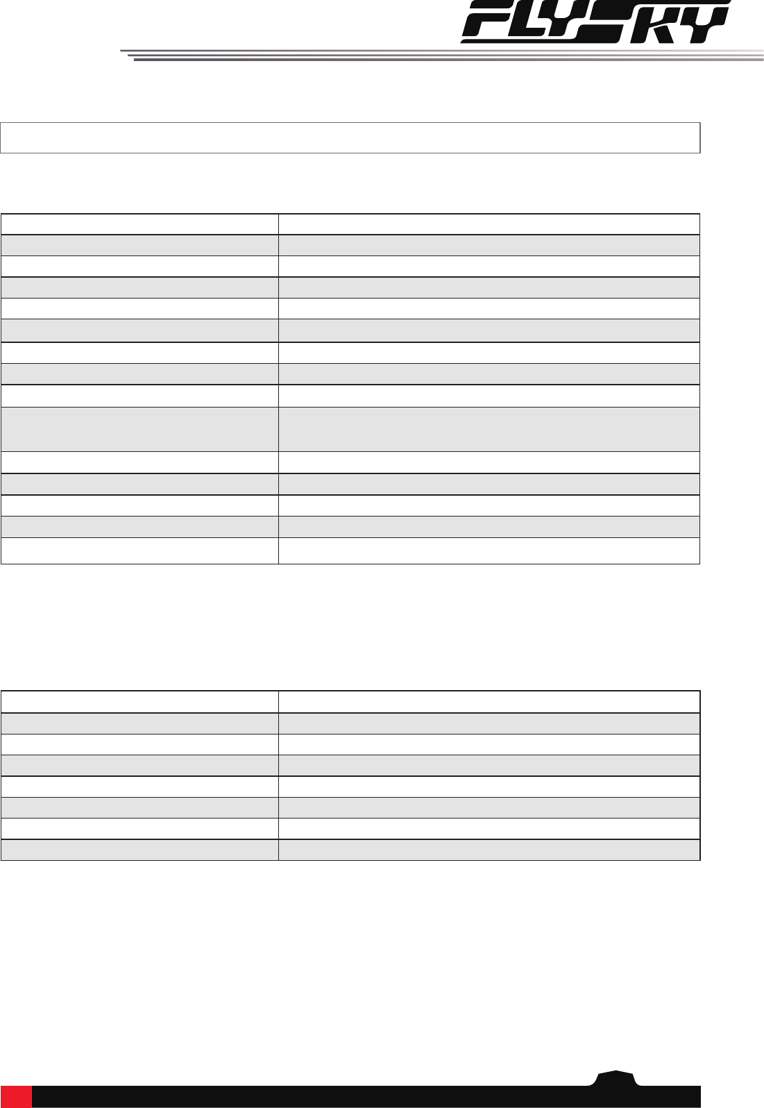
9.ProductSpecications
This section contains NB4 transmitter and FGr4 receiver specications.
9.1Transmitterspecication(NB4)
7.2ReceiverSpecication(FGr4)
Model Type Car, Boat
Channels 4
RF Range 2.402-2.480GHz
RF Power <20dBm (EU)
2.4GHz Protocol AFHDS 3
Data Output Micro USB
Charging Port Micro USB
Antenna Type Built-in Single Antenna
Input Power 1S/4.2V Lithium Polymer Battery
Screen HVGA 3.5 inch TFT color screen with a resolution of 320*480,
LCD white backlight, capacitive touch screen
Online Update Yes
Range (Ground no interference) > 300m
Dimensions 129*114*190 mm
Weight 520g
Certication CE, FCC ID:N4ZFG400
Channels 4
RF range 2.402-2.480 GHz
RF Standard AFHDS 3
RF Power <20dBm (EU)
Power input 3.5V-18V
Weight 15g
Dimensions 46 * 28 * 22 mm
Certicate CE, FCC ID:N4ZFGR400

24
10.PackageContents
NB4 Transmitter x 1
FGr4 x 1
Quick Start Quide x 1
USB Wire x 1
Hand Grip L x 1
Bluetooth module x 1 (optional)
Ibus Module x 1 (optional)

25
11.Certication
Hereby, [Flysky Technology co., ltd] declares that the Radio Equipment [FG4] is in compliance with RED 2014/53/EU.
The full text of the EU DoC is available at the following internet address: www.ysky-cn.com
11.1DoCDeclaration
11.2CEWarning
The antenna(s) used for this transmitter must be installed to provide a separation distance of at least 20 cm from all
persons and must not be co-located or operating in conjunction with any other transmitter. End-users and installers
must be provided with antenna installation instructions and transmitter operating conditions for satisfying RF
exposure compliance
11.3Environmentallyfriendlydisposal
Old electrical appliances must not be disposed of together with the
residual waste, but have to be disposed of separately. The disposal at the
communal collecting point via private persons is for free. The owner of old
appliances is responsible to bring the appliances to these collecting points
or to similar collection points. With this little personal eort, you contribute
to recycle valuable raw materials and the treatment of toxic substances.
CAUTION
RISK OF EXPLOSION IF BATTERY IS REPLACED BY AN INCORRECT TYPE.
DISPOSE OF USED BATTERIES ACCORDING TO THE INSTRUCTIONS

26
This equipment has been tested and found to comply with the limits for a Class B digital device pursuant to part
15 of the FCC rules. These limits are designed to provide reasonable protection against harmful interference in a
residential installation. This equipment generates, uses and can radiate radio frequency energy and, if not installed
and used in accordance with the instructions, may cause harmful interference to radio communications. However,
there is no guarantee that interference will not occur in a particular installation. If this equipment does cause
harmful interference to radio or televison reception, which can be determined by turning the equipment o and on,
the user is encouraged to try to correct the interference by one or more of the following measures:
Reorient or relocate the receiving antenna.
Increase the separation between the equipment and receiver.
Connect the equipment into an outlet on a circuit dierent from that to which the receiver is connected.
Consult the dealer or an experienced radio/TV technician for help.
To assure continued compliance, any changes or modications not expressly approved by the party responsible for
compliance could void the user’s authority to operate this equipment.
This equipment complies with Part 15 of the FCC Rules. Operation is subject to the following two conditions:
(1) This device may not cause harmful interference, and
(2) This device must accept any interference received, including interference that may cause undesired operation.
Caution!
The manufacturer is not responsible for any radio or TV interference caused by unauthorized modications to this
equipment. Such modications could void the user authority to operate the equipment.
1. Move all your channels to the desired position.
2. Select [All channels] and then [Yes] in the conrmation box.
11.4Appendix1FCCStatement

www.ysky-cn.com
Copyright ©2018 Flysky Technology co., ltd
Release date: 2018-09-20
FCC ID: N4ZFG400