FLYSKY RC MODEL TECHNOLOGY FLYSKYIA6B 2.4 GHz 6 CHANNELS RECEIVER User Manual 1
FLYSKY RC MODEL TECHNOLOGY CO., LTD 2.4 GHz 6 CHANNELS RECEIVER 1
User Manual
Digitalproportionalradiocontrolsystem
SER VOSEN S
CH5
CH6
B/VCC
CH2
CH3
CH4
PPM/C H1
i-B US
A
LED UPDATE
FS-I A6B
6 CHAN NELS RE CEI VER
2.4
GHz
4.0- 6.5V/D C
B
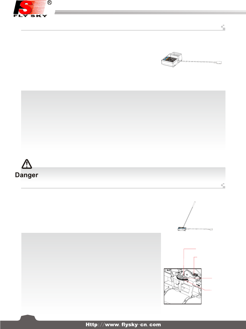
FS-iA6B Receiver FS-iA6B接收机
FS-iA6B Receiver Specification FS-iA6B接收机参数
FS-IA6B接收机与伺服器连接 Receiver and servo connections
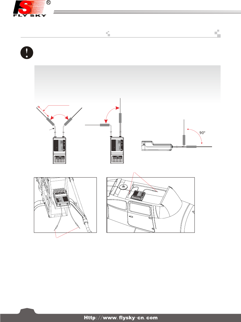
为了让发射及接收距离更远,请注意以下几点:
1、尽量保证双天线笔直,否则将会减小控制范围;
2、双天线的夹角保持在90°(如图三种方式),这并不是精确的垂直角度,重要的是尽可能保持天线互相远离;
3、天线应该尽可能远离金属导体,至少要有l.5cm左右的距离。轴电缆段不受此限制,但不要过度弯曲;
4、尽可能保持天线远离电动机、调速器,和其它的噪声源。
接收机
Receiver
( Pic 11.1 ) ( Pic 11.2 )
In order to make sure maximum distance between the transmitter and receive can be obtained please follow the
directions below:
1. The two antennas must be kept as straight as possible. Otherwise, control range will be reduced.
2. The two antennas should be placed at a 90 degree angle to each other, as illustrated in the three pictures below.
3. The antennas must be kept away from conductive materials, such as metal and carbon. A distance of at least 15 cm
is required for safe operation. Conductive materials will not affect the coaxial part of the antenna, but it is important
that the coaxials are not bent to a severe radius.
4. Keep antennas away from the motor, speed controller and other noise souces as much as possible.
天线(26mm)
同轴电缆
90° 90°
接收机
Receiver
( Pic 11.3 )
接收机
Receiver
Coaxial cable
天线
天线 Antenna
Antenna
SER VOSEN S
CH5
CH6
B/VCC
CH2
CH3
CH4
PPM/C H1
i-B US
A
LED UPDATE
FS-IA6B
6 CHA NNELS R ECEI VE R
2.4
GHz
4.0 -6.5V/DC
SER VOSEN S
CH5
CH6
B/VCC
CH2
CH3
CH4
PPM/C H1
i-B US
A
LED UPDATE
FS-IA6B
6 CHA NNELS R ECEI VE R
2.4
GHz
4.0 -6.5V/DC
SERVOSENS
CH5
CH6
B/VCC
CH2
CH3
CH4
PPM/CH1
i-BUS
A
LED UPDATE
FS-IA6B
6 CHANNELS RECEI VER
2.4
GHz
4.0-6.5V/DC
SERVOSENS
CH5
CH6
B/VCC
CH2
CH3
CH4
PPM/CH1
i-BUS
A
LED UPDATE
FS-IA6B
6 CHANNELS RECEI VER
2.4
GHz
4.0-6.5V/DC
2
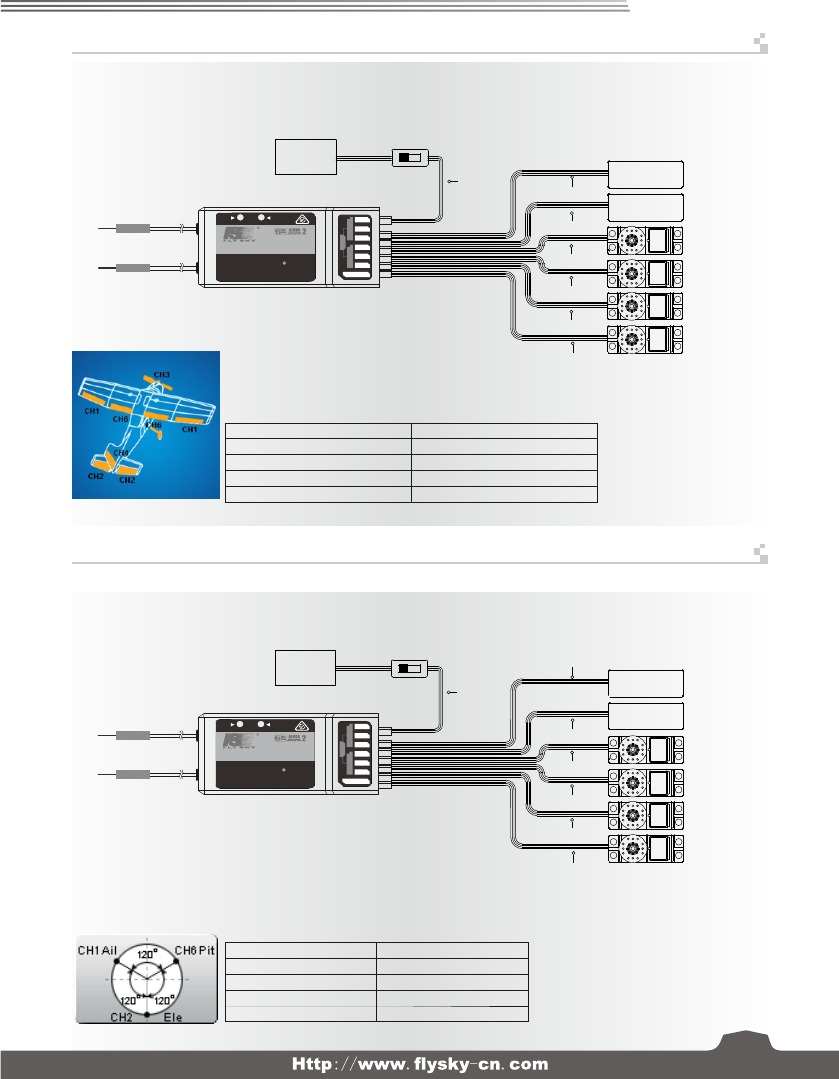
直升机模型的安装 Helicopter model installation
CH1
CH2
CH3
CH4
CH5
CH6
Gyroscope陀螺仪
Pitch 螺距
油门舵机
Throttle servo
方向舵机
Rudder servo
副翼舵机
Aileron servo
升降舵机
Elevator servo
接收机 Receiver
接收机和直升机的连接方法,例如:
结构:可变螺距(120度)+陀螺仪
Ch1:副翼Aileron Ch2:升降Elevator
Ch3:油门Throttle Ch4:方向Rudder
Ch5:陀螺仪Gyroscope Ch6:螺距Pitch
Receiver and helicopter connections, for example:
Structure: variable pitch(120 degrees)+governor
飞机模型的安装 Airplane model installa tion
接收机 Receiver
B/V
Aux.1起落架
Aux.2襟翼
CH1
CH2
CH3
CH4
CH5
CH6
油门舵机
Throttle servo
方向舵机
Rudder servo
副翼舵机
Alieron servo
升降舵机
Elevator servo
开关 Switch
电池
接收机和固定翼的连接方法,例如:
结构:副翼+襟翼+起落架
Ch1:副翼Aileron Ch2:升降Elevator
Ch3:油门Throttle Ch4:方向Rudder
Ch5:起落架 Ch6:襟翼Flap
Connection method for the receiver and
the fix wing, for example:
Structure: Two ailerons+flap+The landing gear
Battery
B/V
开关
电池 Battery
Switch
A
LED U PDATE
FS-IA6B
6 CHANNELS RECEI VER
2.4
GHz
4.0-6.5V/DC
SERVOSENS
CH5
CH6
B/V CC
CH2
CH3
CH4
PPM /CH1
i-BUS
A
LED U PDATE
FS-IA6B
6 CHANNELS RECEI VER
2.4
GHz
4.0-6.5V/DC
SERVOSENS
CH5
CH6
B/V CC
CH2
CH3
CH4
PPM /CH1
i-BUS
Digitalproportionalradiocontrolsystem
3
CH5
The landing gear
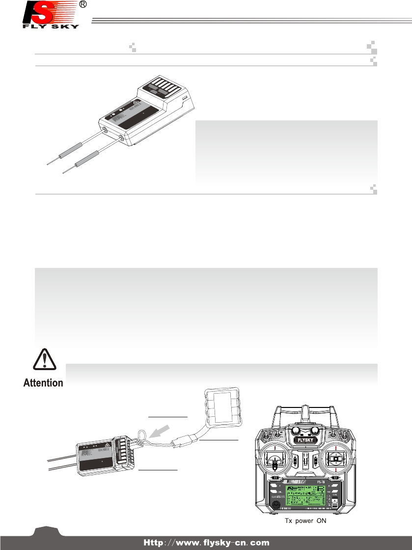
接收机操作说明 Receiver operation instruction
对码线
Bind cable
接收机
Receiver
电池
Battery
14
对码 Binding Setup
接口说明 Port Setup
所有的发射机和接收机,在出厂前都已对码,无需再次对码,若您需要与另一发射机进行对码和使用,
请按以下方法操作:
1. 发射机装上电池,打开电源;
2. 进入主界面,选择接收机设置功能。点触对码进入对码状态;
3. 用产品包装所配的对码线,插入接收机B/VCC通道;
4. 使用4.0-6.5VDC电源,按正确极性,插入CH1- CH6的任一通道,即可进入对码状态,此时LED灯闪烁;
5. 成功对码后,发射机会自动退出对码状态;
6. 拔掉对码线,重启接收机LED常亮,此时即可插入舵机及其它数据采集模块,检测其工作是否正常;
7. 如果对码失败,可重复以上动作,重新对码。
(Pic 12.1)
(Pic 12.2)
CH1-CH6: 表示接收机的相应通道;
Bind,VCC: 表示用于对码和输入电源的通道;
OUT:表示输出PPM数据的i-BUS接口,用于连接串行总线接收
机,扩展通道;
IN:表示各种传感器数据的输入接口,数据采集模块可随意串接;
CH1/PPM: 表示CH1输出通道兼有PPM信号输出功能
CH1-CH6: represent relevant channel of transmitter.
Bind,VCC: represent the channel used for matching and input
power respectively.
OUT: Represent i-BUS port of outputting PPMS data and be used
for connecting the serial bus receiver to expand channels.
IN: Represent input ports of all kinds of sensor data, and data
acquisition modules can be connected in serial optionally.
All receivers are bound to their respective transmitter at production time. If you want to bind it with another transmitter,
please follow the steps below:
1. Install the battery in the transmitter, and turn on the power.
2. Open the main menu, and select "RX setup" function in the second page, then touch "Bind with a receiver" to enter bind mode.
3. Insert the standard bind cable into the power supply channel.
4. Connect the 6VDC power connector to any channel from CH1 to CH 6 with correct polarity to enter bind mode, The receiver
LED will flash at this time.
5. The transmitter will exit the bind mode automatically after having successfully bound with the transmitter.
6. Pull off the bind cable and restart the receiver. Please connect the servos and other telemetry modules to the receiver to check
if everything operates normally.
7. If anything is wrong, please repeat the above steps to bind again.
注意:配对好的发射机与接收机,当发射机或接收机因误操作而进入对码状态后, 会出现不能遥控的现象,
一般情况下,关闭电源重开机即可恢复正常,倘若还是不行,则需要重新对码。
Notice: The bound transmitter and receiver will work abnormally if the transmitter or the receiver enters the binding state
by mistake. In other words, the receiver cannot be controlled by the transmitter. If so, you need to restart the transmitter
and the receiver.
515
CH1/PPM: output of channel 1 or PPM output.
(Please see the RX setup)
SERVOSENS
CH5
CH6
B/V CC
CH2
CH3
CH4
PPM /CH1
i-BUS
A
LED U PDATE
FS-IA6B
6 CHANNELS RECEI VER
2.4
GHz
4.0 -6.5V/DC
4
SERV O
SENS
CH5
CH6
B/V CC
CH2
CH3
CH4
PPM /CH1
i-BU S
A
LED UP DATE
FS-IA6B
6 CHA NNELS RECEI VER
2.4
GHz
4.0 -6.5 V/DC
LED
FS-SPD01
SPEED
2
OUT
IN
Magnetic
15
FS-CEV04 i-BUS 串行总线接收机连接说明
FS-CPD01 磁感应转速采集模块 RPM telemetry (magnetic) module setup
传感器 Sensor
速度采集模块
Revolving
speed module
齿轮
Gear
磁铁
Magnet
串行总线接收机,最多可串联4个模块,共16个通道;按键K1-K4分别对应C1-C4, 用于对相应通道的设定;
操作说明:
1. FS-CEV04 i-BUS接收机的“IN”端口对应接收机的“OUT”端口;
2. FS-CEV04 i-BUS接收机的“OUT”端口,用于串接后级的FS-CEV04接收机,以串联的 方式使用。
3. 将此总线接收机插入接收机,打开己配对的发射机,接收机电源,LED点亮;
4. 操作发射机触控屏,选择接收机设定的主菜单,进入到舵机设定界面;
5. 选择需要扩展的通道,此时,总线接收机的LED熄灭;
6. 用对码线上的胶针,按下需要的,相应通道的按键,LED自动点亮,表示设定成功;
7. 插入舵机,检查设定是否成功;
8. 重复以上操作即可完成总线接收机4个通道的设定;
9. 当需要更多的通道扩展时,只需要在第一级总线接收机的“OUT”端口,串接新的总线接收机即可,设定的操作方法相同。
注意: 当总线接收机的负载过重,电流较大时,请将主接收机的电源分支出来并联接入,单独供电加大负载的能力,
否则可能会因电流过大,烧坏串联的线材。
操作使用说明:
1. 将所配的3 PIN插头,一端插入速度采集模块的“OUT”位置,另一端插入接收机的“IN”位置或
接另外的感应器的“IN”位置,如图12.4所示;
2. 如图12.5所示,将传感器放在磁铁的旁边,磁铁固定在需要测试的轴向转动的地方,如直升机的
齿 轮上面,传感器与磁铁相距两毫米以内,磁铁的南极或北极与传感器保持平行。
3. 打开发射机,接收机电源,在显示屏的接收机窗口内,会发现并显示“Motor speed 2:0RPM”,
试着转动,转速的值会发生变化,则表示安装成功。
(Pic 12.3)
(Pic 12.4)
(Pic 12.5)
i-BUS receiver, can connect 4 modules with 16 channels in serial at most. Button K1 and K4 correspond to C1 and C4
respectively.
Operation instruction:
1. FS-CEV04 i-BUS The “IN” port of FS-CEV04 receiver corresponds to “OUT” port of receiver.
2. FS-CEV04 i-BUS The “OUT” port of FS-CEV04 receiver is used to connect post level
FS-CEV04 receiver.
3. Insert the bus receiver to receiver, and then switch on the matched transmitter and receiver. The LED will be on.
4. Select main menu of receiver setup to enter the interface of servo setup.
5. Select channel which need to be expanded, meanwhile LED of bus receiver is off.
6. Push relevant channel button by plastic needle of matching line. The setup is successful if LED flashes automatically.
7. Insert servo to check.
8. Set up 4 channels of bus receiver as above steps.
9. Just connect a new bus receiver with “OUT” port of first stage bus receiver if more channel needed. Set up the new one as
above steps.
Notice: When the load of serial bus receiver is excessive and electric current is higher than usual, please supply power
directly to the serial bus receiver or it will break cables.
Operation:
1. Insert one end of standard 3 PIN plug into “OUT” port of RPM telemetry (magnetic)
module, and insert the other end into “IN” port of receiver or other sensor, as shown
in the picture 12.4.
2. As shown in the picture 12.5: Inside hub of the model, the distance between sensor
and magnet is less than2mm. The North Pole or the south pole of the magnet has
to be paralleled with sensor.
3. Switch on transmitter and receiver. “Motor speed 2:0RPM” will be shown in receiver
window in display screen. Speed value changes as turning wheel, which means
installation is successful.
功能说明:
此功能是为了应对某些模型通道太多而做的,当通道不够时可采用此配件,来增加通道输出。
功能说明:
此功能是为了检测到模型的转速而设定的,用户可通过发射机来观察监测模 型的转速,当用户需要监测转速时可使用此配件。
The system is able to support many channels. This allows the user of the system to change to a different
output channel should signal strength be insufficient
This function allows the user to monitor turning speed via the transmitter. This is a
very useful function when determination of turning speed is required
Function Details:
Function Details:
i-bus Receive r Connection instruc tion Setup
5
FCC Statement
This equipment has been tested and found to comply with the limits for a
Class B digital device, pursuant to Part 15 of the FCC Rules. These limits
are designed to provide reasonable protection against harmful
interference in a residential installation. This equipment generates uses
and can radiate radio frequency energy and, if not installed and used in
accordance with the instructions, may cause harmful interference to radio
communications. However, there is no guarantee that interference will
not occur in a particular installation. If this equipment does cause harmful
interference to radio or television reception, which can be determined by
turning the equipment off and on, the user is encouraged to try to correct
the interference by one or more of the following measures:
-- Reorient or relocate the receiving antenna.
-- Increase the separation between the equipment and receiver.
-- Connect the equipment into an outlet on a circuit different from that to
which the receiver is connected.
-- Consult the dealer or an experienced radio/TV technician for help.
This device complies with part 15 of the FCC Rules. Operation is subject
to the following two conditions:
(1) This device may not cause harmful interference, and (2) this device
must accept any interference received, including interference that may
cause undesired operation.
Changes or modifications not expressly approved by the party responsible
for compliance could void the user's authority to operate the equipment.
The antenna(s) used for this transmitter must be installed to provide a
separation distance of at least 20 cm from all persons and must not be co-
located or operating in conjunction with any other antenna or transmitter.