FLYSKY RC MODEL TECHNOLOGY FLYSKYIT4S 2.4G AFHDS 2A system User Manual
FLYSKY RC MODEL TECHNOLOGY CO., LTD 2.4G AFHDS 2A system
UserManual.wiki
>
FLYSKY RC MODEL TECHNOLOGY
>
FLYSKYIT4S User Manual
User Manual
Navigation menu
Upload a User Manual
Namespaces
Wiki Guide
HTML
PDF
Info
Views
User Manual
Discussion / Help
Navigation
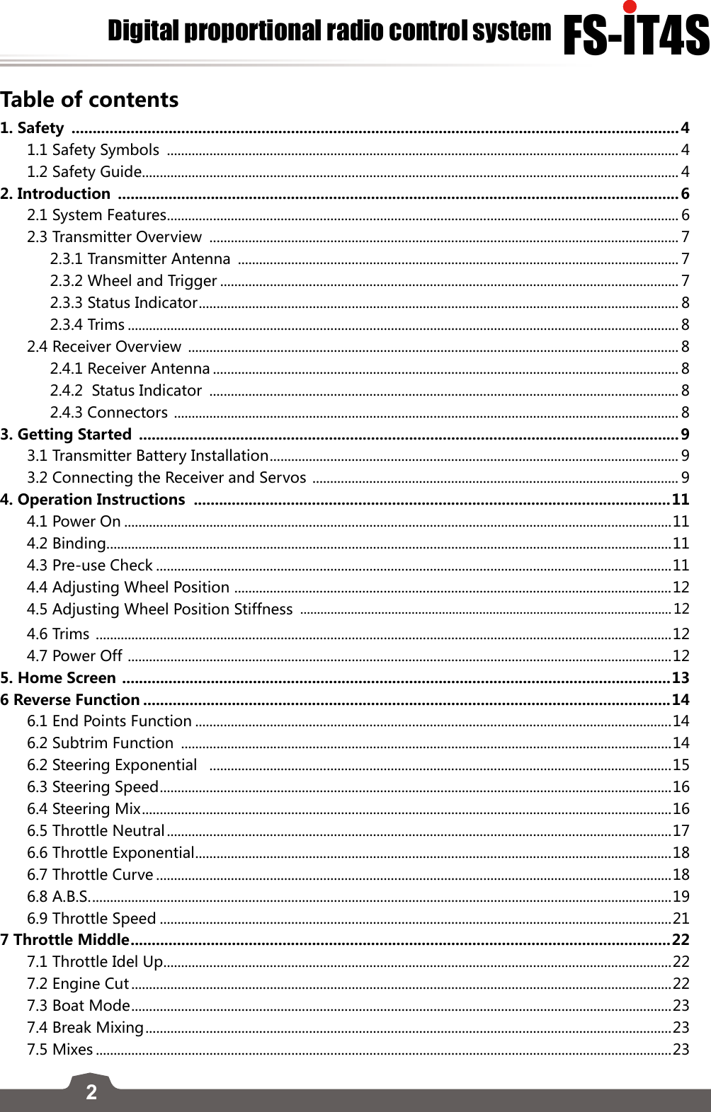
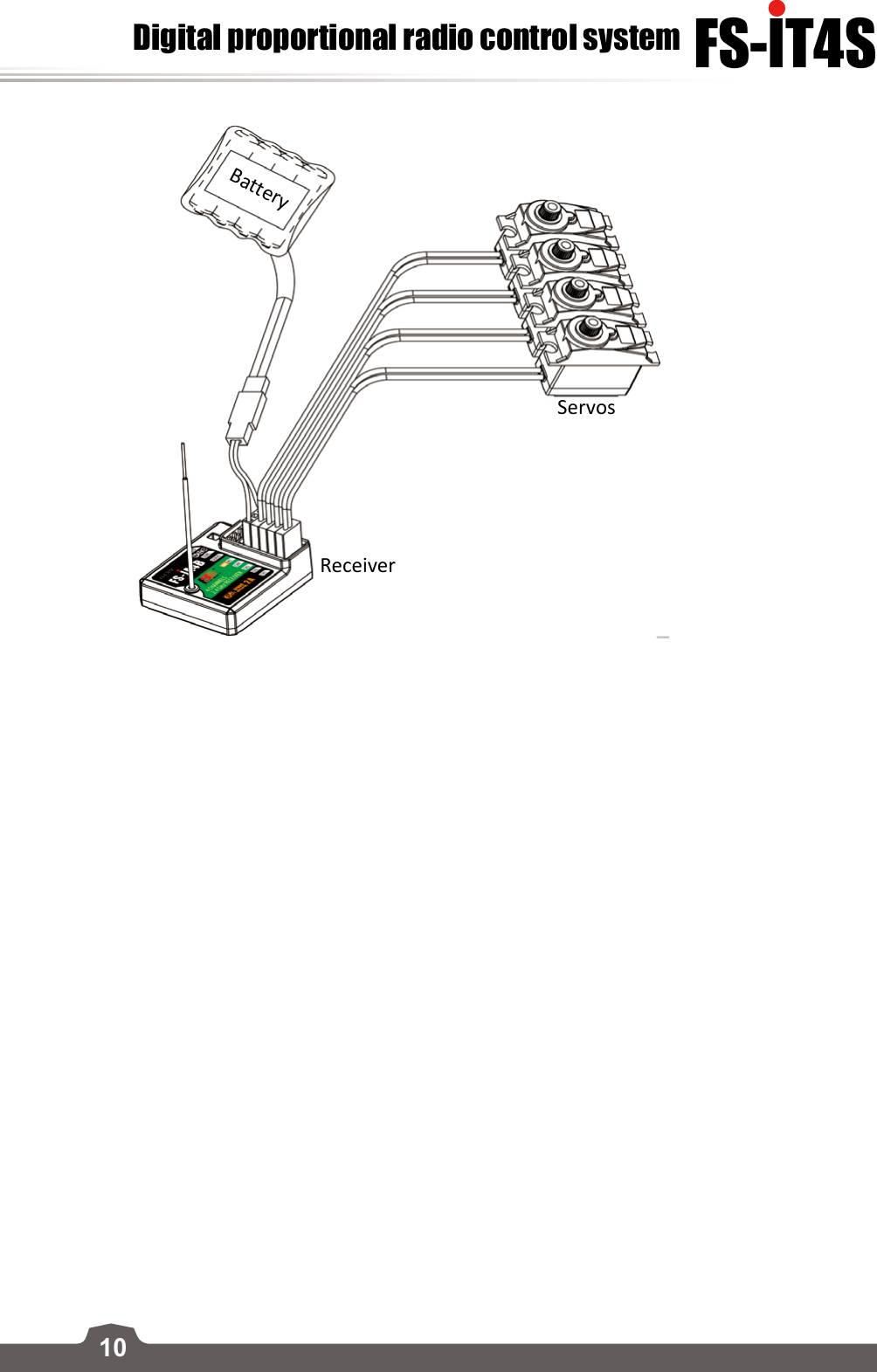
![114. Operation Instructions After setting up, follow the instructions below to operate the system.4.1 Power OnFollow the steps below to turn on the system:1. Check the system and make sure that: ▫The battery is fully charged and installed properly. ▫The receiver is correctly installed. 2. Hold the power button until screen lights up. 3. Connect the receiver power supply. The system is start now. Operate with caution, or serious injury could result.4.2 BindingThe transmitter and receiver have been pre-bound before delivery. If you are using another transmitter or receiver, follow the steps below to bind the transmitter and receiver:1. Make sure a battery is installed in the transmitter and that the transmitter is turned off.2. Connect the bind cable to the B/PPM connector of the receiver.3. Connect the power to any of the CH1 to CH4 connectors. The indicator will start to flash, indicating that the receiver is in binding mode.4. Turn the transmitter on and navagate to [RX Setup] by pressing and swiping from right to left on the screen and selecting the RX setup icon. Select [Bind with a receiver] and press yes to enter bind mode. 5. On the receiver, connect the bind cable into the bind port and connect the power. Once the binding is complete the transmitter should exit the bind menu automaticlly (Note: This only applys to two-way communication protocols).6. Remove the bind cable from the receiver. 7. Check if all the servos work as expected. If anything is doesn't work as expected, restart this procedure from the beginning.4.3 Pre-use CheckBefore operation, perform the following steps to check the system:1. Check to make sure that all servos and motors are working as expected2. Check operating distance distance: one operator holds the transmitter, and another one moves the model away from the transmitter. Check the model and mark the distance from where the model starts to lose control. (Note: Sources of interference may affect signal quality)Danger • Stop operation if any abnormal activity is observed. Danger • Make sure the model flies within the safe distance.](https://usermanual.wiki/FLYSKY-RC-MODEL-TECHNOLOGY/FLYSKYIT4S/User-Guide-2734613-Page-12.png)
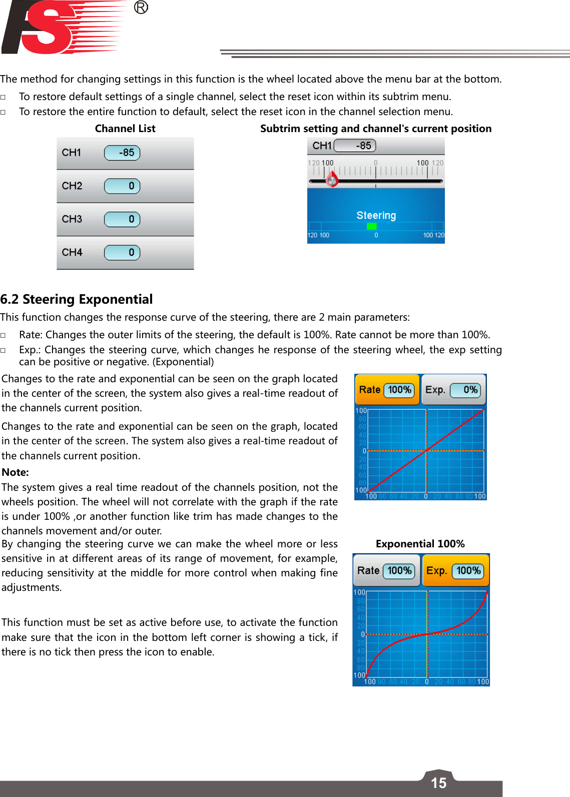
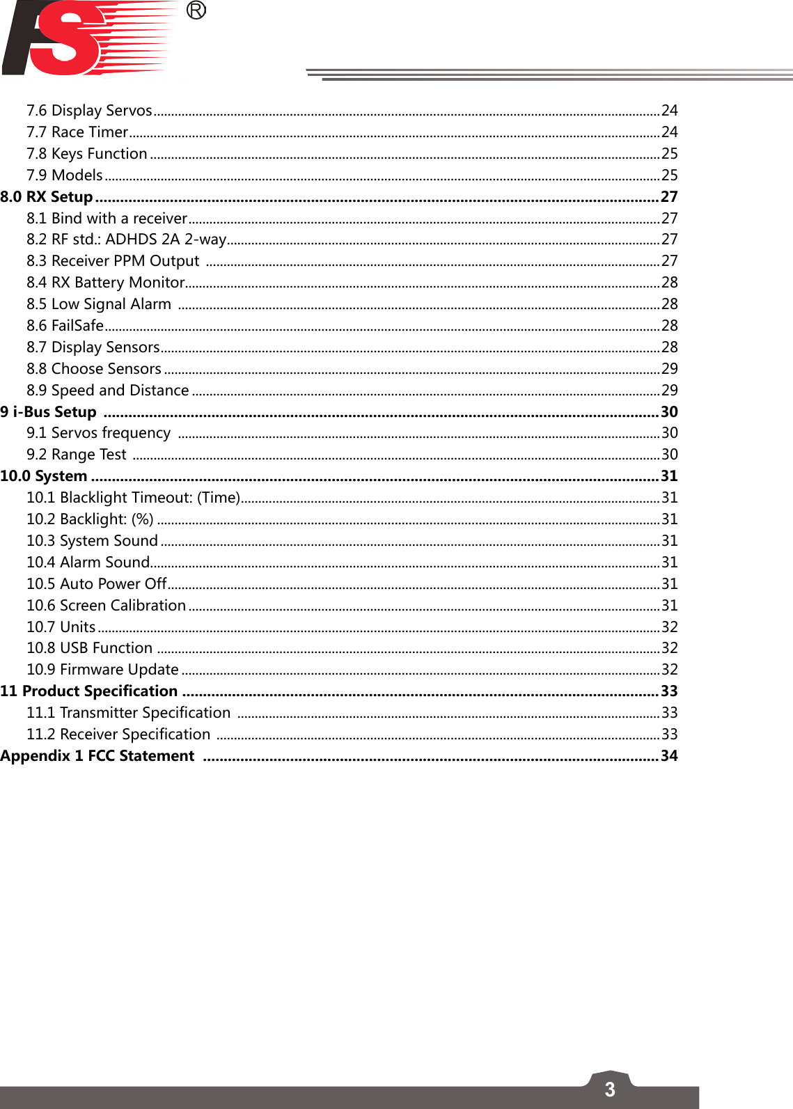
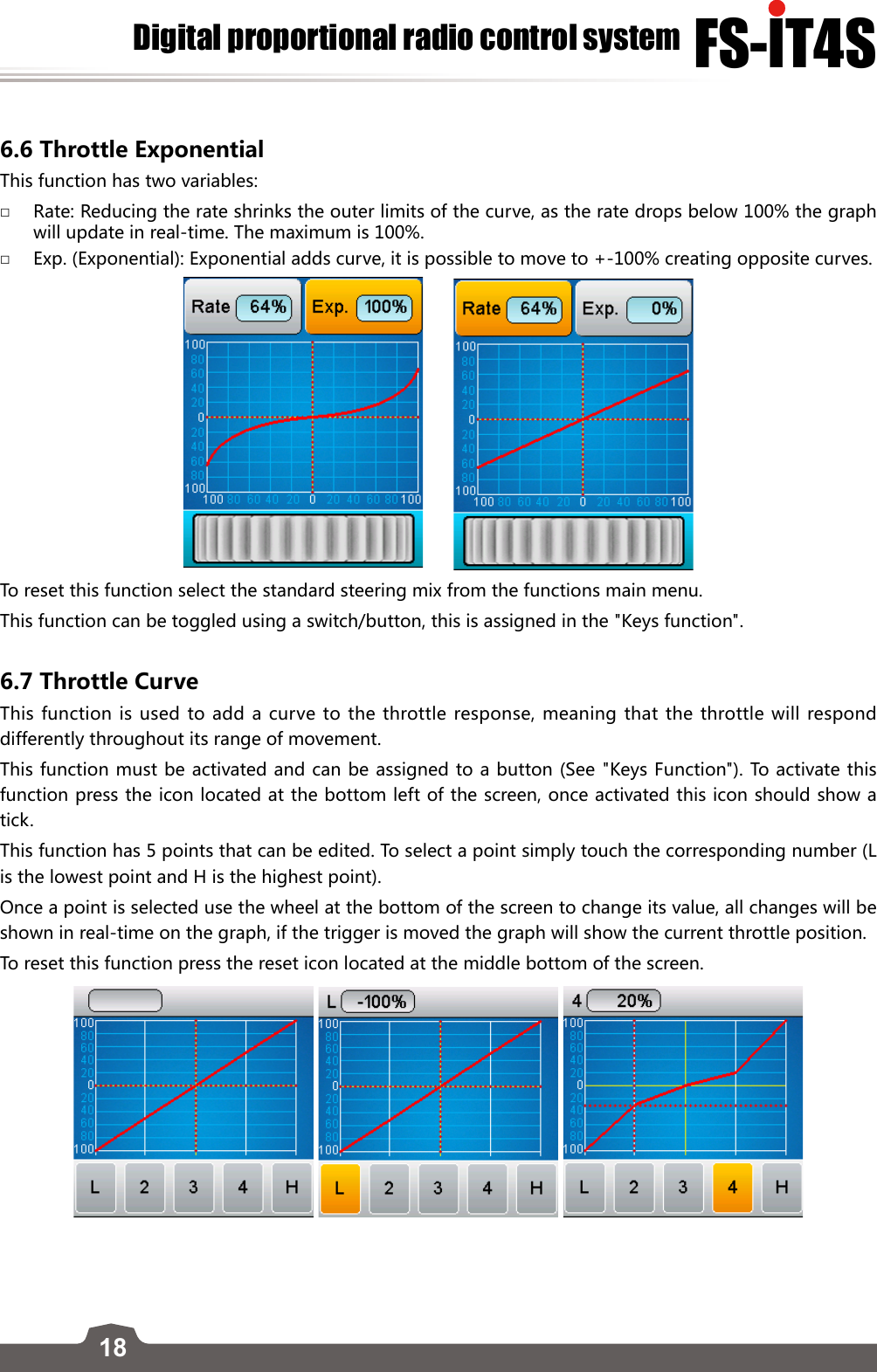
![16FS-lT4SDigital proportional radio control systemTo set the steering exponential/rate:1. Select the desired parameter, rate or exp.2. Use the wheel at the bottom of the screen to change the value. To restore the entire function to default, select the reset icon located at the bottom center of the screen.This function can be toggled using a switch/button, this is assigned in the [Keys function]. To restore the entire function to default, select the reset icon located at the bottom center of the screen.Exponential 0% Rate 64%6.3 Steering SpeedThis function changes the speed in which the steering travels, if the cars wheels are turning too fast, it could lead to loss of control, on the other hand if they don’t change position fast enough the car will become sluggish and slow to make turns. This function is also used to simulate a realistic for scale models. There are two variables:Turn Speed: Sets how quickly the wheels turn from their starting position, to the position the systems controls indicates.Return Speed: Sets how quickly the wheels turn back to their center position. To set the steering speed:1. Select a parameter to change.2. Use the wheel at the bottom of the screen to change the value. To restore the entire function to default, select the reset icon located at the bottom center of the screen.6.4 Steering MixThis function changes which wheels are involved in steering, front, rear, or 4 wheel steering. To enable this function select “crawler mode” from the functions main menu.](https://usermanual.wiki/FLYSKY-RC-MODEL-TECHNOLOGY/FLYSKYIT4S/User-Guide-2734613-Page-17.png)
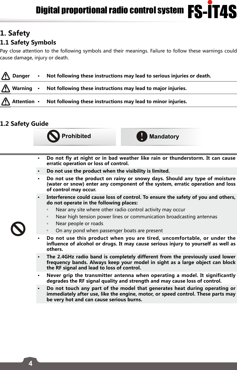
![17There are 4 types of steering control: □Font side: Front wheel steering. (Default) □Rear side: Rear wheel steering. □Same phase: Front and rear steering at the same time, when turning a direction all the wheels will turn the same direction. □Rev. phase (Reverse Phase): The front wheels and back wheels are both involved in the turning process however, the rear wheels will always turn the opposite direction to the front wheels. To set the steering mix: Select the desired method of steering, the system shows a preview of the steering method on the screen in real-time when moving the system wheel.To reset this function, select the reset icon located at the bottom middle of the screen. 6.5 Throttle NeutralThis function can set a “dead zone” for their throttle control, this means that the throttle will not function while still within the dead zone. It is also possible to set up the initial amount of throttle that will be applied when the throttle leaves the dead zone, although this can only be set for driving forward, not in reverse. To set the throttle neutral: □Dead zone To setup the dead zone select the dead zone option at the left side of the screen, and use the wheel at the bottom of the screen to change the value. The current percentage will be shown above the graph, labeled as dead zone. □Forward First select [Forward], next move the wheel to set its value.Once finished setting up these functions, press the back icon located at the bottom right of the screen to save.](https://usermanual.wiki/FLYSKY-RC-MODEL-TECHNOLOGY/FLYSKYIT4S/User-Guide-2734613-Page-18.png)
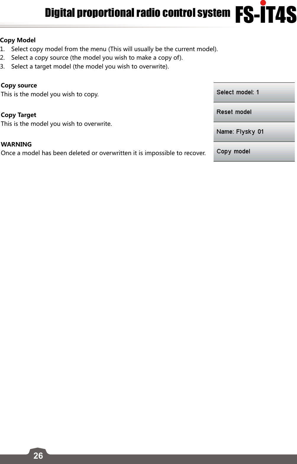
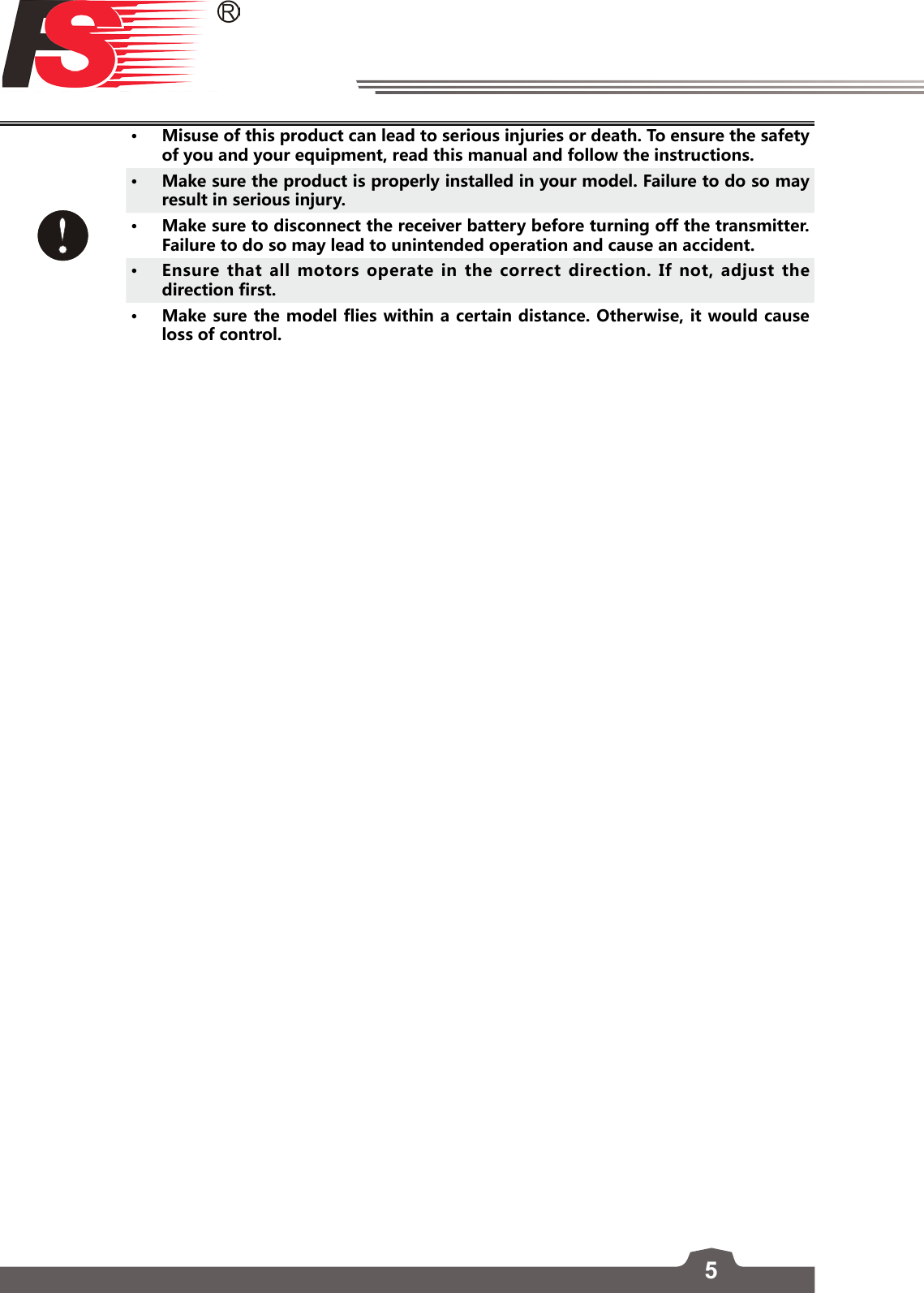
![257.8 Keys FunctionThis function assigns the systems physical buttons to different functions. To assign a function to a key select the key from the diagram, then select a function from the list. WARNINGIf the model engine is powered on while the test function is activated will rev up.To set the keys function:1. Touch one of the trim or switches shown on the diagram.2. Scroll down the list until you find the function you wish to assign and select it.3. Once the selection has been made the function will automatically return to the previous menu. 7.9 ModelsThe models function is used to change between, copy and delete model setups. The FS-iT4S can store up to 20 different models in the internal memory.Selecting a model:To select a model touch the select model menu, once in the menu touch the name of the model to load it. Reset ModelTo reset (delete model by resetting to default), first select a model from the model selection menu (as shown above), then press the reset model button. The system will ask for a confirmation before resetting the model. Naming ModelsTo name a model, fist select a model from the model selection menu (as shown above), then touch the name menu button which will bring up a keyboard. Once you have finished entering in the name using the keyboard press the [Icon] to save.](https://usermanual.wiki/FLYSKY-RC-MODEL-TECHNOLOGY/FLYSKYIT4S/User-Guide-2734613-Page-26.png)