FLYTECH TECHNOLOGY J680222 POS User Manual J2 680 System Manual 1 0
FLYTECH TECHNOLOGY CO., LTD POS J2 680 System Manual 1 0
Contents
- 1. Users Manual_part 1 of 2
- 2. Users Manual_part 2 of 2
Users Manual_part 2 of 2
J2 680 System Manual
Version 1.0 May 11, 2012
36
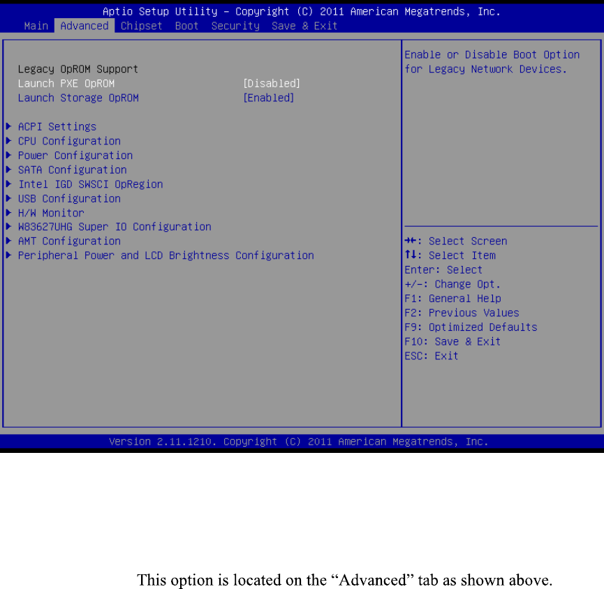
Advanced Settings
This menu contains settings to control a number of system functions. Most these settings
are self-explanatory.
Advanced Setting Screen
Launch PXE ROM
This setting enables the built- in PXE LAN remote boot rom. This allows the system to
run as a diskless workstation, or to be able to download a drive image to a blank drive.
When enabled, a message screen will appear and Shift-F10 can be typed to access the
PXE ROM options.
J2 680 System Manual
Version 1.0 May 11, 2012
37
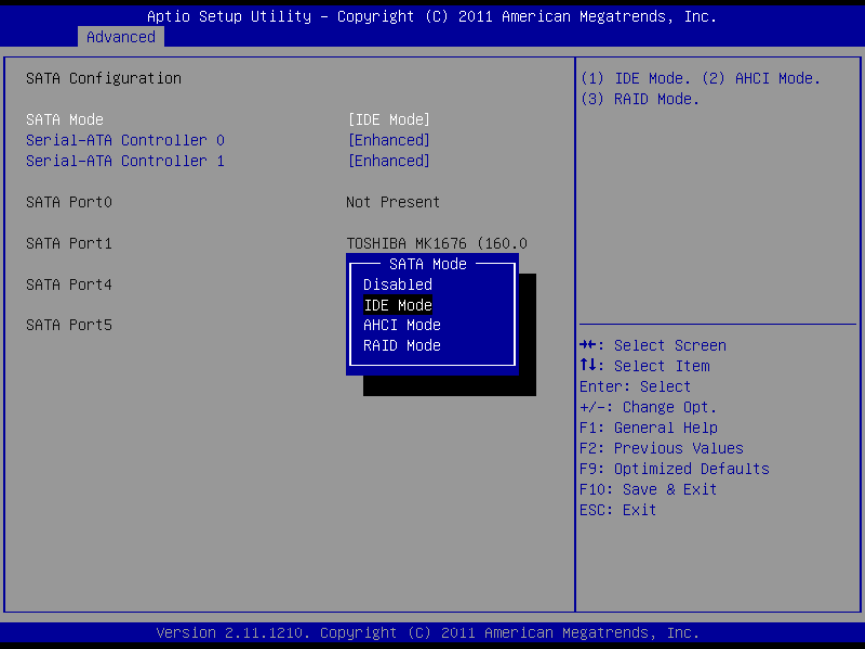
SATA Configuration
In this screen the SATA hard drives can be set to work in one of three modes, SATA,
RAID or AHCI.
When set to SATA, the SATA drive works the same as a normal IDE HDD. This is the
IDE compatible mode and default BIOS setting. The other two selections are RAID and
AHCI modes. Please see the separate section in the manual for RAID Setup for further
information on using RAID and AHCI modes.
SATA Configuration Screen
J2 680 System Manual
Version 1.0 May 11, 2012
38
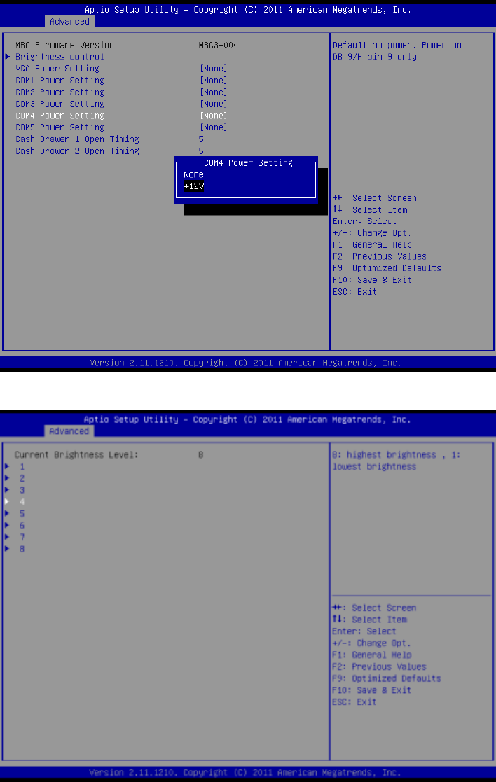
Peripheral Power and LCD Brightness Configuration
This submenu allows for the enabling of power for the serial ports, default cash drawer
pulse timing and default LCD brightness level and power for a J2 supplied VGA port
monitor.
Power enable for serial Ports
LCD Brightness Setting
J2 680 System Manual
Version 1.0 May 11, 2012
39
Power Configure Screen
Power Configure Screen
Restore on AC Power Loss
The 680 has three options should AC power become lost and then restored. There is
Power Off (stay turned off), Power On (turn on when AC restored), or Last State. The
Last State setting will cause the unit to turn on if it was on when AC power was lost or it
will stay off if the unit was off when AC power was lost.
Wake on LAN
Wake on LAN is enabled by default but can be disabled in this screen.
RTC Configuration
The RTC has an alarm function that can be used to turn the 680 on at a preset time of
day. This function is enabled by this setting. The wake up time can also be set here.
J2 also has available a utility to set the wake-up time from Windows. This is more
versatile than the BIOS setting as it allows for more than one time of day to be set as well
as days of the week to turn on.
J2 680 System Manual
Version 1.0 May 11, 2012
40
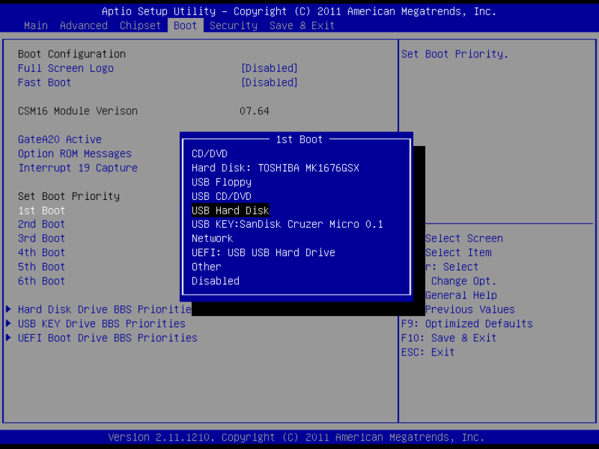
Boot Settings
If more than one bootable device is in the system the boot order can be set in this menu.
If a bootable USB storage device is plugged in at boot up the 680 will boot from that
device by default. If this is not desired the boot order can be changed here. A list of
detected drives will be displayed with the current boot order.
Boot Settings Screen
Display OEM Logo
The BIOS can display two types of OEM logos on boot up. The default is a small J2 logo
in the upper left hand corner. With this setting BIOS POST test messages can be seen
during boot up. The second type which is enabled by this entry is a full screen J2 logo.
When this logo is selected the BIOS POST messages cannot be seen. The BIOS setup can
still be entered by typing the DEL key a few seconds after the logo appears.
Customer logos can replace the J2 logos when required. Please contact J2 regarding this,
if required.
J2 680 System Manual
Version 1.0 May 11, 2012
41
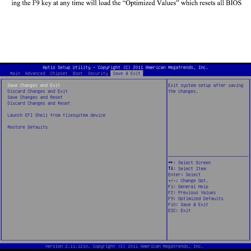
Exit Options
After making any changes to the BIOS settings, the changes can be saved from this
screen. Any changes can be discarded as well or the factory BIOS defaults can be loaded.
Typ
setting to the factory defaults.
It should be noted that to save changes to the BIOS setup the F10 key can be typed from
any screen to save the BIOS changes. It is not necessary to exit setup from this screen.
To discard any BIOS setup changes you can type the ESC key from any screen to exit.
Exit Options Screen
J2 680 System Manual
Version 1.0 May 11, 2012
42
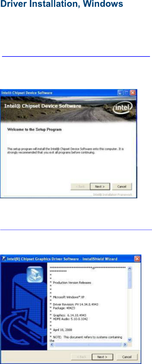
Chipset Driver Installation
The chipset driver is needed to get the full potential from the 680 chipset. It should be
loaded before other drivers and first thing after booting. The drivers can be downloaded
from the J2 web site:
http://www.j2retailsystems.com/support/680/Chipset/.
After extracting the drivers to a temporary folder, run Setup.
Just answer Next or Yes to all the screen prompts and the drivers will install.
Graphics Driver Installation
You can download the 680 graphics driver from the J2 web site at:
http://www.j2retailsystems.com/support/680/Graphics/.
This is an .exe file so just run it and answer Next or Yes to all screen prompts and the
drivers will install. The last screen will ask if you want to reboot, answer Yes.
J2 680 System Manual
Version 1.0 May 11, 2012
43
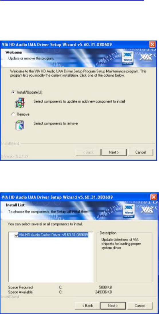
Audio Driver Installation
The Audio Drivers can be downloaded from the J2 web site at:
http://www.j2retailsystems.com/support/680/Audio/.
After extracting the driver to a temporary folder, run Setup, and then follow the
instructions below:
First Audio setup screen
Just click on Next to install the Audio driver.
Second Audio setup screen
Check the Codec Driver box, and then click Next. Answer Next to any more dialog
boxes, then Finish. The system will need to be rebooted before the audio drivers take
effect.
J2 680 System Manual
Version 1.0 May 11, 2012
44
LAN Driver Installation
The LAN drivers can be downloaded from the J2 web site:
http://www.j2retailsystems.com/support/680/LAN/.
After extracting the driver to a temporary folder, run Setup. Just answer Next or Yes to
all the screen prompts and the driver will install.
LAN driver install screen
J2 680 System Manual
Version 1.0 May 11, 2012
45
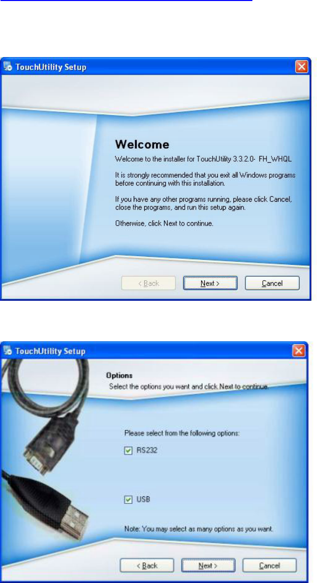
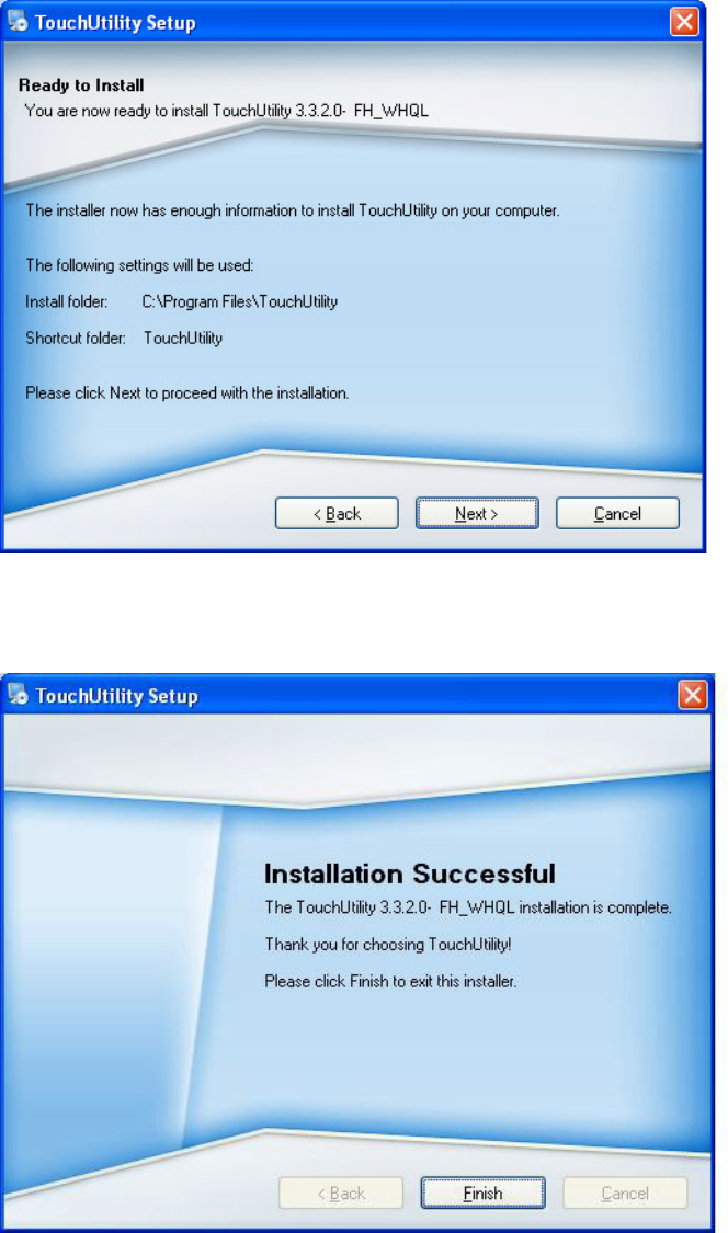
Resistive Touch Screen Driver Installation
The Touch Drivers can be downloaded from the J2 web site at:
http://www.j2retailsystems.com/support/680/Touch/.
When run, the diver will display a welcome screen, at this point just press next for the
next few screens.
When you get to this screen check both RS232 and USB options and click next.
Just click till this screen and then click next and the driver will finish installing.
J2 680 System Manual
Version 1.0 May 11, 2012
46
Click finish at the screen. The driver will then detect the port the touch screen is on
(normally COM6) then ask you to reboot the system.
After rebooting the touch should be working. Calibration is not needed as this is done at
the factory.
J2 680 System Manual
Version 1.0 May 11, 2012
47
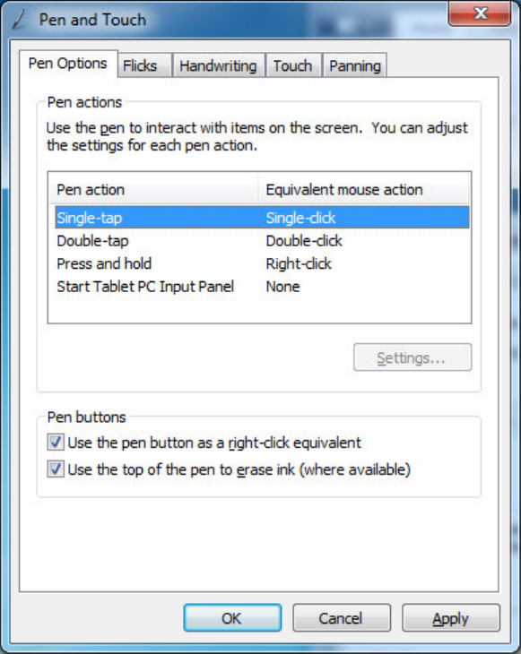
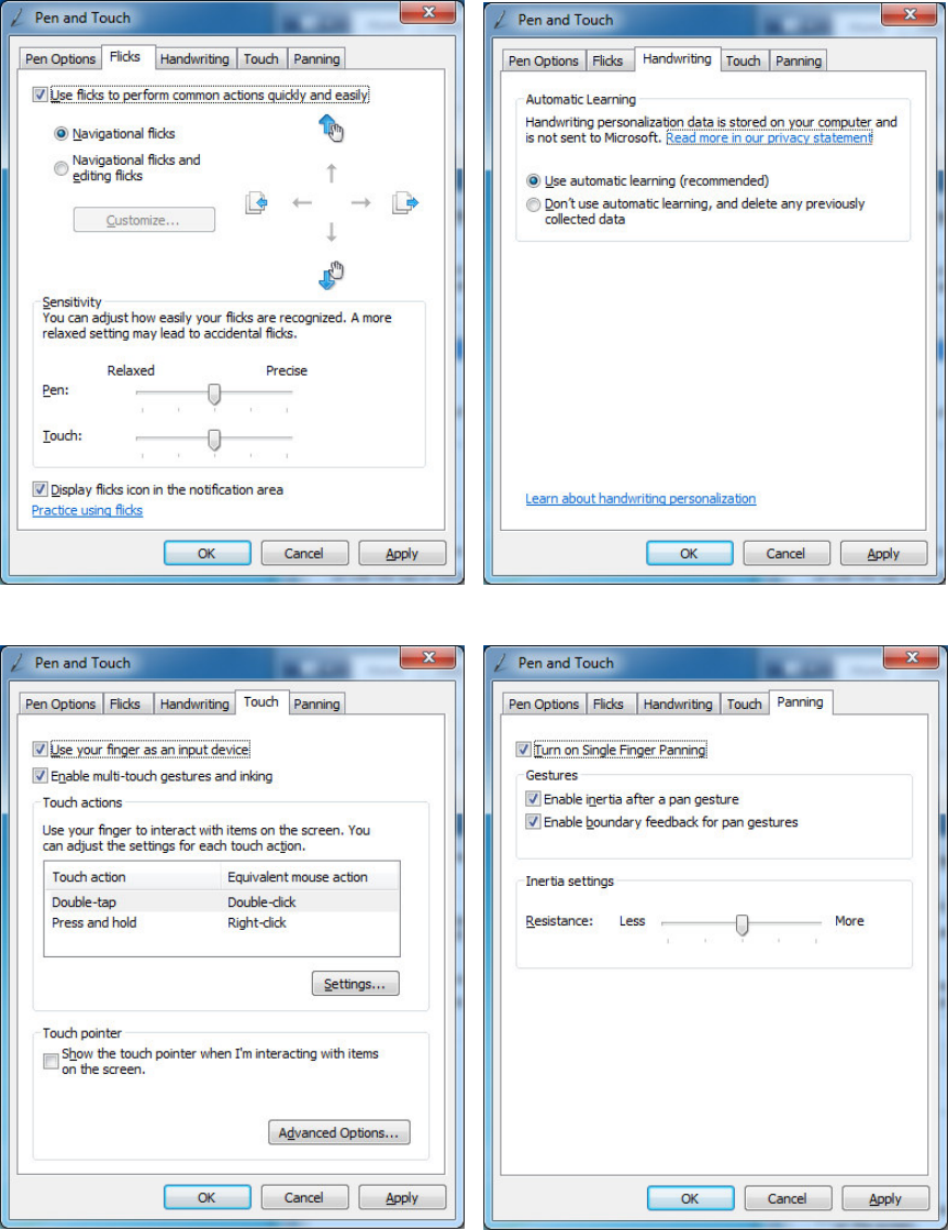
Multi-Touch Projected Capacitive Touch Driver
No touch driver needs to be loaded for the PCT touch screen because it uses the
Microsoft built in pen and touch driver, No calibration is needed for the projected
capacitive touch screen. The driver options can be accessed via the Windows control
panel. The built in Windows pen and touch driver is present in XP, Vista and all versions
Windows 7.
The first page of options allows for the change how your finger or stylus interacts with
the screen. The sensitivity and function of touch to the screen can be changed here.
J2 680 System Manual
Version 1.0 May 11, 2012
48
The other four option tabs are shown below for reference. They are self-explanatory in
most case and additional information can be obtained through the Windows help
function.
J2 680 System Manual
Version 1.0 May 11, 2012
49
Optional Multi-Touch Projected Capacitive Touch Driver
In addition to the Windows built in standard touch driver J2 also supplies and optional
touch driver that is used when multi-monitor touch support is needed. This driver works
with Windows XP and later version of Windows. The driver can be downloading from
J2 web site.
To install just extract the zip file where you wish to run it from and run setup. When
asked to install PS/2 or RS-232 driver answer no, the PCT controller is a USB device.
When the install is complete it will ask if you wish to do a 4 point calibration, answer no
to this as the PCT screen does not need calibration. The touch will now be working.
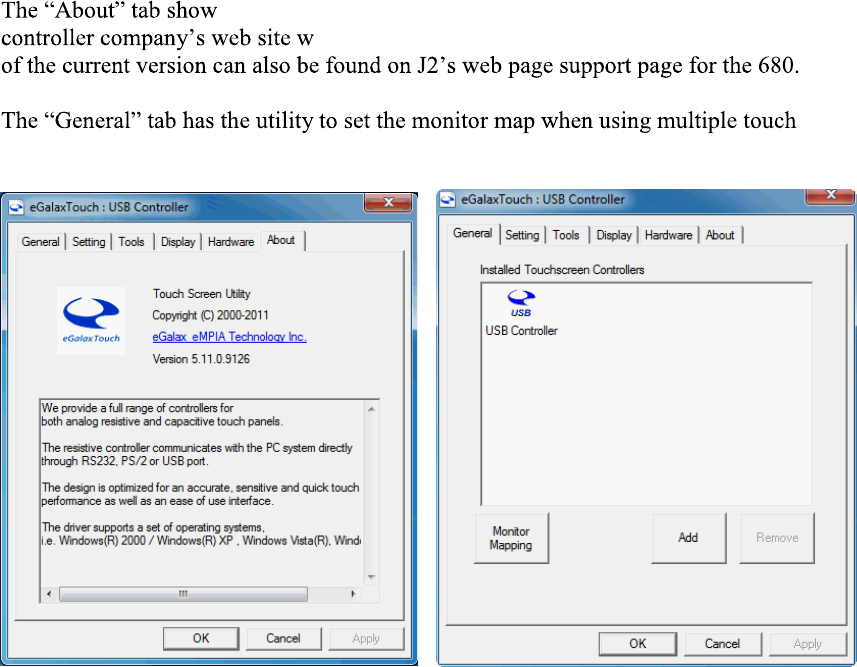
The PCT touch configuration utility can be found in programs under eGalax Touch,
Configuration Utility. This program allows for the configuration of the touch screen
option.
s the current version of the touch screen plus has a link to the touch
here the latest version of the driver can be found. A copy
monitors.
J2 680 System Manual
Version 1.0 May 11, 2012
50
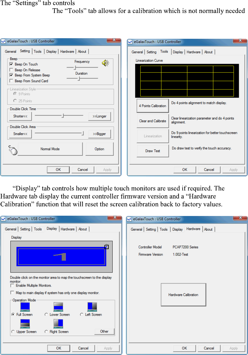
the touch on beep, double click function and right mouse
button emulation.
for a PCT screen. A draw test is provided to verily the operation and calibration of the
touch screen.
The

J2 680 System Manual
Version 1.0 May 11, 2012
51
OPOS drivers
The OPOS driver for the 680 supports the Cash Drawer ports, the optional MSR,
the optional 2x20 character Customer Display, and the optional iButton reader.
The OPOS driver may be downloaded from the J2 web site at:
http://www.j2retailsystems.com/support/680/.
Just run the OPOS setup.exe file to install.
J2 680 System Manual
Version 1.0 May 11, 2012
52
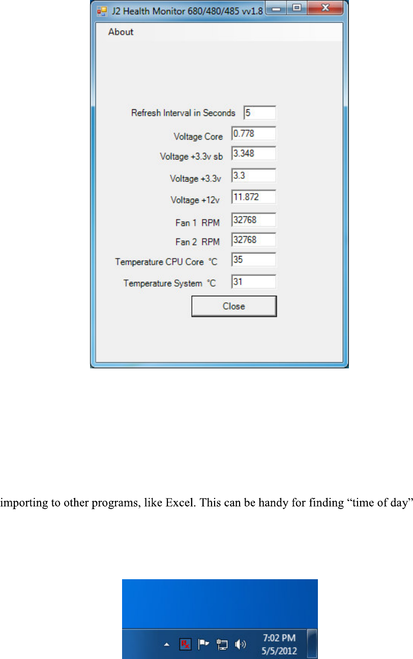
J2 has a standard program that works with all its POS products, called J2 Health. This
program is used in either a standalone mode or in conjunction with J2 remote
monitor/asset tracking software. The J2 Health program monitors different aspects of the
POS hardware to ensure the hardware is running within specification. For the J2 680 it
monitors critical system voltages, as well as system and CPU temperatures.
Installation
The utility can be downloaded from the J2 web site:
http://support.j2rs.com/Utilities/Health/ To install just unzip anywhere and run setup.
Like other J2 utilities it can be uninstalled through the Windows control panel.
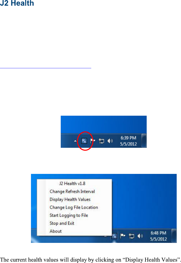
Tray Icon
Once installed and the system has rebooted, J2 Health will be running in the background.
The J2 health icon will appear in the task bar tray:
Right-clicking on this icon displays different Health options, shown below:
A sample screen is shown below:
J2 680 System Manual
Version 1.0 May 11, 2012
53
As can be seen above, when running on the J2 680 the J2 Health program displays critical
system voltages and system and CPU Core temperatures. For other J2 POS systems, J2
Health may display more or less information. An example would be the J2 680 unit,
which in addition to the above information would also display the fan speed of the two J2
680 fans.
Logging to File
The J2 Health program can log the health data to a file in the csv text format for
related problems.
When logging is enabled, the tray icon Rx symbol will change to red to indicate logging
in is taking place.
J2 680 System Manual
Version 1.0 May 11, 2012
54
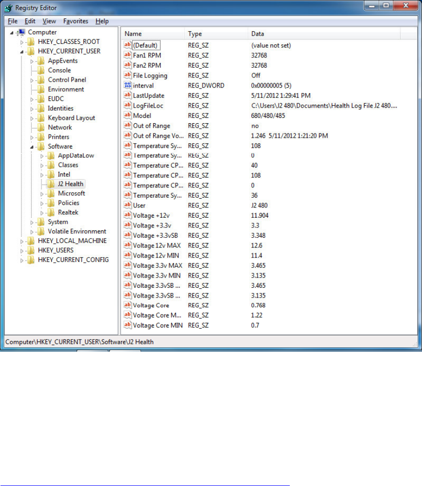
Registry Entries
The J2 Health program creates registry entries for the different health values. Dynamic
values are updated at the user defined interval, which is by default 5 seconds. Other
software may use these registry entries to access the J2 health information.
J2 680 Health keys are shown below:
J2 Remote Monitoring Software
J2 now offers a full remote monitoring and asset tracking solution that works in
conjunction with J2 Health to ensure the highest uptime possible of your POS hardware.
Please contact J2 sales for more information on this fully customizable, remote monitor
solution.
For more information, please visit us at
http://www.j2retailsystems.com/newsarticle.php?news_id=57
J2 680 System Manual
Version 1.0 May 11, 2012
55
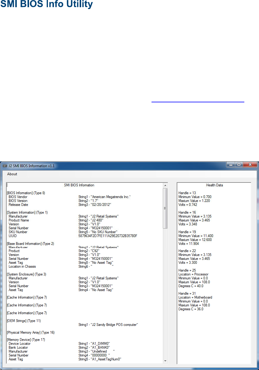
The J2 SMI BIOS Info program allows for the reading of all populated BIOS DMI/SMI
information. With some J2 products including the J2 680, this information also includes
dynamic system health information. Normally this dynamic DMI health information
BIOS is only supported on very high end servers. Now J2 brings this feature to POS
hardware.
The J2 SMI BIOS Info program will run on any J2 POS hardware or for that fact on any
PC hardware. It can display all DMI/SMI information on a formatted form.
Installation
The utility can be downloaded from the J2 web site: http://support.j2rs.com/Utilities/
To install just unzip anywhere and run as you wish to run the utility form.
Operations
Just click on the .exe file to run. The following screen will be displayed (see below).
Note that the health data will only display on newer J2 systems that support the dynamic
DMI health BIOS.
J2 680 System Manual
Version 1.0 May 11, 2012
56
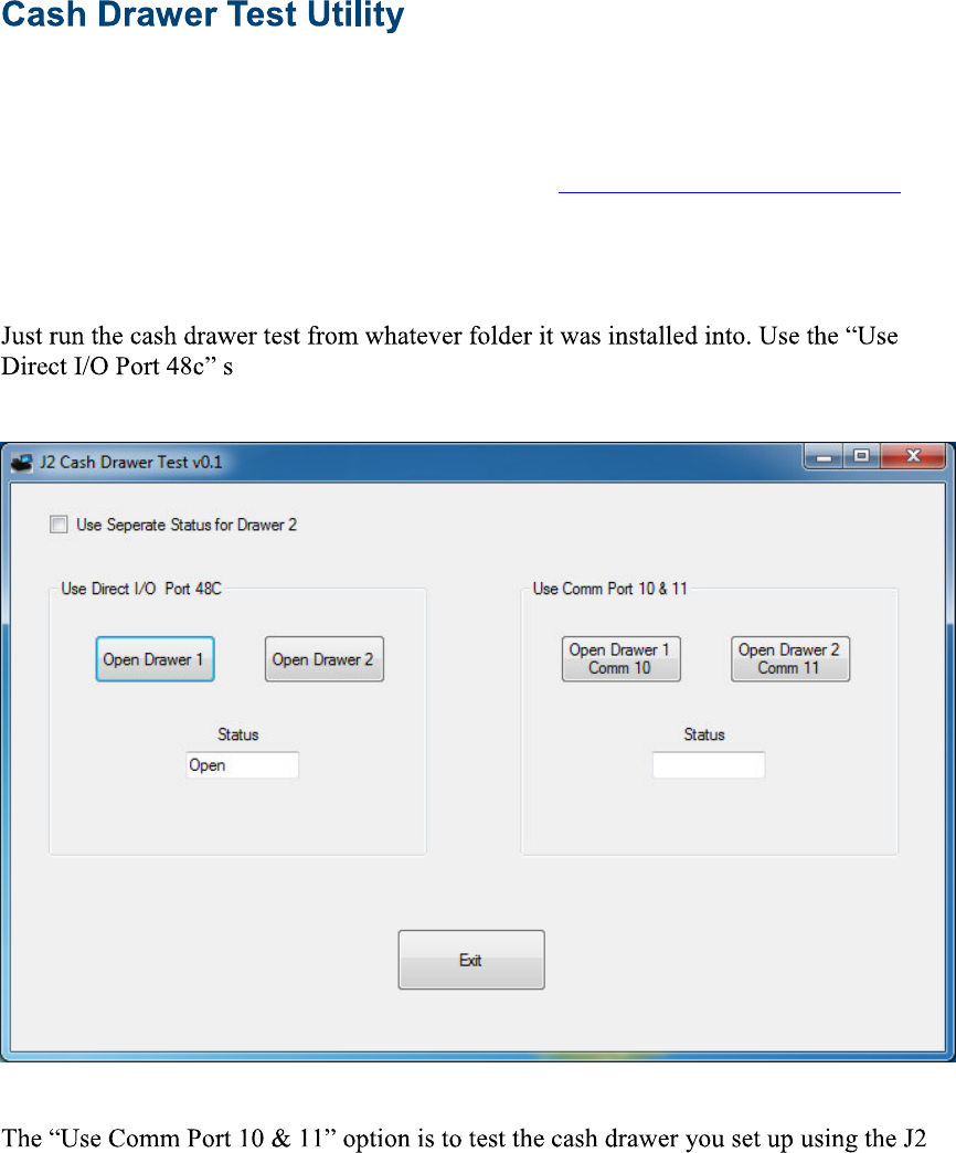
J2 has a generic cash drawer test utility that works on all J2 products, including the new
J2 680 computer.
Installation
The utility can be downloaded from the J2 web site: http://support.j2rs.com/Utilities/
To install just unzip anywhere and run as you wish to download the utility form.
Operation
etting to test the cash drawer(s). (see example below)
virtual serial ports program. The virtual serial port program must be installed with the
cash drawer virtual serial ports set to Comm 10 & 11.
J2 680 System Manual
Version 1.0 May 11, 2012
57
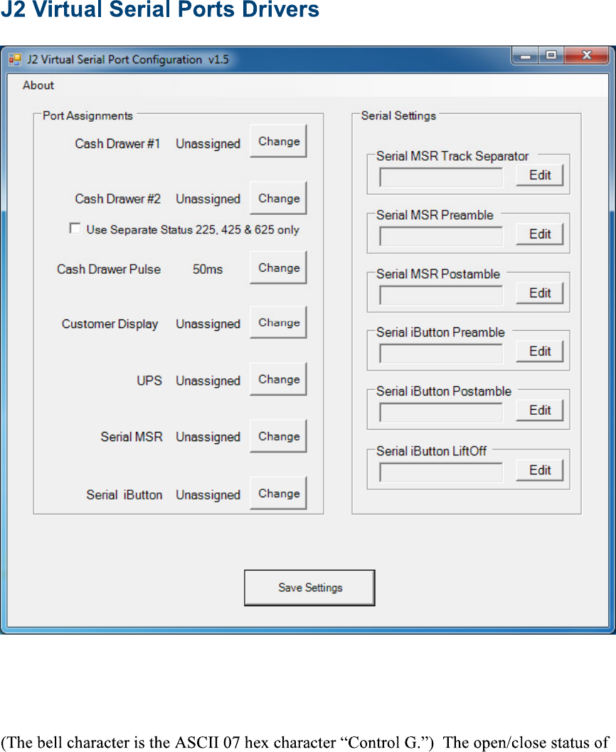
Virtual serial ports can be used for the cash drawers, virtual 2x20 line display on the
optional 10.1 LCD, Smart UPS, MSR and iButton.
To open virtual serial cash drawer send a bell character to the Com port it is assigned too.
the drawer may be obtained by reading the status bits of its COM port. The drawer
open/close status will be reflected on the CTS and RI bits, either bit may be used. This
virtual COM port driver is designed to work the same as a hardware serial cash drawer
and will work with drivers for serial cash drawers.

J2 680 System Manual
Version 1.0 May 11, 2012
58
RAID Overview
The 680 uses the Intel Matrix Storage Technology to allow the two internal 2.5 inch hard
drives to be configured as a RAID array. The 680 supports RAID 0, RAID 1 and Intel
Matrix RAID which combines the benefits of two RAID volumes in a single RAID array.
If you are not currently familiar with RAID arrays Intel has a good white paper on the
subject at: http://www.intel.com/design/chipsets/applnots/310855.htm
There are a number of benefits to using the RAID feature.
Protection is one benefit. When using a RAID 1 array, data is protected by mirroring.
The primary RAID volume is duplicated automatically on the second drive, a mirror
image of the first. If one of the two hard drives fails the system will still keep working.
The bad hard drive can be replaced while the system is running. This is called hot
swapping or hot plug. The new drive will automatically be updated to a mirror image of
the working drive.
Performance is another feature RAID can provide. When configured as a RAID 0 array
the two drives in the RAID array are striped. With striping, data is split between two
drives. This allows the 680 to read the data more than twice as fast as with a single drive.
The performance can be more than twice as fast because the Intel RAID driver also uses
the AHCI NCQ function built into the SATA drives.
Protection and Performance can be mixed using an Intel Matrix RAID configuration,
whereby a RAID 1 and RAID 0 can be setup on the same RAID array. Mission critical
data can be stored in the RAID 1 volume and data requiring performance can be stored on
the RAID 0 volume.
AHCI
AHCI stands for Advanced Host Controller Interface and is a feature of the SATA
interface that allows for Hot Swapping and Native Command Queuing (NCQ).
NCQ allows multiple commands to be sent to the hard drive at one time. The drive
decides the best way to order the commands for the best performance from the drive.
AHCI is enabled when RAID mode is selected in the BIOS setup.
To use AHCI drivers from Intel the BIOS must be set to RAID, not AHCI. The AHCI
mode uses the same drivers as used for RAID. Follow the instruction for install the RAID
drivers but set the HDD as a Non-RAID Disk in the RAID BIOS setup.

J2 680 System Manual
Version 1.0 May 11, 2012
59
Enabling RAID in the BIOS
The Intel manual for the Intel Matrix Storage Manager covers this same information
given below in more detail and can be downloaded from the J2 web site. The
documentation below is tailored for the 680 only.
Link: http://www.j2retailsystems.com/support/680/RAID/
Perform the following steps to enable the RAID option in the system BIOS:
1. Enter the BIOS Setup program by pressing the DEL key after the BIOS sign-on
screen appears.
2. Select the Advanced menu, and then the SATA Configuration menu.
3. Switch the Configure SATA Ports option from SATA to RAID.
4. Press the F10 key to save the BIOS settings and exit the BIOS Setup program.
RAID Volume Creation
Perform the following steps to create a RAID volume:
1. When the Intel Matrix Storage Manager option ROM status screen appears during
POST, press the Ctrl and i keys at the same time to enter the Intel Matrix Storage
Manager option ROM user interface.
2. Select Option 1: Create RAID Volume and press the Enter key.
3. Use the up or down arrow keys to select the RAID level and press the Enter key.
4. Unless you have selected RAID 1, use the up or down arrow keys to select the
stripe size and press the Enter key.
5. Press the Enter key to select the physical disks.
6. Select the appropriate number of hard drives by using the up or down arrow keys
to scroll through the list of hard drives and pressing the Space key to select the
drive. When finished, press the Enter key.
7. Select the volume size and press the Enter key.
8. Press the Enter key to create the volume. At the prompt, press the Y key to
confirm volume creation.
9. Select Option 4: Exit and press the Enter key. Press the Y key to confirm exit.
F6 Installation Method
Note: For this step you will need both a USB CD ROM and USB Floppy.
Drivers can be downloaded here: http://www.j2retailsystems.com/support/680/RAID/
(continued on next page)
J2 680 System Manual
Version 1.0 May 11, 2012
60
Perform the following steps to install the Intel Matrix Storage Manager driver during
operating system setup:
1. Press the F6 key when prompted in the status line with the Press F6 if you need to
install a third party SCSI or RAID driver message. This message appears at the
beginning of Windows XP setup (during text-mode phase).
Note: Nothing will happen immediately after pressing F6. Setup will temporarily
continue loading drivers. You will then be prompted with a screen asking you to
load support for mass storage device(s).
2. Press the S key to Specify Additional Device.
3. You will be prompted to Please insert the disk labeled Manufacturer-supplied
hardware support disk into Drive A: When prompted, insert the floppy disk
containing the following files: IAAHCI.INF, IAAHCI.CAT, IASTOR.INF,
IASTOR.CAT, IASTOR.SYS, and TXTSETUP.OEM and press the Enter key.
4. After pressing Enter, you should be presented with a list of available SCSI
Adapters. Select your controller from the list. The 680 uses the ICH8R driver.
5. The next screen should confirm your selected controller. Press the Enter key
again to continue.
6. At this point, you have successfully F6'd in the Intel Matrix Storage Manager
driver and Windows setup should continue. Leave the floppy disk in the floppy
drive until the system reboots. Windows setup will need to copy the files from the
floppy again to the Windows installation folders. Once Windows setup has copied
these files again, you should then remove the floppy diskette so that Windows
setup can reboot as needed.
7. During Windows setup, create a partition and file system on the RAID volume as
you would on any physical disk.
Installing the Intel Matrix Storage Manager Software
Once XP is booted you can install the Intel Matrix Storage Manager by just running the
iata82_enu.exe install program.
install.
more information at manual70.pdf.
Hot Swapping RAID 1 drives
If a RAID 1 drive fails the Matrix Storage Manager will warn the user that a drive has
failed. A small Icon appears as shown to indicate a drive has failed.
Drive Failed Icon in tray
J2 680 System Manual
Version 1.0 May 11, 2012
61
If a hot spare is available, all that needs to be done is to swap the bad drive with the hot
spare. Be sure to change the correct drive. SATA Ports 0 corresponds to the HDD 0, the
top drive in the HDD bay and SATA Ports 1 corresponds to the HDD 1, the bottom drive
in the HDD bay.
Power to the system does not need to be turned off, and the system will still operate.
First remove the bad drive. After removing the bad drive insert the hot spare into the 680.
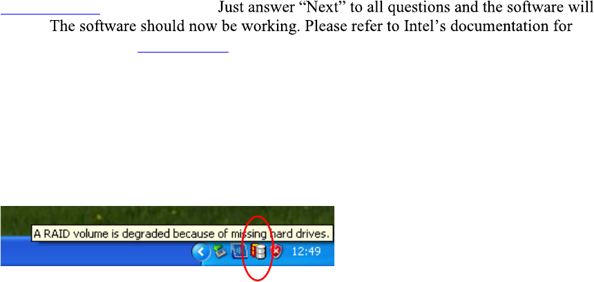
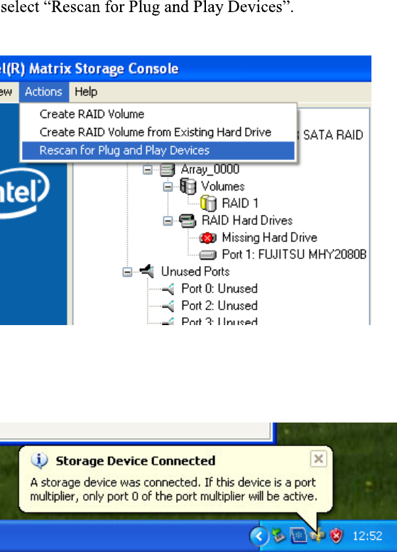
In the Intel Matrix Storage Manager select Advance Mode, and under the Action tab
Rescan for Plug and Play Devices screen shot
This will cause the drive to be detected by the driver.
Drive detected
J2 680 System Manual
Version 1.0 May 11, 2012
62
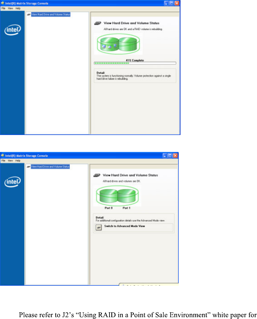
The RAID will now rebuild an image of the good drive to the hot spare.
Rebuilding
Rebuilt
The RAID has now mirrored the drive and the system is now protected for a drive failure.
Note:
more information on using the 680 RAID function. (Available September 2008)
J2 680 System Manual
Version 1.0 May 11, 2012
63
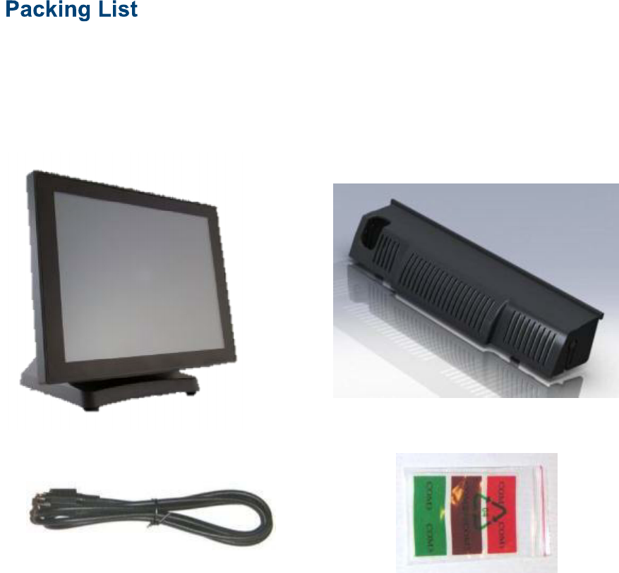
In addition to the foam packing inserts, the following contents should be found in the 680
shipping carton.
Standard Items
1: System with Power Supply and AC cord 2: Cable Well Cover
3: Printer Power Port Cable : COM Port Colored Coded Cable Labels
J2 680 System Manual
Version 1.0 May 11, 2012
64
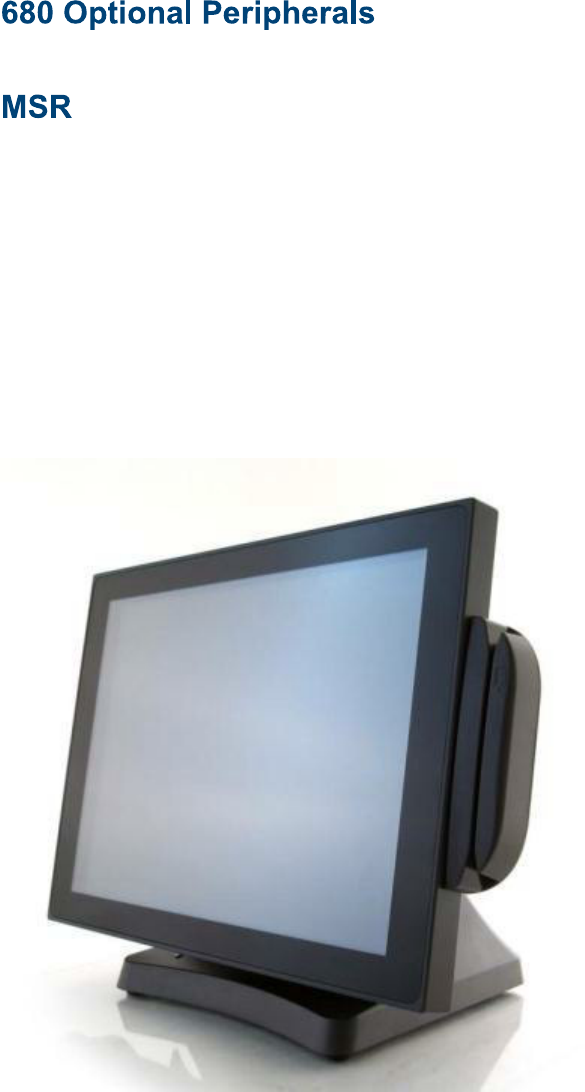
Overview
The 680 can be ordered with a 3 track MSR. This MSR is the same as used on the J2
580/615/625/630 POS systems. The MSR mounts on the right side of the 680 and uses a
front facing MSR slot. This allows the 680 unit to be placed side by side, or in tight
spaces, and still be able to swipe the card. The MSR appears to the software as a wedge
type MSR with all data from the MSR being sent to the keyboard port. The MSR
configuration utility can be down loaded from J2 web site.
680 with front swipe MSR
J2 680 System Manual
Version 1.0 May 11, 2012
65
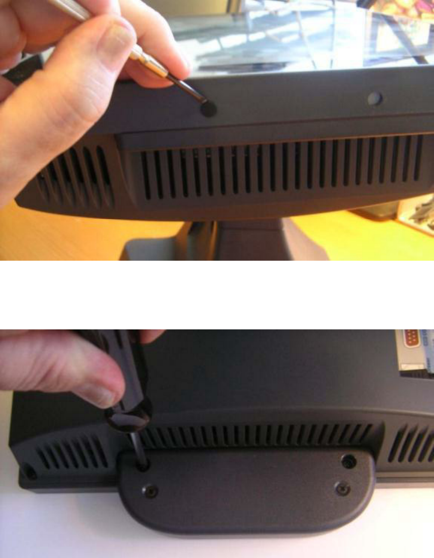
Installing the 680 MSR
The 680 MSR is installed by first removing the two rubber plugs for the option
attachment point as shown below.
Remove Rubber plugs
Then remove the MSR cover plate on the right back side of the unit by removing the two
screws, as shown.
Remove MSR cover plate
J2 680 System Manual
Version 1.0 May 11, 2012
66
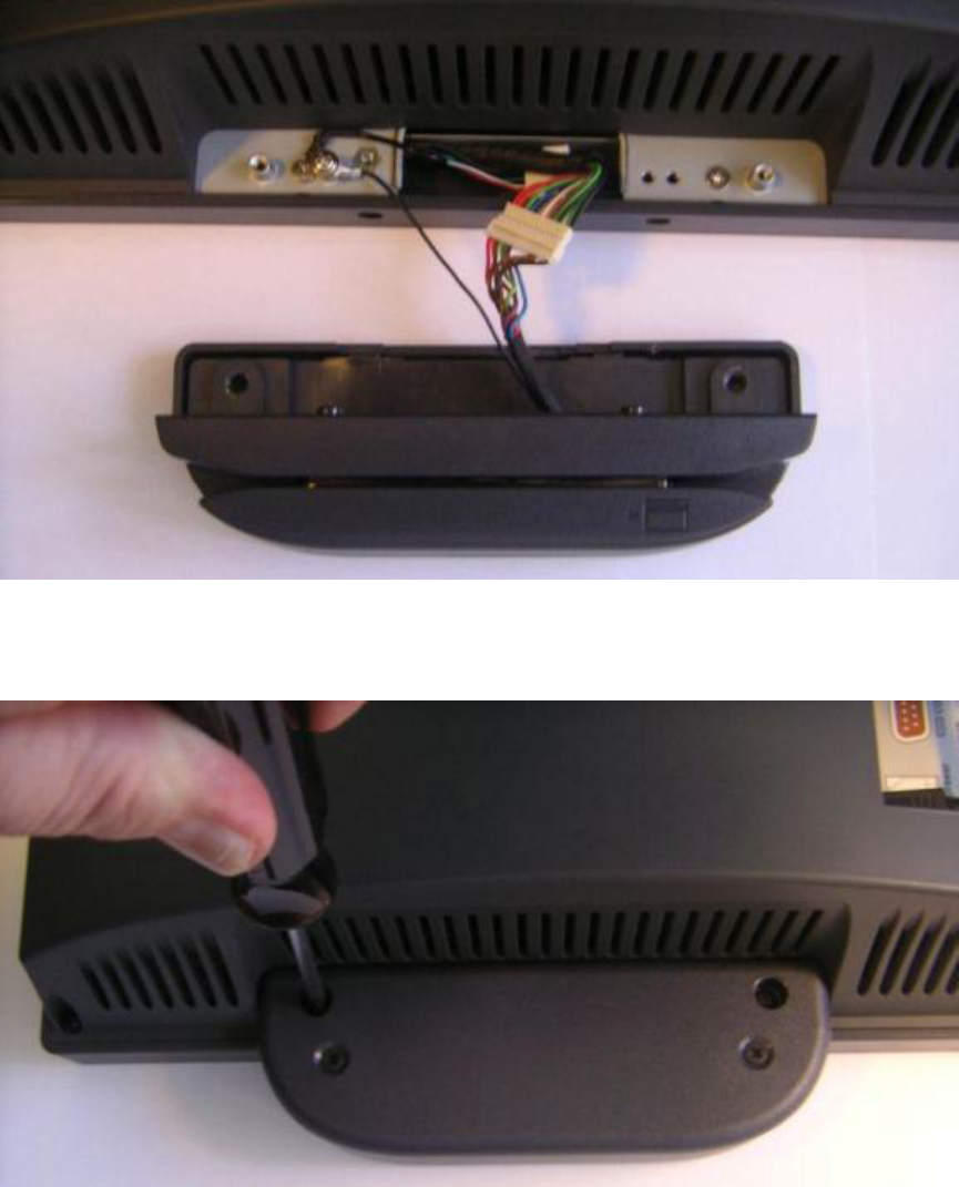
Connect the cable together as shown add secure the static ground wire with screw
provided as shown.
Attach cables
Attach the MSR using the two screws at the locations shown below.
Mounting MSR
You may now power up the 680 and the MSR should be working. For a quick test you
can open Notepad and swipe a card, the information should appear in Notepad. You can
now run the J2 MSR utility if you need any custom settings for the MSR.
J2 680 System Manual
Version 1.0 May 11, 2012
67
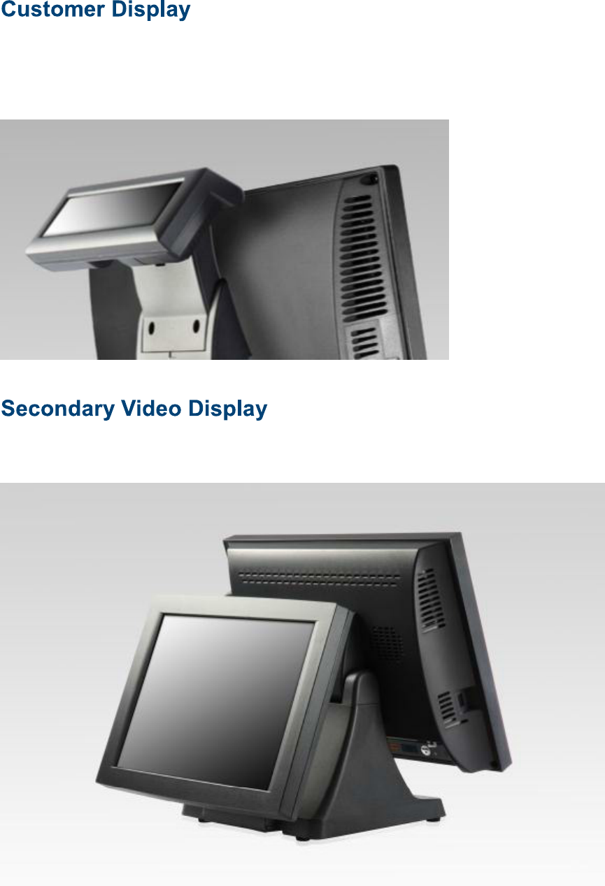
Overview
A 2 line by 20 character VFD customer side display is available optional for the J2 680.
This customer display is the same as used on the J2 580/615/625/630 POS systems.
The J2 680 has the same options as available on the J2 580/615/625/630 POS systems.
Secondary display of 10 inch, 12 inch 4:3 and 10.1 inch 16:9 displays are available.
J2 680 System Manual
Version 1.0 May 11, 2012
68
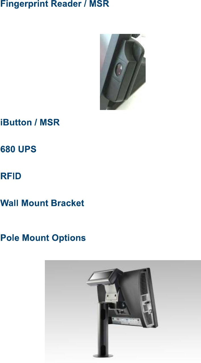
This option is the same as available on the J2 580/615/625/630 POS systems. This reader
uses the Digital Personal module.
This option is the same as available on the J2 580/615/625/630 POS systems.
Available Q2 2012
Available Q2 2012
This option is the same as available on the J2 580/615/625/630 POS systems.
This bracket can be uses when not using a VESA mount.
The J2 680 has the same options as available on the J2 580/615/625/630 POS systems.

J2 680 System Manual
Version 1.0 May 11, 2012
69
Contact Information
European Office
J2 Retail Systems Ltd.
J2 House
Clayton Road, Birchwood
Warrington WA3 6RP
United Kingdom
44 (0) 1925 817003 Phone
44 (0) 1925 811989 Fax
USA Office
J2 Retail Systems Inc.
9251 Irvine Boulevard
Irvine
CA 92618
USA
Australian Office
J2 Retail Systems Pty Ltd
Unit 6 83/85 Boundary Road
Mortdale NSW 2223
Australia
02 9584 5222 Phone
02 9584 1500 Fax
Web site
http://www.j2retailsystems.com
FCC Statement
This equipment has been tested and found to comply with the limits for a Class A digital device, pursuant to Part 15 of the
FCC Rules. These limits are designed to provide reasonable protection against harmful interference when the equipment is
operated in a commercial environment. This equipment generates, uses, and can radiate radio frequency energy and, if not
installed and used in accordance with the instruction manual, may cause harmful interference to radio communications.
Operation of this equipment in a residential area is likely to cause harmful interference in which case the user will be
required to correct the interference at his own expense.
This device complies with FCC radiation exposure limits set forth for an uncontrolled environment.
This device complies with Part 15 of the FCC Rules. Operation is subject to the following two conditions:
(1) this device may not cause harmful interference, and
(2) this device must accept any interference received, including interference that may cause undesired operation.
Caution!
Any changes or modifications not expressly approved by the party responsible for compliance could void the user's
authority to operate the equipment.