FLYTECH TECHNOLOGY J680H92 POS User Manual J2 680 System Manual 1 0
FLYTECH TECHNOLOGY CO., LTD POS J2 680 System Manual 1 0
Contents
- 1. Users Manual_Part 1
- 2. Users Manual_Part 2
Users Manual_Part 1
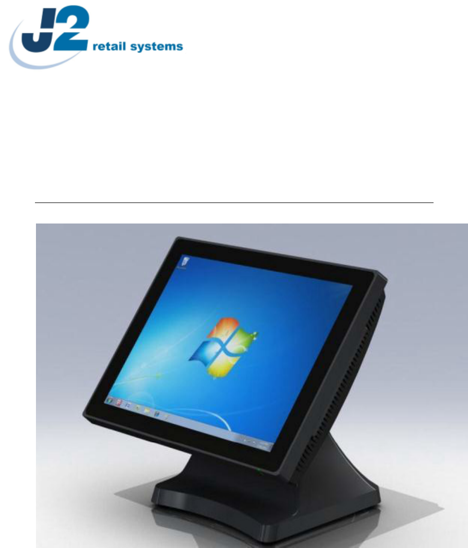
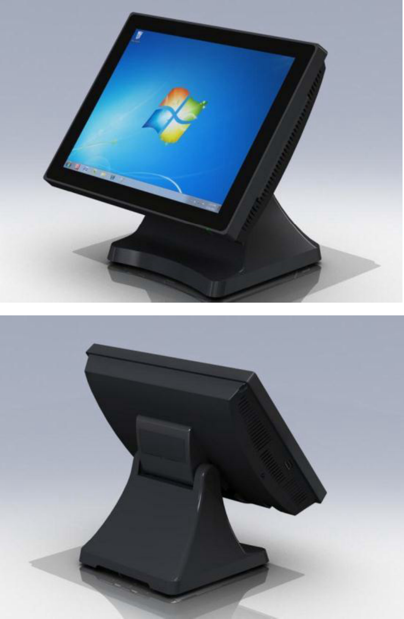
J2 680 Integrated Touchscreen Computer
System Manual
May 2012
J2 680 System Manual
Version 1.0 May 11, 2012
2
Copyright © 2011-2012 J2 Retail Systems Ltd
All rights reserved
Change history
Version 1.0 Release May 11, 2012

J2 680 System Manual
Version 1.0 May 11, 2012
3
Overview ............................................................................................................................ 6
Specification ....................................................................................................................... 8
Features ............................................................................................................................ 10
............................................................... 10
Hot Swappable RAID/ Dual Hard Drives ..................................................................... 10
PoweredUSB Ports / Power Port................................................................................... 10
UPS ............................................................................................................................... 11
Printer Power Port ......................................................................................................... 11
Cooling System ............................................................................................................. 11
Fan-Off Mode ............................................................................................................... 11
Versatility ...................................................................................................................... 11
System .............................................................................................................................. 12
Configurations ............................................................................................................... 12
Processor Support ......................................................................................................... 12
Processors currently supported on the 680 ................................................................... 13
I/O Ports ........................................................................................................................ 14
Off / On Button ............................................................................................................. 14
Hard Disks .................................................................................................................... 15
Zero Bezel Touch Screen .............................................................................................. 15
System Board ................................................................................................................ 16
LCD Display ................................................................................................................. 16
Secondary Video Port(s) ............................................................................................... 16
Serial ports .................................................................................................................... 18
PoweredUSB Ports ........................................................................................................ 19
Kensington Security Slot .............................................................................................. 20
Audio ............................................................................................................................. 21
Printer Power Port ......................................................................................................... 21
Cash Drawer Port .......................................................................................................... 22
CMOS Clear .................................................................................................................. 24
Power Supply ................................................................................................................ 24
Typical Power Consumption 680 .................................................................................. 25
Service .............................................................................................................................. 26
Removing the Head from the Base ............................................................................... 26
Removing the Power Supply ........................................................................................ 27
VESA Mounting ........................................................................................................... 28
Optional Wall Mount Bracket Installation .................................................................... 29
Removing the Back Cover ............................................................................................ 30
Changing the System Board .......................................................................................... 31
Adding Memory ............................................................................................................ 33
Changing the Processor ................................................................................................. 33
Accessing the HDD/SDD Drives .................................................................................. 34
J2 680 System Manual
Version 1.0 May 11, 2012
4
BIOS Setup ...................................................................................................................... 35
Entering the BIOS Setup ............................................................................................... 35
Main, System Overview ................................................................................................ 35
Advanced Settings ........................................................................................................ 36
Launch PXE ROM ........................................................................................................ 36
SATA Configuration ..................................................................................................... 37
Peripheral Power and LCD Brightness Configuration .................................................. 38
Power Configure Screen ............................................................................................... 39
Restore on AC Power Loss ........................................................................................... 39
Wake on LAN ............................................................................................................... 39
RTC Configuration ....................................................................................................... 39
Boot Settings ................................................................................................................. 40
Display OEM Logo ....................................................................................................... 40
Exit Options .................................................................................................................. 41
Driver Installation, Windows ......................................................................................... 42
Chipset Driver Installation ............................................................................................ 42
Graphics Driver Installation .......................................................................................... 42
Audio Driver Installation .............................................................................................. 43
LAN Driver Installation ................................................................................................ 44
Multi-Touch Projected Capacitive Touch Driver ......................................................... 47
Optional Multi-Touch Projected Capacitive Touch Driver .......................................... 49
OPOS drivers ................................................................................................................ 51
J2 Health .......................................................................................................................... 52
Installation ..................................................................................................................... 52
Tray Icon ....................................................................................................................... 52
Logging to File .............................................................................................................. 53
Registry Entries ............................................................................................................. 54
J2 Remote Monitoring Software ................................................................................... 54
SMI BIOS Info Utility .................................................................................................... 55
Installation ..................................................................................................................... 55
Operations ..................................................................................................................... 55
Cash Drawer Test Utility ................................................................................................ 56
Installation ..................................................................................................................... 56
Operation ....................................................................................................................... 56
J2 Virtual Serial Ports Drivers ...................................................................................... 57
RAID ................................................................................................................................ 58
RAID Overview ............................................................................................................ 58
AHCI ............................................................................................................................. 58
Enabling RAID in the BIOS ......................................................................................... 59
RAID Volume Creation ................................................................................................ 59
J2 680 System Manual
Version 1.0 May 11, 2012
5
F6 Installation Method .................................................................................................. 59
Installing the Intel Matrix Storage Manager Software ................................................. 60
Hot Swapping RAID 1 drives ....................................................................................... 60
Packing List ..................................................................................................................... 63
Standard Items .............................................................................................................. 63
680 Optional Peripherals ................................................................................................ 64
MSR .................................................................................................................................. 64
Overview ....................................................................................................................... 64
Installing the 680 MSR ................................................................................................. 65
Customer Display ............................................................................................................ 67
Overview ....................................................................................................................... 67
Secondary Video Display ................................................................................................ 67
Fingerprint Reader / MSR ............................................................................................. 68
iButton / MSR .................................................................................................................. 68
680 UPS ............................................................................................................................ 68
RFID ................................................................................................................................. 68
Wall Mount Bracket ....................................................................................................... 68
Pole Mount Options ........................................................................................................ 68

J2 680 System Manual
Version 1.0 May 11, 2012
6
The J2 680 is the second generation of very high performance integrated Point of Sale
computer from J2. Built on the features and capabilities for the J2 650 the J2 680 offers
even higher performance and expanded I/O. The J2 680 retains all the versatility of
previous generation system and adds Quad core processor options, expanded I/O support
with PoweredUSB, Intel remote management, HDMI video, Multi-Touch, Zero Bezel
design and retains RAID and other important feature of the previous generation.
This integrated touch screen computer like most J2 designs features an
design, which means it can be used as a counter top unit, a wall-mount or a pole-mounted
computer. In this one small package you have the highest speed available intergraded or
non-intergraded POS computer currently available.
The J2 680 comes standard with an Intel 2.4GHz Dual Core Sandy Bridge processor but
can also be order with a number of other processors including the very high end Intel i7
3.4GHz Quad Core processor. The J2 680 system board uses the Intel LGA1155 socket
and supports a wide range dual and quad core processors.
Using the Intel Sandy Bridge processor with the Q67 chipset the J2 680 uses the latest
high performance desktop solution in a very small footprint system. This solution
provides for very high performance but with a very low carbon foot print. The Sandy
bridge chipset is design only to draw as much power as need for any given operation
greatly reducing the average power consumption for this level of performance.
Designed for easy machine maintenance and upgradeability, the following is a list of
important 680 features:
1. Upgrades to the memory modules can be easily done by simply removing four
screws on the back cover.
2. A complete motherboard upgrade can be carried out in less than 1 minute.
3. The two quick change SATA hard disk drives are easily accessible, housed on
a slide-in drive bay that allows the drives to be hot swappable.
4. The footprint of the J2 680 is particularly compact making it ideal for the space
conscious retailer.
The 680 supports the standard Microsoft operating systems, Windows 7, POSReady 7,
Windows 7 Embedded, XP, POSReady 2009 and XP embedded. The 680 is equally
proficient with the many flavors of Linux.
J2 680 System Manual
Version 1.0 May 11, 2012
7
J2 680 System Manual
Version 1.0 May 11, 2012
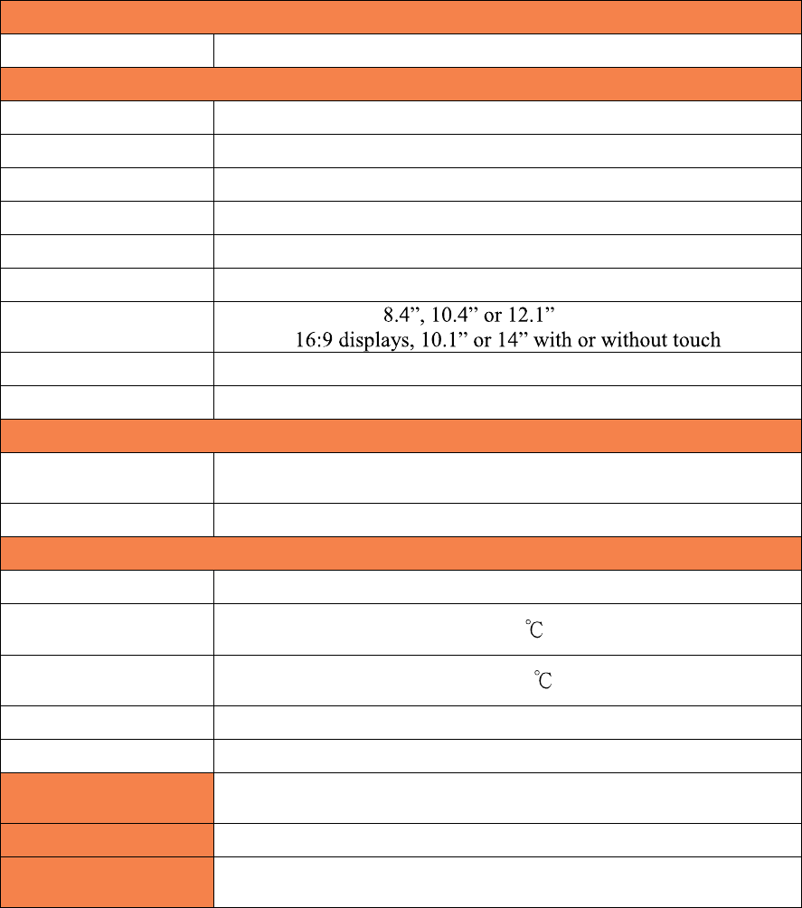
8
Main board
CPU Support
Intel
Sandy Bridge
Desktop Processors
, socket
LGA1155
Intel Celeron Dual Core G530 up to Quad Core i7- 2600 3.4GHz
Chipset Q67
System Memory 2 x 240-pin DDR3 DIMM 1333/1667MHz sockets - up to 16GB
Graphic memory Share system memory 8MB~256MB
BIOS AMI
LCD Touch Panel
LCD Size
Brightness 250 nits, adjustable in 8 steps to 25nits
Resolution 1024 x 768
Touch Screen Multi-touch Project Capacitive or True Flat Resistive 5 wire
Tilt Angle 0 ~ 90
Storage
HDD/SSD
Two 2
.5
inch
SATA
3.0 drives sup
port for HDD or SDD
RAID 0 or 1, Quick Change-hot swap
160GB HDD or 16GB SSD standard
External I/O Ports
USB 6 total 2.0, 5 in cable well, 1 on side, 3 are PoweredUSB
Serial Four DB9 RS-232 with power option
PoweredUSB 2 +12V PoweredUSB and 1 +24V PoweredUSB
LAN 10 /100/ 1000 Intel 82579LM Controller
2nd Display One VGA port and One DisplayPort
DisplayPort supports HDMI and DVI displays
Cash Drawer 2 x RJ 11 24V with status
Power In 19VDC 9.47 amps
Audio Jack One headset, one microphone-in
Printer Power +24 V 2.5 amps, supports most 24V POS printers
Power LED Front bezel, green for on, amber for standby
J2 680 System Manual
Version 1.0 May 11, 2012
9
Power
Power Adapter
19VDC, 180W, 100
-
240 VAC,50~60Hz, 2.5
A
Optional Peripheral
MSR 3 Track
iButton Dallas Key iButton
Fingerprint Reader USB Digital Persona Fingerprint Reader
RFID 125KHz RFID USB
2-in-1 MSR 3 track / Finger Print
2-in-1 MSR 3 track / iButton
Second Display
4:3
display
s,
with
or with
out touch
Customer Display 2x20 VFD
UPS DC UPS, 0.5-1.5 hours run time
Mounting
Standard
Counter Top Base, Adjustable Viewing Angle 0
-
90°
100mm VESA mounting point
Optional Pole Mount, Adjustable angle VESA, Swing-arm Mounts, others
Environment
EMC & Safety FCC, Class A, CE, LVD
Operating
Temperature 0 ~ 40
Storage
Temperature -20 ~ 55
Operating Humidity 20% ~ 80% RH non-condensing
Storage Humidity 20% ~ 85% RH non-condensing
Dimensions
(W x D x H)
370 x 250 x325mm
Weight 8.1kg
OS Support Windows 7, POSReady 7, Windows 7 Embedded, XP,
POSReady 2009, XP Embedded, version of Linux
* This specification is subject to change without prior notice.
J2 680 System Manual
Version 1.0 May 11, 2012
10
LGA 1155
By using the latest desktop processors and chipsets, code named
Sandy Bridge, the J2 680 supports a very wide range of processors. By taking advantage
of J2 , and POS
computer designs, we are able to combine features of all three for an optimal POS system
design. The result is a POS system that can utilize a desktop chipset that draws very little
power and generates a low amount of heat, similar to mobile chipsets and processors.
Notebook quality components are used in the processor, chipset, and power supply
circuit, which allows for reduced heat generation and minimal power usage.
Additionally, the 680 takes full advantage of the low power features built into the Intel
processor and chipset to further reduce heat.
Hot Swappable RAID/ Dual Hard Drives
Like the J2 650, the first integrated POS system on the market to offer a hot swappable
RAID feature the J2 680 also supports this feature. The two internal 2.5 inch SATA hard
drives can be configured as a RAID array which gives true fault tolerance to the hard
drive subsystem.
PoweredUSB Ports / Power Port
Addressing the need for additional power ports the J2 680 supports two +12V and one
+24V PoweredUSB ports. The J2 680 can take advantage of growing availably or
PoweredUSB products on the market.
In addition to the three PoweredUSB port the J2 680 also support four powered serial
ports, and VGA +12V power, a +24V printer power port and 3 standard 2.0 USB ports.
By using a combination of these powered ports most all additional external power
supplies for devices like
display and other can be eliminated. This save space and reduces cost, cables and
powered consumption. Also in most installs this means only one AC power point is
needed. In additional with J2 optional UPS all these devices will be powered during a
power outage.
J2 680 System Manual
Version 1.0 May 11, 2012
11
UPS
Not your ordinary UPS, the J2 680 UPS is a DC, not an AC UPS. The UPS fits
conveniently into the base of the unit. Unlike an AC UPS the J2 UPS makes the 680 work
more like a notebook computer. In addition to running the 680 for up one hour, the UPS
will run all the POS peripherals attached to the 680, including the printer. Because of the
unique design of the J2 UPS and power supply, the need for special AC power
conditioning devices is eliminated.
Printer Power Port
The 24 volt Printer Power Port can power most POS printers on the market, including the
popular Epson line of printers. When used along with the J2 UPS, if a power outage
should occur, the POS terminal can still operate and print receipts for up to one hour.
Also, when the 680 is turned off the printer is turned off also. This is very useful when
the auto power on and off features of the 680 is used. This also applies to the +24V
PoweredUSB port (note, only one +24V port can be used at a time).
Cooling System
Great attention was paid to the thermal solution of the 680, it is truly a unique feature.
The 680 can run as a fan less or fan-cooled system. Because of the very wide range of
processors supported, thermal loads can range from 5 watts to as high as 95 watts. The
680 was designed to handle these thermal loads while still being super quiet. Two smart
fans are used in conjunction with an Embedded Controller (EC) to ensure that the fans
run at the lowest possible speed while still providing proper cooling. Fan speed changes
are controlled to produce the smallest acoustical signature possible. The 680 fans are the
type used in Blade Servers and have a speed range from 3500~10,000 rpms at very high
torque.
Fan-Off Mode
When using the i5 or lower performance processor the 680 can run in a fan-off
configuration. In the mode the 680 is a fan-less convection cooled device. This fan less
operation may be required for high dust or other special environments.
This feature is uniq
-
Versatility
The word versatility is very much over used, but it is the correct word to describe the
most unique feature of the 680. The combination of all the 680 unique features allows for
the 680 to fit many roles. The 680 is not just one product, but a full product range all in
one system. From fan less thin client to Quad Core RAID Server - the 680 does it all.
J2 680 System Manual
Version 1.0 May 11, 2012
12
Configurations
The 680 can be ordered or upgraded to many possible configurations. Selecting the right
combination of memory, processor, hard or solid state drive(s), and software drivers can
dramatically change the performance of the 680 system. For a lot of users the standard
530 2.4GHz dual core processor and 2GB of memory is fine, as this is already more
powerful most all POS systems, but some applications may require more horse power. In
this case the J2 680 could be configured with a quad core i5 or i7 processor.
J2 will be happy to help you determine what you may require from the 680 in the most
cost effective way. More memory may be added to get the performance needed, or
sometimes a quad core processor and dual HDD with RAID are needed. The 680 can do
it all, low end to high end.
Processor Support
The 680 supports a very wide range of Intel processors. Each provides a different price
performance level. From Celeron dual core, Pentium dual core and -3, i5 and i7 dual a
quad core with processor speeds from 2.4GHz to 3.4GHz are all supported by the 680.
The 680 comes standard with the Intel dual core 2.4 GHz G530 processor but can be
ordered with a different processor type. The processor can be easily upgraded by a
qualified technician. The 680 uses the Intel defined LGA1155 socket. Intel is constantly
adding new processors so please check with J2 for any additions since publication of this
manual.
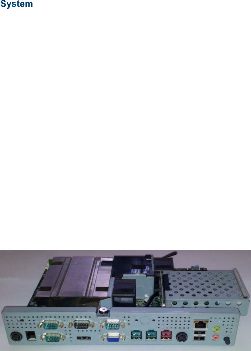
The large heat sink, cooling fans, and fan controller (shown below) are designed to keep
everything running cool, quiet, and reliably with the supported processors.
System Board, back view
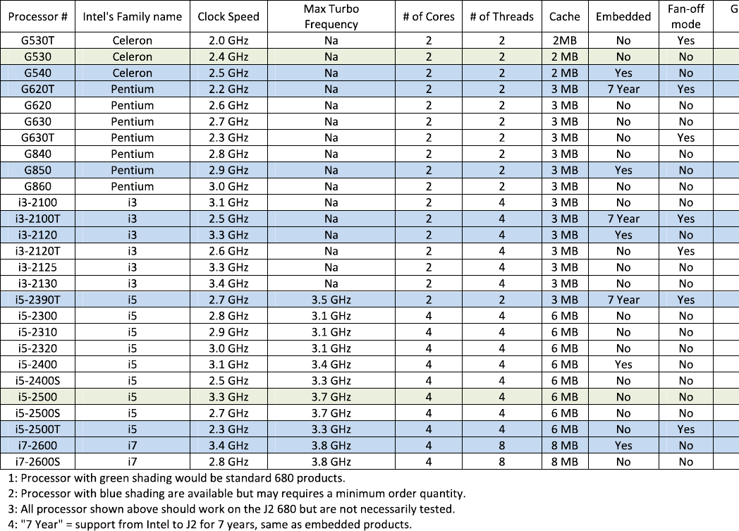
Processors currently supported on the 680
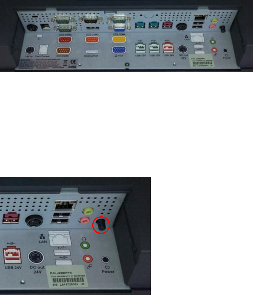
I/O Ports
Most I/O ports are accessible in the cable well at the bottom of the unit. A cover plate is
provided to cover the cables.
I/O Panel
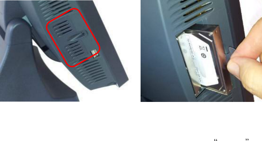
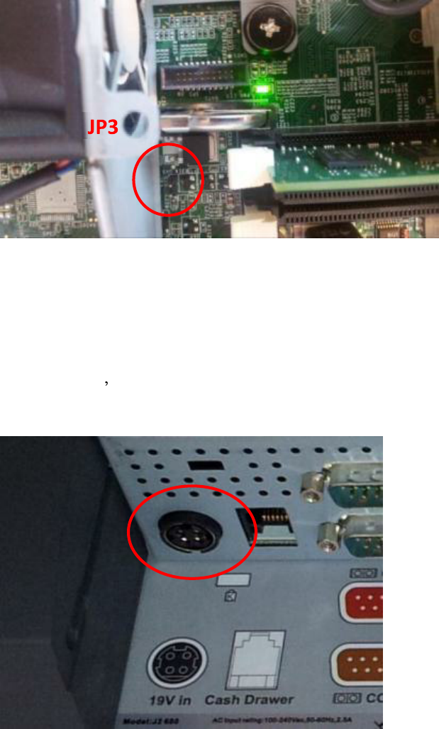
Off / On Button
The Off /On button is located in the cable well, as shown. This button is located near the
side to prevent accidental powering down by the user. The function of the button can be
controlled by the OS. If the 680 hangs for some reason it can always be powered off by
holding the Off / On button in for six seconds.
The 680 also supports the following: Restore on AC on power loss, Wake On LAN, and
Wake On RTC alarm features to control the system power up.
Off / On button Location
J2 680 System Manual
Version 1.0 May 11, 2012
15
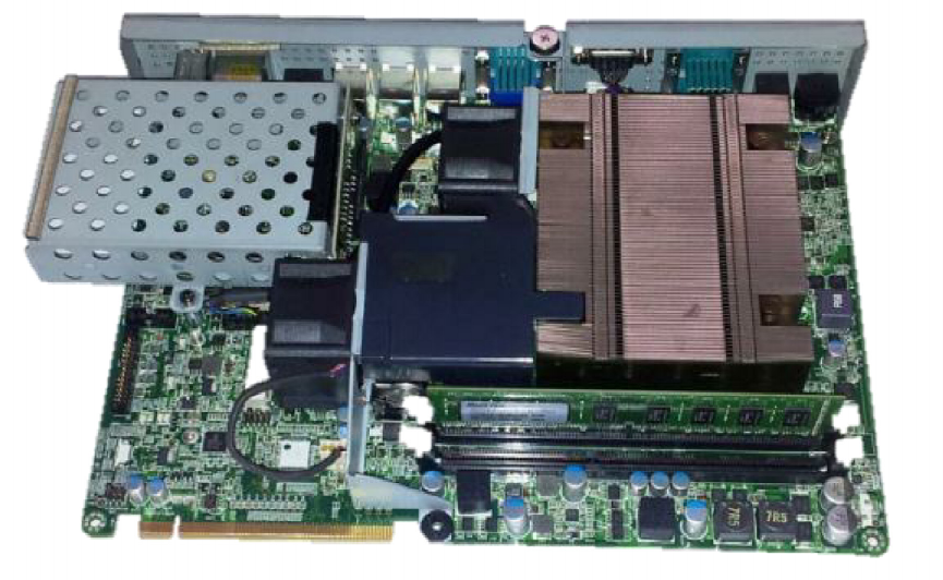
Hard Disks
Two 2.5 inch SATA hard drives (HDD) or solid state drives (SSD) are supported. These
drives can be configured as standard hard drives or as a RAID array. The SATA interface
can support data transfer rates up to 6.0 Gb/s and supports AHCI and Hot Swapping of
hard drives.
The HDDs can easily be accessed by removing a panel on the left side of the unit. HDDs
can be installed or removed in seconds by removing one screw. A carrying tray (two of
which are supplied with the 680) fits onto a new drive without tools. The drive can now
easily be slid into the drive bay. In a RAID 1 configuration a drive can be hot swapped,
removed, or inserted with the power on (see section on RAID setup).
HDD access panel
HDD slide in
-
slide out drive bay
Zero Bezel Touch Screen
The 680PTC unit uses a Multi-Touch Projected Capacitive technology touch screen
(PCT). The PCT touch screen has no known failure mode-- it does not wear out. This
screen is made with tempered glass and does not reduce the brightness of the LCD panel.
When operating in a very high use environment PCT is the recommended touch screen
technology. The PCT touch screen will work with most gloves and stylus designed to
work with tablet computers. The screen has a smooth glass surface that is reflective.
The 680TFR uses a five-wire touch screen rated at 35 million touches per point. The
resistive technology is very responsive and is the traditional choice for a hospitality POS
system. The screen has an anti-reflective plastic film surface.
Both screens are fully spill proof, dust proof and can be cleared with and standard glass
cleaner. The zero bezel, sometimes called true flat, design allow for this plus easy
cleaning. The 680 touch screen was designed to easily be changed, normally in less than
two minutes. Depending on operating environment and usage, both the Resistive and
PCT touch screens have strengths and weaknesses. J2 offers both touch screen
technologies on the 680.
J2 680 System Manual
Version 1.0 May 11, 2012
16
System Board
POS computers typically have a desired lifespan of 10 years or longer, therefore product
quality is of the utmost importance. The 680 electronics are built with high-end
components to ensure reliability and long lasting product performance.
The system board is designed for quick replacement and only has one connection, an
edge pin connector, to which all motherboard connections are made.
System board
LCD Display
The LCD display for the 680 is a 1024 x 768 resolution display with 16.2 Million colors.
The brightness is rated at 250cd/m2. The Intel controller allows for the display to be
rotated to 0, 90, 180 or 270 degrees without loss of performance.
The LCD brightness can be controlled in 8 steps, from 250 cd/m2 to 25 cd/m2. The
brightness can be set to a fixed level in the BIOS or controlled by a utility supplied by J2.
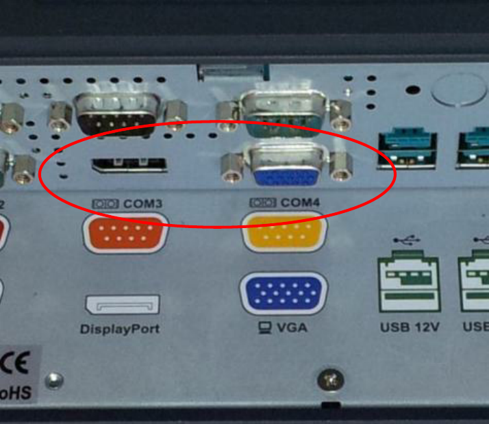
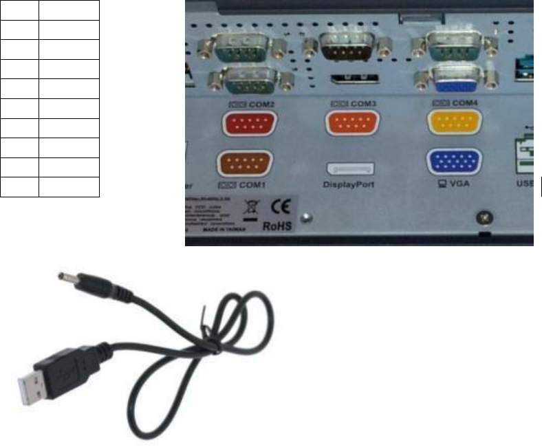
Secondary Video Port(s)
A standard PC VGA video port is supported on the 680 and can be set as the primary or
secondary display The VGA video port has an industry standard HD DB15 connector.
When used with some J2 monitors the display can be powered by the 680 through this
connector.
J2 680 System Manual
Version 1.0 May 11, 2012
17
The 680 also supports the newer digital video standard DisplayPort connector. This
connector supports a DisplayPort monitor or a HDMI display or DVI monitor. When
used with HMDI or DVI display a passive adapter cable is used. When used with a
HDMI display Audio is support via the same HMDI cable.
The secondary video displays can be configured as a Twin, Intel Dual Display Clone, or
Extended Desktop. Most all monitor resolutions from 640 x 480 to 2560 x 2048 are
supported.
Note that only one external video display is support at a time, either on the VGA video
port or the DisplayPort video port.
VGA and DisplayPort Video Ports
J2 680 System Manual
Version 1.0 May 11, 2012
18
Serial ports
The 680 has four external RS232 serial ports, all of which can be powered. The serial
ports are standard RS-232 ports with a DB9 male connector. The serial ports, in a normal
configuration, are mapped to COM 1-4.
There also four internal serial ports one of which is used for the resistive touch controller
and the other are reserved for other internal options.
COM ports 1-4 can supply power to an external device when required, like the optional
J2 Customer Display. COM 1 can supply +5 volt and COM 2-4 supply +12 volts. The
voltage is supplied on pin 9 (RI) of the DB9 connector. The maximum current is 1000ma
and is over-current protected. A BIOS setting is used to enable the voltage on each port.
J2 does not normally recommend using the +5 volt option on COM 1 and is only there for
some legacy devices. The problem is it easy for +5 volt device to be plugged into a +12
enable serial port by mistake which will burn out the +5 volt device. A good alternative
to powering a +5 volt serial device, or any +5V device would be to use power from an
unused USB port. Cables for this are readily available (see below).
DB9 pin out serial ports Serial Port
Pin
RS232
1 DCD
2 RD
3 TD
4 DTR
5 GND
6 DSR
7 RTS
8 CTS
9 RI
USB to +5V cable
J2 680 System Manual
Version 1.0 May 11, 2012
19
USB Ports
The 680 has six external and 4 internal USB 2.0 ports. Of the six external ports (see
below) five ports are located in the cable well and one is located on the left side of the
unit for easy access. The four internal USB ports are as follows: one can be used for the
optional Finger Print Reader and is located on the MSR connecting point. The second
internal USB port is used for the PCT touch screen controller and the other internal USB
ports is designed for other optional internal devices. All the J2 680 USB ports can supply
1000ma of power, 500ma more than the normal for the USB specification.
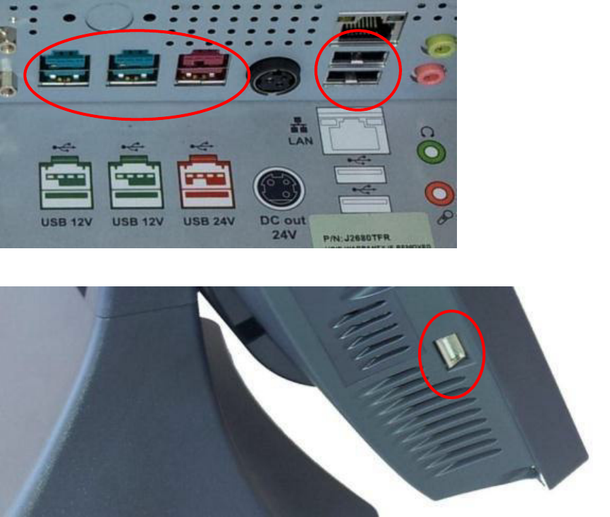
PoweredUSB Ports
Of the 6 external USB 2.0 ports 3 are PoweredUSB ports. Located in the cable well are
two +12V PoweredUSB ports and one +24V PoweredUSB port. These ports conform to
the PoweredUSB standard.
It should be noted that these three ports can also be used as standard USB ports as well.
Normal +5 USB devices will plug into the bottom half of the connector without a
problem.
USB Ports
Side USB Port
J2 680 System Manual
Version 1.0 May 11, 2012
20
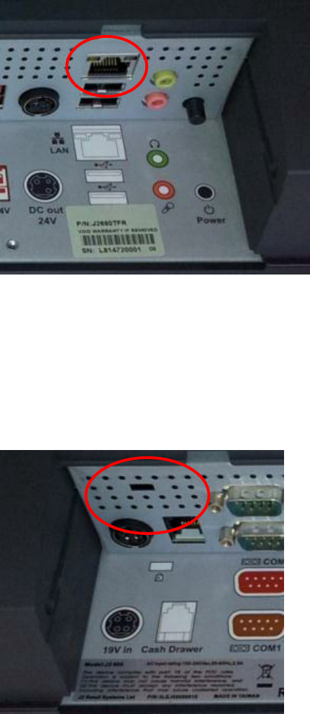
Ethernet Connection
The 680 uses the Intel 82579LM Gigabit Ethernet controller. The Ethernet connector is
located in the cable well, as shown below. The Ethernet controller supports Wake on
LAN, the BIOS supports a PXE boot ROM as well. There are two LEDs on the LAN
connector: the Green LED lights up when the LINK signal is present and the Amber
LED lights comes on when there is LAN activity. This Ethernet supports Intel AMT
feature when used with the correct processor.
Ethernet Connector
Kensington Security Slot
There is a Kensington Security Slot (lock slot) on the 680. (Please see below).
It is located on the head in the cable well. The Kensington locks are normally used as a
deterrent to prevent opportunistic theft. Most retail locks will work with the 680, however
please check to see if a lock fits, as not all do.
Kensington slot Cable Well
J2 680 System Manual
Version 1.0 May 11, 2012
21
Audio
The 680 uses the VIA1708B HD audio controller. There is one internal speaker.
Both a microphone jack and a headset jack are located in the cable well of the 680, as
seen below, which allows for the connection of a microphone and headset or audio out to
other devices. Audio is also output via the HDMI port when used.
Audio Jack Location
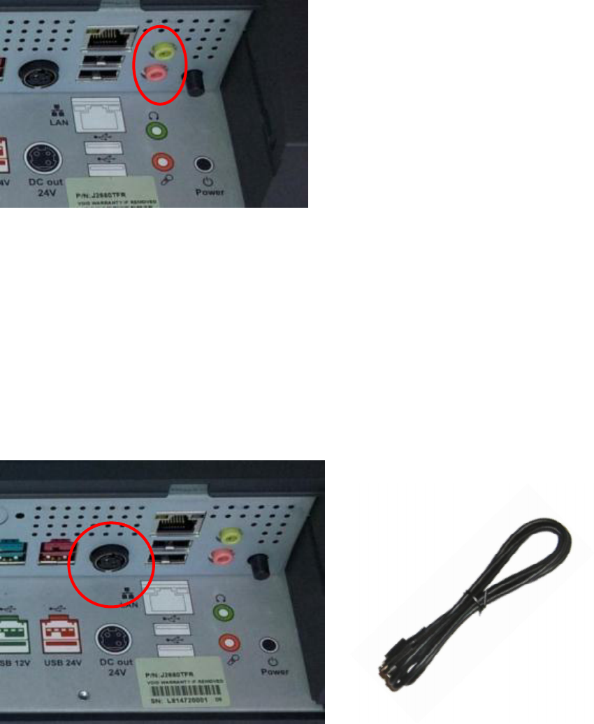
Printer Power Port
The Printer Power Port allows an industry standard POS printer to be powered from the
680 and eliminates the need for a separate external power supply for the printer.
The Printer Power Port supplies 24 VDC 2.5 amps and 6.0 amp surge current which will
run most POS printers on the market. The power cable for this port is supplied standard
with the 680 unit. The Printer Power Port will also supply power to a printer even when
running on the optional UPS. When the 680 is powered down, then power to the printer is
turned off. This same power circuit is used by the +24 PoweredUSB port and normally
only one +24V device is supported at one time.
Printer Power Port Printer Power Port Cable
J2 680 System Manual
Version 1.0 May 11, 2012
22
6
1
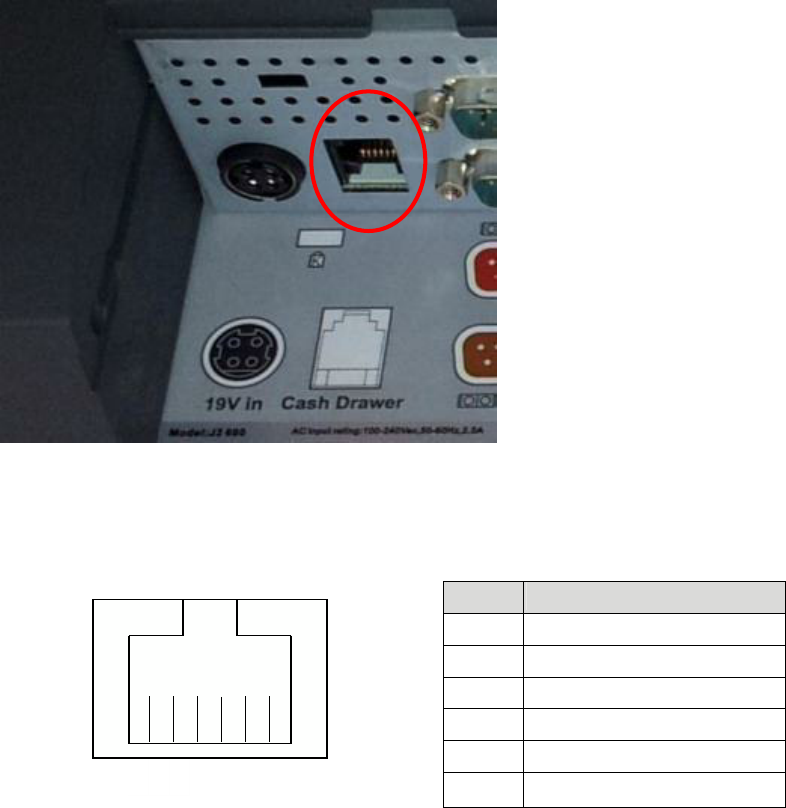
Cash Drawer Port
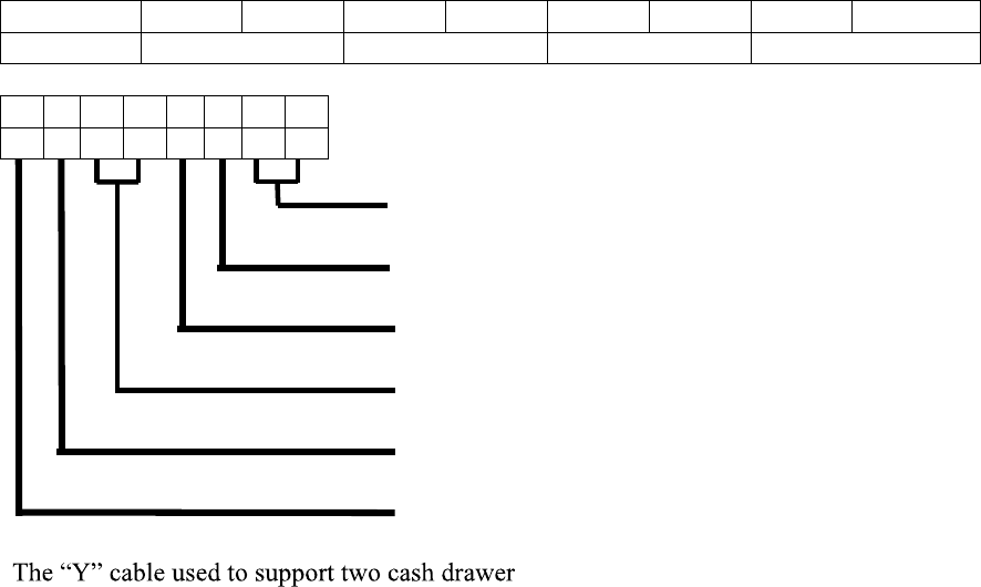
The 680 is equipped with one Cash Drawer port that will support one or two drawers.
This port is located in the cable well and uses the industry standard RJ-11 connector and
pin out (illustrated below). This pin-out is the same as used by EPSON printers and
cables for the EPSON printer normally work with the 680.
Cash Drawer Ports
Cash Drawer 1 Pin Assignment
Pin Signal
1 GND
2 CD1 SOLENOID
3 STATUS / STATUS CD1
4 24V
5 CD2 SOLENOID
6 GND / STATUS CD2
The application may address the Cash Drawer port in two ways:
1) Using the J2-supplied OPOS drivers for Windows.
2) Direct access to the I/O ports
3) J2 supplied Virtual Serial Cash Drawer Emulator
J2 680 System Manual
Version 1.0 May 11, 2012
23
Cash Drawer Controller Register
The Cash Drawer Controller use one I/O address to control the Cash Drawer.
Register Location:
48Ch
Attribute:
Read / Write
Size:
8bit
BIT
BIT7
BIT6
BIT5
BIT4
BIT3
BIT2
BIT1
BIT0
Attri
bute
Read
Reserved
Write
Reserved
7
6
5
4
3
2
1
0
X
X
X
X
X
Reserved
Cash Drawer 1 fire
Cash Drawer 2 fire
Reserved
Cash Drawer 1 status
Reserved
s on the one RJ-11 is the same as is used
on Epson printers.
J2 680 System Manual
Version 1.0 May 11, 2012
24
CMOS Clear
The 680 CMOS can be cleared jumping JP3 pin 1-2 then removing the jumper.
Power Supply
The 680 uses a notebook type power supply that is normally mounted in the base of the
unit. The power supply is rated with an output of 180 watts 19 VDC 9.47 Amps and has
an input rating of 100-240VAC at 50~60Hz 2.5Amps maximum. The power supply has
an efficiency rating IV. The power supply connector is a four pin locking type that plugs
into the system s power input connector located in the cable well.
Power Input connector

J2 680 System Manual
Version 1.0 May 11, 2012
25
Typical Power Consumption 680
The typical power consumption of the 680 is lower that most desktop computers. Using
the latest ssors and chipset allows for much lower
power consumption than previous generations of POS computer. This when coupled with
proper system configuration can greatly reduce the systems total carbon foot print.
Test conditions
Voltage: 220VAC 50Hz, measured voltage 236 VAC
OS: POSReady 7
Heavy Load Program: PassMark BurnInTest defaults values
Maximum load: PassMark BurnInTest Max CPU Temp
Temperature: 26c
All system where tested in there standard hard drive configuration. Results are +/- 15%.
J2 680 G850 2.9GHz Pentium
1: Normal application including most POS software 40 watts
2: Very heavy load application 57 watts
3: Maximum load 64 watts
4: Normal POS app, back light off 20 watts
5: Standby, unit off, waiting for wake on LAN, RTC or power button >4 watts
J2 680 System Manual
Version 1.0 May 11, 2012
26
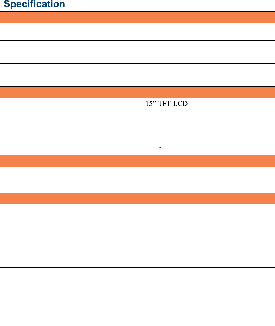
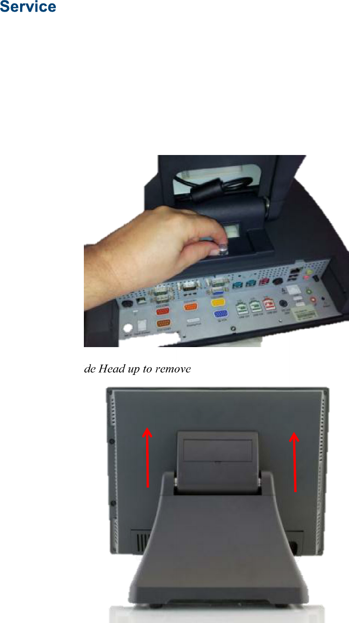
Removing the Head from the Base
The 680 is shipped with a counter top base which allows for the head to be adjusted from
0-90°.
To remove the integrated head from the base, fully loosen the thumbscrew located on the
back of the unit under the hinge of the counter top base, as shown below. Then lift the
head as illustrated:
Loosen Thumb Screw
Slide Head up to remove
J2 680 System Manual
Version 1.0 May 11, 2012
27
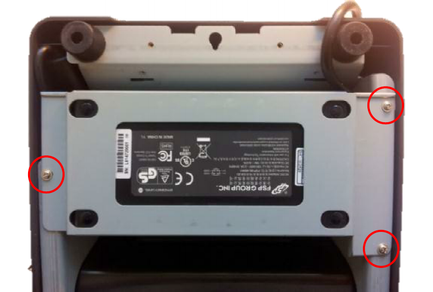
Removing the Power Supply
The power supply is normally located in the counter top base. When using a wall mount
bracket or the J2 UPS, the power supply would be external from the unit.
To remove the power supply from the base, three screws needs to be removed as shown.
Screw locations
J2 680 System Manual
Version 1.0 May 11, 2012
28
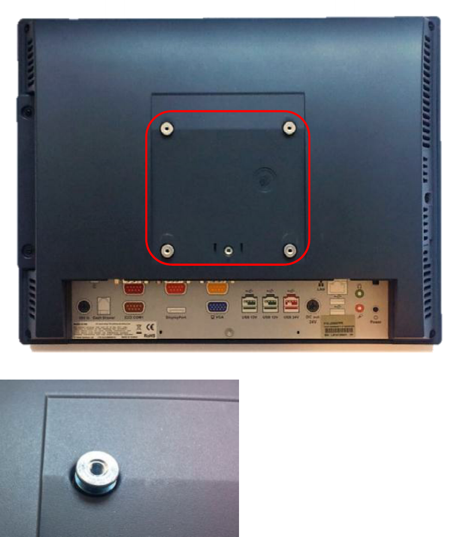
VESA Mounting
The 680 unit also supports the industry standard 100mm VESA mounting. The same
mounting hard point used for the counter top base is used for VESA mounting. The four
point that thread holes for 4mm screws.
100mm VESA Pattern
Threaded Mounting point(s), 4mm screw
J2 680 System Manual
Version 1.0 May 11, 2012
29
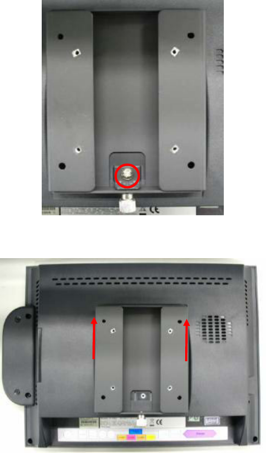
Optional Wall Mount Bracket Installation
The wall mount bracket has threaded mounting holes (screws provided) for the 75mm
VESA standard; and unthreaded holes for the 100mm standard.
Using the 100mm hole pattern the bracket can be used by itself as a wall mount bracket.
After installing the thumbscrew clip mount bracket to the wall, hang the J2 680 on the
bracket.
Install screw to secure thumbscrew clip
The bracket slides on to the J2 680 mount posts, as shown. Normally the bracket would
already be mounted to the wall or a VESA mount and the 680 would be hung on the
bracket. Once in place the thumb screw would be tightened.
J2 680 System Manual
Version 1.0 May 11, 2012
30
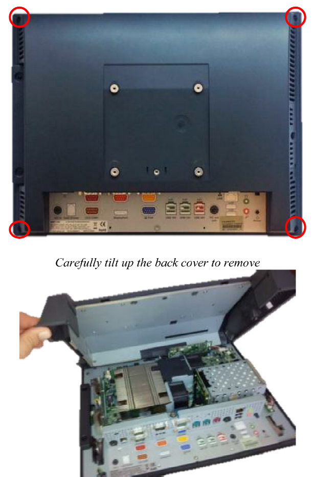
Removing the Back Cover
The following steps show how to disassemble the 680 for servicing:
On a clean, protected surface, place the unit screen-side down. Remove the four cover
screws as shown. Carefully lift the back cover as shown.
Remove four screws where
shown
Carefully tilt up the back cover to remove
Note: The 680 was designed so that the internals of the unit could be accessed without
having to remove the mounting base or the mounting bracket of the unit.