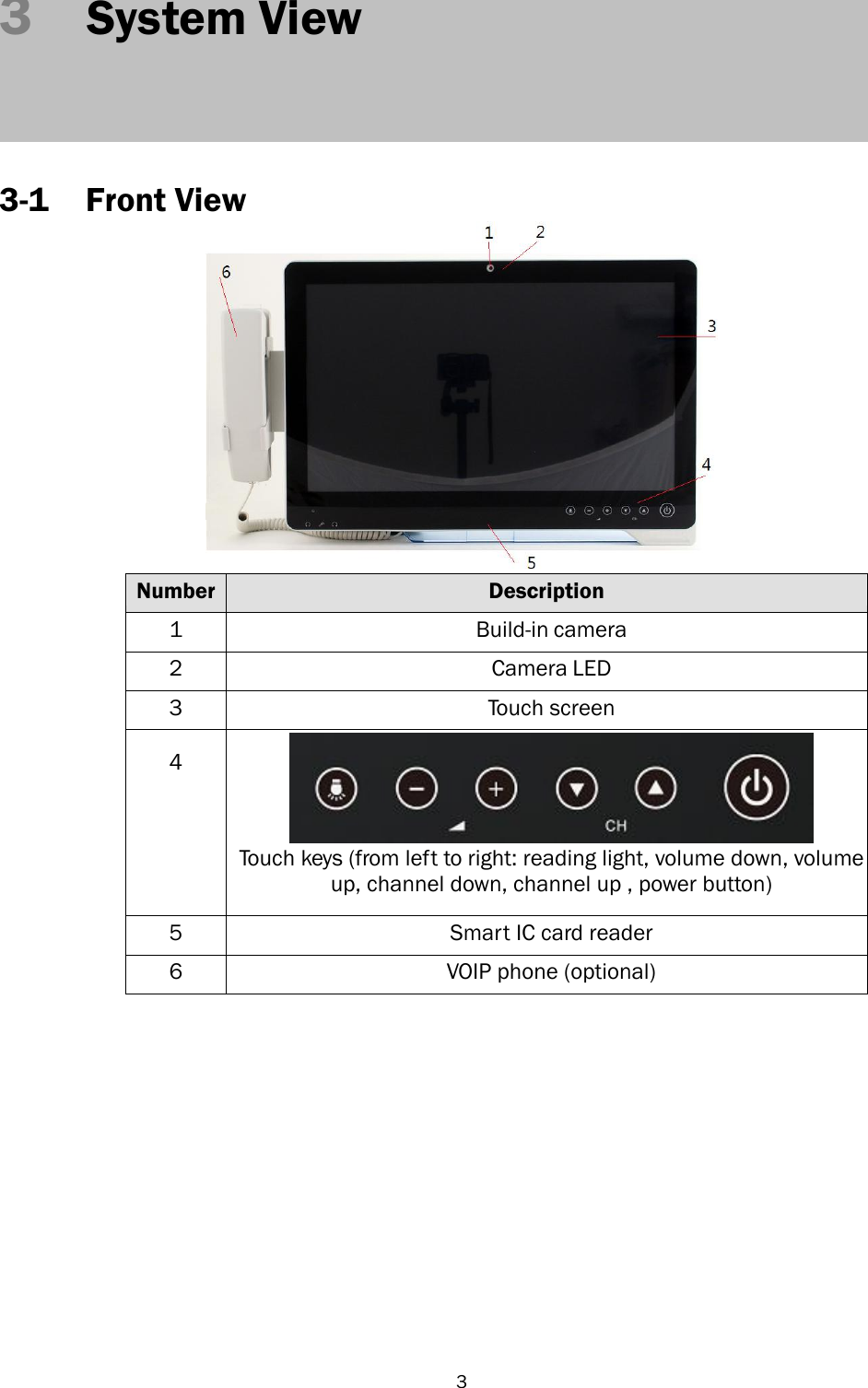
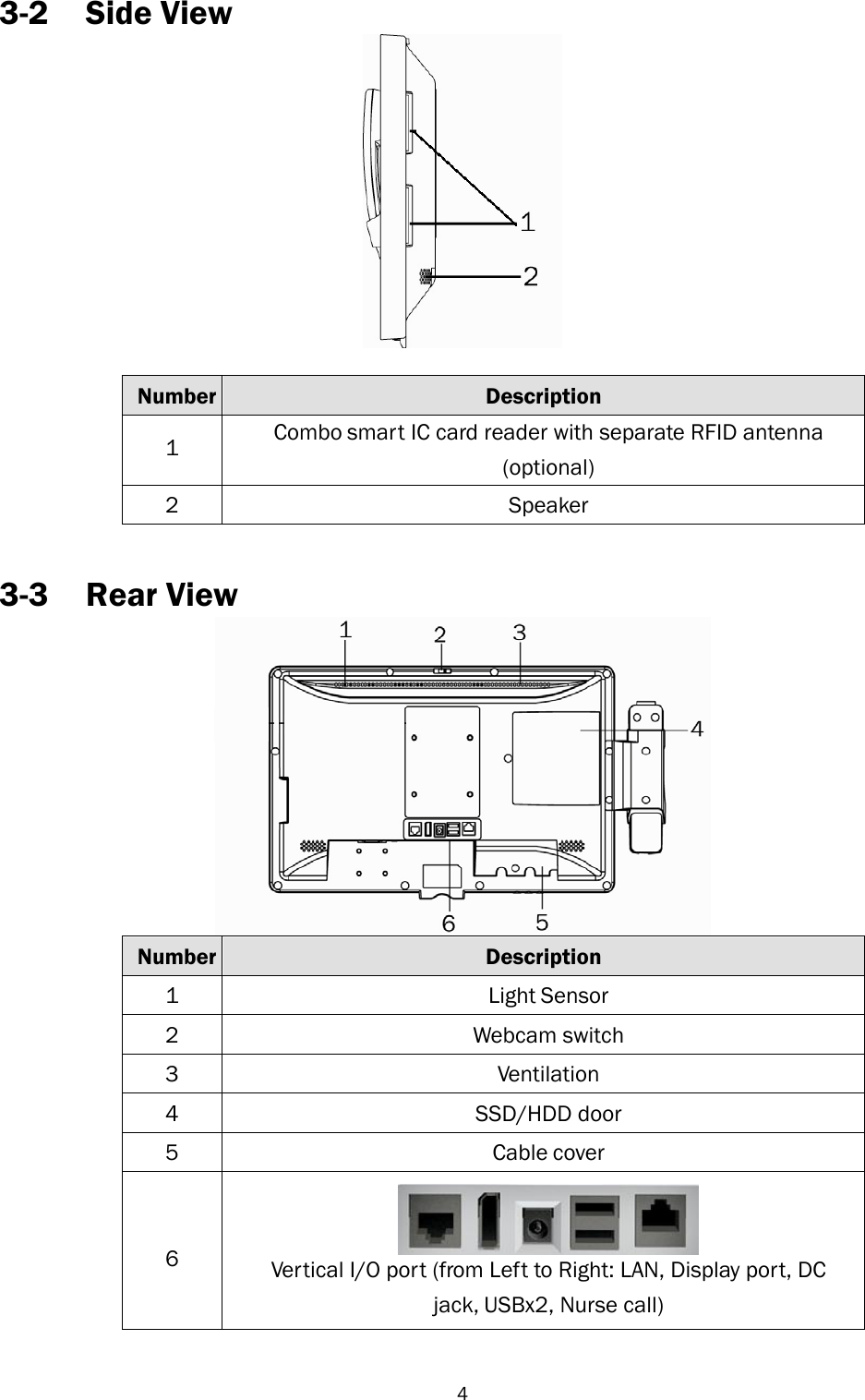
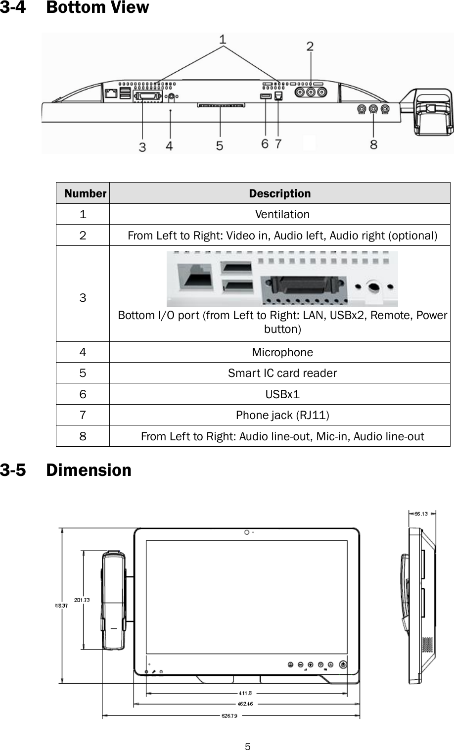
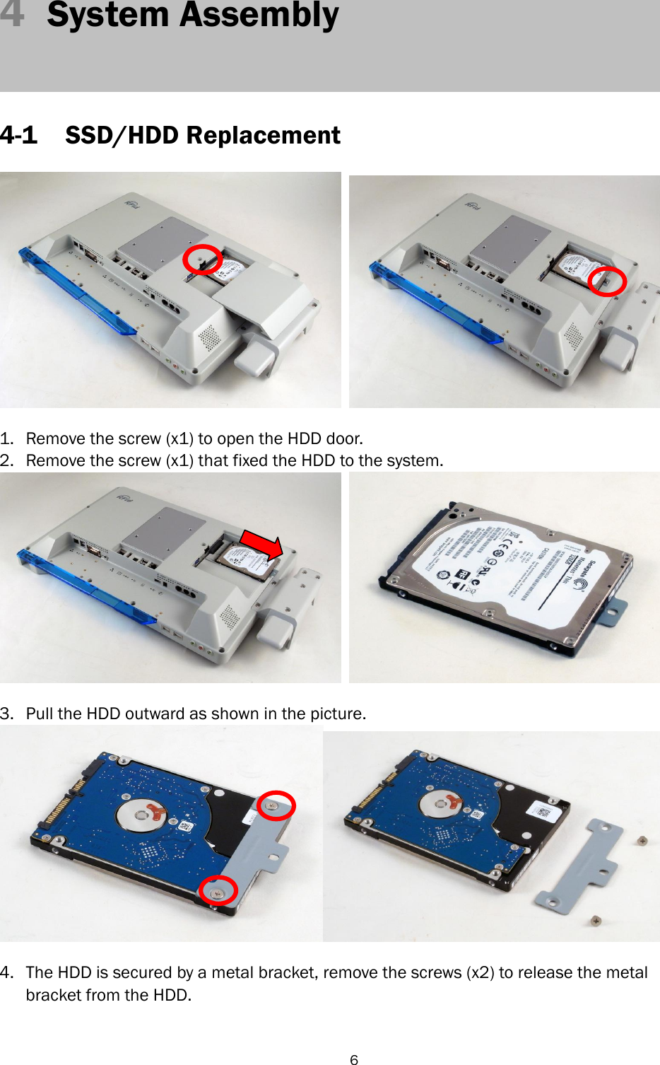
FLYTECH TECHNOLOGY K948D35 Panel PC User Manual
FLYTECH TECHNOLOGY CO., LTD Panel PC
UserManual.wiki
>
FLYTECH TECHNOLOGY
>
K948D35 User Manual
User manual
Navigation menu
Upload a User Manual
Namespaces
Wiki Guide
HTML
PDF
Info
Views
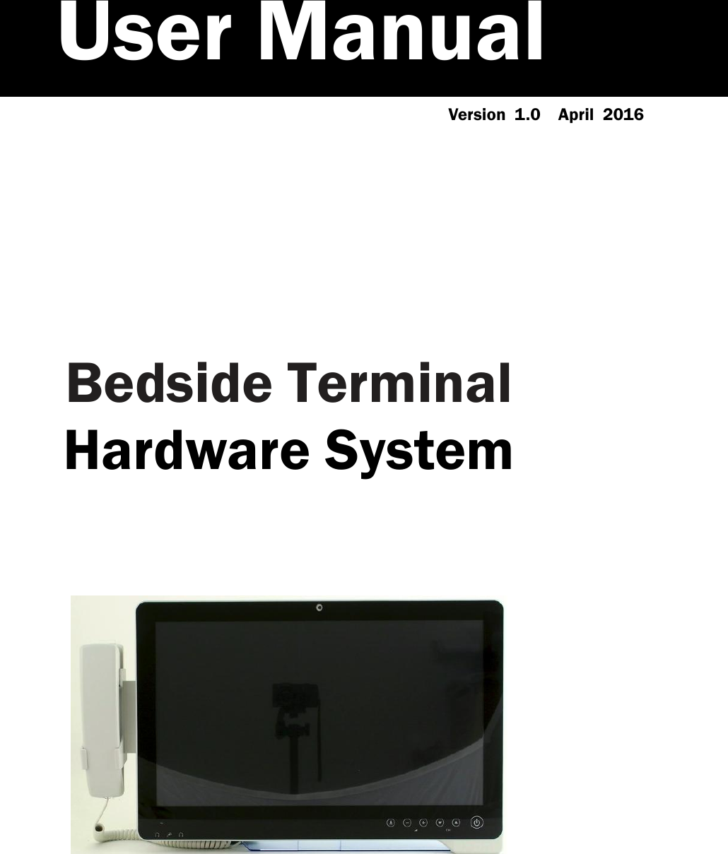
User Manual
Discussion / Help
Navigation