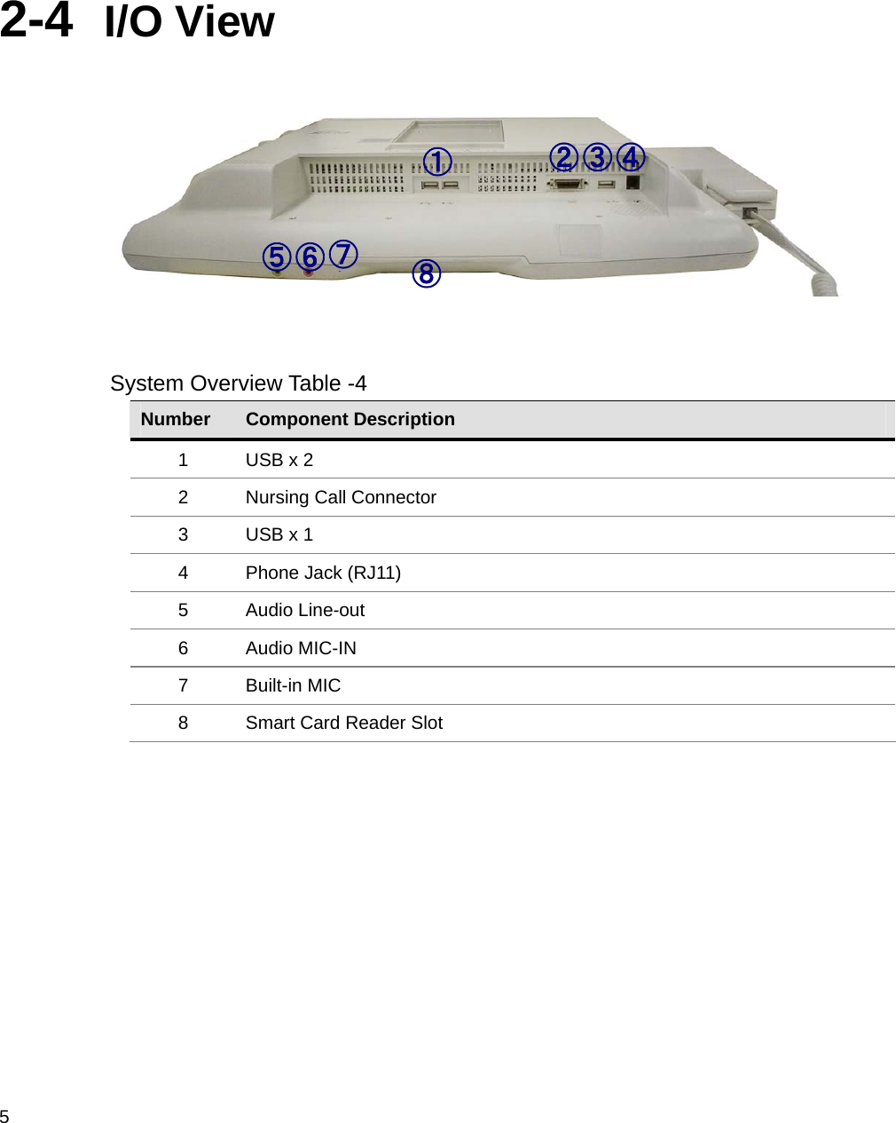
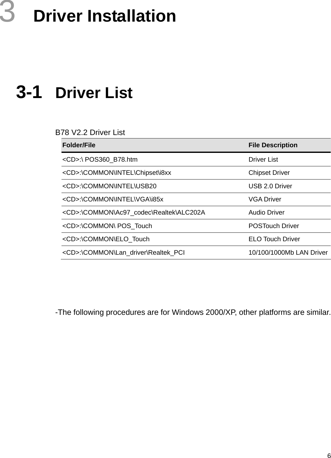
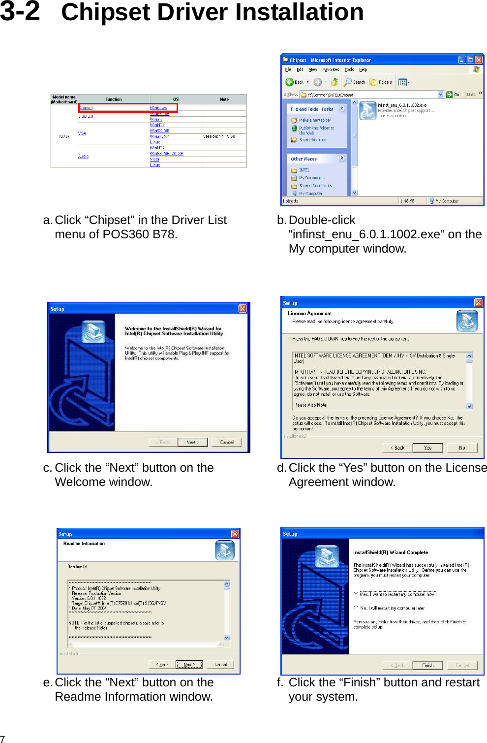
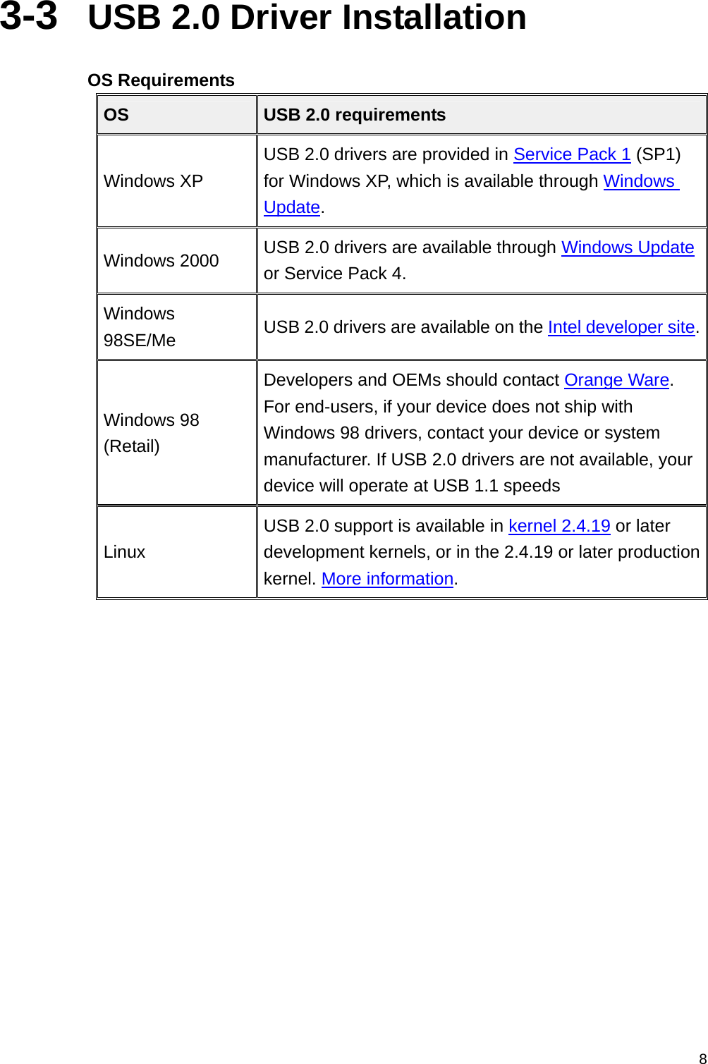
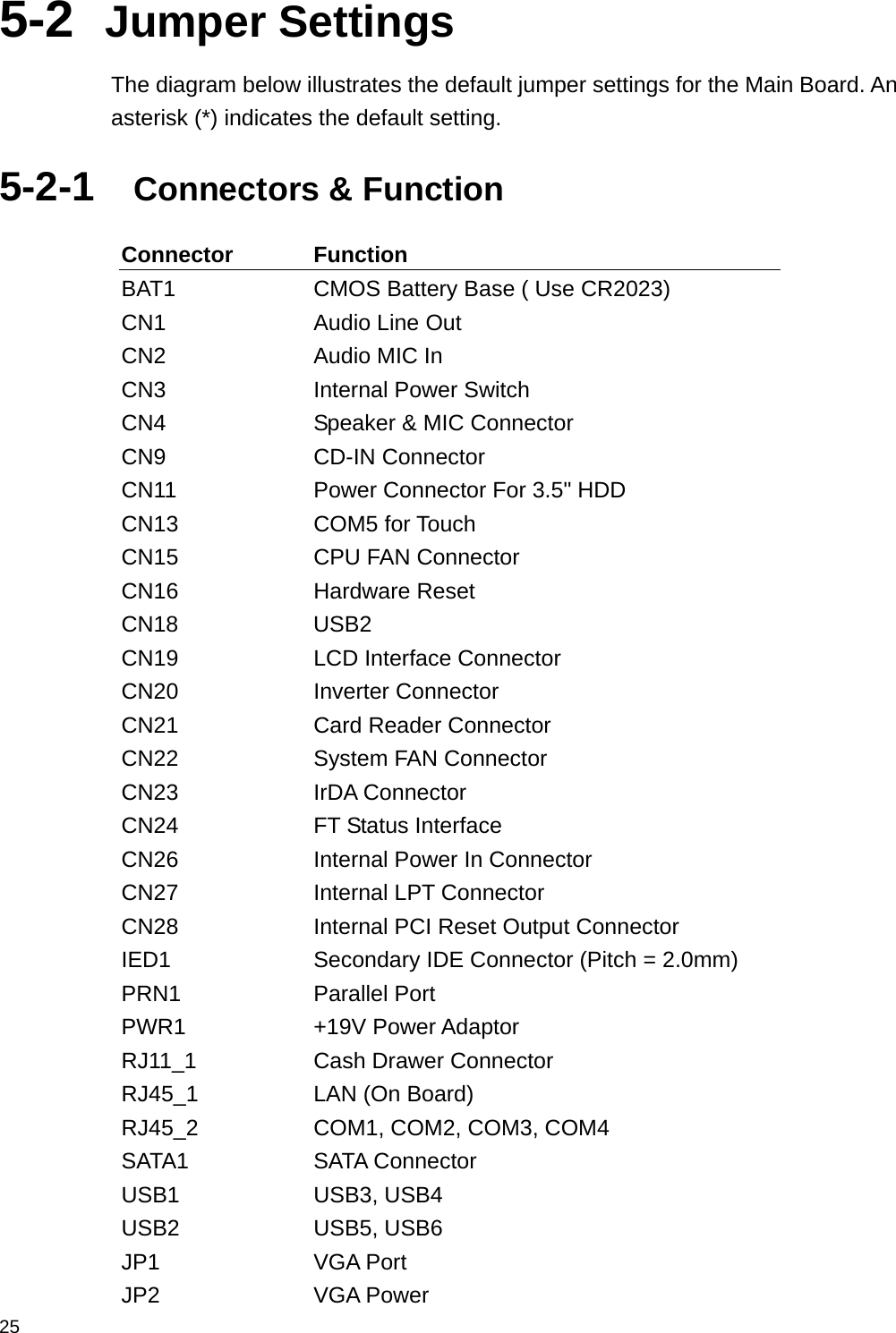
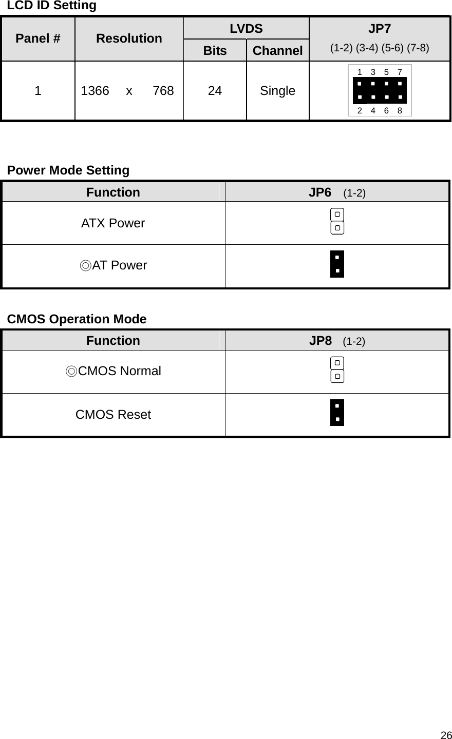
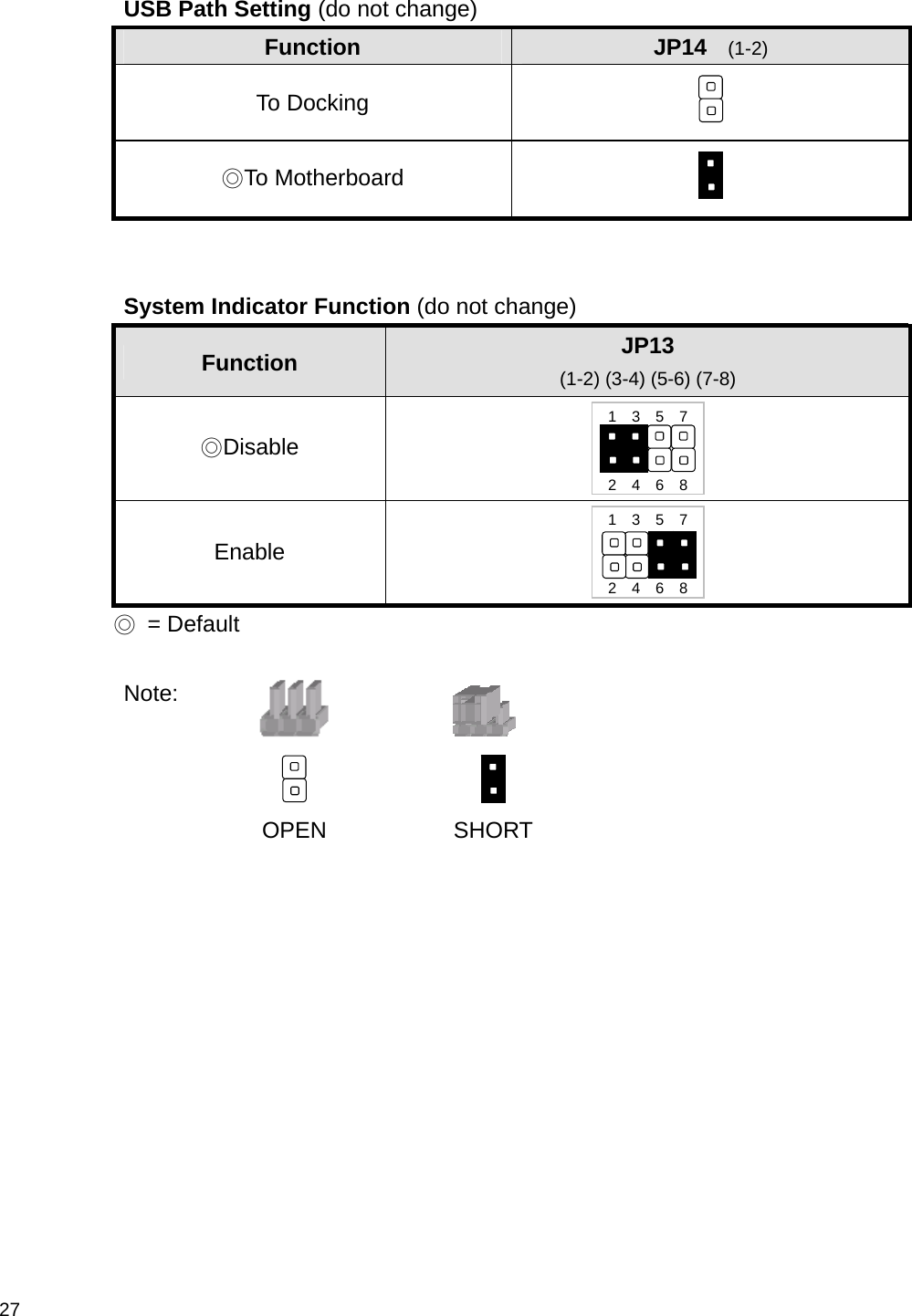
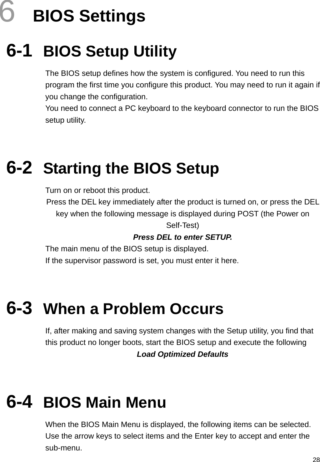
FLYTECH TECHNOLOGY LS185000 Bedside Terminal User Manual Usr manual
FLYTECH TECHNOLOGY CO., LTD Bedside Terminal Usr manual
UserManual.wiki
>
FLYTECH TECHNOLOGY
>
LS185000 User Manual
Usr manual
Navigation menu
Upload a User Manual
Namespaces
Wiki Guide
HTML
PDF
Info
Views
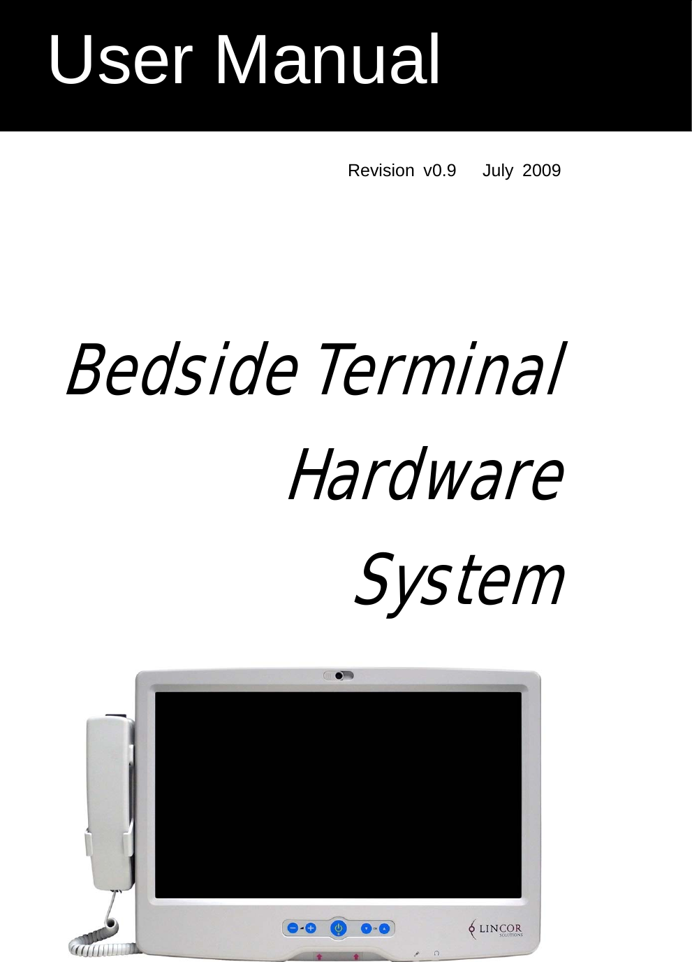
User Manual
Discussion / Help
Navigation