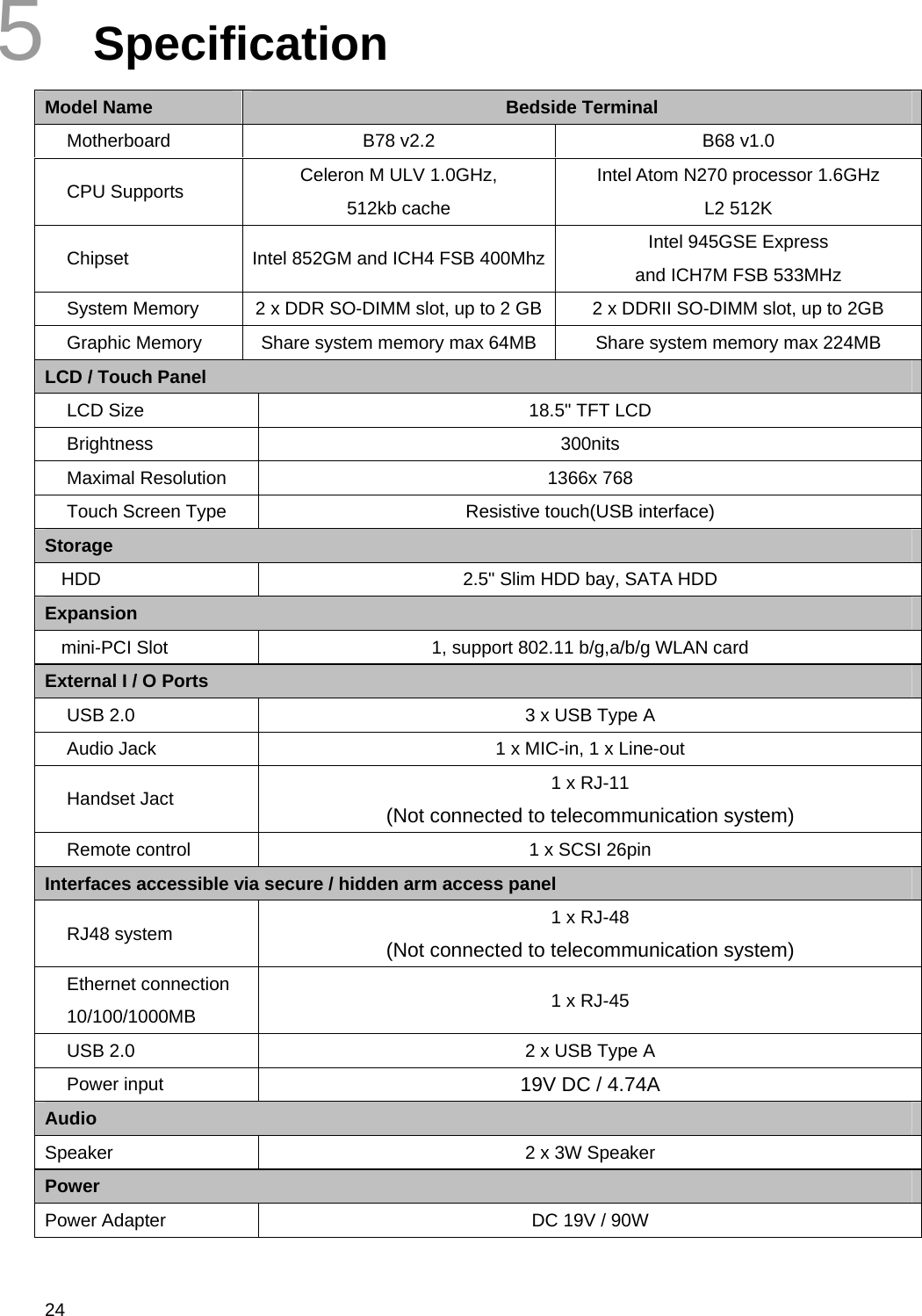
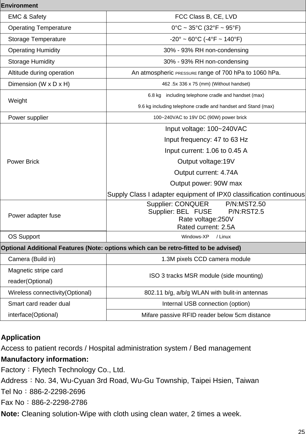
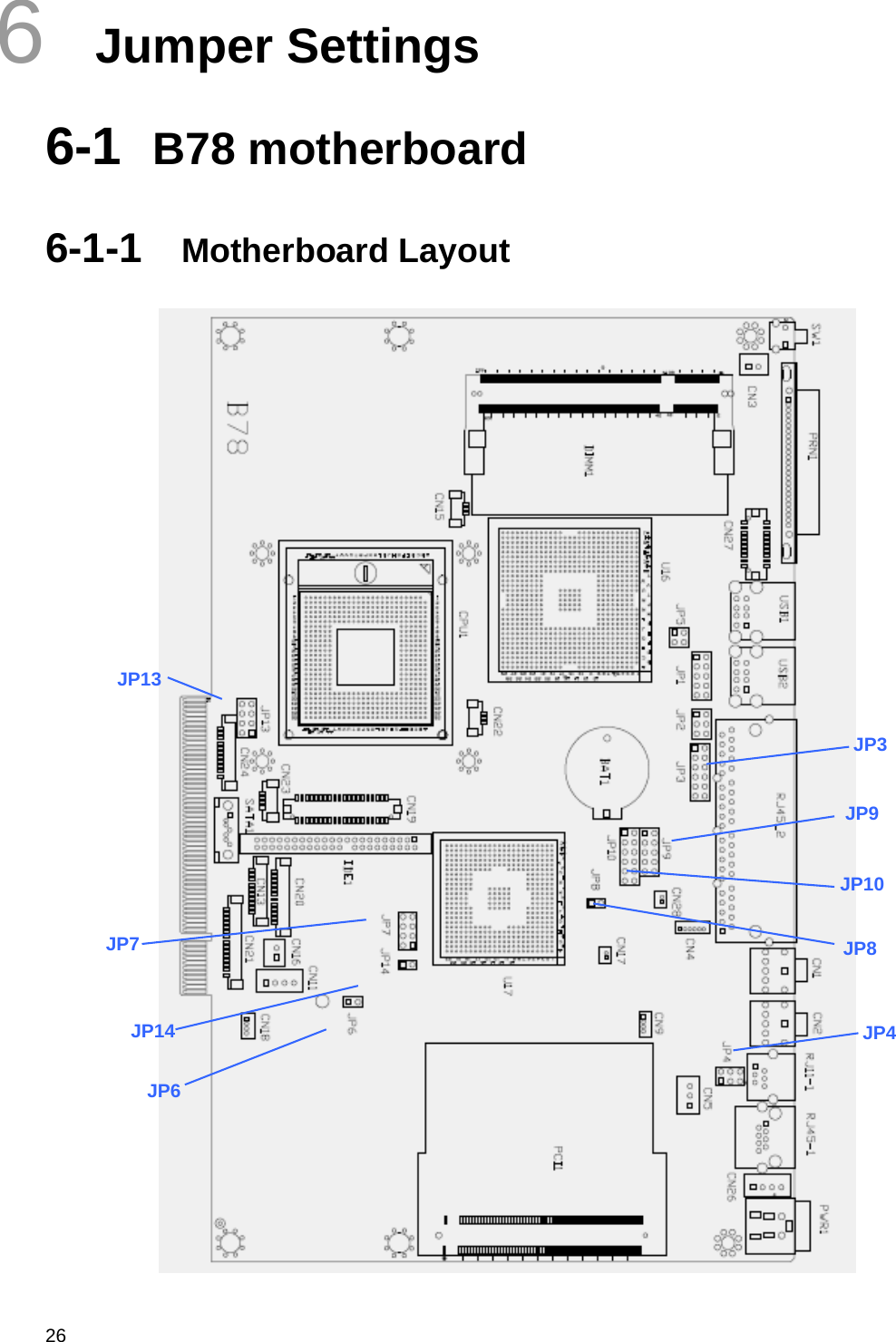
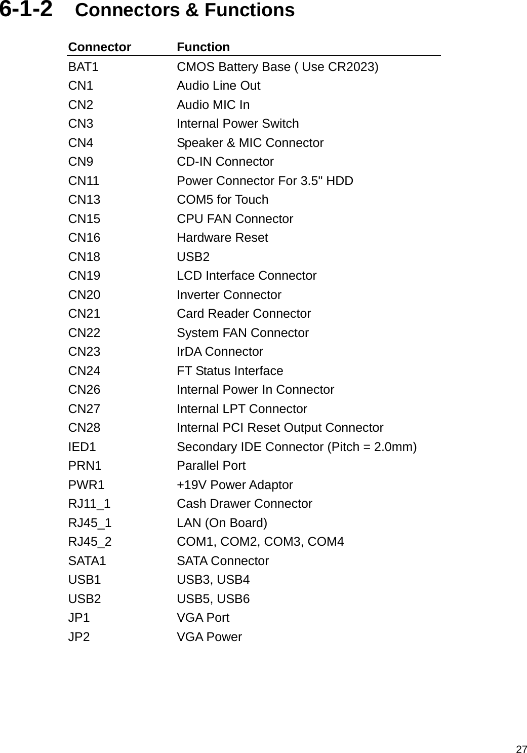
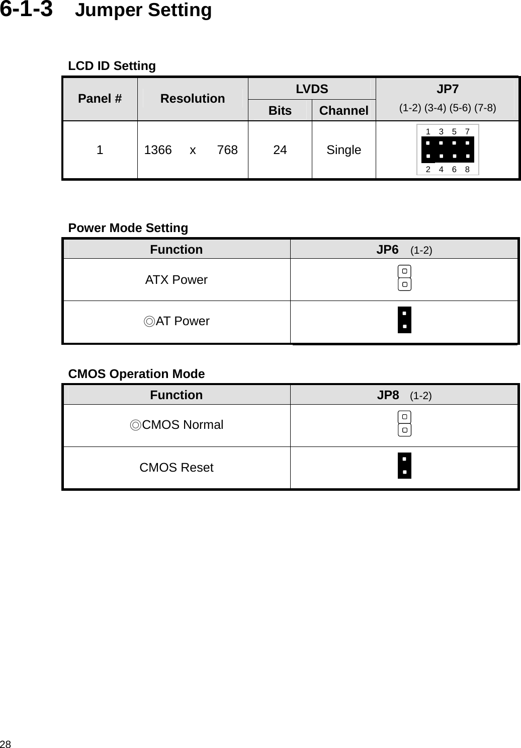
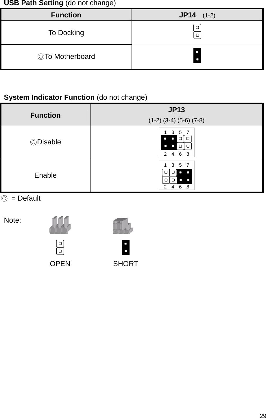
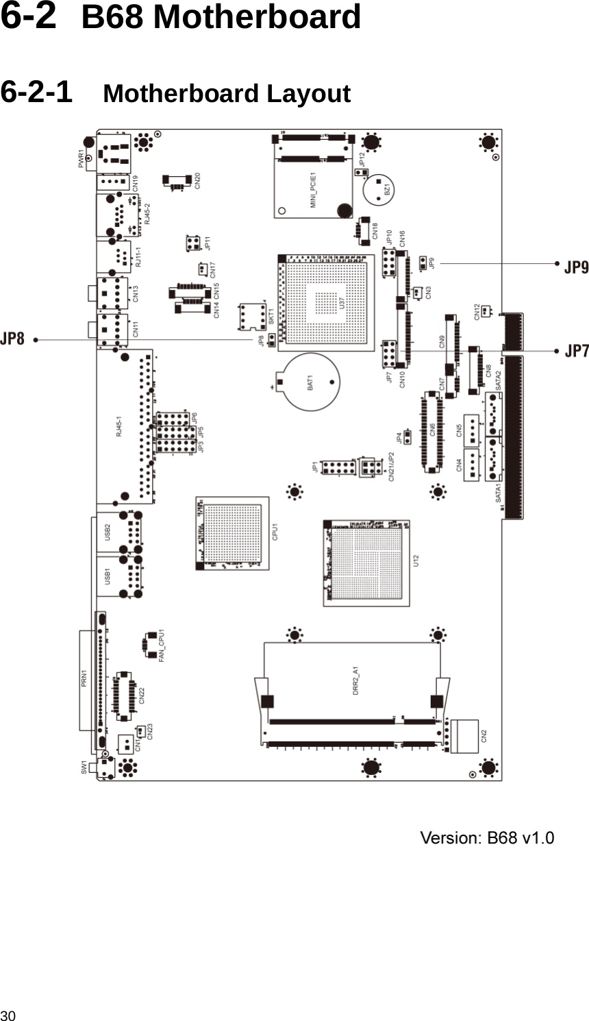
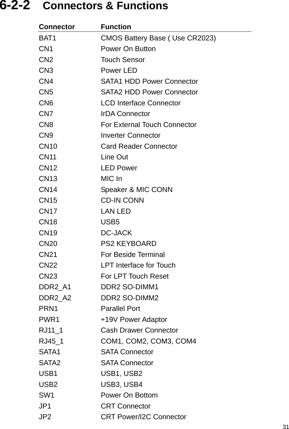
FLYTECH TECHNOLOGY LS185100 Bedside Terminal Hardware System User Manual K938 User s manualRevised0906

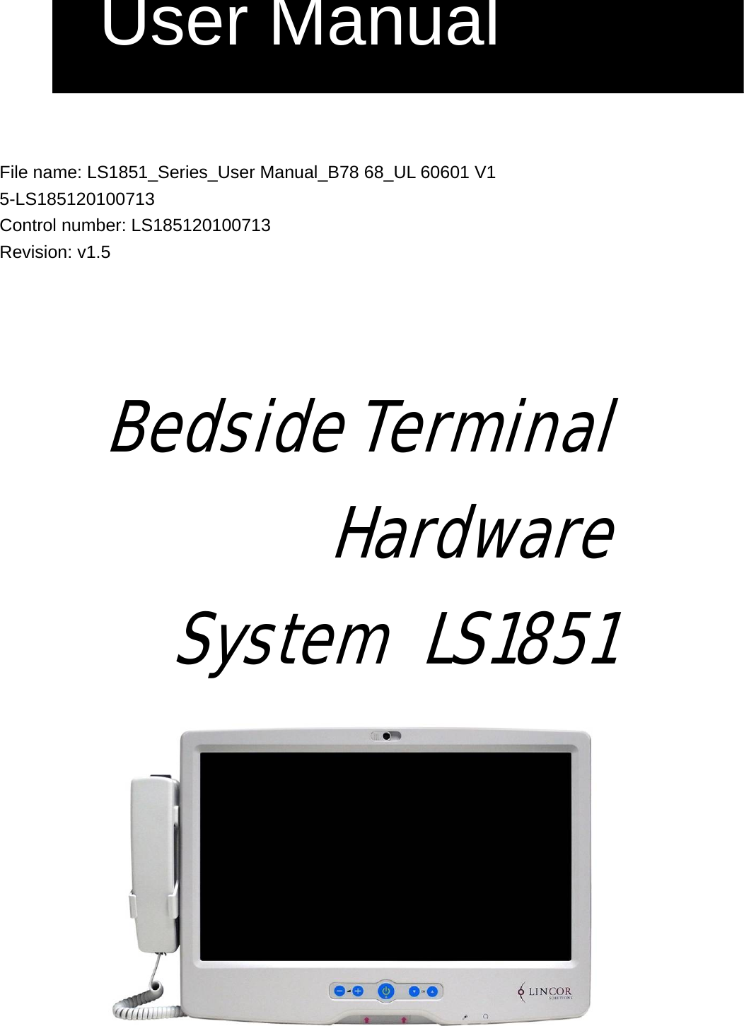
FLYTECH TECHNOLOGY CO., LTD Bedside Terminal Hardware System K938 User s manualRevised0906

User manual

   File name: LS1851_Series_User Manual_B78 68_UL 60601 V1 5-LS185120100713 Control number: LS185120100713 Revision: v1.5     Bedside Terminal Hardware  System LS1851  User Manual
 iCopyright 2010 July All Rights Reserved Manual Version 1.5 P/N:   The information contained in this document is subject to change without notice. We make no warranty of any kind with regard to this material, including, but not limited to, the implied warranties of merchantability and fitness for a particular purpose. We shall not be liable for errors contained herein or for incidental or consequential damages in connection with the furnishing, performance, or use of this material.  This document contains proprietary information that is protected by copyright. All rights are reserved. No part of this document may be photocopied, reproduced or translated to another language without the prior written consent of the manufacturer.     TRADEMARK Intel®, Pentium® and MMX are registered trademarks of Intel® Corporation. Microsoft® and Windows® are registered trademarks of Microsoft Corporation.   Other trademarks mentioned herein are the property of their respective owners.
 ii Safety  IMPORTANT SAFETY INSTRUCTIONS 1.  To disconnect the machine from the electrial power supply, turn off the power switch and remove the power cord plug from the wall socket. The wall socket must be easily accessible and in close proximity to the machine. 2.  Read these instructions carefully. Save these instructions for future reference. 3.  Follow all warnings and instructions marked on the product. 4.  Do not use this product near water. 5.  Do not place this product on an unstable cart,stand,or table.The product may fall, causing serious damage to the product. 6.  Slots and openings in the cabinet and the back or bottom are provided for ventilation;to ensure reliable operation of the product and to protect it from overheating. These openings must not be blocked or covered.The openings should never be blocked by placing the product on a bed, sofa, rug, or other similar surface.This product should never be placed near or over a radiator or heat register,or in a built-in installation unless proper ventilation is provided. 7.  This product should be operated from the type of power indicated on the marking label.If you are not sure of the type of power available, consult your dealer or local power company. 8.  Do not allow anything to rest on the power cord. Do not locate this product where persons will walk on the cord. 9.  Never push objects of any kind into this product through cabinet slots as they may touch dangerous voltage points or short out parts that could result in a fire or electric shock. Never spill liquid of any kind on the product.
 iii CE MARK   This device complies with the requirements of the EEC directive 2004/108/EC with regard to “Electromagnetic compatibility” and 2006/95/EC “Low Voltage Directive”.   FCC This device complies with part 15 of the FCC rules. Operation is subject to the following two conditions: (1) This device may not cause harmful interference.   (2) This device must accept any interference received, including interference that       may cause undesired operation.   Federal Communications Commission statement This equipment has been tested and found to comply with the limits for a class B digital device, pursuant to Part 15 of the FCC rules. These limits are designed to provide reasonable protection against harmful interference in a residential installation. This equipment generates, uses, and can radiate radio frequency energy and, if not installed and used in accordance with the instructions, may cause harmful interference to radio communications. However, there is no guarantee that interference will not occur in a particular installation. If this equipment does cause harmful interference to radio or television reception, which can be determined by turning the equipment off and on, the user is encouraged to try to correct the interference by one or more of the following measures: ˙Reorient or relocate the receiving antenna. ˙Increase the separation between the equipment and receiver.
 iv ˙Connect the equipment into an outlet on a circuit different from that to which the receiver is connected. ˙Consult the dealer or an experienced radio/TV technician for help. .interference that may cause undesired operation.   UL   CAUTION ON LITHIUM BATTERIES There is a danger of explosion if the battery is replaced incorrectly. Replace only with the same or equivalent type recommended by the manufacturer. Discard used batteries according to the manufacturer’s instructions.   LEGISLATION AND WEEE SYMBOL 2002/96/EC Waste Electrical and Electronic Equipment Directive on the treatment, collection, recycling and disposal of electric and electronic devices and their components.
 v  The crossed dustbin symbol on the device means that it should not be disposed of with other household wastes at the end of its working life. Instead, the device should be taken to the waste collection centers for activation of the treatment, collection, recycling and disposal procedure. To prevent possible harm to the environment or human health from uncontrolled waste disposal, please separate this from other types of wastes and recycle it responsibly to promote the sustainable reuse of material resources.   Household users should contact either the retailer where they purchased this product, or their local government office, for details of where and how they can take this item for environmentally safe recycling.   Business users should contact their supplier and check the terms and conditions of the purchase contract.  This product should not be mixed with other commercial wastes for disposal.    CAUTION SYMBOL IN CARTON
 vi          Attention Attention, consult ACCOMPANYING DOCUMENTS    You are cautioned that changes or modifications not expressly approved by the part responsible for compliance could void the user’s authority to operate the equipment.
 viiRevision History Changes to the original user manual are listed below:  Version  Date  Description 1.0 2009 July  Initial release 1.1  2009 Sep  Add Arm installation 1.2 2009 Sep  Add Arm application condition Modified connector wording 1.3 2010 May B68 motherboard added Jumper Setting updated 1.4  2010 July  Cleaning solution-Wipe with clean water. 1.5   2010 July 1. Add model number (page 1). 2. Add system weight including base, page 32). 3.Base installation (Page 31) 4. UL mark modified(Page 4 ) 5. Cleaning method (Page 33). 6. Caution symbol(Page 6) 7. Add File and control number(Page 1) 8. Remove nurse call wording(Page 32 ) 9. Remove mount description(Page 33) 10. Humidity range modified (Page 33) 11.Add attention mark (Page 6) 12.Add power adapter fuse spec(Page 33)
 viii Table Contents 1 Item Checklist......................................1 1-1 Standard Items ..........................................................1 2 System View........................................2 2-1 Front View .................................................................2 2-2 Rear View ..................................................................3 2-3 Side View...................................................................4 2-4 I/O View.....................................................................5 2-5 Stand .........................................................................6 3 Driver Installation.................................7 3-1 Driver List ..................................................................7 3-2 Chipset Driver Installation..........................................8 3-3 USB 2.0 Driver Installation.........................................9 3-4 VGA Driver Installation.............................................12 3-5 Audio Driver Installation...........................................13 3-6 10/100/1000MB LAN Driver Installation...................14 3-7 ELO Touch Driver Installation ..................................15 3-8 POSTouch Driver Installation...................................18 4 Peripheral Installation........................22 4-1 Phone Set Installation..............................................22 4-2 Stand Installation .....................................................23 5 Specification ......................................24 6 Jumper Settings ................................26 6-1 B78 motherboard.....................................................26 6-2 B68 Motherboard.....................................................30 7 BIOS Settings....................................35 7-1 BIOS Setup Utility....................................................35 7-2 Starting the BIOS Setup...........................................35 7-3 When a Problem Occurs..........................................35 7-4 BIOS Main Menu .....................................................35
 11  Item Checklist Take the system unit out of the carton. Remove the unit from the carton by holding it by the foam inserts. The following contents should be found in the carton:  1-1  Standard Items    Driver CD  Manual    Power Adapter   Power Cable    System Phone Module
 2 2  System View 2-1  Front View         System Overview table -1 Number  Component 1 Camera 2  TV Key pad (Power, volume and channel button) 3  Smart card reader slot 4  Phone set holder ① ② ③ ④
 3    2-2  Rear View              System Overview Table -2 Number  Component 1 Ventilation 2 VESA Holes 3  Rear I/O (USBx2, DC-IN, RJ48 , LAN Connector) 4  Phone Set Holder 5 RFID Sensor 6  Smart Card Reader Slot 7  MSR Slot (Option) 8 Speakers ① ② ③ ④ ⑤ ⑦ ⑥ ⑧ ⑧
 4   2-3  Side View   System Overview Table -3 Number  Component 1  Smart Card Reader Slot 2  MSR Slot (Option)   ① ②
 5  2-4  I/O View     System Overview Table -4 Number  Component Description 1  USB x 2 2 SCSI Connector 3  USB x 1 4  Phone Jack (RJ11) 5 Audio Line-out 6 Audio MIC-IN 7 Built-in MIC 8  Smart Card Reader Slot   ①  ② ③ ④ ⑤ ⑥ ⑧ ⑦
 6 2-5  Stand
 73  Driver Installation  3-1  Driver List   B78 V2.2 Driver List Folder/File  File Description <CD>:\ POS360_B78.htm  Driver List <CD>:\COMMON\INTEL\Chipset\i8xx Chipset Driver <CD>:\COMMON\INTEL\USB20  USB 2.0 Driver <CD>:\COMMON\INTEL\VGA\i85x VGA Driver <CD>:\COMMON\Ac97_codec\Realtek\ALC202A Audio Driver <CD>:\COMMON\ POS_Touch  POSTouch Driver <CD>:\COMMON\ELO_Touch ELO Touch Driver <CD>:\COMMON\Lan_driver\Realtek_PCI  10/100/1000Mb LAN Driver     -The following procedures are for Windows 2000/XP, other platforms are similar.
 8 3-2  Chipset Driver Installation      a. Click “Chipset” in the Driver List menu of POS360 B78.  b. Double-click “infinst_enu_6.0.1.1002.exe” on the My computer window.     c. Click the “Next” button on the Welcome window.  d. Click the “Yes” button on the License Agreement window.     e. Click the ”Next” button on the Readme Information window.  f. Click the “Finish” button and restart your system.
 93-3  USB 2.0 Driver Installation  OS Requirements OS  USB 2.0 requirements Windows XP  USB 2.0 drivers are provided in Service Pack 1 (SP1) for Windows XP, which is available through Windows Update.Windows 2000  USB 2.0 drivers are available through Windows Update or Service Pack 4. Windows 98SE/Me  USB 2.0 drivers are available on the Intel developer site. Windows 98 (Retail) Developers and OEMs should contact Orange Ware. For end-users, if your device does not ship with Windows 98 drivers, contact your device or system manufacturer. If USB 2.0 drivers are not available, your device will operate at USB 1.1 speeds Linux USB 2.0 support is available in kernel 2.4.19 or later development kernels, or in the 2.4.19 or later production kernel. More information.
 10    a. Right click My Computer on the desktop and select “properties”  b. Select  “Hardware””Device Manager” on system properties     c. Select ”Other Devices”  “Universal Serial Bus (USB) Controller” ”Properties” on Device Manager     d. Select  “Device” “Update Driver  e. Click the ”Next” button on the welcome window.
 11  f. Select “Search for a suitable…”and click the “Next” button on the Install Hardware Device Drivers window g. Select “Specify a location” and click the “Next” button on the Locate Driver Files window.     h. Press “Browse” to select the driver and then click the “OK” button to go to the next page i.  Click the “Next” button on the Driver Files Search Results window.     j.  Click the “Finish” button to complete this process.  k. Finished.
 12 3-4  VGA Driver Installation    a. Click “Win2K_XP” of “VGA” section in the Driver List menu.  b. Click “Run” when the “File Download – Security Warning” dialog pops up.      c. Click the “Next” button on the Intel(R) Chipset Graphics Driver Software- Install Shield(R) Wizard dialog. d. Click the “Next” button on the Intel(R) Graphics Media Accelerator Driver dialog.      e. Click the “Yes” button on the Intel(R) Graphics Media Accelerator Driver dialog. f. Select “Yes, I want to restart my computer now” and click the “Finish” button on the Intel(R) Graphics Media Accelerator Driver dialog.
 133-5  Audio Driver Installation    a. Click “Win9X,ME,2K_XP” of the “Audio” section in the Driver List menu. b. Double-click “A3.71” on the My Computer window.      c. Double-click “wdm_a371.exe” on the My Computer window.  d. Click “Next” button on the Realtek AC’97 Audio Setup window.     e. Click “Yes” button on the Digital Signature Not Found window.  f. Click “Finish” button on the Realtek AC’97 Audio Setup window.
 14 3-6  10/100/1000MB LAN Driver Installation   a. In the “Realtek RTL8110” section, click on Win9X, ME, 2K, XP  b. Double-click  “v709”     c. Double-click Setup.exe  d. Click the Finish button on the Maintenance Complete window.     e. Click the OK button and restart your system.
 153-7  ELO Touch Driver Installation   a. In the “ELO” section, click on “Windows”.  b. Click “Install Touch Driver” on “FT Touch Auto Install V1.0.2.0” window to detect the touch type in your system.     c. Click “Install Touch Driver”.  d. A “WinZip Self-Extractor” dialog will pop up. Click “OK”.     e. Click “Browse” button to identify a location or folder name to save to. Click “Unzip” button to extract the files. f. Finished unzipping. Click “OK”.
 16    g. Click “Next”.  h. Check the “Install Serial Touchscreen” Drivers” check box and click “Next”.     i.  Click “Yes” to accept the “End User License Agreement”.  j.  Examining serial ports on the computer     k. Check the box “Auto-detect Elo devices” and click “Next”.  l.  The computer is searching for a connected to Elo Touchscreen
 17  m.  Touchscreen found on “COM5”. Click “Next”.  n. Click “Next” to complete the driver installation     o. Driver is installing  p. The driver installation and setup are now complete. Click “Finish” to start the touchscreen calibration.      q. Follow the instructions on the screen to calibrate the Touchscreen.  r. Verify that the touchscreen is working correctly by moving your finger on the screen. The mouse cursor should follow your finger. Finally, touch the green checkmark to save the calibration settings and exit the program
 18 3-8  POSTouch Driver Installation    a. In the “Touch Screen auto…” section, click “Windows”.   b. Click “Install Touch Driver” on “FT Touch Auto Install V1.0.2.0” window to detect the touch type in your system.      c. “FT Touch Auto Install” program will detect what touch type and interface being installed on the system.  d. Click  ”Next”.      e. Select ”I agree…” and click ”Next”.   f. Select the installation folder for the touch utility driver and click ”Next”.
 19     g. Select the shortcut folder for the touch utility driver and click ”Next”.   h. Click  ”Next”.       i. Click ”Next”.   j.  The computer is installing the touch driver      k. Click ”Continue Anyway” button.   l. The serial ports are scanned for a touch device. The Touch panel is on COM5.
 20    m. Click ”Finish”.   n. Click ”OK” to restart the computer and finish the touch utility installation.      o. The computer has restarted. Click on the ”Start” button, select “Programs”, then select ”Touchutility”.  p. Select the Device tab.      q. Click on the 3 points or the 9 points calibration button.   r. Follow the instructions on the screen to do the calibration of the touch panel
 21  s. Touch anywhere on the screen to save the calibration.
 22 4  Peripheral Installation 4-1  Phone Set Installation    a.  Slide the Phone module into the Phone set holder as the direction of arrow shows. b.  Connect the phone cable to the connector on the Phone module.    c. Connect the other end of the Phone cable to the connector on the System.
 234-2  Stand Installation   a.  Four M6x10 screw for stand installation.
 24 5  Specification Model Name  Bedside Terminal Motherboard  B78 v2.2  B68 v1.0 CPU Supports  Celeron M ULV 1.0GHz, 512kb cache Intel Atom N270 processor 1.6GHz L2 512K Chipset  Intel 852GM and ICH4 FSB 400Mhz Intel 945GSE Express and ICH7M FSB 533MHz System Memory  2 x DDR SO-DIMM slot, up to 2 GB 2 x DDRII SO-DIMM slot, up to 2GB Graphic Memory  Share system memory max 64MB  Share system memory max 224MB LCD / Touch Panel LCD Size  18.5" TFT LCD Brightness 300nits Maximal Resolution  1366x 768 Touch Screen Type  Resistive touch(USB interface) Storage HDD 2.5" Slim HDD bay, SATA HDD Expansion mini-PCI Slot 1, support 802.11 b/g,a/b/g WLAN card External I / O Ports USB 2.0  3 x USB Type A Audio Jack  1 x MIC-in, 1 x Line-out Handset Jact    1 x RJ-11 (Not connected to telecommunication system) Remote control  1 x SCSI 26pin Interfaces accessible via secure / hidden arm access panel  RJ48 system  1 x RJ-48 (Not connected to telecommunication system) Ethernet connection 10/100/1000MB  1 x RJ-45 USB 2.0  2 x USB Type A Power input  19V DC / 4.74A Audio Speaker 2 x 3W Speaker Power Power Adapter DC 19V / 90W
 25 Environment EMC & Safety  FCC Class B, CE, LVD Operating Temperature  0°C ~ 35°C (32°F ~ 95°F) Storage Temperature  -20° ~ 60°C (-4°F ~ 140°F) Operating Humidity  30% - 93% RH non-condensing Storage Humidity  30% - 93% RH non-condensing Altitude during operation  An atmospheric PRESSURE range of 700 hPa to 1060 hPa. Dimension (W x D x H)  462 .5x 336 x 75 (mm) (Without handset) Weight  6.8 kg    including telephone cradle and handset (max) 9.6 kg including telephone cradle and handset and Stand (max) Power supplier  100~240VAC to 19V DC (90W) power brick Power Brick Input voltage: 100~240VAC Input frequency: 47 to 63 Hz Input current: 1.06 to 0.45 A Output voltage:19V Output current: 4.74A Output power: 90W max Supply Class I adapter equipment of IPX0 classification continuousPower adapter fuse Supplier: CONQUER         P/N:MST2.50 Supplier: BEL   FUSE         P/N:RST2.5 Rate voltage:250V Rated current: 2.5A OS Support  Windows-XP   / Linux Optional Additional Features (Note: options which can be retro-fitted to be advised) Camera (Build in)  1.3M pixels CCD camera module Magnetic stripe card reader(Optional)  ISO 3 tracks MSR module (side mounting) Wireless connectivity(Optional)  802.11 b/g, a/b/g WLAN with bulit-in antennas Internal USB connection (option) Smart card reader dual interface(Optional)  Mifare passive RFID reader below 5cm distance  Application Access to patient records / Hospital administration system / Bed management Manufactory information: Factory:Flytech Technology Co., Ltd. Address:No. 34, Wu-Cyuan 3rd Road, Wu-Gu Township, Taipei Hsien, Taiwan Tel No:886-2-2298-2696 Fax No:886-2-2298-2786 Note: Cleaning solution-Wipe with cloth using clean water, 2 times a week.
 26 6  Jumper Settings 6-1  B78 motherboard 6-1-1  Motherboard Layout  JP10JP9 JP3 JP4 JP7 JP6 JP8 JP14 JP13
 276-1-2  Connectors & Functions Connector Function BAT1  CMOS Battery Base ( Use CR2023) CN1 Audio Line Out CN2 Audio MIC In CN3  Internal Power Switch CN4  Speaker & MIC Connector CN9 CD-IN Connector CN11  Power Connector For 3.5" HDD CN13 COM5 for Touch CN15  CPU FAN Connector CN16 Hardware Reset CN18 USB2 CN19  LCD Interface Connector CN20 Inverter Connector CN21  Card Reader Connector CN22  System FAN Connector CN23 IrDA Connector CN24  FT Status Interface CN26  Internal Power In Connector CN27  Internal LPT Connector CN28  Internal PCI Reset Output Connector IED1  Secondary IDE Connector (Pitch = 2.0mm) PRN1 Parallel Port PWR1 +19V Power Adaptor RJ11_1  Cash Drawer Connector RJ45_1  LAN (On Board) RJ45_2  COM1, COM2, COM3, COM4 SATA1 SATA Connector USB1 USB3, USB4 USB2 USB5, USB6 JP1 VGA Port JP2 VGA Power
 28 6-1-3  Jumper Setting  LCD ID Setting LVDS Panel #  Resolution  Bits  ChannelJP7  (1-2) (3-4) (5-6) (7-8) 1 1366 x 768 24 Single    Power Mode Setting Function  JP6   (1-2) ATX Power   ◎AT Power    CMOS Operation Mode Function  JP8  (1-2) ◎CMOS Normal   CMOS Reset     1  3  5  7    2  4  6  8
 29  USB Path Setting (do not change) Function  JP14   (1-2) To Docking   ◎To Motherboard     System Indicator Function (do not change) Function  JP13 (1-2) (3-4) (5-6) (7-8) ◎Disable  Enable  ◎ = Default  Note:      OPEN SHORT  1  3  5  7     2  4  6  8   1  3  5  7     2  4  6  8
 30 6-2  B68 Motherboard 6-2-1  Motherboard Layout
 316-2-2  Connectors & Functions Connector Function BAT1  CMOS Battery Base ( Use CR2023) CN1  Power On Button CN2 Touch Sensor CN3 Power LED CN4  SATA1 HDD Power Connector CN5  SATA2 HDD Power Connector CN6  LCD Interface Connector CN7 IrDA Connector CN8  For External Touch Connector CN9 Inverter Connector CN10  Card Reader Connector CN11 Line Out CN12 LED Power CN13 MIC In CN14  Speaker & MIC CONN CN15 CD-IN CONN CN17 LAN LED CN18 USB5 CN19 DC-JACK CN20 PS2 KEYBOARD CN21 For Beside Terminal CN22  LPT Interface for Touch CN23  For LPT Touch Reset DDR2_A1 DDR2 SO-DIMM1 DDR2_A2 DDR2 SO-DIMM2 PRN1 Parallel Port PWR1 +19V Power Adaptor RJ11_1  Cash Drawer Connector RJ45_1  COM1, COM2, COM3, COM4 SATA1 SATA Connector SATA2 SATA Connector USB1 USB1, USB2 USB2 USB3, USB4 SW1  Power On Bottom JP1 CRT Connector JP2  CRT Power/I2C Connector
 32 JP7  LCD ID Setting JP8 RTC Reset JP9 AT Function JP12 Hardware Reset
 336-2-3  Jumper Setting   Power Mode Setting Function  JP9  (1-2) ATX Power   ◎AT Power     CMOS Operation Mode Function  JP8  (1-2) ◎CMOS Normal   CMOS Reset      LCD ID Setting LVDS Panel #  Resolution  Bits Channel Output Interface JP7  (1-2) (3-4)   (5-6) (7-8) ◎1  1366 x 768  24  Single  LVDS  Panel  2  1440 x 900  24  Dual  LVDS Panel  4  1920 x 1080  24  Dual  LVDS Panel
 34 LVDS Panel #  Resolution  Bits Channel Output Interface JP7  (1-2) (3-4)   (5-6) (7-8) 5  1024 x 768  24  Single  LVDS Panel  6  1280 x 1024  24  Dual  LVDS Panel  7  800 x 600  24  Single  LVDS Panel  9  1024 x 768  18  Single  LVDS Panel  11  800 x 600  18  Single  LVDS Panel  12  800 x 600  18  Single  LVDS Panel         CRT         Remark:   Panel ID#12 is specialized for Sharp 12.1” LQ121S1LG41/   LQ121S1LG42 panel.    Note:      OPEN SHORT
 357  BIOS Settings 7-1  BIOS Setup Utility The BIOS setup defines how the system is configured. You need to run this program the first time you configure this product. You may need to run it again if you change the configuration. You need to connect a PC keyboard to the keyboard connector to run the BIOS setup utility.   7-2  Starting the BIOS Setup Turn on or reboot this product. Press the DEL key immediately after the product is turned on, or press the DEL key when the following message is displayed during POST (the Power on Self-Test)  Press DEL to enter SETUP. The main menu of the BIOS setup is displayed. If the supervisor password is set, you must enter it here.   7-3  When a Problem Occurs If, after making and saving system changes with the Setup utility, you find that this product no longer boots, start the BIOS setup and execute the following Load Optimized Defaults   7-4  BIOS Main Menu When the BIOS Main Menu is displayed, the following items can be selected. Use the arrow keys to select items and the Enter key to accept and enter the sub-menu.
 36 Note: The BIOS setup menus shown in this section are for reference only and may not exactly match the items of your BIOS version. .  Standard CMOS Features Use this menu for basic system configuration.  Advanced BIOS Features Use this menu to set the Advanced Features available on the system.  Advanced Chipset Features Use this menu to change the values in the chipset registers and optimize the system’s performance.  Integrated Peripherals Use this menu to specify your settings for integrated peripherals.  Power Management setup Use this menu to specify your settings for power management.  PnP/PCI Configurations This entry appears if your system supports Plug and Play and PCI Configuration.  PC health status Displays CPU, System Temperature, Fan Speed, and System Voltages Value.  Load Optimized Defaults
 37Use this menu to load the BIOS default values, i.e., factory settings for optimal performance system operations. While Award has designed the custom BIOS to maximize performance, the factory has the option to change these defaults to meet their needs.  Set Supervisor Password   Enables you to change, set, or disable the supervisor or user password.  Set Password   Change, set, or disable the password. It allows you to limit access to the system and to the setup, or just to the setup.  Save & exit setup Save CMOS value changes to CMOS and exits setup.  Exit without saving Ignores all CMOS value changes and exits setup.

Navigation menu