FLYTECH TECHNOLOGY LS185300 MEDIVista 18.5 Bedside Terminal User Manual PA79 V1 1
FLYTECH TECHNOLOGY CO., LTD MEDIVista 18.5 Bedside Terminal PA79 V1 1
User manual
Version 1.1 April 2015
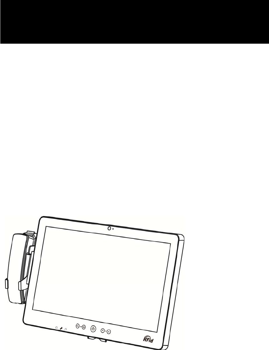
MEDIVista 18.5"
Bedside Terminal
User Manual
ii
Copyright 2015
All Rights Reserved
Manual Version 1.1
The information contained in this document is subject to change without notice.
We make no warranty of any kind with regard to this material, including, but not
limited to, the implied warranties of merchantability and fitness for a particular
purpose. We shall not be liable for errors contained herein or for incidental or
consequential damages in connection with the furnishing, performance, or use of
this material.
This document contains proprietary information that is protected by copyright. All
rights are reserved. No part of this document may be photocopied, reproduced or
translated to another language without the prior written consent of the
manufacturer.
TRADEMARK
Intel®, Pentium® and MMX are registered trademarks of Intel® Corporation.
Microsoft® and Windows® are registered trademarks of Microsoft Corporation.
Other trademarks mentioned herein are the property of their respective owners.

iii
Safety
IMPORTANT SAFETY INSTRUCTIONS
1. To disconnect the machine from the electrical Power Supply, turn off the power
switch and remove the power cord plug from the wall socket. The wall socket
must be easily accessible and in close proximity to the machine.
2. Read these instructions carefully. Save these instructions for future reference.
3. Follow all warnings and instructions marked on the product.
4. Do not place this product on an unstable cart, stand, or table. The product may
fall, causing serious damage to the product.
5. This product should be operated from the type of power indicated on the marking
label. If you are not sure of the type of power available, consult your dealer or
local power company.
6. Do not allow anything to rest on the power cord. Do not locate this product where
persons will walk on the cord.
CE MARK
This device complies with the requirements of the EEC directive 2004/108/EC
with regard to “Electromagnetic compatibility” and 2006/95/EC “Low Voltage
Directive”
FCC
This device complies with part 15 of the FCC rules. Operation is subject to the
following two conditions:
(1) This device may not cause harmful interference.
(2) This device must accept any interference received, including interference that
may cause undesired operation
This equipment has been tested and found to comply with the limits for a Class B
digital device, pursuant to part 15 of the FCC Rules. These limits are designed to
provide reasonable protection against harmful interference in a residential
installation. This equipment generates uses and can radiate radio frequency
energy and, if not installed and used in accordance with the instructions, may
cause harmful interference to radio communications. However, there is no
guarantee that interference will not occur in a particular installation. If this
equipment does cause harmful interference to radio or television reception,

iv
which can be determined by turning the equipment off and on, the user is
encouraged to try to correct the interference by one or more of the following
measures:
Reorient or relocate the receiving antenna.
Increase the separation between the equipment and receiver.
Connect the equipment into an outlet on a circuit different from that to which the
receiver is connected.
Consult the dealer or an experienced radio/TV technician for help.
Caution!
Any changes or modifications not expressly approved by the party responsible for
compliance could void the user's authority to operate the equipment.
CAUTION ON LITHIUM BATTERIES
There is a danger of explosion if the battery is replaced incorrectly. Replace only with
the same or equivalent type recommended by the manufacturer. Discard used
batteries according to the manufacturer’s instructions.
Battery Caution
Risk of explosion if battery is replaced by an incorrectly type.
Dispose of used battery according to the local disposal instructions.
Safety Caution
Note: To comply with IEC60950-1 Clause 2.5 (limited power sources, L.P.S) related
legislation, peripherals shall be 4.7.3.2 "Materials for fire enclosure" compliant.
4.7.3.2 Materials for fire enclosures
For MOVABLE EQUIPMENT having a total mass not exceeding
18kg.the material of a FIRE ENCLOSURE, in the thinnest significant
wall thickness used, shall be of V-1 CLASS MATERIAL or shall pass
the test of Clause A.2.
For MOVABLE EQUIPMENT having a total mass exceeding 18kg
and for all STATIONARY EQUIPMENT, the material of a FIRE
ENCLOSURE, in the thinnest significant wall thickness used, shall
be of 5VB CLASS MATERIAL or shall pass the test of Clause A.1

v
LEGISLATION AND WEEE SYMBOL
2012/19/EU Waste Electrical and Electronic Equipment Directive on the treatment,
collection, recycling and disposal of electric and electronic devices and their
components.
The crossed dustbin symbol on the device means that it should not be disposed of
with other household wastes at the end of its working life. Instead, the device
should be taken to the waste collection centers for activation of the treatment,
collection, recycling and disposal procedure.
To prevent possible harm to the environment or human health from uncontrolled
waste disposal, please separate this from other types of wastes and recycle it
responsibly to promote the sustainable reuse of material resources.
Household users should contact either the retailer where they purchased this
product, or their local government office, for details of where and how they can take
this item for environmentally safe recycling.
Business users should contact their supplier and check the terms and conditions of
the purchase contract.
This product should not be mixed with other commercial wastes for disposal.

vi
Revision History
Revision Date Description
V1.0 October, 2012 Release
V1.1 April, 2015 D35 M/B added
i
Table of Contents
1 Package Checklist .................................. 1
1-1 Standard Items .................................................................. 1
2 System View ............................................ 2
2-1 Front View ........................................................................... 2
2-2 Side View ............................................................................ 3
2-3 Rear View ........................................................................... 3
2-4 Bottom View ....................................................................... 4
2-5 Dimension .......................................................................... 4
3 System Assembly .................................... 5
3-1 SSD Card Replacement ..................................................... 5
4 Peripheral Installation ............................ 6
4-1 Phone module Installation ................................................ 6
5 Specification ........................................... 7
6 Jumper Settings ................................... 10
6-1 C43 Motherboard ............................................................ 10
6-2 D35 Motherboard ............................................................ 15
7 Drivers Installation .............................. 18
1
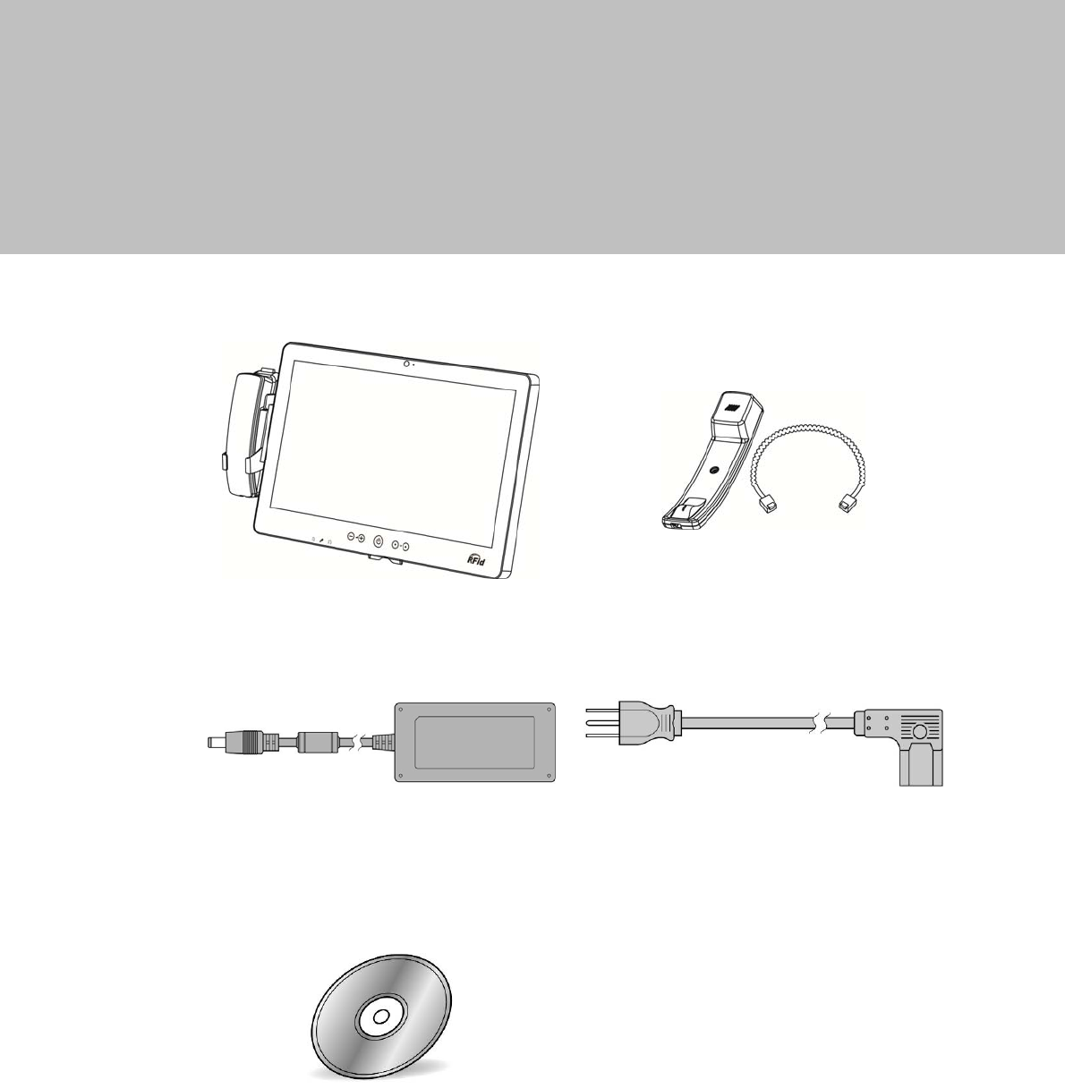
1 Package Checklist
1-1 Standard Items
a. System b. Phone module
c. Power adapter d. Power cable
e. Driver CD
2
2 System View
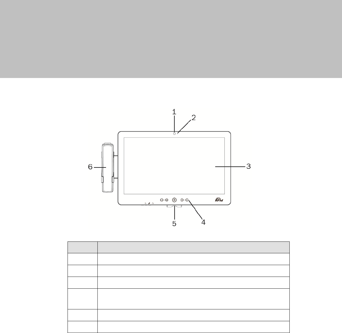
2-1 Front View
`
No. Description
1 Build-in camera
2 Camera LED
3 Touch screen
4 Touch keys (from left to right: volume down, volume up, power
button, channel down, channel up)
5 Smart IC card reader
6 VOIP phone (optional)
3
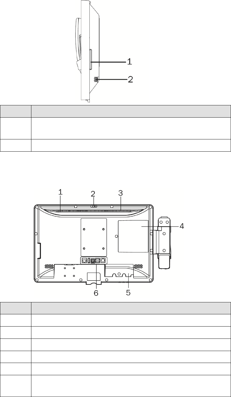
2-2 Side View
No. Description
1 Combo smart IC card reader with separate RFID antenna
(optional)
2 Speaker
2-3 Rear View
No. Description
1 Light Sensor
2 Webcam switch
3 Ventilation
4 SSD card door
5 Cable cover
6 Vertical I/O port (from left to right: Nurse call, Display port, DC
jack, USBx2, LAN )
4
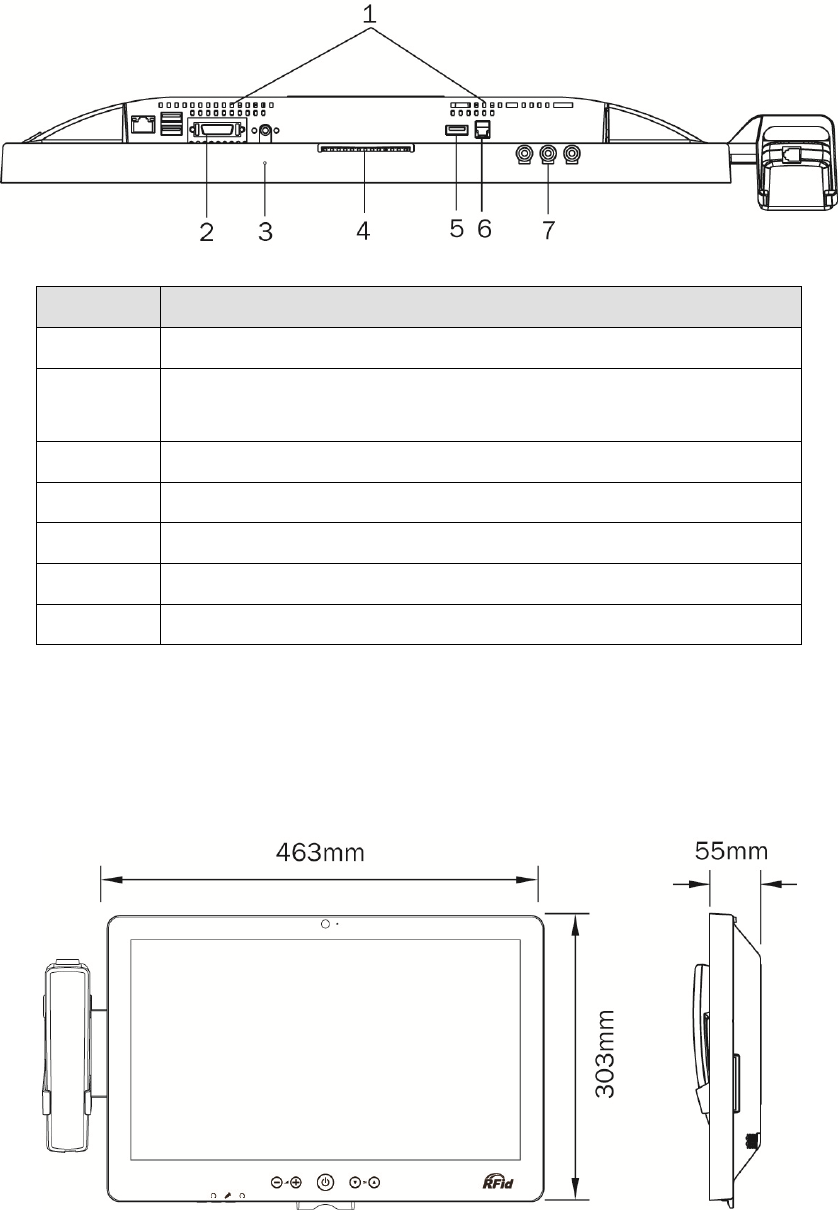
2-4 Bottom View
No. Description
1 Ventilation
2 Bottom I/O port (from let to right: LAN, USBx2, Remote,
Power button)
3 Microphone
4 Smart IC card reader
5 USBx1
6 Phone jack (RJ11)
7 From left to right: Audio line-out, Mic-in, Audio line-out
2-5 Dimension
5
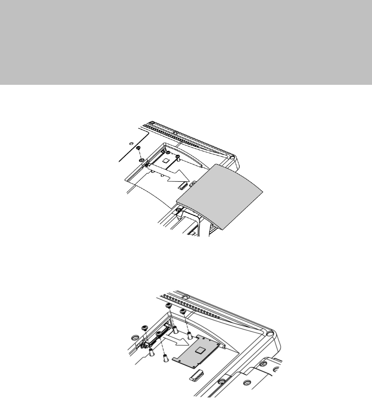
3 System Assembly
3-1 SSD Card Replacement
1. Find the SSD card door at the rear right side of the system and remove the
screws(x1)
2. To replace the SSD card, remove the screws (x4) and push the SSD card
outwards as shown in the picture.
6
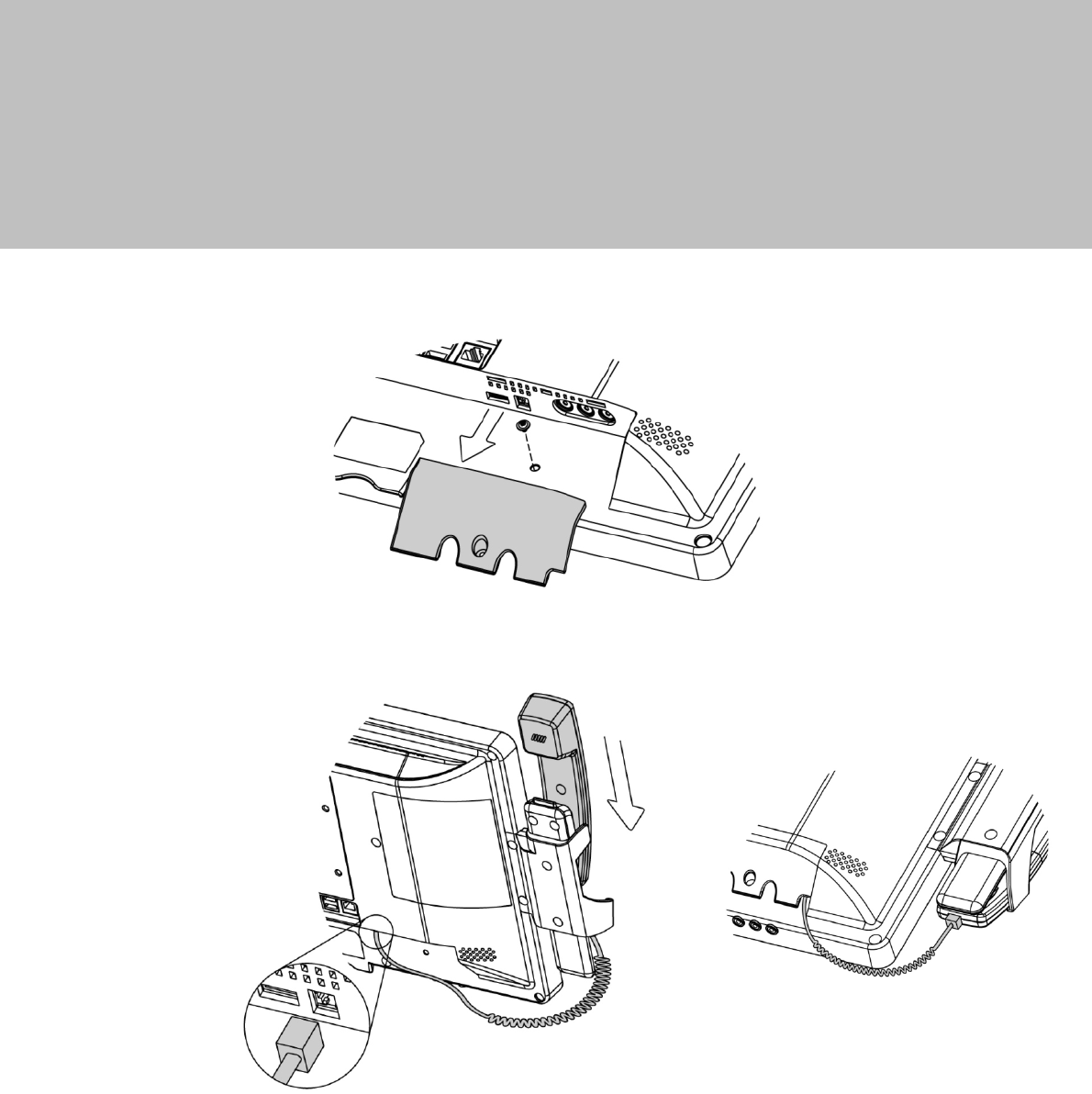
4 Peripheral Installation
4-1 Phone module Installation
1. Loosen the screw(x1) to open the cable cover.
2. Slide the phone module into the phone holder and connect the other end of
the phone cable to the connector on the system.
7
5 Specification
Model MEDIVista 18.5" Bedside Terminal
Motherboard C43 D35
Processor Pineview D525 Valleyview N2930, Quad-core 1.83G, 7.5W
Core Logic CPU with Graphic built-in + ICH 8M
Built-in SoC
System Memory 2 x DDR3 SO-DIMM slot up to 4GB
FSB800Mhz
1 x DDR3L SO-DIMM slot, FSB
1066/1333MHz default 2GB RAM (Max
8GB)
Graphic Memory Intel GMA 3150 share system
memory up to 256MB Intel Graphic DX11.1
LAN Controller / PHY Intel WG82583V / Intel WG82567V
Intel WG I211AT
Audio Controller Realtek ALC 662-GR HD codec
I/O Controller Winbond W83627UHG Winbond NCT6106D
Touch 18.5" TF P-cap
Camera LED Green-color (GPIO)
Microphone 1
Power LED Tri-color (GPIO)
Watch Dog Timer Hardware WDT
Display Size 18.5"
Resolution 1366x768
Brightness 250 nits
Power Supply 19V/65W
Storage
HDD 1 x SSD 16G w/ SATA interface
Expansion
Mini PCI e 2 x PCI-e full size slot 1 x Half size + 1 x Full size
Side I/O (Back-Left)
Smart IC Card Reader 1 (optional)
Rear I/O (Left)
LAN (2nd LAN) 1xRJ45 (with 10/100/1000,LED indicator)
USB 2 (USB 2.0)
Remote 1x SCSI 26pin
Reset Button 1, button can be pressed by probe
Power Button 1

8
Model MEDIVista 18.5" Bedside Terminal
Motherboard C43 D35
Rear I/O (Right)
USB 3.0 1
VOIP Phone 1 x RJ11
Rear I/O (Bottom)
USB 2.0 2
Line-out 2 (Auto-detect,GPIO), in external IO
Mic-In 1 (Auto-detect,GPIO), in external IO
Vertical I / O
LAN 1 x RJ45 (with 10/100/1000)
Power DC Jack
Display Port 1
USB 2 (USB 2.0)
Nurse Call 1 x RJ48
Touch Keys
Power Button 1xPower button (GPIO)
Channel Adjustment 1xChannel up, 1xChannel down (GPIO)
Volume 1xVolume up, 1xVolume down (GPIO)
LED Indicator
Power LED 1 (Tri-color) (GPIO)
Camera LED 1 (Green color) (GPIO)
Environment
EMC & Safety FCC Class B, CE, LVD / UL60950 /
EN60601
CE, FCC Class B, LVD / UL60950-1
(ESD Contact 6kV / Air 8kV)
Operating Temperature 0°C ~ 35°C (32°F ~ +95°F)
Storage Temperature -20°C ~ 60°C (-4°F ~ 140°F)
Humidity 20% - 85% RH non condensing
Weight
Weight 5Kgs
Operating System
OS Support Windows Embedded POSReady7,
Windows 7, Linux Windows 8, Linux
Communication & Peripherals
Speaker 2x3W
Build In Microphone In the bottom side
Webcam 5M web cam (USB interface) with webcam door (w/ fly LED cable to MB & control
by GPIO)

9
Model MEDIVista 18.5" Bedside Terminal
Motherboard C43 D35
VOIP Phone (Front left) Handset module (optional)
Smart IC Card Reader Comply with ISO 7816-1,2,3,T=1 and T=0 protocol
Combo Smart IC Card
Reader (optional) with
separate RFID antenna in
the front bezel
Comply with ISO 7816-1,2,3,T=1 and T=0
Support MIFARE, MIFARE+ ,Desfire, PC/SC 2.0, HID
Light Sensor Yes (GPIO)
10
6 Jumper Settings
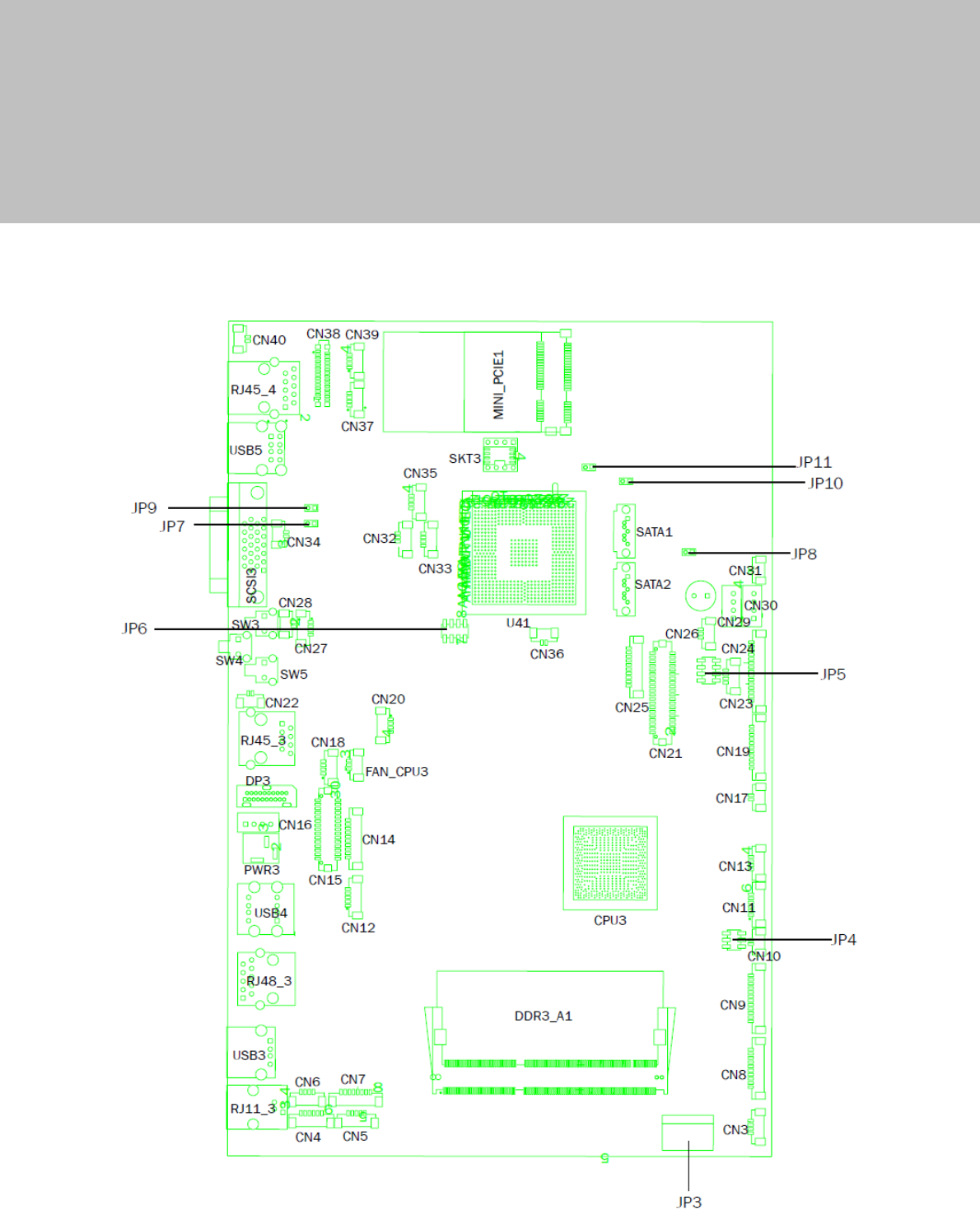
6-1 C43 Motherboard
6-1-1 Motherboard Layout

11
6-1-2 Connectors & Functions
Connector Function
CN3 USB Port For Web Cam
CN4 Speaker & MIC
CN5 Cradle
CN6 Speaker
CN7 Audio Jack (Line out & MIC)
CN9 Inverter
CN10 Build-In MIC
CN12 Nurse Call Button
CN14 Membrane
CN15 30P All-In-One
(Membrane, 2D scanner, RFID, Smart card, Audio Jack)
CN17 Nurse Call LED Power
CN18 Audio Jack (Line Out)
CN19/JP5 System Indicator
CN20 IrDA
CN21 LVDS
CN22 Power LED
CN23 PS/2 Keyboard
CN24 MSR
CN25 COM1
CN26 System FAN
CN27 MIC for AEC
CN28 Power Button
CN29/30 SATA Power
CN31 HDD LED
CN32/35 Internal USB
CN33 USB Port For DVD Dong
CN34 LAN2 LED
CN36 Battery
CN37 USB Port For RFID
CN38 2D Scanner
CN39 USB Port For Smart Card
CN40 LAN1 LED
DP3 DVI
PWR3 +19V DC Jack
RJ11_3 Handset

12
Connector Function
RJ45_3 LAN2
RJ45_4 LAN1
RJ48_3 Nurse Call
SATA1/2 SATA
SCSI_3 Remote Control
USB3 USB3
USB4 USB1, USB2 of HUB
USB5 USB1, USB2
JP3 Touch
JP4 Inverter Selection
JP6 LCD ID Setting
JP7 MCU Power Button
JP8 Power Mode Setting
JP9 MCU Mode Setting
JP10 System Reset
JP11 CMOS Operation Mode
13
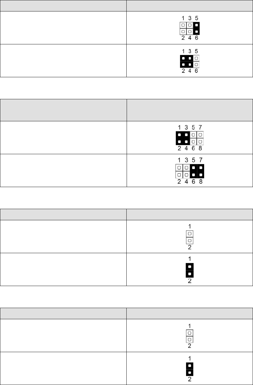
6-1-3 Jumper Settings
Inverter Selection
Function JP4 (1-2) (3-4) (5-6)
CCFL
▲LED
System Indicator
Function JP5
(1-2) (3-4) (5-6) (7-8)
▲Disable
Enable
MCU Power Button
Function JP7 (1-2)
Disable
▲Enable
Power Mode Setting
Function JP8 (1-2)
▲ATX Power
AT Power
14
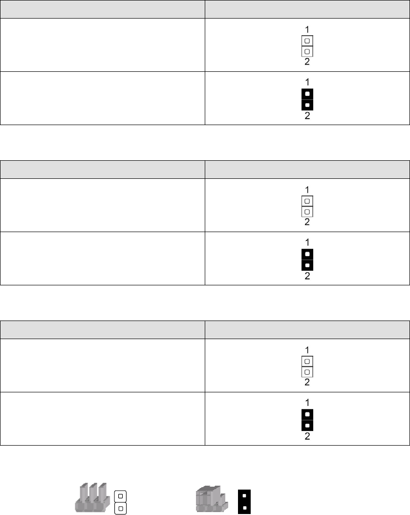
MCU Mode Setting
Function JP9 (1-2)
▲Normal
ISP Debug
System Reset
Function JP10 (1-2)
▲System Normal
System Reset
CMOS Operation Mode
Function JP11 (1-2)
▲CMOS Normal
CMOS Reset
▲ = Manufacturer Default Setting
Note:
OPEN SHORT
15
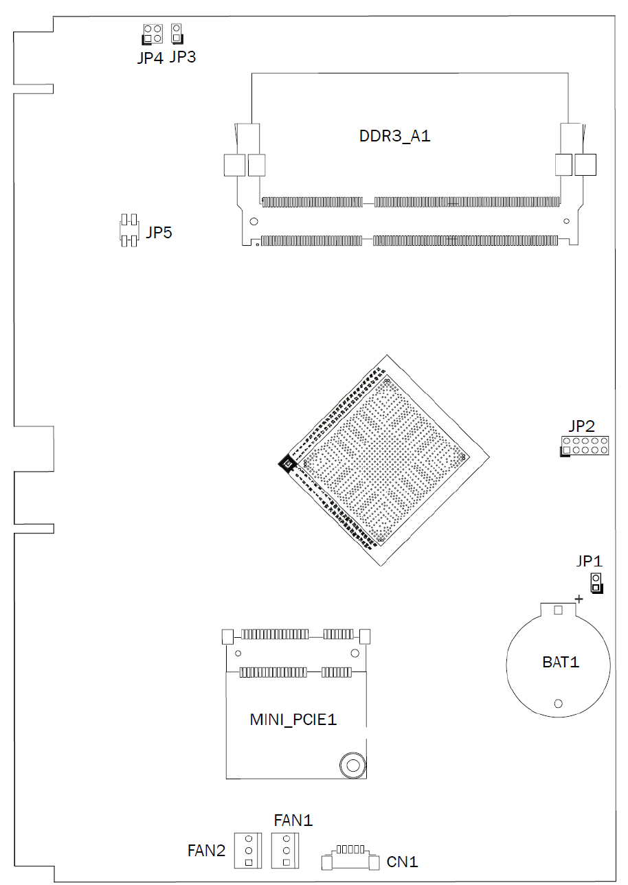
6-2 D35 Motherboard
6-2-1 Motherboard Layout

16
6-2-2 Connectors & Functions
Connector Function
CN12 SATA Power
CN6 Touch
CN27 Nurse Call LED
CN28 Push-Pull Button Connector
CN2 HDD LED
CN21 LVDS Connector
CN1 Power LED
CN4 Reading Light Connector
CN16 Speaker Connector
CN17 Audio Connector
CN8 Membrane Connector
CN5 COM Port
CN15 MSR Connector
CN29 USB 2.0
CN35 USB 2.0
CN18 AEC
FAN1 FAN
CN10 Light Sensor Connector
CN19 Build in MIC Connector
CN31 USB 2.0
CN32 USB 2.0
CN33 USB 2.0
CN9 Cradle Connector
CN20 Inverter Connector
CN34 Wide Range
RJ11_1 Handset
USB1 USB 3.0
RJ48_1 Nurse Call Connector
USB2 USB 2.0
PWR1 DC Jack
DP1 DVI/VGA Output
RJ45_2 LAN2
SW1 RESET Button
SW2 Power Button
SCSI1 Remote Control
USB4 USB 2.0
RJ45_1 LAN1
17
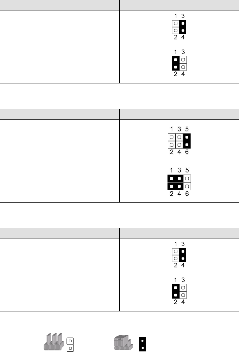
6-2-3 Jumper Settings
Inverter Selection
Function JP4 (1-2) (3-4)
CCFL
▲LED
F30 Inverter Selection
Function JP3 (1-2) (3-4) (5-6)
CCFL
▲LED
Cash Drawer Power Setting
Function JP5 (1-2) (3-4)
12V
▲19V
▲ = Manufacturer Default Setting
Note:
OPEN SHORT

18
7 Drivers Installation
The shipping package includes a Driver CD. You can find every individual driver and
utility that enables you to install the drivers in the Driver CD.
Please insert the Driver CD into the drive and double click on the “index.htm” to
pick up the models. You can refer to the drivers installation guide for each driver in
the “Driver/Manual List”.